


 Loading...
Service Manual
iR2030/2025/2022/2018 Series
Aug 8 2007
Application
This manual has been issued by Canon Inc. for qualified persons to learn technical theory, installation, maintenance, and repair of products. This manual covers all localities where the products are sold. For this reason, there may be information in this manual that does not apply to your locality.
Corrections
This manual may contain technical inaccuracies or typographical errors due to improvements or changes in products. When changes occur in applicable products or in the contents of this manual, Canon will release technical information as the need arises. In the event of major changes in the contents of this manual over a long or short period, Canon will issue a new edition of this manual.
The following paragraph does not apply to any countries where such provisions are inconsistent with local law.
Trademarks
The product names and company names used in this manual are the registered trademarks of the individual companies.
Copyright
This manual is copyrighted with all rights reserved. Under the copyright laws, this manual may not be copied, reproduced or translated into another language, in whole or in part, without the written consent of Canon Inc.
COPYRIGHT © 2001 CANON INC.
Printed in Japan
Caution
Use of this manual should be strictly supervised to avoid disclosure of confidential information.
Introduction
Symbols Used
This documentation uses the following symbols to indicate special information:
Symbol Description
Indicates an item of a non-specific nature, possibly classified as Note, Caution, or Warning.
Indicates an item requiring care to avoid electric shocks.
Indicates an item requiring care to avoid combustion (fire).
Indicates an item prohibiting disassembly to avoid electric shocks or problems.
Indicates an item requiring disconnection of the power plug from the electric outlet.
Indicates an item intended to provide notes assisting the understanding of the topic in question.
Memo
Indicates an item of reference assisting the understanding of the topic in question.
REF.
Provides a description of a service mode.
Provides a description of the nature of an error indication.

Introduction
The following rules apply throughout this Service Manual:
1.Each chapter contains sections explaining the purpose of specific functions and the relationship between electrical and mechanical systems with reference to the timing of operation.
In the diagrams,  represents the path of mechanical drive; where a signal name accompanies the symbol , the arrow
  indicates the
direction of the electric signal.
The expression "turn on the power" means flipping on the power switch, closing the front door, and closing the delivery unit door, which results in supplying the machine with power.
2.In the digital circuits, '1'is used to indicate that the voltage level of a given signal is "High", while '0' is used to indicate "Low".(The voltage value, however, differs from circuit to circuit.) In addition, the asterisk (*) as in "DRMD*" indicates that the DRMD signal goes on when '0'.
In practically all cases, the internal mechanisms of a microprocessor cannot be checked in the field. Therefore, the operations of the microprocessors used in the machines are not discussed: they are explained in terms of from sensors to the input of the DC controller PCB and from the output of the DC controller PCB to the loads.
The descriptions in this Service Manual are subject to change without notice for product improvement or other purposes, and major changes will be communicated in the form of Service Information bulletins.
All service persons are expected to have a good understanding of the contents of this Service Manual and all relevant Service Information bulletins and be able to identify and isolate faults in the machine."

Contents
Contents
Chapter 1 Introduction |
|
1.1 System Construction .................................................................................................................................. |
1- 1 |
1.1.1 Pickup/Delivery/Original Handling Accessories System Configuration (iR2018)..................................................... |
1- 1 |
1.1.2 Pickup/Delivery/Original Handling Accessories System Configuration (iR2018i).................................................... |
1- 2 |
1.1.3 Pickup/ Delivery /Original Handling Accessories System Configuration (iR2022/iR2022N/iR2025/iR2030)........... |
1- 3 |
1.1.4 Pickup/Delivery/Original Handling Accessories System Configuration (iR2022i/iR2022K/iR2025i/iR2030i)........... |
1- 4 |
1.1.5 Reader Heater/Cassette Heater System Configuration (iR2018/iR2022/iR2022N) ................................................ |
1- 5 |
1.1.6 Reader Heater/Cassette Heater System Configuration (iR2018i) ........................................................................... |
1- 6 |
1.1.7 Reader Heater/Cassette Heater System Configuration (iR2022K/iR2022i/iR2025/iR2025i/iR2030/iR2030i) ......... |
1- 7 |
1.1.8 Printing/Transmitting Accessories System Configuration (iR2018/ir2022/iR2022N) ............................................... |
1- 8 |
1.1.9 Printing/Transmitting Accessories System Configuration (iR2018i/iR2022i/iR2022K/iR2025/iR2025i/iR2030/iR2030i) |
|
1- 9 |
|
1.1.10 Functions of the Printing/Transmission Functions (iR2018/iR2022/iR2022N)..................................................... |
1- 10 |
1.1.11 Functions of the Printing/Transmission Functions (iR2018i/iR2022i/iR2022K/iR2025/iR2025i/IR2030/iR2030i) 1- 10 |
|
1.2 Product Specifications .............................................................................................................................. |
1- 10 |
1.2.1 Names of Parts...................................................................................................................................................... |
1- 10 |
1.2.1.1 External View (iR2030i/iR2025i/iR2022i) ............................................................................................................................... |
1- 10 |
1.2.1.2 External View (iR2020/iR2020N/iR2030/iR2025) .................................................................................................................. |
1- 11 |
1.2.1.3 External View (iR2018i) ......................................................................................................................................................... |
1- 11 |
1.2.1.4 External View (iR2018) .......................................................................................................................................................... |
1- 12 |
1.2.1.5 Cross-Section ........................................................................................................................................................................ |
1- 12 |
1.2.2 Using the Machine................................................................................................................................................. |
1- 13 |
1.2.2.1 Turning On the Power Switch (iR2018/iR2022/iR2022N) ...................................................................................................... |
1- 13 |
1.2.2.2 Turning On the Power Switch (iR2018i/iR2020i/iR2020K/iR2025/iR2025i/iR2030/iR2030i) ................................................. |
1- 14 |
1.2.2.3 When Turning Off the Main Power Switch (iR2018/iR2022/iR2022N)................................................................................... |
1- 15 |
1.2.2.4 When Turning Off the Main Power Switch (iR2018i/iR2022i/iR2022K/iR2025/iR2025i/iR2030/iR2030i) .............................. |
1- 16 |
1.2.2.5 Control Panel ......................................................................................................................................................................... |
1- 17 |
1.2.3 User Mode Items ................................................................................................................................................... |
1- 18 |
1.2.3.1 Common Settings (iR2030i/iR2030/iR2025i/iR2025/iR2022i/iR2018i) .................................................................................. |
1- 18 |
1.2.3.2 Timer Settings (iR2030i/iR2030/iR2025i/iR2025/iR2022i/iR2018i)........................................................................................ |
1- 19 |
1.2.3.3 Adjustment/Cleaning (iR2030i/iR2030/iR2025i/iR2025/iR2022i/iR2018i).............................................................................. |
1- 19 |
1.2.3.4 Report Settings (iR2030i/iR2030/iR2025i/iR2025/iR2022i/iR2018i) ...................................................................................... |
1- 19 |
1.2.3.5 System Settings (iR2030i/iR2030/iR2025i/iR2025/iR2022i/iR2018i) ..................................................................................... |
1- 20 |
1.2.3.6 Copy Settings (iR2030i/iR2030/iR2025i/iR2025/iR2022i/iR2018i)......................................................................................... |
1- 21 |
1.2.3.7 Communication Settings (iR2030i/iR2030/iR2025i/iR2025/iR2022i/iR2018i) ........................................................................ |
1- 21 |
1.2.3.8 Printer Settings (iR2030i/iR2030/iR2025i/iR2025/iR2022i/iR2018i) ...................................................................................... |
1- 22 |
1.2.3.9 Address Book Settings (iR2030i/iR2030/iR2025i/iR2025/iR2022i/iR2018i)........................................................................... |
1- 23 |
1.2.3.10 Recommended setting of system management information ................................................................................................ |
1- 23 |
1.2.3.11 The Reference Information of the Department ID Management .......................................................................................... |
1- 23 |
1.2.4 Maintenance by the User....................................................................................................................................... |
1- 23 |
1.2.4.1 User Maintenance Items ........................................................................................................................................................ |
1- 23 |
1.2.4.2 Cleaning (LCD type) .............................................................................................................................................................. |
1- 24 |
1.2.4.3 Cleaning (Touch panel type).................................................................................................................................................. |
1- 25 |
1.2.5 Safety .................................................................................................................................................................... |
1- 26 |
1.2.5.1 Safety of the Laser Light ........................................................................................................................................................ |
1- 26 |
1.2.5.2 CDRH Regulations................................................................................................................................................................. |
1- 26 |
1.2.5.3 Handling the Laser Unit ........................................................................................................................................................ |
1- 26 |
1.2.5.4 Handling the Laser Unit ......................................................................................................................................................... |
1- 27 |
1.2.5.5 Safety of Toner ...................................................................................................................................................................... |
1- 28 |
1.2.5.6 Point to Note about Fire ......................................................................................................................................................... |
1- 28 |
1.2.5.7 Cautions as to the replacement and disposal of lithium battery............................................................................................. |
1- 28 |
1.2.6 Product Specifications ........................................................................................................................................... |
1- 29 |
1.2.6.1 Product Specifications ........................................................................................................................................................... |
1- 29 |

Contents
1.2.7 Function List........................................................................................................................................................... |
1- 30 |
1.2.7.1 Printing Speed (iR2030/iR2030i) ........................................................................................................................................... |
1- 30 |
1.2.7.2 Printing Speed (iR2025/iR2025i) ........................................................................................................................................... |
1- 31 |
1.2.7.3 Printing Speed (iR2022/iR2022i/iR2022K/iR2022N)) ............................................................................................................ |
1- 32 |
1.2.7.4 Printing Speed (iR2018/iR2018i/iR2018N) ............................................................................................................................ |
1- 34 |
1.2.7.5 Types of Paper....................................................................................................................................................................... |
1- 35 |
Chapter 2 Installation |
|
2.1 Making Pre-Checks .................................................................................................................................... |
2- 1 |
2.1.1 Selecting the Site of Installation............................................................................................................................... |
2- 1 |
2.1.2 Before Starting the Work (230V CENV)................................................................................................................... |
2- 1 |
2.1.3 Before Starting the Work (230V CENV)................................................................................................................... |
2- 4 |
2.2 Unpacking and Installation ......................................................................................................................... |
2- 6 |
2.2.1 Unpacking and Removing the Packaging Materials ................................................................................................ |
2- 6 |
2.2.2 Unpacking and Removing the Packaging Materials ................................................................................................ |
2- 6 |
2.2.3 Installing the Drum Unit............................................................................................................................................ |
2- 6 |
2.2.4 Installing the Toner Bottle ........................................................................................................................................ |
2- 8 |
2.2.5 Installing the Toner Bottle ........................................................................................................................................ |
2- 9 |
2.2.6 Setting the Cassettes............................................................................................................................................. |
2- 10 |
2.2.7 Attaching the Ferrite Core...................................................................................................................................... |
2- 11 |
2.2.8 Checking the Image Quality................................................................................................................................... |
2- 11 |
2.2.9 Setting the Country/Region.................................................................................................................................... |
2- 11 |
2.2.10 Setting the Country/Region .................................................................................................................................. |
2- 11 |
2.2.11 Setting the Date and Time ................................................................................................................................... |
2- 12 |
2.2.12 Setting the Date and Time ................................................................................................................................... |
2- 13 |
2.2.13 Attaching Other Parts........................................................................................................................................... |
2- 14 |
2.3 Checking the Connection to the Network ................................................................................................. |
2- 15 |
2.3.1 Checking the Network Connection......................................................................................................................... |
2- 15 |
2.3.2 Checking the Network Connection......................................................................................................................... |
2- 16 |
2.4 Flow of Accessory Installation .................................................................................................................. |
2- 17 |
2.4.1 Flow of Accessary Installation (230V CENV)......................................................................................................... |
2- 17 |
2.4.2 Flow of Accessary Installation (230V CENV)......................................................................................................... |
2- 18 |
2.5 Installing the Card Reader........................................................................................................................ |
2- 19 |
2.5.1 Points to Note ........................................................................................................................................................ |
2- 19 |
2.5.2 Checking the Contents........................................................................................................................................... |
2- 19 |
2.5.3 Installation Procedure ............................................................................................................................................ |
2- 21 |
2.5.4 Registering the Card IDs........................................................................................................................................ |
2- 26 |
2.5.5 Registering the Card IDs........................................................................................................................................ |
2- 28 |
2.6 Installing the Heater PCB ......................................................................................................................... |
2- 29 |
2.6.1 Preparing the parts ................................................................................................................................................ |
2- 29 |
2.6.2 Preparing the Host Machine .................................................................................................................................. |
2- 29 |
2.6.3 Installing the Heater PCB....................................................................................................................................... |
2- 32 |
2.7 Installing the Reader Heater..................................................................................................................... |
2- 35 |
2.7.1 Preparing the parts ................................................................................................................................................ |
2- 35 |
2.7.2 Installing the Reader Heater Harness.................................................................................................................... |
2- 36 |
2.7.3 Removing Reader Components............................................................................................................................. |
2- 41 |
2.7.4 Removing Parts at the Left of the Reader.............................................................................................................. |
2- 41 |
2.7.5 Installing the Reader Heater .................................................................................................................................. |
2- 43 |
2.8 Installing the Cassette Heater .................................................................................................................. |
2- 47 |
2.8.1 Preparing the parts ................................................................................................................................................ |
2- 47 |
2.8.2 Installing the Cassette Heater................................................................................................................................ |
2- 48 |
2.9 Installing the Control Card Cable ............................................................................................................. |
2- 51 |
2.9.1 |
Preparing the parts ................................................................................................................................................ |
2- 51 |
2.9.2 |
Installing the Control Card Cable ........................................................................................................................... |
2- 52 |
|
Contents |
|
|
|
|
Chapter 3 Main Controller |
|
3.1 Construction ............................................................................................................................................... |
3- 1 |
3.1.1 Construction and Mechanisms ................................................................................................................................ |
3- 1 |
3.2 Construction of the Electrical Circuitry........................................................................................................ |
3- 1 |
3.2.1 Image Processor PCB ............................................................................................................................................. |
3- 1 |
3.3 Image Processing....................................................................................................................................... |
3- 2 |
3.3.1 Overview of the Image Flow .................................................................................................................................... |
3- 2 |
3.3.2 Construction of the Image Processing Module........................................................................................................ |
3- 3 |
3.3.3 Reader Unit Input Image Processing....................................................................................................................... |
3- 3 |
3.3.4 Compressio/ Extesion/ Editing Block...................................................................................................................... |
3- 4 |
3.3.5 Printer unit Output Image Processing...................................................................................................................... |
3- 4 |
3.4 Flow of Image Data .................................................................................................................................... |
3- 5 |
3.4.1 Flow of Image Data According to Copy Functions .................................................................................................. |
3- 5 |
3.4.2 Flow of Image Data for the SEND Function ............................................................................................................ |
3- 5 |
3.4.3 Flow of Image Data for the Fax Transmission......................................................................................................... |
3- 6 |
3.4.4 Flow of Image Data for the Fax Reception Function ............................................................................................... |
3- 6 |
3.4.5 Flow of Image Data for the PDL Function ............................................................................................................... |
3- 7 |
3.5 Parts Replacement Procedure ................................................................................................................... |
3- 8 |
3.5.1 Main Controller PCB................................................................................................................................................ |
3- 8 |
3.5.1.1 Preparation for Removing the Image Processor PCB ............................................................................................................. |
3- 8 |
3.5.1.2 Removing the Image Processor PCB ...................................................................................................................................... |
3- 8 |
3.5.1.3 Procedure after Replacing the Image Processor PCB........................................................................................................... |
3- 10 |
3.5.2 SDRAM.................................................................................................................................................................. |
3- 10 |
3.5.2.1 Preparation for Removing the SDRAM .................................................................................................................................. |
3- 10 |
3.5.2.2 Removing the SDRAM........................................................................................................................................................... |
3- 11 |
Chapter 4 Original Exposure System |
|
4.1 Construction ............................................................................................................................................... |
4- 1 |
4.1.1 Specifications, Control Methods, and Functions (iR2030i/iR2030/iR2025i/iR2025/iR2022i/iR2022) ...................... |
4- 1 |
4.1.2 Specifications, Control Methods, and Functions (iR2018i/iR2018) ......................................................................... |
4- 1 |
4.1.3 Major Components (iR2030i/iR2030/iR2025i/iR2025/iR2022i/iR2022) ................................................................... |
4- 2 |
4.1.4 Major Components (iR2018i/iR2018) ...................................................................................................................... |
4- 3 |
4.1.5 Control System Configuration (iR2030i/iR2030/iR2025i/iR2025/iR2022i/iR2022) .................................................. |
4- 3 |
4.1.6 Control System Configuration (iR2018i/iR2018)...................................................................................................... |
4- 4 |
4.1.7 Reader Controller PCB (iR2030i/iR2030/iR2025i/iR2025/iR2022i/iR2022)............................................................. |
4- 5 |
4.1.8 Reader Controller PCB (iR2018i/iR2018)................................................................................................................ |
4- 5 |
4.2 Basic Sequence.......................................................................................................................................... |
4- 6 |
4.2.1 Basic Sequence at Power-on .................................................................................................................................. |
4- 6 |
4.2.2 Basic Sequence after Depression of Start Key (Book mode, One Sheet of original) .............................................. |
4- 7 |
4.2.3 Basic Sequence after Depression of Start Key (ADF Mode, One Sheet of Original) .............................................. |
4- 7 |
4.3 Various Control........................................................................................................................................... |
4- 8 |
4.3.1 Controlling the Scanner Drive System..................................................................................................................... |
4- 8 |
4.3.1.1 Outline...................................................................................................................................................................................... |
4- 8 |
4.3.1.2 Reader Motor Control .............................................................................................................................................................. |
4- 9 |
4.3.2 Contact Image Sensor (CIS) ................................................................................................................................... |
4- 9 |
4.3.2.1 Outline...................................................................................................................................................................................... |
4- 9 |
4.3.2.2 Analog Control Performed by the CIS (iR2022i/iR2022/iR2018i/iR2018) .............................................................................. |
4- 10 |
4.3.2.3 Analog Control Performed by the CIS (iR2030i/iR2030/iR2025i/iR2025/iR2022i/iR2022) .................................................... |
4- 11 |
4.3.3 Enlargement/Reduction ......................................................................................................................................... |
4- 11 |
4.3.3.1 Magnification Change in Vertical Scan Direction ................................................................................................................... |
4- 11 |
4.3.3.2 Magnification Change in Horizontal Scan Direction............................................................................................................... |
4- 11 |
4.3.4 Detecting the Size of Originals .............................................................................................................................. |
4- 11 |
4.3.4.1 Outline.................................................................................................................................................................................... |
4- 11 |
4.3.4.2 Outline of Original Size Detection .......................................................................................................................................... |
4- 12 |
4.3.5 Dirt Sensor Control ................................................................................................................................................ |
4- 13 |

Contents
4.3.5.1 Outline.................................................................................................................................................................................... |
4- 13 |
4.3.6 Image Processing .................................................................................................................................................. |
4- 15 |
4.3.6.1 Outline.................................................................................................................................................................................... |
4- 15 |
4.3.6.2 CMOS Sensor Drive .............................................................................................................................................................. |
4- 16 |
4.3.6.3 CMOS Sensor Output Gain Correction and Offset Correction............................................................................................... |
4- 16 |
4.3.6.4 CMOS Sensor Output A/D Conversion.................................................................................................................................. |
4- 16 |
4.3.6.5 Shading Correction (Outline) ................................................................................................................................................ |
4- 16 |
4.3.6.6 Shading Adjustment............................................................................................................................................................... |
4- 17 |
4.3.6.7 Shading Correction ................................................................................................................................................................ |
4- 17 |
4.4 Parts Replacement Procedure ................................................................................................................. |
4- 18 |
4.4.1 Copyboard glass .................................................................................................................................................... |
4- 18 |
4.4.1.1 Removing the Copyboard glass............................................................................................................................................. |
4- 18 |
4.4.1.2 Procedure after Replacing the Copyboard Glass (Model equipped with ADF)...................................................................... |
4- 18 |
4.4.1.3 Removing the ADF Reading Glass ........................................................................................................................................ |
4- 18 |
4.4.2 Reader Controller PCB .......................................................................................................................................... |
4- 18 |
4.4.2.1 Removing the Reader Controller PCB ................................................................................................................................... |
4- 18 |
4.4.3 Scanner Motor ....................................................................................................................................................... |
4- 20 |
4.4.3.1 Removing the Scanner Motor ................................................................................................................................................ |
4- 20 |
4.4.4 Contact sensor....................................................................................................................................................... |
4- 20 |
4.4.4.1 Removing the Contact Image Sensor (CIS)........................................................................................................................... |
4- 20 |
4.4.4.2 Procedure after Replacing the CIS(Touch panel type) .......................................................................................................... |
4- 20 |
4.4.5 Copyboard Cover Open/Close Sensor .................................................................................................................. |
4- 20 |
4.4.5.1 Removing the Copyboard Cover Open/Close Sensor (Front/Rear)....................................................................................... |
4- 20 |
4.4.6 Contact Sensor HP Sensor.................................................................................................................................... |
4- 21 |
4.4.6.1 Removing the Contact Sensor HP Sensor............................................................................................................................. |
4- 21 |
4.4.7 Original Size Sensor .............................................................................................................................................. |
4- 21 |
4.4.7.1 Removing the Original Sensor (Vertical Scan Direction) ....................................................................................................... |
4- 21 |
4.4.7.2 Removing the Original Sensor (Horizontal Scan Direction) ................................................................................................... |
4- 22 |
4.4.8 Reader Heater (option) .......................................................................................................................................... |
4- 22 |
4.4.8.1 Removing the Reader Heater (Right) .................................................................................................................................... |
4- 22 |
4.4.8.2 Removing the Reader Heater (Left)....................................................................................................................................... |
4- 22 |
Chapter 5 Laser Exposure |
|
5.1 Construction ............................................................................................................................................... |
5- 1 |
5.1.1 Overview .................................................................................................................................................................. |
5- 1 |
5.1.2 Specifications and Control Mechanism.................................................................................................................... |
5- 1 |
5.1.3 Main Components.................................................................................................................................................... |
5- 1 |
5.1.4 Control System Configuration .................................................................................................................................. |
5- 2 |
5.2 Various Controls......................................................................................................................................... |
5- 2 |
5.2.1 Controlling the Laser Activation Timing ................................................................................................................... |
5- 2 |
5.2.1.1 Laser Emission ON/OFF Control ............................................................................................................................................. |
5- 2 |
5.2.1.2 Horizontal Synchronization Control.......................................................................................................................................... |
5- 3 |
5.2.2 Controlling the Intensity of Laser Light..................................................................................................................... |
5- 3 |
5.2.2.1 Automatic Photocurrent Control (APC) .................................................................................................................................... |
5- 3 |
5.2.3 Controlling the Laser Scanner Motor ....................................................................................................................... |
5- 3 |
5.2.3.1 Laser Scanner Motor Control................................................................................................................................................... |
5- 3 |
5.2.4 Controlling the Laser Shutter ................................................................................................................................... |
5- 4 |
5.2.4.1 Laser Shutter Control............................................................................................................................................................... |
5- 4 |
5.3 Parts Replacement Procedure ................................................................................................................... |
5- 6 |
5.3.1 Laser Scanner Unit .................................................................................................................................................. |
5- 6 |
5.3.1.1 Removing the Laser Scanner Unit ........................................................................................................................................... |
5- 6 |
Chapter 6 Image Formation |
|
6.1 Construction ............................................................................................................................................... |
6- 1 |
6.1.1 |
Specifications of Image Formation System.............................................................................................................. |
6- 1 |
6.1.2 |
Major Components of Image Formation System ..................................................................................................... |
6- 1 |
|
Contents |
|
|
|
|
6.2 Image Formation Process .......................................................................................................................... |
6- 3 |
6.2.1 Image Formation Process ....................................................................................................................................... |
6- 3 |
6.3 Basic Sequence.......................................................................................................................................... |
6- 3 |
6.3.1 Basic Sequence of Operation.................................................................................................................................. |
6- 3 |
6.4 Driving and Controlling the High-Voltage System....................................................................................... |
6- 5 |
6.4.1 Outline ..................................................................................................................................................................... |
6- 5 |
6.5 Drum Unit ................................................................................................................................................... |
6- 5 |
6.5.1 Outline of the Drum Unit .......................................................................................................................................... |
6- 5 |
6.5.1.1 Outline...................................................................................................................................................................................... |
6- 5 |
6.5.2 Charging Mechanism............................................................................................................................................... |
6- 6 |
6.5.2.1 Primary Charging Bias Control ................................................................................................................................................ |
6- 6 |
6.6 Developing Unit .......................................................................................................................................... |
6- 6 |
6.6.1 Outline ..................................................................................................................................................................... |
6- 6 |
6.6.2 Developing Bias Control .......................................................................................................................................... |
6- 6 |
6.7 Toner Container.......................................................................................................................................... |
6- 7 |
6.7.1 Outline ..................................................................................................................................................................... |
6- 7 |
6.8 Transfer Unit............................................................................................................................................... |
6- 7 |
6.8.1 Outline of the Transfer Unit ..................................................................................................................................... |
6- 7 |
6.8.1.1 Outline...................................................................................................................................................................................... |
6- 7 |
6.8.2 Controlling the Transfer Bias ................................................................................................................................... |
6- 8 |
6.8.2.1 Transfer Roller Bias Control..................................................................................................................................................... |
6- 8 |
6.8.3 Separation Mechanism............................................................................................................................................ |
6- 8 |
6.8.3.1 Static Eliminator Bias Control .................................................................................................................................................. |
6- 8 |
6.9 Photosensitive Drum Cleaning ................................................................................................................... |
6- 9 |
6.9.1 Outline ..................................................................................................................................................................... |
6- 9 |
6.9.2 Waste Toner Full Detection ..................................................................................................................................... |
6- 9 |
6.10 Parts Replacement Procedure................................................................................................................ |
6- 10 |
6.10.1 Drum Unit............................................................................................................................................................. |
6- 10 |
6.10.1.1 Removing the Drum Unit...................................................................................................................................................... |
6- 10 |
6.10.2 Developing Assembly .......................................................................................................................................... |
6- 10 |
6.10.2.1 Removing the Developing Assembly ................................................................................................................................... |
6- 10 |
6.10.2.2 Precautions about Installation of Developing Assembly ..................................................................................................... |
6- 10 |
6.10.2.3 Procedure after Replacing the Developing Assembly.......................................................................................................... |
6- 10 |
6.10.3 Transfer Charging Roller ..................................................................................................................................... |
6- 11 |
6.10.3.1 Removing the Transfer Charging Roller............................................................................................................................... |
6- 11 |
Chapter 7 Pickup/Feeding System |
|
7.1 Construction ............................................................................................................................................... |
7- 1 |
7.1.1 Specifications/Configuration/Operation Methods .................................................................................................... |
7- 1 |
7.1.2 Locations of Main Units ........................................................................................................................................... |
7- 2 |
7.1.3 Roller Layout Drawing ............................................................................................................................................. |
7- 2 |
7.1.4 Paper Path Drawing (Printer on its own) ................................................................................................................. |
7- 3 |
7.1.5 Paper Path Drawing (Finisher-U2) .......................................................................................................................... |
7- 3 |
7.1.6 Paper Path Drawing (Duplex Unit-B1/Finisher-U2) ................................................................................................. |
7- 4 |
7.1.7 Paper Path Drawing (Duplex Unit-B1)..................................................................................................................... |
7- 4 |
7.1.8 Paper Path Drawing (Duplex-B1/Inner 2Way Tray-E2) ........................................................................................... |
7- 4 |
7.1.9 Paper Path Drawing(Inner 2Way Tray-E2).............................................................................................................. |
7- 5 |
7.1.10 Sensor Layout Drawing ......................................................................................................................................... |
7- 5 |
7.2 Detecting Jams........................................................................................................................................... |
7- 6 |
7.2.1 Delay Jams.............................................................................................................................................................. |
7- 6 |
7.2.1.1 Delay Jam in Pickup Assembly................................................................................................................................................ |
7- 6 |
7.2.1.2 Delay Jam in Delivery Assembly (Paper Leading Edge Jam at First Delivery Sensor/Wound Paper Jam at Fixing Assembly) 7- |
|
6 |
|
7.2.2 Stationary Jams....................................................................................................................................................... |
7- 7 |
7.2.2.1 |
Stationary Jam in Pickup Assembly......................................................................................................................................... |
7- 7 |
7.2.2.2 |
Stationary Jam in Delivery Assembly (Paper Trailing Edge Stationary Jam at First Delivery Sensor/Stationary Jam at First |
|

Contents
Delivery Sensor)............................................................................................................................................................................. |
7- 7 |
7.2.3 Other Jams .............................................................................................................................................................. |
7- 7 |
7.2.3.1 Door Open Jam........................................................................................................................................................................ |
7- 7 |
7.3 Cassette Pick-Up Unit ................................................................................................................................ |
7- 7 |
7.3.1 Overview .................................................................................................................................................................. |
7- 7 |
7.3.2 Cassette Pickup Operation ...................................................................................................................................... |
7- 8 |
7.3.3 Cassette Paper Size Detection ................................................................................................................................ |
7- 9 |
7.4 Manual Feed Pickup Unit ......................................................................................................................... |
7- 10 |
7.4.1 Overview ................................................................................................................................................................ |
7- 10 |
7.4.2 Post-pickup Control after Multi Manual Feed Pickup ............................................................................................. |
7- 10 |
7.5 Parts Replacement Procedure ................................................................................................................. |
7- 11 |
7.5.1 Pickup Roller.......................................................................................................................................................... |
7- 11 |
7.5.1.1 Removing the Cassette Paper Pickup Roller......................................................................................................................... |
7- 11 |
7.5.2 Cassette................................................................................................................................................................. |
7- 11 |
7.5.2.1 Removing the Cassette Unit .................................................................................................................................................. |
7- 11 |
7.5.3 Cassette Pickup Assembly .................................................................................................................................... |
7- 12 |
7.5.3.1 Removing the Cassette Pickup Assembly ............................................................................................................................. |
7- 12 |
7.5.4 Cassette Size Sensor ............................................................................................................................................ |
7- 12 |
7.5.4.1 Removing the Paper Size Detection Switches....................................................................................................................... |
7- 12 |
7.5.5 Cassette Retry Paper Sensor ................................................................................................................................ |
7- 12 |
7.5.5.1 Removing the Retry Sensor................................................................................................................................................... |
7- 12 |
7.5.6 Cassette Paper Sensor.......................................................................................................................................... |
7- 12 |
7.5.6.1 Removing the Cassette Paper Presence/Absence Sensor ................................................................................................... |
7- 12 |
7.5.7 Cassette Pickup Solenoid ...................................................................................................................................... |
7- 13 |
7.5.7.1 Removing the Cassette Pickup Solenoid............................................................................................................................... |
7- 13 |
7.5.8 Manual Pickup Roller............................................................................................................................................. |
7- 13 |
7.5.8.1 Removing the Multifeeder Pickup Roller................................................................................................................................ |
7- 13 |
7.5.9 Manual Feed Tray paper sensor............................................................................................................................ |
7- 13 |
7.5.9.1 Removing the Multifeeder Paper Presence/Absence Sensor................................................................................................ |
7- 13 |
7.5.10 Manual Feed Pickup Solenoid ............................................................................................................................. |
7- 14 |
7.5.10.1 Removing the Multifeeder Pickup Solenoid ......................................................................................................................... |
7- 14 |
7.5.11 Registration Roller................................................................................................................................................ |
7- 15 |
7.5.11.1 Removing the Registration Roller ........................................................................................................................................ |
7- 15 |
7.5.12 Registration Clutch............................................................................................................................................... |
7- 15 |
7.5.12.1 Removing the Registration Clutch........................................................................................................................................ |
7- 15 |
7.5.13 Separation Roller ................................................................................................................................................. |
7- 15 |
7.5.13.1 Removing the Feed and Separation Rollers ........................................................................................................................ |
7- 15 |
7.5.14 Separation Pad .................................................................................................................................................... |
7- 16 |
7.5.14.1 Removing the Separation Pad ............................................................................................................................................. |
7- 16 |
Chapter 8 Fixing System |
|
8.1 Construction ............................................................................................................................................... |
8- 1 |
8.1.1 Specifications, Control Mechanisms and Functions ................................................................................................ |
8- 1 |
8.1.2 Major Components................................................................................................................................................... |
8- 1 |
8.2 Various Control Mechanisms ..................................................................................................................... |
8- 2 |
8.2.1 Controlling the Speed of the Fixing Film .................................................................................................................. |
8- 2 |
8.2.1.1 Controlling the Fixing Film Speed ............................................................................................................................................ |
8- 2 |
8.2.2 Controlling the Fixing Film Temperature.................................................................................................................. |
8- 2 |
8.2.2.1 Outline...................................................................................................................................................................................... |
8- 2 |
8.2.2.2 Controlling the Fixing Film Temperature.................................................................................................................................. |
8- 3 |
8.2.2.3 Target Temperatures by Mode (iR2030/iR2030i) .................................................................................................................... |
8- 3 |
8.2.2.4 Target Temperatures by Mode (iR2025/iR2025i) .................................................................................................................... |
8- 3 |
8.2.2.5 Target Temperatures by Mode (iR2022/iR2022i/iR2022K/iR2022N)....................................................................................... |
8- 4 |
8.2.2.6 Target Temperatures by Mode (iR2018/iR2018i/iR2018N) ..................................................................................................... |
8- 5 |
8.2.3 Detecting the Passage of Paper .............................................................................................................................. |
8- 5 |
8.2.3.1 Detecting the Passage of Paper .............................................................................................................................................. |
8- 5 |
8.3 Protective Functions................................................................................................................................... |
8- 5 |
|
Contents |
|
|
|
|
8.3.1 Protective Functions ................................................................................................................................................ |
8- 5 |
8.4 Parts Replacement Procedure ................................................................................................................... |
8- 8 |
8.4.1 Fixing Unit................................................................................................................................................................ |
8- 8 |
8.4.1.1 Removing the Fixing Unit......................................................................................................................................................... |
8- 8 |
8.4.2 Pressure Roller........................................................................................................................................................ |
8- 9 |
8.4.2.1 Removing the Pressure Roller ................................................................................................................................................. |
8- 9 |
8.4.3 Fixing Film ............................................................................................................................................................... |
8- 9 |
8.4.3.1 Removing the Fixing Film Unit ................................................................................................................................................. |
8- 9 |
8.4.4 Fixing Delivery Sensor........................................................................................................................................... |
8- 11 |
8.4.4.1 Removing the Fixing Delivery Sensor.................................................................................................................................... |
8- 11 |
8.4.5 Fixing Film Sensor................................................................................................................................................. |
8- 13 |
8.4.5.1 Removing the Fixing Film Sensor .......................................................................................................................................... |
8- 13 |
Chapter 9 External and Controls |
|
9.1 Control Panel.............................................................................................................................................. |
9- 1 |
9.1.1 Overview (iR2022/iR2022N/iR2018/iR2018N) ........................................................................................................ |
9- 1 |
9.1.2 Overview (iR2030i/iR2030/iR2025i/iR2025/iR2022K/iR2022i/iR2018i)................................................................... |
9- 1 |
9.2 Fans............................................................................................................................................................ |
9- 1 |
9.2.1 Overview (iR2022/iR2022N/iR2018/iR2018N) ........................................................................................................ |
9- 1 |
9.2.2 Overview (iR2030i/iR2030/iR2025i/iR2025/iR2022K/iR2022i/iR2018i)................................................................... |
9- 2 |
9.2.3 Fan Control.............................................................................................................................................................. |
9- 2 |
9.3 Power Supply System ................................................................................................................................ |
9- 3 |
9.3.1 Power Supply .......................................................................................................................................................... |
9- 3 |
9.3.1.1 Outline...................................................................................................................................................................................... |
9- 3 |
9.3.1.2 Rated Output of the Power Supply PCB .................................................................................................................................. |
9- 4 |
9.3.2 Protection Function.................................................................................................................................................. |
9- 4 |
9.3.2.1 Protective Mechanisms............................................................................................................................................................ |
9- 4 |
9.4 Parts Replacement Procedure ................................................................................................................... |
9- 5 |
9.4.1 External Covers ....................................................................................................................................................... |
9- 5 |
9.4.1.1 External Covers ....................................................................................................................................................................... |
9- 5 |
9.4.1.2 Delivery Tray............................................................................................................................................................................ |
9- 5 |
9.4.1.3 Right Cover (Lower)................................................................................................................................................................. |
9- 5 |
9.4.1.4 Right Cover (Upper)................................................................................................................................................................. |
9- 5 |
9.4.1.5 Rear Cover............................................................................................................................................................................... |
9- 5 |
9.4.1.6 Left Cover (Rear) ..................................................................................................................................................................... |
9- 5 |
9.4.1.7 Reader Front Cover ................................................................................................................................................................. |
9- 6 |
9.4.1.8 Reader Rear Cover.................................................................................................................................................................. |
9- 6 |
9.4.2 Main Drive Assembly............................................................................................................................................... |
9- 6 |
9.4.2.1 Removing the Main Drive Unit ................................................................................................................................................. |
9- 6 |
9.4.3 Fixing Drive Assembly ............................................................................................................................................. |
9- 7 |
9.4.3.1 Removing the Fixing Drive Unit ............................................................................................................................................... |
9- 7 |
9.4.4 Power Supply Unit ................................................................................................................................................... |
9- 8 |
9.4.4.1 Removing the Main Power Supply PCB .................................................................................................................................. |
9- 8 |
9.4.5 Control Panel........................................................................................................................................................... |
9- 8 |
9.4.5.1 Removing the Operation Panel Unit (LCD Type)..................................................................................................................... |
9- 8 |
9.4.5.2 Removing the Operation Panel Unit (Touch Panel Type)........................................................................................................ |
9- 9 |
9.4.6 DC Controller PCB .................................................................................................................................................. |
9- 9 |
9.4.6.1 Removing the DC Controller PCB............................................................................................................................................ |
9- 9 |
9.4.7 Option Power Supply PCB ...................................................................................................................................... |
9- 9 |
9.4.7.1 Removing the Option Power Supply PCB................................................................................................................................ |
9- 9 |
9.4.8 HVT PCB ............................................................................................................................................................... |
9- 10 |
9.4.8.1 Removing the HVT PCB ........................................................................................................................................................ |
9- 10 |
9.4.9 Fixing Heat Discharge Fan .................................................................................................................................... |
9- 10 |
9.4.9.1 Removing the Fixing Heat Discharge Fan (Non Duplex Unit Type)....................................................................................... |
9- 10 |
9.4.9.2 Removing the Fixing Heat Discharge Fan (With Duplex Unit Type) ...................................................................................... |
9- 11 |
9.4.10 Fan Filter.............................................................................................................................................................. |
9- 12 |
9.4.10.1 Removing the Fan Filter (Non Duplex Unit) ......................................................................................................................... |
9- 12 |

Contents
9.4.10.2 Removing the Fan Filter (With Duplex Unit Type) |
................................................................................................................ 9- 12 |
9.4.11 Motor of Main Drive Assembly ............................................................................................................................. |
9- 13 |
9.4.11.1 Removing the Main Motor .................................................................................................................................................... |
9- 13 |
9.4.12 Fixing Driver Motor............................................................................................................................................... |
9- 13 |
9.4.12.1 Removing the Fixing Unit Drive Motor ................................................................................................................................. |
9- 13 |
9.4.13 Left Door .............................................................................................................................................................. |
9- 13 |
9.4.13.1 Removing the Left Door (Non Duplex Unit Type)................................................................................................................. |
9- 13 |
9.4.13.2 Removing the Left Door (With Duplex Unit Type) ................................................................................................................ |
9- 14 |
Chapter 10 RDS |
|
10.1 RDS ........................................................................................................................................................ |
10- 1 |
10.1.1 Overview .............................................................................................................................................................. |
10- 1 |
10.1.2 Application Operation Mode................................................................................................................................. |
10- 1 |
10.1.3 Communication Test ............................................................................................................................................ |
10- 1 |
10.1.4 Communication Log ............................................................................................................................................. |
10- 1 |
10.1.5 Detail of Communication Log ............................................................................................................................... |
10- 1 |
10.1.6 Initialization of e-RDS........................................................................................................................................... |
10- 1 |
10.1.7 SOAP Communication Function .......................................................................................................................... |
10- 2 |
10.1.8 Retransmission at the time of SOAP Transmission Error .................................................................................... |
10- 3 |
10.1.9 e-RDS Setting Screen.......................................................................................................................................... |
10- 3 |
10.1.10 Report Output of Communication Error Log....................................................................................................... |
10- 4 |
10.1.11 Sleep Operation ................................................................................................................................................. |
10- 4 |
10.1.12 Alarm Filtering, Alert Filtering ............................................................................................................................. |
10- 5 |
10.1.13 CA Certificate ..................................................................................................................................................... |
10- 5 |
10.1.14 Settings of Network Connection (Installation/Maintenance)............................................................................... |
10- 5 |
10.1.15 Settings of e-RDS (Installation/Maintenance) .................................................................................................... |
10- 5 |
10.1.16 Troubleshooting.................................................................................................................................................. |
10- 6 |
10.1.17 Error Message list ............................................................................................................................................. |
10- 6 |
Chapter 11 Maintenance and Inspection |
|
11.1 Periodically Replaced Parts.................................................................................................................... |
11- 1 |
11.1.1 Overview .............................................................................................................................................................. |
11- 1 |
11.1.2 Reader Unit .......................................................................................................................................................... |
11- 1 |
11.1.3 Printer Unit ........................................................................................................................................................... |
11- 1 |
11.2 Durables and Consumables ................................................................................................................... |
11- 1 |
11.2.1 Overview .............................................................................................................................................................. |
11- 1 |
11.2.2 Reader Unit .......................................................................................................................................................... |
11- 1 |
11.2.3 Printer Unit ........................................................................................................................................................... |
11- 1 |
11.3 Scheduled Servicing Basic Procedure ................................................................................................... |
11- 2 |
11.3.1 Scheduled Servicing ............................................................................................................................................ |
11- 2 |
Chapter 12 Standards and Adjustments |
|
12.1 Scanning System.................................................................................................................................... |
12- 1 |
12.1.1 Procedure after Replacing the CIS (LCD type) .................................................................................................... |
12- 1 |
12.1.2 Procedure after Replacing the CIS (Touch panel type) ....................................................................................... |
12- 1 |
12.1.3 Procedure after Replacing the Copyboard Glass (With ADF).............................................................................. |
12- 1 |
12.2 Image Formation System ....................................................................................................................... |
12- 1 |
12.2.1 Procedure after Replacing the Developing Assembly.......................................................................................... |
12- 1 |
12.3 Electrical Components............................................................................................................................ |
12- 1 |
12.3.1 Procedure after Replacing the Image Processor PCB (LCD type) ...................................................................... |
12- 1 |
12.3.2 Procedure after Replacing the Image Processor PCB (Touch panel type).......................................................... |
12- 1 |
12.3.3 Procedure after Replacing the USB Memory (Touch panel type) ........................................................................ |
12- 2 |
12.3.4 Actions to Take before All Clearing (Backing up the User Data) ......................................................................... |
12- 2 |
|
Contents |
|
|
|
|
Chapter 13 Correcting Faulty Images |
|
13.1 Making lnitial Checks .............................................................................................................................. |
13- 1 |
13.1.1 Site Environment ................................................................................................................................................. |
13- 1 |
13.1.2 Checking the Paper ............................................................................................................................................. |
13- 1 |
13.1.3 Checking the Placement of Paper ....................................................................................................................... |
13- 1 |
13.1.4 Checking the Durables ........................................................................................................................................ |
13- 1 |
13.1.5 Checking the Units and Functional Systems ....................................................................................................... |
13- 1 |
13.1.6 Others .................................................................................................................................................................. |
13- 2 |
13.2 Outline of Electrical Components............................................................................................................ |
13- 2 |
13.2.1 Clutch/Solenoid.................................................................................................................................................... |
13- 2 |
13.2.1.1 List of Clutches/Solenoids ................................................................................................................................................... |
13- 2 |
13.2.2 Motor.................................................................................................................................................................... |
13- 3 |
13.2.2.1 List of Motors........................................................................................................................................................................ |
13- 3 |
13.2.3 Fan....................................................................................................................................................................... |
13- 4 |
13.2.3.1 List of Fans........................................................................................................................................................................... |
13- 4 |
13.2.4 Sensor ................................................................................................................................................................. |
13- 5 |
13.2.4.1 List of Sensors ..................................................................................................................................................................... |
13- 5 |
13.2.5 Switch .................................................................................................................................................................. |
13- 7 |
13.2.5.1 List of Switches .................................................................................................................................................................... |
13- 7 |
13.2.6 Lamps, Heaters, and Others................................................................................................................................ |
13- 8 |
13.2.6.1 List of Lamps, Heaters, and Others ..................................................................................................................................... |
13- 8 |
13.2.7 PCBs.................................................................................................................................................................. |
1310 |
13.2.7.1 List of PCBs ....................................................................................................................................................................... |
1310 |
Chapter 14 Self Diagnosis |
|
14.1 Error Code Table .................................................................................................................................... |
14- 1 |
14.1.1 List of Error Codes............................................................................................................................................... |
14- 1 |
14.2 Error Code Details .................................................................................................................................. |
14- 2 |
14.2.1 Error Code Details ............................................................................................................................................... |
14- 2 |
14.3 Jam Code ............................................................................................................................................... |
14- 5 |
14.3.1 Jam Codes (Related to Printer Unit).................................................................................................................... |
14- 5 |
14.3.2 Jam Codes (Related to Finisher) ......................................................................................................................... |
14- 5 |
14.3.3 Jam Codes (Related to ADF)............................................................................................................................... |
14- 5 |
14.3.4 Jam Codes (Related to Duplex Unit) ................................................................................................................... |
14- 5 |
14.3.5 Jam Codes (Related to Inner 2-way Tray)........................................................................................................... |
14- 6 |
14.4 Finisher Error Codes............................................................................................................................... |
14- 7 |
14.4.1 Error Code Details ............................................................................................................................................... |
14- 7 |
14.5 FAX Error Codes .................................................................................................................................. |
1410 |
14.5.1 Outline ............................................................................................................................................................... |
1410 |
14.5.1.1 Error Code Outline ............................................................................................................................................................. |
1410 |
14.5.2 User Error Code................................................................................................................................................. |
1410 |
14.5.2.1 User Error Code ................................................................................................................................................................. |
1410 |
14.5.3 Service Error Code ............................................................................................................................................ |
1410 |
14.5.3.1 Service Error Code............................................................................................................................................................. |
1410 |
Chapter 15 Service Mode |
|
15.1 Outline .................................................................................................................................................... |
15- 1 |
15.1.1 Outline of Service Mode ...................................................................................................................................... |
15- 1 |
15.1.2 Using the Mode (Touch Panel Type) ................................................................................................................... |
15- 2 |
15.1.3 Using the Mode (LCD Type) ................................................................................................................................ |
15- 2 |
15.2 Default settings ....................................................................................................................................... |
15- 3 |
15.2.1 Service Mode Menus ........................................................................................................................................... |
15- 3 |
15.3 Setting of Bit Switch (SSSW)................................................................................................................ |
1510 |
15.3.1 Outline ............................................................................................................................................................... |
1510 |

Contents
15.3.1.1 Bit Switch Composition ...................................................................................................................................................... |
1510 |
15.3.2 SSSW-SW01...................................................................................................................................................... |
1510 |
15.3.2.1 List of Functions ................................................................................................................................................................. |
1510 |
15.3.2.2 Detailed Discussions of Bit 0.............................................................................................................................................. |
1510 |
15.3.3 SSSW-SW03...................................................................................................................................................... |
1511 |
15.3.3.1 List of Functions ................................................................................................................................................................. |
1511 |
15.3.3.2 Detailed Discussions of Bit 7.............................................................................................................................................. |
1511 |
15.3.4 SSSW-SW04...................................................................................................................................................... |
1511 |
15.3.4.1 List of Functions ................................................................................................................................................................. |
1511 |
15.3.4.2 Detailed Discussions of Bit 2.............................................................................................................................................. |
1511 |
15.3.4.3 Detailed Discussions of Bit 3.............................................................................................................................................. |
1511 |
15.3.4.4 Detailed Discussions of Bit 4.............................................................................................................................................. |
1512 |
15.3.4.5 Detailed Discussions of Bit 5.............................................................................................................................................. |
1512 |
15.3.4.6 Detailed Discussions of Bit 6.............................................................................................................................................. |
1512 |
15.3.4.7 Detailed Discussions of Bit 7.............................................................................................................................................. |
1512 |
15.3.5 SSSW-SW05...................................................................................................................................................... |
1512 |
15.3.5.1 List of Functions ................................................................................................................................................................. |
1512 |
15.3.5.2 Detailed Discussions of Bit 1.............................................................................................................................................. |
1512 |
15.3.5.3 Detailed Discussions of Bit 2.............................................................................................................................................. |
1512 |
15.3.6 SSSW-SW12...................................................................................................................................................... |
1512 |
15.3.6.1 List of Functions ................................................................................................................................................................. |
1512 |
15.3.7 SSSW-SW13...................................................................................................................................................... |
1513 |
15.3.7.1 List of Functions ................................................................................................................................................................. |
1513 |
15.3.7.2 Detailed Discussions of Bit 2.............................................................................................................................................. |
1514 |
15.3.8 SSSW-SW14...................................................................................................................................................... |
1514 |
15.3.8.1 List of Functions ................................................................................................................................................................. |
1514 |
15.3.8.2 Detailed Discussions of Bit 2.............................................................................................................................................. |
1514 |
15.3.8.3 Detailed Discussions of Bit 4.............................................................................................................................................. |
1514 |
15.3.9 SSSW-SW25...................................................................................................................................................... |
1514 |
15.3.9.1 List of Functions ................................................................................................................................................................. |
1514 |
15.3.9.2 Detailed Discussions of Bit 0.............................................................................................................................................. |
1515 |
15.3.9.3 Detailed Discussions of Bit 2.............................................................................................................................................. |
1515 |
15.3.10 SSSW-SW28.................................................................................................................................................... |
1515 |
15.3.10.1 List of Functions ............................................................................................................................................................... |
1515 |
15.3.10.2 Detailed Discussions of Bit 0............................................................................................................................................ |
1515 |
15.3.10.3 Detailed Discussions of Bit 1............................................................................................................................................ |
1515 |
15.3.10.4 Detailed Discussions of Bit 2............................................................................................................................................ |
1515 |
15.3.10.5 Detailed Discussions of Bit 3............................................................................................................................................ |
1515 |
15.3.10.6 Detailed Discussions of Bit 4............................................................................................................................................ |
1515 |
15.3.10.7 Detailed Discussions of Bit 5............................................................................................................................................ |
1515 |
15.3.11 SSSW-SW30.................................................................................................................................................... |
1516 |
15.3.11.1 List of Functions ............................................................................................................................................................... |
1516 |
15.3.11.2 Detailed Discussions of Bit 5............................................................................................................................................ |
1516 |
15.3.12 SSSW-SW33.................................................................................................................................................... |
1516 |
15.3.12.1 List of Functions ............................................................................................................................................................... |
1516 |
15.3.12.2 Detailed Discussions of Bit 0............................................................................................................................................ |
1516 |
15.3.12.3 Detailed Discussions of Bit 1............................................................................................................................................ |
1516 |
15.3.12.4 Detailed Discussions of Bit 2............................................................................................................................................ |
1516 |
15.3.12.5 Detailed Discussions of Bit 3 - Bit4 .................................................................................................................................. |
1517 |
15.3.13 SSSW-SW34.................................................................................................................................................... |
1517 |
15.3.13.1 List of Functions ............................................................................................................................................................... |
1517 |
15.3.13.2 Detailed Discussions of Bit 0............................................................................................................................................ |
1517 |
15.3.13.3 Detailed Discussions of Bit 1............................................................................................................................................ |
1517 |
15.4 Setting of Menu Switch (Menu) ............................................................................................................ |
1517 |
15.4.1 Menu Switch Composition.................................................................................................................................. |
1517 |
15.4.2 <No.005 NL equalizer> ...................................................................................................................................... |
1518 |
15.4.3 <No.006 telephone line monitor> ....................................................................................................................... |
1518 |
15.4.4 <No.007 ATT transmission level> ...................................................................................................................... |
1518 |
15.4.5 <No.008 V.34 modulation speed upper limit> .................................................................................................... |
1518 |
15.4.6 <No.009 V.34 data speed upper limit>............................................................................................................... |
1518 |
|
Contents |
|
|
|
|
15.4.7 <No.010 Frequency of the pseudo CI signal> ................................................................................................... |
1518 |
15.5 Setting of Numeric Parameter (NUMERIC Param.).............................................................................. |
1518 |
15.5.1 Numerical Parameter Composition.................................................................................................................... |
1518 |
15.5.2 <002: RTN transmission condition (1)><003: RTN transmission condition (2)><004: RTN transmission condition (3)>
1519 |
|
|
15.5.3 <005: NCC pause length (pre-ID code)> ........................................................................................................... |
1519 |
|
15.5.4 <006: NCC pause length (post-ID code)> ......................................................................................................... |
1519 |
|
15.5.5 <010: line connection identification length>....................................................................................................... |
1519 |
|
15.5.6 <011: T.30 |
T1 timer (for reception)>.................................................................................................................. |
1519 |
15.5.7 <013: T.30 |
EOL timer> ...................................................................................................................................... |
1519 |
15.5.8 <016: time length to first response at time of fax/tel switchover> ...................................................................... |
1520 |
|
15.5.9 <017: pseudo RBT signal pattern ON time length><018: pseudo RBT signal pattern OFF time length (short)><019:
pseudo RBT signal pattern OFF time length (long)> ............................................................................................... |
1520 |
15.5.10 <020: pseudo CI signal pattern ON time length><021: pseudo CI signal pattern OFF time length (short)><022:
pseudo CI signal pattern OFF time length (long)>................................................................................................... |
1520 |
15.5.11 <023: CNG detention level for fax/tel switchover>........................................................................................... |
1520 |
15.5.12 <024: pseudo RBT transmission level at time of fax/tel switchover>............................................................... |
1520 |
15.5.13 <025: Answering machine connection function signal detection time>............................................................ |
1520 |
15.5.14 <027: V.21 low-speed flag preamble identification length> ............................................................................. |
1520 |
15.5.15 <055: Acquisition period of environmental log data> ....................................................................................... |
1520 |
15.5.16 <056 - 061: Count type select >....................................................................................................................... |
1520 |
15.6 Setting of Scanner Functions (SCANNER)........................................................................................... |
1523 |
15.6.1 Setting of Bit Switch........................................................................................................................................... |
1523 |
15.6.2 Numeric Parameter Functional configuration .................................................................................................... |
1524 |
15.6.3 <024:CIS scan position during ADF scanning> ................................................................................................. |
1525 |
15.6.4 <026:Distance from the standby position of CIS to the shading start point> ..................................................... |
1525 |
15.6.5 <031Vertical scan start position adjustment> .................................................................................................... |
1525 |
15.6.6 <032Horizontal scan start position adjustment>................................................................................................ |
1525 |
15.6.7 <033Vertical scan magnification correction> ..................................................................................................... |
1525 |
15.6.8 <035: - 036:Reader motor speed change>........................................................................................................ |
1525 |
15.6.9 <041: Vertical scan start position adjustment (when scanning on a document fed from ADF)> ....................... |
1526 |
15.6.10 <042: Horizontal scan start position adjustment (when scanning on a document fed from ADF)> ................. |
1526 |
15.6.11 <043: Horizontal scan end position correction ((copy:scanning on ADF)> ...................................................... |
1526 |
15.6.12 <044: Horizontal scan end position correction (superfine:scanning on ADF)> ................................................ |
1526 |
15.6.13 <045: Horizontal scan end position correction (fine:scanning on ADF)> ......................................................... |
1526 |
15.6.14 <046: Horizontal scan end position correction (standard:scanning on ADF)>................................................. |
1526 |
15.6.15 <047: Vertical scan magnification correction (when scanning on a document fed from ADF)>....................... |
1526 |
15.6.16 <048: Horizontal scan magnification correction (when scanning on a document fed from ADF)> .................. |
1526 |
15.6.17 <193: ADF special standard-sized paper: LGL misidentification-ready> ......................................................... |
1526 |
15.6.18 <194: ADF special standard-sized paper: LTR misidentification-ready> ......................................................... |
1526 |
15.6.19 <195: ADF special standard-sized paper: LTR_R misidentification-ready> .................................................... |
1526 |
15.6.20 <196: Shading Target Value (Red)> ................................................................................................................ |
1527 |
15.6.21 <197: Shading Target Value (Green)>............................................................................................................. |
1527 |
15.6.22 <198: Shading Target Value (Blue)> ............................................................................................................... |
1527 |
15.6.23 <213: XYZ correction value (X) of standard white plate> (if equipped with SEND functions)) ........................ |
1527 |
15.6.24 <214: XYZ correction value (Y) of standard white plate> (if equipped with SEND functions).......................... |
1527 |
15.6.25 <215: XYZ correction value (Z) of standard white plate> (if equipped with SEND functions).......................... |
1527 |
15.7 Setting of Printer Functions (PRINTER) ............................................................................................... |
1528 |
15.7.1 Service Soft Switch Settings (PRINTER)........................................................................................................... |
1528 |
15.7.1.1 SSSW-SW05...................................................................................................................................................................... |
1528 |
15.7.1.2 SSSW-SW14...................................................................................................................................................................... |
1528 |
15.7.1.3 SSSW-SW15...................................................................................................................................................................... |
1529 |
15.7.1.4 SSSW-SW18...................................................................................................................................................................... |
1530 |
15.7.2 Numerin Parameter Settings (Numeric Prama.) ................................................................................................ |
1531 |
15.7.2.1 List of Functions ................................................................................................................................................................. |
1531 |
15.7.2.2 <031: Top registration adjustment (manual feed tray)> ..................................................................................................... |
1531 |
15.7.2.3 <032: Top registration adjustment (cassette)>................................................................................................................... |
1531 |

Contents
15.7.2.4 <033: Top registration adjustment (duplex unit)>............................................................................................................... |
1531 |
15.7.2.5 <034: Left-end registration adjustment (manual feed tray)> .............................................................................................. |
1531 |
15.7.2.6 <035: Left-end registration adjustment (cassette 1)>......................................................................................................... |
1532 |
15.7.2.7 <036: Left-end registration adjustment (cassette 2)>......................................................................................................... |
1532 |
15.7.2.8 <037: Left-end registration adjustment (cassette 3)>......................................................................................................... |
1532 |
15.7.2.9 <038: Left-end registration adjustment (cassette 4)>......................................................................................................... |
1532 |
15.7.2.10 <039: Left-end registration adjustment (duplex unit)>...................................................................................................... |
1532 |
15.7.2.11 <040: Target fixing temperature adjustment (manual feed tray)> .................................................................................... |
1532 |
15.7.2.12 <045: Fixing film speed change (manual feed tray)> ....................................................................................................... |
1532 |
15.7.2.13 <046: Fixing film speed change (cassette)>..................................................................................................................... |
1532 |
15.7.2.14 <053: Margin adjustment at the leading edge of the copy> ............................................................................................. |
1532 |
15.7.2.15 <054: Margin adjustment at the trailing edge of the copy> .............................................................................................. |
1532 |
15.7.2.16 <055: Margin adjustment at the right edge of the copy> .................................................................................................. |
1532 |
15.7.2.17 <056: Margin adjustment at the left edge of the copy> .................................................................................................... |
1532 |
15.7.2.18 <058:: Adjustment of the registration loop volume (Manual feed tray)>........................................................................... |
1532 |
15.7.2.19 <059:Adjustment of the registration loop volume. (Cassette)> ........................................................................................ |
1532 |
15.7.2.20 <060:Adjustment of the registration loop volume (Option cassette)>............................................................................... |
1532 |
15.7.2.21 <061:Adjustment of the registration loop volume. (Duplex unit)>..................................................................................... |
1533 |
15.7.2.22 <062:Temperature adjustment UP/DOWN mode. (For plain paper)> .............................................................................. |
1533 |
15.7.2.23 <063:Temperature adjustment UP/DOWN mode. (For rough paper)> ............................................................................ |
1533 |
15.7.2.24 <064:Mode for preventing the temperature rise of the end > ........................................................................................... |
1533 |
15.7.2.25 <065:Mode for reducing sand image>.............................................................................................................................. |
1533 |
15.7.2.26 <066:Temperature/ Humidity sensor fixed mode> ........................................................................................................... |
1533 |
15.7.3 Setting of Cassette (CST) .................................................................................................................................. |
1533 |
15.7.3.1 Special Standard-sized Paper Compatibility ...................................................................................................................... |
1533 |
15.8 Network Parameter Settings (NETWORK)........................................................................................... |
1534 |
15.8.1 Confirmation of contents of CA certificate.......................................................................................................... |
1534 |
15.9 Setting of System Functions (SYSTEM)............................................................................................... |
1534 |
15.9.1 Bit Switch Settings ............................................................................................................................................. |
1534 |
15.10 Registration of Accessories (ACC) ..................................................................................................... |
1534 |
15.10.1 Accessory Registration..................................................................................................................................... |
1534 |
15.11 License Management (LMS)............................................................................................................... |
1535 |
15.11.1 Outline .............................................................................................................................................................. |
1535 |
15.11.2 Method of confirming license option................................................................................................................. |
1535 |
15.11.3 Inactivity of the transmitted license .................................................................................................................. |
1536 |
15.12 eRDS Parameter Settings (E-RDS).................................................................................................... |
1536 |
15.12.1 Settings Related to e-RDS ............................................................................................................................... |
1536 |
15.13 Display of Counter Information (COUNTER) ...................................................................................... |
1537 |
15.13.1 Counters........................................................................................................................................................... |
1537 |
15.13.2 Clearing Counters ............................................................................................................................................ |
1538 |
15.14 Service Report (REPORT).................................................................................................................. |
1538 |
15.14.1 Report Output................................................................................................................................................... |
1538 |
15.14.2 System Data List .............................................................................................................................................. |
1538 |
15.14.3 System Dump List ............................................................................................................................................ |
1539 |
15.14.4 Counter List ...................................................................................................................................................... |
1540 |
15.14.5 Error Log List.................................................................................................................................................... |
1540 |
15.14.6 Spec List........................................................................................................................................................... |
1542 |
15.14.7 Service Label.................................................................................................................................................... |
1545 |
15.14.8 e-RDS Communication Error Log List .............................................................................................................. |
1545 |
15.14.9 Environmental Log Report................................................................................................................................ |
1545 |
15.15 Download (DOWNLOAD) ................................................................................................................... |
1546 |
15.15.1 Download ......................................................................................................................................................... |
1546 |
15.16 Initialization of Set Value (CLEAR) ..................................................................................................... |
1546 |
15.16.1 Clear................................................................................................................................................................. |
1546 |
15.17 Error Display (ERROR DISPLAY)....................................................................................................... |
1547 |
15.17.1 Error Display..................................................................................................................................................... |
1547 |
15.18 Display of ROM Information (ROM).................................................................................................... |
1547 |
|
Contents |
|
|
|
|
15.18.1 ROM Display.................................................................................................................................................... |
1547 |
15.19 Test Mode (TEST) .............................................................................................................................. |
1547 |
15.19.1 Outline.............................................................................................................................................................. |
1547 |
15.19.2 Test Mode Menu List (LCD Type).................................................................................................................... |
1547 |
15.19.3 Test Mode Menu List (Touch Panel Type)....................................................................................................... |
1549 |
15.19.4 D-RAM Test<(1) D-RAM TEST>...................................................................................................................... |
1551 |
15.19.5 Scan Test ((2) SCAN TEST)............................................................................................................................ |
1552 |
15.19.6 Print Test ((3) PRINT TEST)............................................................................................................................ |
1552 |
15.19.7 Modem Test ((4) MODEM TEST) .................................................................................................................... |
1552 |
15.19.8 Function Test ((6) FUNCTION TEST).............................................................................................................. |
1554 |
15.19.9 Roller cleaning mode ((0) ROLLER CLEAN) ................................................................................................... |
1558 |
Chapter 16 Upgrading |
|
16.1 Outline .................................................................................................................................................... |
16- 1 |
16.1.1 Overview of Upgrade (LCD type)......................................................................................................................... |
16- 1 |
16.1.2 Overview of Upgrade (Touch panel type) ............................................................................................................ |
16- 1 |
16.1.3 Overview of Service Support Tool (LCD type)..................................................................................................... |
16- 2 |
16.1.4 Overview of Service Support Tool (Touch panel type) ........................................................................................ |
16- 2 |
16.2 Making Preparations............................................................................................................................... |
16- 3 |
16.2.1 Registering the System Software (LCD type) ...................................................................................................... |
16- 3 |
16.2.2 Registering the System Software (Touch panel type) ......................................................................................... |
16- 5 |
16.2.3 Connection........................................................................................................................................................... |
16- 7 |
16.3 Downloading System Software............................................................................................................... |
16- 8 |
16.3.1 Downloading System ........................................................................................................................................... |
16- 8 |
16.3.1.1 Downloading Procedure (LCD type) .................................................................................................................................... |
16- 8 |
16.3.1.2 Downloading Procedure (Touch panel type)...................................................................................................................... |
1614 |
16.3.2 Downloading RUI, and Language...................................................................................................................... |
1620 |
16.3.2.1 Downloading Procedure..................................................................................................................................................... |
1620 |
16.3.3 Downloading BOOT........................................................................................................................................... |
1620 |
16.3.3.1 Downloading Procedure..................................................................................................................................................... |
1620 |
16.3.4 Other Upgrade Methods .................................................................................................................................... |
1620 |
16.3.4.1 Downloading the PCL Software (LCD type)....................................................................................................................... |
1620 |
16.3.4.2 Downloading the PCL Software (Touch panel type) .......................................................................................................... |
1620 |
16.3.4.3 Downloading the CA certificate .......................................................................................................................................... |
1621 |
Chapter 17 Service Tools |
|
17.1 Service Tools .......................................................................................................................................... |
17- 1 |
17.1.1 Special Tools ....................................................................................................................................................... |
17- 1 |
17.1.2 Oils and Solvents................................................................................................................................................. |
17- 1 |

Contents
Chapter 1 Introduction

Contents
Contents
1.1 System Construction ...................................................................................................................................................... |
1-1 |
1.1.1 Pickup/Delivery/Original Handling Accessories System Configuration (iR2018) ..................................................................... |
1-1 |
1.1.2 Pickup/Delivery/Original Handling Accessories System Configuration (iR2018i) .................................................................... |
1-2 |
1.1.3 Pickup/ Delivery /Original Handling Accessories System Configuration (iR2022/iR2022N/iR2025/iR2030).......................... |
1-3 |
1.1.4 Pickup/Delivery/Original Handling Accessories System Configuration (iR2022i/iR2022K/iR2025i/iR2030i) ........................ |
1-4 |
1.1.5 Reader Heater/Cassette Heater System Configuration (iR2018/iR2022/iR2022N) .................................................................... |
1-5 |
1.1.6 Reader Heater/Cassette Heater System Configuration (iR2018i)................................................................................................ |
1-6 |
1.1.7 Reader Heater/Cassette Heater System Configuration (iR2022K/iR2022i/iR2025/iR2025i/iR2030/iR2030i) .......................... |
1-7 |
1.1.8 Printing/Transmitting Accessories System Configuration (iR2018/ir2022/iR2022N)................................................................ |
1-8 |
1.1.9 Printing/Transmitting Accessories System Configuration (iR2018i/iR2022i/iR2022K/iR2025/iR2025i/iR2030/iR2030i) ...... |
1-9 |
1.1.10 Functions of the Printing/Transmission Functions (iR2018/iR2022/iR2022N) ...................................................................... |
1-10 |
1.1.11 Functions of the Printing/Transmission Functions (iR2018i/iR2022i/iR2022K/iR2025/iR2025i/IR2030/iR2030i).............. |
1-10 |
1.2 Product Specifications.................................................................................................................................................. |
1-10 |
1.2.1 Names of Parts ........................................................................................................................................................................... |
1-10 |
1.2.1.1 External View (iR2030i/iR2025i/iR2022i) ................................................................................................................................................... |
1-10 |
1.2.1.2 External View (iR2020/iR2020N/iR2030/iR2025)....................................................................................................................................... |
1-11 |
1.2.1.3 External View (iR2018i) ............................................................................................................................................................................... |
1-11 |
1.2.1.4 External View (iR2018) ................................................................................................................................................................................ |
1-12 |
1.2.1.5 Cross-Section ................................................................................................................................................................................................ |
1-12 |
1.2.2 Using the Machine ..................................................................................................................................................................... |
1-13 |
1.2.2.1 Turning On the Power Switch (iR2018/iR2022/iR2022N)........................................................................................................................... |
1-13 |
1.2.2.2 Turning On the Power Switch (iR2018i/iR2020i/iR2020K/iR2025/iR2025i/iR2030/iR2030i)................................................................... |
1-14 |
1.2.2.3 When Turning Off the Main Power Switch (iR2018/iR2022/iR2022N) ...................................................................................................... |
1-15 |
1.2.2.4 When Turning Off the Main Power Switch (iR2018i/iR2022i/iR2022K/iR2025/iR2025i/iR2030/iR2030i) .............................................. |
1-16 |
1.2.2.5 Control Panel................................................................................................................................................................................................. |
1-17 |
1.2.3 User Mode Items........................................................................................................................................................................ |
1-18 |
1.2.3.1 Common Settings (iR2030i/iR2030/iR2025i/iR2025/iR2022i/iR2018i)...................................................................................................... |
1-18 |
1.2.3.2 Timer Settings (iR2030i/iR2030/iR2025i/iR2025/iR2022i/iR2018i)........................................................................................................... |
1-19 |
1.2.3.3 Adjustment/Cleaning (iR2030i/iR2030/iR2025i/iR2025/iR2022i/iR2018i) ................................................................................................ |
1-19 |
1.2.3.4 Report Settings (iR2030i/iR2030/iR2025i/iR2025/iR2022i/iR2018i).......................................................................................................... |
1-19 |
1.2.3.5 System Settings (iR2030i/iR2030/iR2025i/iR2025/iR2022i/iR2018i)......................................................................................................... |
1-20 |
1.2.3.6 Copy Settings (iR2030i/iR2030/iR2025i/iR2025/iR2022i/iR2018i)............................................................................................................ |
1-21 |
1.2.3.7 Communication Settings (iR2030i/iR2030/iR2025i/iR2025/iR2022i/iR2018i)........................................................................................... |
1-21 |
1.2.3.8 Printer Settings (iR2030i/iR2030/iR2025i/iR2025/iR2022i/iR2018i).......................................................................................................... |
1-22 |
1.2.3.9 Address Book Settings (iR2030i/iR2030/iR2025i/iR2025/iR2022i/iR2018i).............................................................................................. |
1-23 |
1.2.3.10 Recommended setting of system management information ....................................................................................................................... |
1-23 |
1.2.3.11 The Reference Information of the Department ID Management ................................................................................................................ |
1-23 |
1.2.4 Maintenance by the User ........................................................................................................................................................... |
1-23 |
1.2.4.1 User Maintenance Items................................................................................................................................................................................ |
1-23 |
1.2.4.2 Cleaning (LCD type)..................................................................................................................................................................................... |
1-24 |
1.2.4.3 Cleaning (Touch panel type)......................................................................................................................................................................... |
1-25 |
1.2.5 Safety ......................................................................................................................................................................................... |
1-26 |
1.2.5.1 Safety of the Laser Light............................................................................................................................................................................... |
1-26 |
1.2.5.2 CDRH Regulations........................................................................................................................................................................................ |
1-26 |
1.2.5.3 Handling the Laser Unit ............................................................................................................................................................................... |
1-26 |
1.2.5.4 Handling the Laser Unit ................................................................................................................................................................................ |
1-27 |
1.2.5.5 Safety of Toner.............................................................................................................................................................................................. |
1-28 |
1.2.5.6 Point to Note about Fire ................................................................................................................................................................................ |
1-28 |
1.2.5.7 Cautions as to the replacement and disposal of lithium battery.................................................................................................................... |
1-28 |
1.2.6 Product Specifications ............................................................................................................................................................... |
1-29 |
1.2.6.1 Product Specifications................................................................................................................................................................................... |
1-29 |
1.2.7 Function List .............................................................................................................................................................................. |
1-30 |
1.2.7.1 Printing Speed (iR2030/iR2030i).................................................................................................................................................................. |
1-30 |

Contents
1.2.7.2 Printing Speed (iR2025/iR2025i) ................................................................................................................................................................. |
1-31 |
1.2.7.3 Printing Speed (iR2022/iR2022i/iR2022K/iR2022N)) ................................................................................................................................ |
1-32 |
1.2.7.4 Printing Speed (iR2018/iR2018i/iR2018N).................................................................................................................................................. |
1-34 |
1.2.7.5 Types of Paper .............................................................................................................................................................................................. |
1-35 |

Chapter 1
1.1 System Construction
1.1.1 Pickup/Delivery/Original Handling Accessories System Configuration (iR2018) iR2018
The configuration is as shown in the following figure:
[4]
[3]
[2]
[1]
[5]
[11]
[12]
[10]
[6]
[9]
[7]
[6]
[7]
[8]
[8]
[1]DADF-P2
[2]Platen Cover Type J (*1)
[3]Finisher-U2
[4]Additional Finisher Tray-C1
[5]Inner 2-way Tray-E2
[6]Cassette Feeding Module-P1
F-1-1
[7]Cassette Feeding Module-Q1
[8]Cassette Heater Attachment Kit-E1
[9]Duplex Unit-B1 (*1)
[10]Power Supply Kit-Q1
[11]Document Tray-J1
[12]Card Reader-E1
*1. There are models of the standard equipment.
1-1
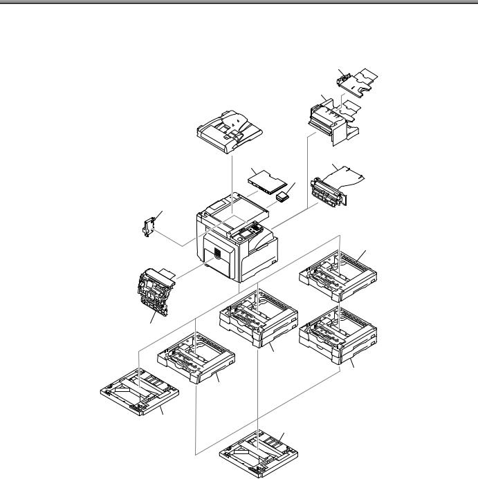
Chapter 1
1.1.2 Pickup/Delivery/Original Handling Accessories System Configuration (iR2018i) iR2018i
The configuration is as shown in the following figure:
[2]
[1]
[3]
[9]
[10]
[8]
[4]
[7]
[5]
[5]
[4]
[6]
[6]
[1]Finisher-U2
[2]Additional Finisher Tray-C1
[3]Inner 2-way Tray-E2
[4]Cassette Feeding Module-P1
[5]Cassette Feeding Module-Q1
F-1-2
[6]Cassette Heater Attachment Kit-E1
[7]Duplex Unit-B1 (*1)
[8]Power Supply Kit-Q1
[9]Document Tray-J1
[10]Card Reader-E1
*1. There are models of the standard equipment.
1-2
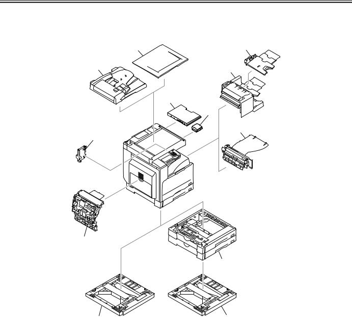
Chapter 1
1.1.3 Pickup/ Delivery /Original Handling Accessories System Configuration (iR2022/iR2022N/iR2025/iR2030) iR2025 / iR2030 / iR2022
The configuration is as shown in the following figure:
[2] |
[4] |
[1] |
[3] |
|
[10]
[11]
[5]
[9]
[8]
[6]
[7] |
[7] |
[1]DADF-P2 (*1)
[2]Platen Cover Type J (*1)
[3]Finisher-U2
[4]Additional Finisher Tray-C1
[5]Inner 2-way Tray-E2
[6]Cassette Feeding Module-Q1
F-1-3
[7]Cassette Heater Attachment Kit-E1
[8]Duplex Unit-B1 (*1)
[9]Power Supply Kit-Q1
[10]Document Tray-J1
[11]Card Reader-E1
*1. There are models of the standard equipment.
1-3
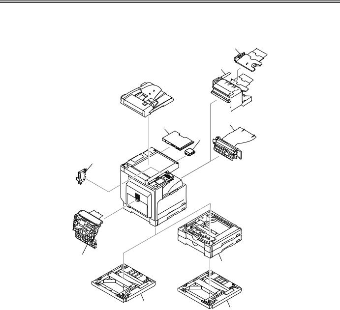
Chapter 1
1.1.4 Pickup/Delivery/Original Handling Accessories System Configuration (iR2022i/iR2022K/iR2025i/iR2030i) iR2022i / iR2025 / iR2030
The configuration is as shown in the following figure:
[2]
[1]
[3]
[8]
[9]
[7]
[6]
[4]
[5]
|
|
|
[5] |
|
|
F-1-4 |
|
[1] |
Finisher-U2 |
[6] |
Duplex Unit-B1 (*1) |
|
|
||
[2] |
Additional Finisher Tray-C1 |
[7] |
Power Supply Kit-Q1 |
|
|
||
[3] |
Inner 2-way Tray-E2 |
[8] |
Document Tray-J1 |
|
|
||
[4] |
Cassette Feeding Module-Q1 |
[9] |
Card Reader-E1 |
|
|
[5]Cassette Heater Attachment Kit-E1
*1. There are models of the standard equipment.
1-4
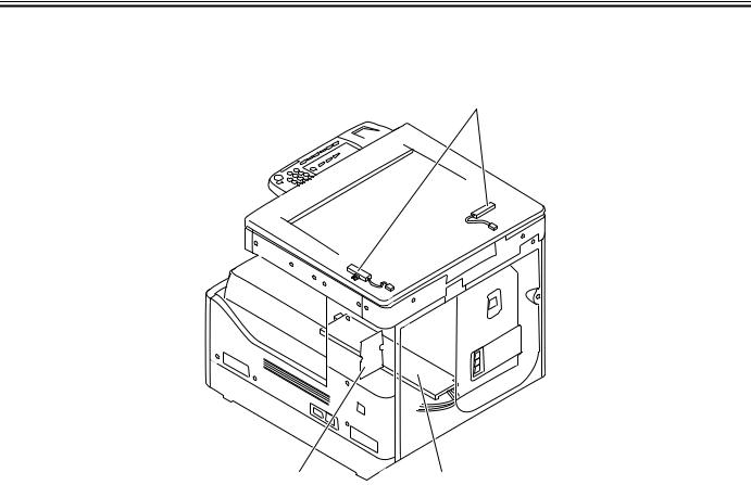
Chapter 1
1.1.5 Reader Heater/Cassette Heater System Configuration (iR2018/iR2022/iR2022N) iR2018 / iR2022
The configuration is as shown in the following figure:
[1]
[3] |
[2] |
F-1-5
[1]Reader Heater (*1)
[2]Cassette Heater (*1)
[3]Heater PCB
*1: To operate the heaters, a heater PCB is required. These parts are supplied as service parts, not the standard items.
1-5
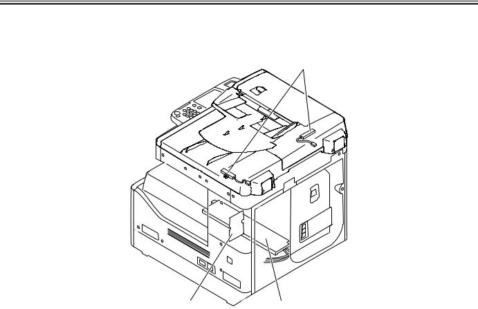
Chapter 1
1.1.6 Reader Heater/Cassette Heater System Configuration (iR2018i) iR2018i
The configuration is as shown in the following figure:
[1]
[3] |
[2] |
F-1-6
[1]Reader Heater (*1)
[2]Cassette Heater (*1)
[3]Heater PCB
*1: To operate the heaters, a heater PCB is required. These parts are supplied as service parts, not the standard items.
1-6
Loading...