

POMPA PER TRAPANO PBMP 30 A1
POMPA PER TRAPANO
Istruzioni per l‘uso
BOHRMASCHINENPUMPE
Bedienungsanleitung
IAN 75640
DRILL PUMP
Operating instructions
Prima di leggere aprire la pagina con le immagini e prendere confi denza
con le diverse funzioni dell’apparecchio.
Before reading, unfold the page containing the illustrations and familiarise
yourself with all functions of the device.
Klappen Sie vor dem Lesen die Seite mit den Abbildungen aus und machen
Sie sich anschließend mit allen Funktionen des Gerätes vertraut.
IT / MT Istruzioni per l‘uso Pagina 1
GB / MT Operating instructions Page 11
DE / AT / CH Bedienungsanleitung Seite 21
A
B

INDICE PAGINA
Introduzione 2
Avvertenze di sicurezza 2
Uso conforme 3
Dati tecnici 3
Dotazione 4
Panoramica dell'apparecchio 4
Materiale di montaggio necessario 4
Montaggio e connessione 5
Smontaggio del codolo motore 7
Uso 8
Pulizia e manutenzione 8
Smaltimento 9
Dichiarazione di conformità 9
Importatore 9
Garanzia e assistenza 10
- 1 -
Introduzione
Congratulazioni!
Con il suo acquisto, ha scelto un prodotto di alta qualità. Si familiarizzi con il
prodotto prima della prima messa in funzione. Legga attentamente il presente
manuale di istruzioni per l'uso. Utilizzi il prodotto solo come descritto e per i
campi di impiego indicati. Conservi con cura il manuale. In caso di cessione
del prodotto a terzi, consegni anche tutta la documentazione relativa.
Avvertenze di sicurezza
Per evitare il rischio di infortuni e danni
all'apparecchio:
• Azionare la pompa solo se bloccata con l'accluso supporto per impedire
eventuali avvolgimenti, torsioni o angolazioni.
• Controllare la pompa prima dell'uso per assicurarsi che sia in perfette
condizioni. La pompa non dev'essere utilizzata in presenza di danni visibili.
L'albero motore della pompa non può essere girato a mano.
Ciò non indica guasti alla pompa.
• Utilizzare solo tubi che sopportino una pressione di almeno 3 bar.
• Controllare che l'attacco dei tubi sia saldamente inserito.
• Impedire la penetrazione di liquidi nel trapano con il quale si aziona la
pompa. In caso ciò avvenga, staccare immediatamente la spina dalla presa.
• Per non danneggiare la pompa, evitare l'aspirazione di sporco grossolano.
All'occorrenza, applicare un filtro al flessibile di aspirazione.
• Questo apparecchio non è indicato per i bambini o per altre persone, le
cui capacità fisiche, sensoriali o psichiche impediscano l'uso sicuro
dell'apparecchio in assenza di aiuto o sorveglianza. Sorvegliare i bambini
per assicurarsi che non giochino con l'apparecchio.
- 2 -

Uso conforme
Questa pompa è prevista per ...
– tradizionali trapani a mano con rotazione a destra/sinistra, con collo da
43 mm di tipo europeo e mandrino a corona dentata/a serraggio rapido
o mandrino con alloggiamento SDS, fino a un numero di giri di 3400
g/min,
– per pompare liquidi freddi o a temperatura fino a 40°C, come ad es.
acque di consumo o reflue derivanti da acquari o stagni.
Questa pompa
– pompare liquidi infiammabili, esplosivi, velenosi, corrosivi o alimentari.
– a fini industriali o commerciali.
nnoonn
è prevista per ...
Dati tecnici
Portata: max. 2,4 m3/h
Attacco tubo: 3/4” (19 mm)
Pressione: max. 3 bar
Altezza di portata: max. 30 m
Altezza di aspirazione: max. 3 m
Temperatura del liquido di trasporto: max. 40°C
Tempo di ciclo a secco: max. 12 secondi
Numero di giri: max. 3400 g/min
- 3 -

Dotazione
- Pompa
- Codolo corto
- Codolo lungo
- Morsetto di fissaggio
- Supporto
- Chiave per viti a brugola
- Cassetta di conservazione per codoli motore e chiavi per viti a brugola
- Le presenti istruzioni per l'uso
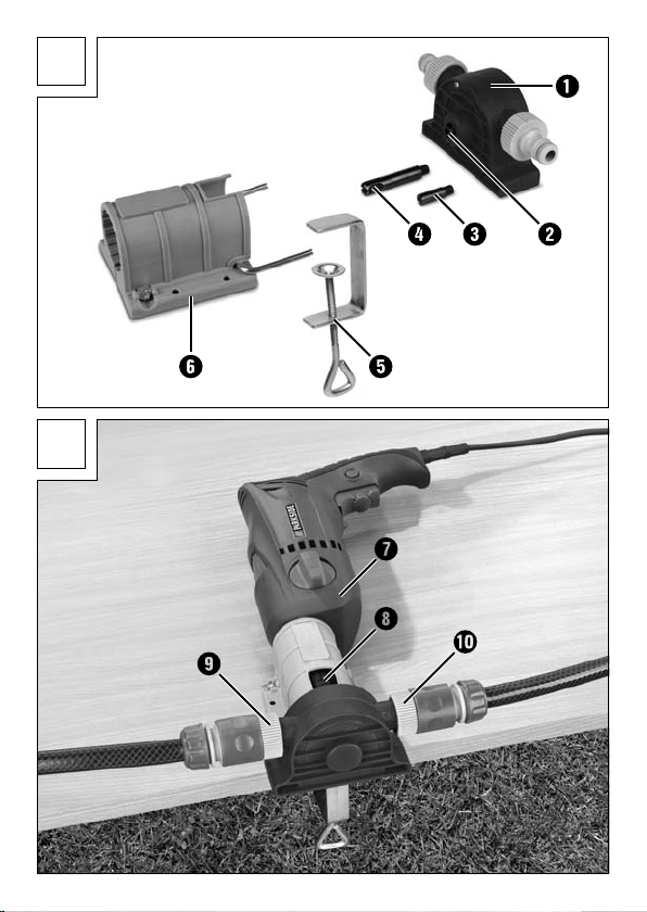
Panoramica dell'apparecchio
Figura A:
Pompa
q
Albero motore della pompa
w
Codolo motore corto (indicate per il mandrino a corona dentata/
e
a serraggio rapido)
Codolo motore lungo (indicato per alloggiamento SDS)
r
Fissaggio a morsetto
t
Supporto
y
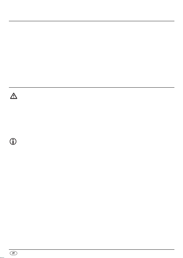
Figura B:
Trapano (non in dotazione)
u
Cavità per la chiavetta per mandrino
i
Attacco flessibile di aspirazione
o
Attacco flessibile pneumatico
a
Materiale di montaggio necessario
- Cacciavite a stella
- Cacciavite a lama
- Chiave fissa (inclusa nella fornitura)
- 4 -

Montaggio e connessione
Montare il supporto
come indicato nell'immagine B.
In alternativa, il supporto
piano di lavoro (materiale di montaggio non incluso nella fornitura).
con il fissaggio a morsetto tsu un piano di lavoro,
y
può anche essere montato tramite viti su un
y
Se si utilizza un mandrino a corona dentata e un codolo
corto e...
Avvitare il codolo motore corto
Inserire il trapano
con il mandrino nel supporto y.
u
Spingere quindi la pompa
motore
no nei fori di levata della pompa
sporga entro il mandrino, e i perni del fissaggio ysi inserisca-
e
sull'albero motore wdella pompa q.
e
sul supporto yin modo tale che il codolo
q
.
q
Avvitare saldamente il mandrino con l'apposita chiave attraverso l'intaglio
, in modo che la pompa qnon possa più staccarsi dal supporto y.
i
Avvitare saldamente la vite con la testa a croce sul supporto
dire che il trapano
Connettere il tubo di aspirazione al raccordo
raccordo
sulla pompa
Se si utilizza un mandrino a serraggio rapido e un codolo corto e...
. In tal caso rispettare la direzione del flusso indicata
a
q
Fissare il codolo
Montare il trapano
supporto
y
.
Avvitare saldamente la vite a croce del supporto
trapano
possa spostarsi.
u
possa spostarsi.
u
e il tubo a pressione al
o
.
nel mandrino.
e
, con il codolo già inserito enel mandrino, nel
u
, in modo che il
y
, per impe-
y
- 5 -

Spingere la pompa
sporga entro la filettatura dell'albero di trasmissione we i perni del supporto
si inseriscano nei fori di alloggiamento della pompa q.
y
Lasciare il trapano
minimo e avvicinare la pompa
alla pompa
q
Collegare il flessibile di aspirazione all'attacco
all'attacco
. Rispettare la direzione del flusso indicata sulla pompa q.
a
sul supporto yin modo tale che il codolo
q
in modalità rotazione a destra, attivarlo al regime
u
al codolo e. Il codolo eviene fissato
q
.
e il flessibile pneumatico
o
e
Se si utilizza un mandrino con alloggiamento SDS e un
codolo lungo r...
Fissare il codolo motore lungo
Inserire il trapano
nel supporto
, con il codolo motore rpremontato nel mandrino,
u
.
y
Avvitare saldamente la vite con la testa a croce sul supporto
che il trapano
Spingere la pompa
sporga entro la filettatura dell'albero di trasmissione w, e i perni del supporto
y
Fare girare il trapano
are la pompa
viene così fissato alla pompa q.
urti.
u
sul supporto yin modo tale che il codolo motore
q
si inseriscano nei fori di alloggiamento della pompa q.
verso destra con un numero di giri basso, e port-
u
direttamente sul codolo motore r. Il codolo motore
q
Connettere il tubo di aspirazione al raccordo
raccordo
sulla pompa
. In tal caso rispettare la direzione del flusso indicata
a
.
q
nel mandrino.
r
, per impedire
y
e il tubo a pressione al
o
r
r
- 6 -

Smontaggio del codolo motore
Smontaggio del codolo motore corto
Mandrino a corona dentata
e
Aprire il mandrino con l'apposita chiave attraverso l'intaglio
la pompa
Avvitare il codolo motore corto
e chiave fissa dalla pompa
Mandrino a serraggio rapido
Con la chiave per viti a brugola, attraverso la cavità
motore
Lasciare il trapano
minimo. Il codolo
Rimuovere la pompa
Rimuovere il codolo
Smontaggio del codolo motore lungo
Mandrino con alloggiamento SDS
Con la chiave fissa, attraverso l'intaglio
pompa
Fare girare il trapano
Il codolo motore
Rimuovere la pompa
Rimuovere il codolo motore
dal supporto y.
q
della pompa q.
w
e
.
q
r
con l'aiuto di un cacciavite a lama
e
.
q
i
in modalità rotazione a sinistra e attivarlo al regime
u
viene rilasciato dalla pompa q.
dal supporto y.
q
dal mandrino.
e
r
fissare l'albero motore walla
i
a sinistra a basso numero di giri.
u
viene così staccato dalla pompa q.
dal supporto y.
q
dal mandrino.
r
e prelevare
i
, fissare l'albero
- 7 -

Uso
Attenzione!
La pompa è del tipo ad autoaspirazione. Se la pompa non aspira qentro
12 secondi, spegnere subito il trapano
motivo, non consentire l'avvio della pompa
chiuso dal lato dello scarico.
Collegare l'estremità aperta del flessibile di aspirazione nel liquido da
aspirare. Il flessibile di aspirazione non deve essere più lungo di 3 m.
Prestare attenzione che il flessibile di aspirazione non aspiri aria.
per evitare il grippaggio. Per tale
u
se il flessibile pneumatico è
q
Se la pompa
po' di liquido e sollevarlo affinché il liquido raggiunga la pompa.
Fare quindi azionare dal trapano
sorveglianza, per reagire rapidamente in caso di rischi. Fare inoltre anche
attenzione al fatto che il trapano
trapanatura. Qualora il numero di giri del trapano
è possibile regolare in tal modo la portata.
non aspira, riempire il flessibile di aspirazione con un
q
la pompa q, tuttavia sempre sotto
u
giri verso destra, come avviene per la
u
sia regolabile,
u
Spegnere subito il trapano, non appena aspira a vuoto.
Pulizia e manutenzione
Pulire la pompa qsolo con un panno asciutto o leggermente inumidito.
Non utilizzare solventi o abrasivi, per non danneggiare le superfici in plastica.
La pompa non necessita di manutenzione.
- 8 -

Smaltimento
Non gettare per alcun motivo l'apparecchio insieme ai normali rifiuti domestici.
Smaltire l'apparecchio attraverso un'azienda di smaltimento autorizzata o attraverso l'ente di smaltimento comunale. Rispettare le prescrizioni attualmente in vigore. In caso di dubbi mettersi in contatto con l'ente di smaltimento competente.
Smaltire tutti i materiali dell'imballaggio in modo ecocompatibile.
Dichiarazione di conformità
Kompernaß Handelsgesellschaft GmbH, Burgstraße 21, D-44867 Bochum
dichiara sotto la propria responsabilità che il prodotto risponde a tutti i requisiti della Direttiva macchine: 2006/42 EC.
Tipo/contrassegno apparecchio: Powerfix Profi Plus Pompa per trapano
PBMP 30 A1
Numero di serie: IAN 75640
Anno di produzione: 05/2012
Bochum, 10.05.2012
Semi Uguzlu, Direttore del Reparto Qualità
Importatore
KOMPERNASS GMBH
BURGSTRASSE 21
44867 BOCHUM, GERMANY
www.kompernass.com
- 9 -

Garanzia e assistenza
Questo apparecchio è garantito per tre anni a partire dalla data di acquisto.
L'apparecchio è stato prodotto con cura e debitamente collaudato prima della consegna. Conservare lo scontrino come prova d'acquisto. In caso di interventi in garanzia, contattare telefonicamente il proprio centro di assistenza.
Solo in questo modo è possibile garantire una spedizione gratuita della merce.
La garanzia vale solo per i difetti di materiale o fabbricazione, non per i danni da trasporto, parti soggette a usura o danni a parti fragili come ad es. interruttori o accumulatori. Il prodotto è destinato esclusivamente all'uso domestico e non a quello commerciale.
La garanzia decade in caso di impiego improprio o manomissione, uso della
forza e interventi non eseguiti dalla nostra filiale di assistenza autorizzata.
Questa garanzia non costituisce alcun limite ai diritti legali del consumatore.
Il periodo di garanzia non viene prolungato in caso di un intervento in garanzia. Ciò vale anche per le componenti sostituite e riparate. I danni e difetti
presenti già all'acquisto devono essere comunicati immediatamente dopo il
disimballaggio, e non oltre due giorni dalla data di acquisto. Le riparazioni
effettuate dopo la scadenza del periodo di garanzia sono a pagamento.
Assistenza Italia
Tel.: 02 36003201
E-Mail: kompernass@lidl.it
IAN 75640
Assistenza Malta
Tel.: 80062230
E-Mail: kompernass@lidl.com.mt
IAN 75640
- 10 -

CONTENT PAGE
Introduction 12
Safety instructions 12
Intended Usage 13
Technical Data 13
Items supplied 14
Overview of the appliance 14
Assembly material required 14
Assembly and connection 15
Disassembly of the drive shaft 17
Utilisation 18
Cleaning and care 18
Disposal 19
Declaration of conformity 19
Importer 19
Warranty and Service 20
- 11 -

Introduction
Congratulations!
With your purchase you have decided in favour of a quality product. Familiarise
yourself with the product before taking it into use. To do this, read the following
operating instructions attentively. Use the product only as described and only
for the specified areas of application. Retain these instructions for future reference. In addition, pass these documents on, together with the product, to any
future owner.
Safety instructions
To avoid the risk of accidents and damage to the
appliance:
• Operate the pump ONLY when it is secured by the supplied mounting
against jolting, twisting and canting.
• Check the pump for a faultfree condition before ever taking it into use.
The pump may not be used if it shows signs of damage.
The drive shaft of the pump does not allow itself to be turned by hand.
This does not indicate that the pump is defective.
• Use only hoses certified as being able to withstand a pressure of at least
3 bars (44 psi).
• Check the plug-in connectors on the hoses for firm seating.
• Take steps to ensure that the fluid being pumped cannot come into contact
with the electric drill during pumping. Should it nonetheless occur, immediately remove the power plug.
• Avoid the intake of coarse dirt, otherwise the pump could be damaged.
If needs be, use a filter on the suction hose.
- 12 -

• This appliance is not intended for use by children or other individuals whose
physical, sensorial or intellectual abilities prevent safe usage of the appliance should they not receive support or supervision in the correct operation of the appliance. Children should be supervised to ensure that they do
not play with the appliance.
Intended Usage
This pump is intended for ...
– standard commercial right/left rotating electric drills with a 43 mm Euro-
spindle and a gear-wheel rim chuck/quick-release chuck or drill chuck
with SDS fitting, up to rotation speed of 3400 rpm,
– the pumping of cold or up to 40°C warm fluids, such as non-potable or
dirty water from fish tanks or ponds.
This pump is
– the pumping of flammable, explosive, poisonous or caustic liquids or
foodstuffs.
– for industrial or commercial applications.
NNOOTT
intended for ...
Technical Data
Capacity: max. 2,4 m3/h
Hose connection: 3/4” (19 mm)
Pressure: max. 3 bar
Delivery height: max. 30 m
Suction height: max. 3 m
Temperature of the fluid being pumped: max. 40°C
Dry run time: max. 12 seconds
Rotation speed: max. 3400 rpm
- 13 -

Items supplied
- Pump
- Short drive shaft
- Long drive shaft
- Clamp fixing
- Mounting
- Open-ended spanner
- Storage box for the drive shafts and open-ended spanner
- This operating manual
Overview of the appliance
Figure A:
Pump
q
Drive shaft of the pump
w
Short drive shaft (suitable for gear-wheel/quick-release chuck)
e
Long drive shaft (suitable for a drill chuck with SDS fitting)
r
Clamp fastening
t
Mounting
y
Figure B:
Electric drill (not supplied)
u
Recess for chuck key
i
Connection for suction hose
o
Connection for pressure hose
a
Assembly material required
- Philips-type screwdriver
- Flat-headed screwdriver
- Open-ended spanner (supplied)
- 14 -

Assembly and connection
Assemble the mounting
as shown in figure B.
Alternatively, the mounting
with screws (assembly material not supplied).
with the clamp fastening tonto a work surface,
y
can also be secured to a work surface
y
When using a gear-wheel chuck and the short drive
shaft e...
Screw the short drive shaft
Insert the electric drill
Now push the pump
projects into the chuck and the pins of the mounting yare located in the
reception holes on the pump
q
Now tighten the chuck with the chuck key through the recess
that the pump
can no longer release itself from the mounting y.
q
Tighten the cross-headed screw on the mounting
cannot jolt around.
u
Attach the suction hose to the connection
connection
pump
. Pay heed to the direction of flow detailed on the
a
.
q
onto the drive shaft wof the pump q.
e
with the chuck into the mounting y.
u
onto the mounting yso that the drive shaft
.
q
i
firmly, so that the drill
y
and the pressure hose to the
o
so firmly
When using a quick-release chuck and the short drive
shaft e...
Secure the short drive shaft
Insert the electric drill
chuck, into the mounting
u
Securely tighten the cross-head screw on the mounting
is being firmly held.
into the chuck.
e
, with the pre-assembled drive shaft ein the
.
y
so that the drill
y
e
u
- 15 -

Now push the pump
projects into the thread of the drive shaft w, and the pins of the mounting
are located in the reception holes on the pump q.
y
Let the drill
and then guide the pump
shaft
e
start to run in a clockwise rotation and at low revolutions
u
is thereby secured to the pump q.
Attach the suction hose to the connection
connection
pump
. Pay heed to the direction of flow detailed on the
a
.
q
onto the mounting yso that the drive shaft
q
straight onto the drive shaft e. The drive
q
and the pressure hose to the
o
e
When using a chuck with SDS fitting and the long drive
shaft r...
Attach the long drive shaft
Insert the electric drill
chuck, into the mounting
Tighten the cross-headed screw on the mounting
cannot jolt around.
Now push the pump
projects into the thread of the drive shaft wand the pins of the mounting
are located in the reception holes on the pump q.
y
q
Allow the electric drill
ons and guide the pump
drive shaft
will be fixated onto the pump q.
r
Attach the suction hose to the connection
connection
pump
. Pay heed to the direction of flow detailed on the
a
.
q
into the chuck.
r
, with the pre-assembled drive shaft rin the
u
.
y
firmly, so that the drill
y
onto the mounting yso that the drive shaft
to run with a clockwise rotation and low revoluti-
u
straight on to the drive shaft r. With this the
q
and the pressure hose to the
o
r
u
- 16 -

Disassembly of the drive shaft
Disassembly of the short drive shaft
Wheel rim chuck
e
Open the chuck with the chuck key through the recess
the pump
Unscrew the short drive shaft
the open-ended spanner from the pump
Quick-release chuck
Using the open-ended spanner through the recess
drive shaft
Allow the electric drill
volutions. The drive shaft
Remove the pump
Remove the drive shaft
Disassembly of the long drive shaft
Chuck with SDS fitting
from the mounting y.
q
of the pump q.
w
to run with an anti-clockwise rotation and low re-
u
e
from the mounting y.
q
from the chuck.
e
by using a cross-headed screwdriver and
e
.
q
i
is thereby released from the pump q.
r
Using the open-ended spanner through the recess,
drive shaft
Allow the electric drill
revolutions. With this the drive shaft
Remove the pump
Remove the drive shaft
of the pump q.
w
q
to run with an anti-clockwise rotation and low
u
will be released from the pump q.
r
from the mounting y.
from the chuck.
r
and then remove
i
, counter screw the
counter screw the
i
- 17 -

Utilisation
Attention!
The pump is self priming. If the pump qdoes not start to suck up within 12
seconds, turn the drill
son, do not allow the pump
the discharge side is closed.
Place the open end of the suction hose into the liquid that is to be pumped.
The suction hose may not be longer than 3 m. Ensure that the suction hose
does not pull in air.
off immediately to avoid seizure. For this same rea-
u
to commence suction if the pressure hose on
q
If the pump
and then lift it so that the liquid runs before the pump.
Allow the drill
so that you can react quickly in the event of danger. Absolutely ensure
that the electric drill
Should the rotation speed of the electric drill
use this to regulate the discharge flow.
does not commence suction, fill the hose with some water
q
, now the pump q, to start-up – but not without supervision,
u
is rotating to the right, as with normal drilling.
u
be adjustable, you can
u
Turn the drill off immediately after the container is empty.
Cleaning and care
Clean the pump qwith a dry or lightly moistened cloth only. To avoid damage
to the plastic surfaces, do not use solvents or abrasive cleaning agents.
The pump is maintenance free.
- 18 -
Disposal
Do not dispose of the appliance in your normal domestic waste.
Dispose of the appliance through an approved disposal centre or at your
community waste facility. Observe the currently applicable regulations. In
case of doubt, please contact your waste disposal centre.
Dispose of all packaging materials in an environmentally friendly
manner.
Declaration of conformity
We, Kompernaß Handelsgesellschaft GmbH, Burgstraße 21, D-44867 Bochum
declare under our sole responsibility that this product complies with all requirements of the Machinery Directive: 2006/42/EC.
Type/Appliance Designation: Powerfix Profi Plus Drill Pump PBMP 30 A1
Serial number: IAN 75640
Year of manufacture: 05/2012
Bochum, dated 10.05.2012
Semi Uguzlu, Quality Manager
Importer
KOMPERNASS GMBH
BURGSTRASSE 21
44867 BOCHUM, GERMANY
www.kompernass.com
- 19 -
Warranty and Service
The warranty for this appliance is for 3 years from the date of purchase. The
appliance has been manufactured with care and meticulously examined before delivery. Please retain your receipt as proof of purchase. In the event of
a warranty claim, please make contact by telephone with our Service Department. Only in this way can a post-free despatch for your goods be assured.
The warranty covers only claims for material and manufacturing defects, but
not for transport damage, for wearing parts or for damage to fragile components, e.g. buttons or batteries. This product is for private use only and is not
intended for commercial use. The warranty is void in the case of abusive and
improper handling, use of force and internal tampering not carried out by our
authorized service branch. Your statutory rights are not restricted in any way
by this warranty.
The warranty period will not be extended by repairs made under warranty.
This applies also to replaced and repaired parts. Any damage and defects
extant on purchase must be reported immediately after unpacking the appliance, at the latest, two days after the purchase date. Repairs made after the
expiration of the warranty period are subject to payment.
Service Great Britain
Tel.: 0871 5000 720 (£ 0.10/Min.)
E-Mail: kompernass@lidl.co.uk
IAN 75640
Service Malta
Tel.: 80062230
E-Mail: kompernass@lidl.com.mt
IAN 75640
- 20 -

INHALTSVERZEICHNIS SEITE
Einführung 22
Sicherheitshinweise 22
Bestimmungsgemäßer Gebrauch 23
Technische Daten 23
Lieferumfang 24
Geräteübersicht 24
Benötigtes Montagematerial 24
Montage und Anschluss 25
Demontage des Antriebsschafts 27
Verwenden 28
Reinigen und Warten 28
Entsorgen 29
Konformitätserklärung 29
Importeur 29
Garantie und Service 30
- 21 -
Einführung
Herzlichen Glückwunsch!
Mit Ihrem Kauf haben Sie sich für ein hochwertiges Produkt entschieden.
Machen Sie sich vor der ersten Inbetriebnahme mit dem Produkt vertraut.
Lesen Sie hierzu aufmerksam die nachfolgende Bedienungsanleitung. Benutzen
Sie das Produkt nur wie beschrieben und für die angegebenen Einsatzbereiche.
Bewahren Sie diese Anleitung gut auf. Händigen Sie alle Unterlagen bei
Weitergabe des Produkts an Dritte ebenfalls mit aus.
Sicherheitshinweise
Um Unfallgefahr und Geräteschäden zu vermeiden:
• Betreiben Sie die Pumpe nur, wenn sie mit der beiliegenden Halterung
gegen Herumschlagen, Verdrehen oder Verkanten gesichert ist.
• Kontrollieren Sie die Pumpe auf einwandfreien Zustand vor jedem
Gebrauch. Die Pumpe darf nicht verwendet werden, wenn Schäden
erkennbar sind.
Die Antriebswelle der Pumpe läßt sich nicht mit der Hand drehen.
Dies deutet nicht auf einen Defekt der Pumpe hin.
• Verwenden Sie nur Schläuche, die bis mindestens 3 bar druckfest sind.
• Kontrollieren Sie die Steckverbinder an den Schläuchen auf festen Sitz.
• Sorgen Sie dafür, dass keine Flüssigkeiten an die Bohrmaschine gelangen
können, mit der Sie die Pumpe antreiben. Falls doch, ziehen Sie sofort den
Netzstecker.
• Vermeiden Sie das Ansaugen von groben Schmutz, da sonst die Pumpe
beschädigt werden kann. Verwenden Sie ggf. einen Filter am Ansaugschlauch.
- 22 -

• Dieses Gerät ist nicht für Kinder oder andere Personen geeignet, deren
physische, sensorische oder geistige Fähigkeiten ohne Unterstützung oder
Aufsicht eine sichere Nutzung des Gerätes verhindern. Kinder sollten
beaufsichtigt werden, um sicherzustellen, dass sie nicht mit dem Gerät spielen.
Bestimmungsgemäßer Gebrauch
Diese Pumpe ist vorgesehen für ...
– handelsübliche Rechts/Links drehende Handbohrmaschinen mit 43 mm
Eurohals und Zahnkranzfutter/Schnellspannfutter oder Bohrfutter mit SDSAufnahme, bis zu einer Drehzahl von 3400 U/min,
– zum Pumpen von kalten oder bis zu 40°C warmen Flüssigkeiten,
wie z.B. Brauch- oder Schmutzwasser aus Aquarien oder Teichen.
Diese Pumpe ist
– zum Pumpen von brennbaren, explosiven, giftigen oder ätzenden
Flüssigkeiten oder Lebensmitteln.
– für industrielle oder gewerbliche Zwecke.
nniicchhtt
vorgesehen ...
Technische Daten
Fördermenge: max. 2,4 m3/h
Schlauchanschluss: 3/4” (19 mm)
Druckleistung: max. 3 bar
Förderhöhe: max. 30 m
Ansaughöhe: max. 3 m
Temperatur der
Förderflüssigkeit: max. 40°C
Trockenlaufzeit: max. 12 Sekunden
Drehzahl: max. 3400 U/min
- 23 -

Lieferumfang
- Pumpe
- Antriebsschaft kurz
- Antriebsschaft lang
- Klemmbefestigung
- Halterung
- Maulschlüssel
- Aufbewahrungsbox für die Antriebsschäfte und Maulschlüssel
- Diese Bedienungsanleitung
Geräteübersicht
Abbildung A:
Pumpe
q
Antriebswelle der Pumpe
w
Antriebsschaft kurz (geeignet für Zahnkranz-/Schnellspannbohrfutter)
e
Antriebsschaft lang (geeignet für SDS-Aufnahme)
r
Klemmbefestigung
t
Halterung
y
Abbildung B:
Bohrmaschine (nicht im Lieferumfang enthalten)
u
Aussparung für Bohrfutterschlüssel
i
Anschluss Ansaugschlauch
o
Anschluss Druckschlauch
a
Benötigtes Montagematerial
- Kreuzschlitzschraubendreher
- Schlitzschraubendreher
- Maulschlüssel (im Lieferumfang enthalten)
- 24 -

Montage und Anschluss
Montieren Sie die Halterung
Arbeitsplatte, wie in Abbildung B gezeigt.
Alternativ kann die Halterung
Arbeitsplatte montiert werden (Montagematerial nicht im Lieferumfang
enthalten).
mit der Klemmbefestigung tauf einer
y
auch mittels Schrauben auf einer
y
Bei Verwendung eines Zahnkranzbohrfutters und des
kurzen Antriebsschafts e...
Schrauben Sie den kurzen Antriebsschaft
Pumpe
Stecken Sie die Bohrmaschine
Schieben Sie nun die Pumpe
Antriebsschaft
in den Aufnahmelöchern an der Pumpe qstecken.
q
.
mit dem Bohrfutter in die Halterung y.
u
so auf die Halterung y, dass der
q
in das Bohrfutter ragt, und die Stifte von der Halterung
e
auf die Antriebswelle wder
e
Drehen Sie das Bohrfutter mit dem Bohrfutterschlüssel durch die
Aussparung
Halterung
Drehen Sie die Kreuzschlitzschraube an der Halterung
damit die Bohrmaschine
Schließen Sie den Ansaugschlauch an den Anschluss
Druckschlauch an den Anschluss
angegebene Flussrichtung auf der Pumpe
Bei Verwendung eines Schnellspannbohrfutters und des
kurzen Antriebsschafts e...
Befestigen Sie den kurzen Antriebsschaft
Stecken Sie die Bohrmaschine
im Bohrfutter, in die Halterung y.
Drehen Sie die Kreuzschlitzschraube an der Halterung
damit die Bohrmaschine
so fest, dass die Pumpe qsich nicht mehr aus der
i
lösen kann.
y
nicht herumschlagen kann.
u
an. Beachten Sie dabei die
a
.
q
im Bohrfutter.
e
, mit dem vormontierten Antriebsschaft
u
nicht herumschlagen kann.
u
- 25 -
y
und den
o
y
fest,
fest,
y
e

Schieben Sie die Pumpe
schaft
Halterung
in das Gewinde der Antriebswelle wragt, und die Stifte der
e
in den Aufnahmelöchern der Pumpe qstecken.
y
Lassen Sie die Bohrmaschine
anlaufen und führen Sie die Pumpe
Der Antriebsschaft
e
Schließen Sie den Ansaugschlauch an den Anschluss
Druckschlauch an den Anschluss
angegebene Flussrichtung auf der Pumpe
so auf die Halterung y, dass der Antriebs-
q
im Rechtslauf und mit niedriger Drehzahl
u
gerade auf den Antriebsschaft e.
q
wird dadurch an der Pumpe qbefestigt.
und den
o
an. Beachten Sie dabei die
a
.
q
Bei Verwendung eines Bohrfutters mit SDS-Aufnahme
und des langen Antriebsschafts r...
Befestigen Sie den langen Antriebsschaft
Stecken Sie die Bohrmaschine
im Bohrfutter, in die Halterung y.
, mit dem vormontierten Antriebsschaft
u
Drehen Sie die Kreuzschlitzschraube an der Halterung
damit die Bohrmaschine
Schieben Sie die Pumpe
schaft
Halterung
in das Gewinde der Antriebswelle wragt, und die Stifte der
r
in den Aufnahmelöchern der Pumpe qstecken.
y
Lassen Sie die Bohrmaschine
anlaufen und führen Sie die Pumpe
Der Antriebsschaft
r
nicht herumschlagen kann.
u
so auf die Halterung y, dass der Antriebs-
q
im Rechtslauf und mit niedriger Drehzahl
u
q
wird dadurch an der Pumpe qbefestigt.
Schließen Sie den Ansaugschlauch an den Anschluss
Druckschlauch an den Anschluss
angegebene Flussrichtung auf der Pumpe
a
im Bohrfutter.
r
fest,
y
gerade auf den Antriebsschaft r.
und den
o
an. Beachten Sie dabei die
.
q
r
- 26 -

Demontage des Antriebsschafts
Kurzen Antriebsschaft edemontieren
Zahnkranzbohrfutter
Öffnen Sie das Bohrfutter mit dem Bohrfutterschlüssel durch die
Aussparung
Schrauben Sie den kurzen Antriebsschaft
bendrehers und dem Maulschlüssel von der Pumpe
Schnellspannbohrfutter
Kontern Sie mit dem Maulsschlüssel durch die Aussparung
Antriebswelle
Lassen Sie die Bohrmaschine
anlaufen. Der Antriebsschaft
Entnehmen Sie die Pumpe
Entnehmen Sie den Antriebsschaft
Langen Antriebsschaft rdemontieren
Bohrfutter mit SDS-Aufnahme
Kontern Sie mit dem Maulsschlüssel durch die Aussparung
Antriebswelle
Lassen Sie die Bohrmaschine
anlaufen. Der Antriebsschaft
Entnehmen Sie die Pumpe
Entnehmen Sie den Antriebsschaft
und entnehmen Sie die Pumpe qaus der Halterung y.
i
mithilfe eines Schlitzschrau-
e
.
q
i
der Pumpe q.
w
im Linkslauf und mit niedriger Drehzahl
u
wird dadurch von der Pumpe qgelöst.
e
aus der Halterung y.
q
aus dem Bohrfutter.
e
i
der Pumpe q.
w
im Linkslauf und mit niedriger Drehzahl
u
wird dadurch von der Pumpe qgelöst.
r
aus der Halterung y.
q
aus dem Bohrfutter.
r
die
die
- 27 -

Verwenden
Achtung!
Die Pumpe ist selbstansaugend. Wenn die Pumpe qnicht innerhalb von
12 Sekunden ansaugt, schalten Sie die Bohrmaschine
Festlaufen zu vermeiden. Lassen Sie aus diesem Grund auch die Pumpe
nicht fördern, solange der Druckschlauch auf der Auslaufseite verschlossen ist.
Legen Sie das offene Ende vom Ansaugschlauch in die Flüssigkeit, die
angesaugt werden soll. Der Ansaugschlauch darf nicht länger als 3 m
sein. Achten Sie darauf, dass der Ansaugschlauch keine Luft zieht.
sofort ab, um ein
u
q
Sollte die Pumpe
mit etwas Flüssigkeit und heben Sie ihn an, damit die Flüssigkeit vor die
Pumpe läuft.
Lassen Sie die Bohrmaschine
nicht unbeaufsichtigt, um bei Gefahr schnell reagieren zu können. Achten
Sie unbedingt auch darauf, dass die Bohrmaschine
also wie beim Bohren. Falls die Drehzahl der Bohrmaschine
können Sie darüber die Fördermenge regulieren.
nicht ansaugen, befüllen Sie den Ansaugschlauch
q
nun die Pumpe qantreiben – jedoch
u
nach rechts dreht,
u
regelbar ist,
u
Schalten Sie nach dem Leersaugen sofort die Bohrmaschine aus.
Reinigen und Warten
Reinigen Sie die Pumpe qnur mit einem trockenen oder leicht
angefeuchteten Tuch. Verwenden Sie keine Lösungs- oder Scheuermittel,
um die Kunststoffflächen nicht zu beschädigen.
Die Pumpe ist wartungsfrei.
- 28 -
Entsorgen
Werfen Sie das Gerät keinesfalls in den normalen Hausmüll.
Entsorgen Sie das Gerät über einen zugelassenen Entsorgungsbetrieb oder
über Ihre kommunale Entsorgungseinrichtung.
Beachten Sie die aktuell geltenden Vorschriften. Setzen Sie sich im
Zweifelsfall mit Ihrer Entsorgungseinrichtung in Verbindung.
Führen Sie alle Verpackungsmaterialien einer umweltgerechten
Entsorgung zu.
Konformitätserklärung
Wir, Kompernaß Handelsgesellschaft GmbH, Burgstraße 21, D-44867 Bochum,
erklären in alleiniger Verantwortung, dass das Produkt allen Anforderungen
der Maschinenrichtlinie 2006/42/EC entspricht.
Typ/Gerätebezeichnung: Powerfix Profi Plus Bohrmaschinenpumpe PBMP 30 A1
Seriennummer: IAN 75640
Herstellungsjahr: 05/2012
Bochum, den 10.05.2012
Semi Uguzlu, Qualitätsmanager
Importeur
KOMPERNASS GMBH
BURGSTRASSE 21
D-44867 BOCHUM
www.kompernass.com
- 29 -
Garantie und Service
Sie erhalten auf dieses Gerät 3 Jahre Garantie ab Kaufdatum. Das Gerät
wurde sorgfältig produziert und vor Anlieferung gewissenhaft geprüft.
Bitte bewahren Sie den Kassenbon als Nachweis für den Kauf auf. Bitte setzen Sie sich im Garantiefall mit Ihrer Servicestelle telefonisch in Verbindung.
Nur so kann eine kostenlose Einsendung Ihrer Ware gewährleistet werden.
Die Garantieleistung gilt nur für Material- oder Fabrikationsfehler, nicht aber
für Transportschäden, Verschleißteile oder für Beschädigungen an zerbrechlichen Teilen, z. B. Schalter oder Akkus. Das Produkt ist lediglich für den privaten und nicht für den gewerblichen Gebrauch bestimmt.
Bei missbräuchlicher und unsachgemäßer Behandlung, Gewaltanwendung
und bei Eingriffen, die nicht von unserer autorisierten Service-Niederlassung
vorgenommen wurden, erlischt die Garantie. Ihre gesetzlichen Rechte werden durch diese Garantie nicht eingeschränkt.
Die Garantiezeit wird durch die Gewährleistung nicht verlängert. Dies gilt
auch für ersetzte und reparierte Teile. Eventuell schon beim Kauf vorhandene
Schäden und Mängel müssen sofort nach dem Auspacken gemeldet werden,
spätestens aber zwei Tage nach Kaufdatum. Nach Ablauf der Garantiezeit
anfallende Reparaturen sind kostenpflichtig.
Service Deutschland
Tel.: 01805 772 033 (0,14 EUR/Min. aus dem dt. Festnetz,
Mobilfunk max. 0,42 EUR/Min.)
E-Mail: kompernass@lidl.de
IAN 75640
Service Österreich
Tel.: 0820 201 222 (0,15 EUR/Min.)
E-Mail: kompernass@lidl.at
IAN 75640
Service Schweiz
Tel.: 0842 665566 (0,08 CHF/Min., Mobilfunk max. 0,40 CHF/Min.)
E-Mail: kompernass@lidl.ch
IAN 75640
- 30 -

KOMPERNASS GMBH
Burgstraße 21
D-44867 Bochum
www.kompernass.com
Versione delle informazioni · Last Information Update
Stand der Informationen: 05 / 2012
Ident.-No.: PBMP30A1052012-1
IAN 75640
5
 Loading...