


|
|
|
|
|
|
|
|
|
|
|
|
|
|
|
|
|
|
|
|
|
|
|
|
|
|
|
|
|
|
|
|
|
|
|
|
|
|
|
|
|
|
|
|
|
|
|
|
|
|
|
|
|
|
|
|
|
|
|
|
4 |
MULTI-DETECTOR |
||||||||
|
|
|
|
|
|
|
|
|
|
|
|
|
|
|
|
||||
|
|
|
|
KH 3236 |
|
||||
|
|
|
|
|
|
|
|
|
|
KOMPERNASS GMBH
BURGSTRASSE 21 · D-44867 BOCHUM www.kompernass.com
ID-Nr.: KH3236-02/11-V1
IAN: 64194
MULTI-DETECTOR |
DETEKTOR |
Operating instructions |
WIELOFUNKCYJNY |
|
Instrukcja obsługi |
TÖBBFUNKCIÓS |
MULTI DETEKTOR |
DETEKTOR |
Navodila za uporabo |
Használati utasítás |
|
MULTIFUNKČNÍ |
MULTIDETEKTOR |
DETEKTOR |
Návod na obsluhu |
Návod k obsluze |
|
KH 3236
1
 2
2
r |
|
|
|
|
|
|
|
|
3 |
|
t |
||
|
|
|
|
|
|
|
|
|
|||||
|
|
|
|
|
|
|
|
|
4 |
|
|||
|
|
|
|
|
|
|
|
|
|
||||
|
|
|
|
|
|
|
|
|
|
||||
|
|
|
|
|
|
|
|
|
|
|
5 |
|
|
|
|
|
|
|
|
|
|
|
|
|
|
|
|
|
|
|
|
|
|
|
|
|
|
|
|
|
|
e |
|
|
|
|
|
|
|
|
|
||||
w |
|
|
|
|
6 |
|
|
||||||
|
|
|
|
|
|
||||||||
|
|
|
7 |
|
|
||||||||
|
|
|
|
|
|
|
|
|
|
||||
q |
|
|
|
|
|||||||||
|
|
8 |
|
|
|||||||||
|
|
|
|
||||||||||
09
z

CONTENT |
PAGE |
|
|
Intended use |
2 |
|
|
Safety instructions |
2 |
|
|
Technical data |
4 |
|
|
Description of the appliance |
4 |
|
|
Items supplied |
4 |
|
|
Unpacking |
4 |
|
|
Inserting the battery |
5 |
|
|
Measuring distances |
5 |
|
|
Measuring areas |
7 |
|
|
Measuring volumes |
8 |
|
|
Locating concealed objects |
8 |
|
|
Laser marking |
10 |
|
|
Battery display |
11 |
|
|
Cleaning and storage |
11 |
|
|
Disposal |
11 |
|
|
Warranty & Service |
12 |
|
|
Importer |
12 |
Read the operating instructions carefully before using the device for the first time and preserve this booklet for later reference. Pass this manual on to whoever might acquire the device at a future date.
- 1 -

MULTI-DETECTOR KH 3236
Intended use
The Multi-Measurement Detector is designed for the locating of electrical cables, of wood and metal objects, for the projecting of laser lines, for the measuring of areas and volumes as well as for the measuring of distances. The appliance is intended for domestic use only. Do not use it for commercial purposes. A different or any other usage is regarded as unintended use and can lead to damages and injuries. No liabity will be accepted for damage caused by manipulation of the laser equipment, as well as of the ultrasound transmitter/receiver, or through disregard of these safety instructions.
Safety instructions
Optimal and safe working with the multi-detector is only possible if you read these operating and safety instructions completely and strictly follow their instructions.
 Risk of injury!
•Do not use the appliance at locations where there is a risk of fire or explosion, e. g. close to inflammable liquids or gases.
•This appliance is not intended for use by individuals (including children) with restricted physical, physiological or intellectual abilities or deficiences in experience and/or knowledge unless they are supervised by a person responsible for their safety or receive from this person instruction in how the appliance is to be used.
•Children should be supervised to ensure that they do not play with the appliance.
•Exercise caution with the holding pins. They are sharp and can cause injuries.
 Caution regarding damage to the appliance!
•Do not expose the appliance to rainfall. Do not use the appliance in moist or wet environments.
•Do not place objects containing liquids, e. g. flower vases, on the appliance.
•Do not place any open sources of fire, like candles, on the device.
- 2 -
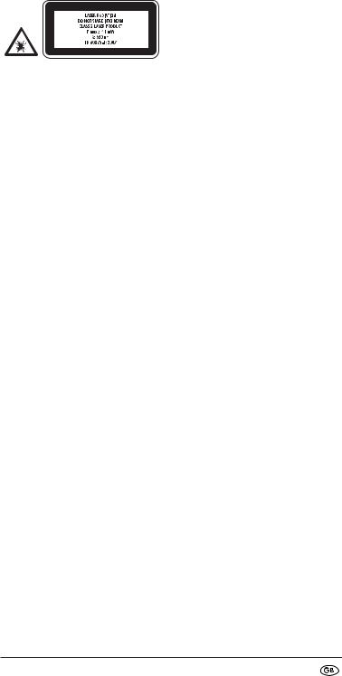
This appliance contains a Class 2 laser. NEVER direct the laser beam at people or animals. NEVER look directly into the laser. The laser can cause serious eye damage.
•Do NOT direct the laser beam at strongly reflective material. Reflected laser beams are also dangerous.
•Do NOT use the appliance to determine the alternating voltage level in exposed or non-insulated power cables.
•Do NOT use the appliance as a substitute for a voltmeter.
 Notes regarding inaccurate measurement results
The appliance does not always recognise all pipes and power cables. The following conditions can contribute to inaccurate results:
–very thick walls
–weak battery
–deeply laid power cables or pipework
–shielded cables
–thick walls with thin pipes or power cables
–walls panelled with metal sheets
–very moist conditions
•This appliance is not suitable for detecting power cables in circuits,
–which are isolated from the mains power supply.
–through which direct current flows.
–which are used for computer or telecommunications systems.
•With this appliance pipework made of plastic or similar materials cannot be detected, only pipework made of metal.
 Interaction with batteries:
•Leaking batteries can cause damage to the appliance. If you do not intend to use the appliance for an extended period, remove the batteries.
•Should the batteries leak, wear protective gloves and clean the battery compartment with a dry cloth.
•Keep batteries away from children. Children can put batteries into their mouths and swallow them. Should a battery ever be swallowed, seek medical attention IMMEDIATELY.
- 3 -

Technical data
Distance measurement by means of Ultrasound
Locating of: |
power cables, metal, wood |
Laser class: |
2 |
Max. output power (P.max): < 1 mW |
|
Wave length (λ): |
650 nm |
|
according EN60825-1:2007 |
Power supply: |
9 V block battery |
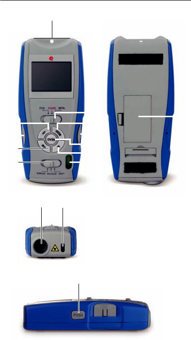
Description of the appliance
1 Measurement point
2Display
3 Material switch (STUD/AC WIRE/METAL)
4Button – MODE
5 Button – Holding pin
6Button – READ
7 Button M (Memory)
8Spirit level
9 Laser beam exit opening
0Ultrasound sender/receiver
q Function switch (LASER/DETECTOR/DISTANCE) w Button – RM (Read Memory)
e Button – Holding pin
rButton +/=
t Battery compartment
zButton – PUSH
Items supplied
•Multi-Detector
•9 V block battery
•Operating instructions
Unpacking
Take the Manifold Measurer from its packaging. Remove all transport restraints and packaging materials. Remove the protective foil from the display 2.
- 4 -

Inserting the battery
1.Open the battery compartment t on the rear side of the Multi-Measurement Detector.
2.Place the 9 V block battery onto the contacts. Pay heed to the correct polarity.
3.Lay the tape for removal of the battery underneath the 9 V block battery and press it into the battery compartment t.
 Important!
Ensure that the wires are not trapped in any way.
This would lead to irreparable damage to the appliance.
4.Close the battery compartment t. The battery compartment lid must close with an audible click.
Measuring distances
1. Slide the function switch q to „DISTANCE“. The display 2 switches itself on.
To switch between the metric and the Anglo-American units of measurement, press and hold the button MODE 4. Then press the button READ 6 and release both buttons simultaneously. When you release the buttons, the measurement units change.
 Note:
Note:
Measurements start at the measurement point 1!
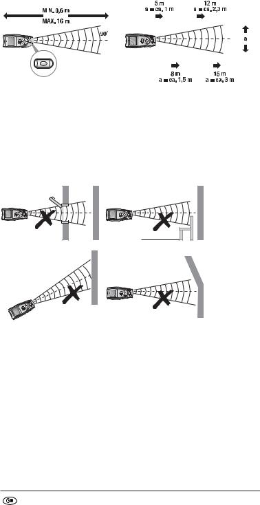
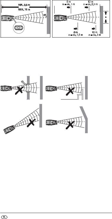
Should the measurement lie outside the measurement range, „Err“ or an illogical number appear in the display. The measurement range lies between 0,6 m (2’) and 16 m (53’).
2.Hold the appliance upright towards the wall to which you wish to measure the distance. The ultrasound sender/receiver 0 must be at a right-angle to the wall. For this, use the spirit level: The bubble in the glass 8 must stand between the marking lines (see Fig. 1).
3.Press the button READ 6. The distance measured appears in the display 2. When you hold the button READ 6 pressed down and slowly move the appliance over the surface to be measured, the appliance continually measures the distances. These are shown on the display 2.
- 5 -
Take note of the following illustrations:
|
|
|
|
|
|
|
|
|
|
|
|
|
|
|
|
|
|
|
|
|
|
|
|
|
|
|
|
|
|
|
|
|
|
|
|
|
|
|
|
|
|
|
|
|
|
|
|
|
|
|
|
|
|
|
|
|
|
|
|
|
|
|
|
|
|
|
|
|
|
|
|
|
|
|
|
|
|
|
|
|
|
|
|
|
|
|
|
|
|
|
|
|
|
|
|
|
|
|
|
|
|
|
|
|
|
|
|
|
|
|
|
|
|
|
|
|
|
|
|
|
|
|
|
|
|
|
|
|
|
|
|
|
|
|
|
|
|
|
|
|
|
|
|
|
|
|
|
|
|
|
|
|
|
|
|
|
|
|
|
|
|
|
|
|
|
|
|
|
|
Fig. 1 |
|
Fig. 2 |
|
|
|
|
||||||||||
The further you are from the wall, the wider is the area (a) that the MultiMeasurement Detector must measure by ultrasound (Fig. 2). Therefore take care that the Manifold Measurer is always directed at a right angle towards a level surface (Fig. 1 and 3). Ensure that there are no objects positioned within the measurement area.
False!
(Fig. 3)
The display illumination glows during the measurement. If a button is not pressed within ca. 15 seconds, the illumination extinguishes. After a further ca. 15 seconds the diplay itself switches off. Press the button READ 6, to reactivate the display and the illumination.
 Note:
Note:
Inaccurate measurements can also occur through a weak battery.
If the battery is too weak, the battery symbol appears in the display.
- 6 -

Adding distances together
You can add the measured distances together:
1.Measure the first distance as described.
2.Press the button +/= r. In the display 2, „+“ appears and the distance measured carries itself over to the lower line.
3.Measure the next distance. The newly measured distance is shown in the upper line.
4.Once again, press the button +/= r. The new measurement is added to the old measurement in the lower line.
5.Repeat steps 2 to 4 to add further measurements.
6.When you wish to leave the addition mode, press the button MODE 4. All values are erased.
Measuring areas
1.Slide the function switch q to „DISTANCE“. The display 2 switches itself on.
2.Press the button MODE 4 once. In the display 2 flashes „L“ (Length).
3.Press the button READ 6, to measure the length. In the upper line the measured length appears and „W“ (Width) starts to flash.
4.Press the button READ 6 to measure the width. The measured width appears on the upper line and the result of the area calculation in the lower line.
Adding areas together
1.Measure an area as described in the section „Measuring areas“.
2.Press the button M 7. „M+“ appears in the display 2. The area measured is now saved.
3.Press the button MODE 4. The appliance is now ready for the second measurement.
4.Measure the next area.
5.Press the button +/= r. A „+“ appears in the display 2.
6.Press the button RM w. The result of the first measurement is shown in the lower line.
7.Press the button +/= r. Both measurements are added together and the result is shown in the lower line.
8.Repeat the steps 2 to 7 to add in further measurement values.
9.When you wish to leave the addition mode, press the button MODE 4. All values are erased.
- 7 -

Measuring volumes
1.Slide the function switch q to „DISTANCE“. The display 2 switches itself on.
2.Press the button MODE 4 twice. In the display 2 flashes „L“ (Length).
3.Press the button READ 6, to measure the length. In the upper line the measured length appears and „W“ (Width) starts to flash.
4.Press the button READ 6 to measure the width. In the upper line the measured width appears and „H“ (Height) starts to flash.
5.Press the button READ 6 to measure the height. The measured height appears in the upper line. In the lower line appears the result of the volume calculation.
Adding volumes together
1.Measure a volume as described in the section „Measuring volumes“.
2.Press the button M 7. „M+“ appears in the display 2. The volume measured is now saved.
3.Press the button MODE 4. The appliance is now ready for the second measurement.
4.Measure the next volume.
5.Press the button +/= r. A „+“ appears in the display 2.
6.Press the button RM w. The result of the first measurement is shown in the lower line.
7.Press the button +/= r. Both measurements are added together and the result is shown in the lower line.
8.Repeat the steps 2 to 7 to add in further measurement values.
9.When you wish to leave the addition mode, press the button MODE 4. All values are erased.
Locating concealed objects
 Notice:
•Before using the appliance for this task, first test it by locating a pipeline or electrical power cable at a known position.
•In cases of doubt, always ask a qualified building contractor.
 Attention!
Should the appliance find a live wire carrying alternating current,
 appears in the display. Under no circumstances should you drill at this location! Danger of electric shock!
- 8 -
The locating of concealed objects is the same in all three modes (STUD = wood, AC WIRE = live electric power cables, METAL = metal).
1.Slide the function switch q to „DETECTOR“.
2.Slide the material switch 3 to STUD, AC WIRE or METAL.
3.First of all, the appliance must be calibrated. Place it flat against the wall where you wish to search for concealed objects.
4.Press and hold the button PUSH z until the signal tone hums. The appliance has now adjusted itself to the wall thickness. Continue to keep the button PUSH z pressed down.
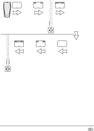
5.Move slowly along the wall with the appliance. As the arrows in the display move closer to the centre of the display, you are getting closer to the concealed object. When the arrows touch and a constant signal tone is heard, mark this position (see Fig. 4).
Fig. 4
6.Now repeat the procedure, but this time approach the object from the other side. As soon as the signal tone sounds, mark this position (see Fig. 4).
The concealed object runs between these two positions.
- 9 -

Locating wood objects
1.Proceed with the search for wood objects as described in the section „Locating concealed objects“.
2.When the Multi-Measurement Detector has found an object, mark it.
To be sure that the object is wood, slide the material switch 3 to METAL.
3.Now search in the same position for metal. Should the Multi-Measurement Detector not find anything, then the object is wood. Should it find something, then the object is metal.
In this case, search again at a different position in the mode „STUD“ and repeat steps 1 to 3.
Laser marking
 The appliance contains a Class 2 laser. NEVER direct the laser beam at people or animals. NEVER look directly into the laser. The laser can cause serious eye damage.
You can use laser marking for the exactly horizontal positioning of pictures, shelves etc.
1.Place the function switch q to „LASER“. A laser line is projected.
Horizontal laser line
 Attention!
Exercise caution with the holding pins. They are sharp and can cause injuries.
1.Hold the Manifold Measurer horizontally against the wall and align it with the assistance of the spirit level 8. The air bubble must stand between the two marking lines.
2.Push both of the holding pins (5 + e) buttons firmly downwards. The pins lightly bore themselves into the wall so that the appliance
does not fall to the floor. The laser throws a horizontal line onto the wall.
 Note:
Note:
The holding pins do not function on stone or metal walls.
The walls must have a soft upper surface.
- 10 -
Vertical laser line
1.Secure a strong thread in the eyelet above the measurement point 1.
2.Hang the Multi-Measurement Detector on the wall at the position where you want to project the vertical line. The Manifold Measurer hangs like a plumbline, perpendicularly downwards. The laser throws a vertical line onto the wall.
Battery display
A battery symbol appears in the display 2 when the battery is weak resp. almost discharged. Replace the battery as soon as possible (see section „Inserting the battery“). If you do not, the measurements will be false.
Cleaning and storage
•Store the appliance at a dry and frost-free location.
•If you do not intend to use the appliance for an extended period, remove the battery from the battery compartment.
•Clean the appliance with a soft, dry cloth.
•Do not use chemical or abrasive cleaning agents. These could damage the housing.
Disposal
Do not dispose of the appliance in your normal domestic waste. This product is subject to the European guideline 2002/96/EC.
Dispose of the appliance through an approved disposal centre or at your community waste facility. Observe the currently applicable regulations. In case of doubt, please contact your waste disposal centre.
Battery disposal!
Batteries may not be disposed of with normal domestic waste. All consumers are statutorily obliged to dispose of batteries at
the collection point in their community/district or with the original supplier. The purpose of this obligation is to ensure that batteries can be disposed of in an environmentally friendly manner. Only dispose of batteries when they are fully discharged.
Dispose of all packaging materials in an environmentally friendly manner.
- 11 -
Warranty & Service
The warranty for this appliance is for 3 years from the date of purchase. The appliance has been manufactured with care and meticulously examined before delivery. Please retain your receipt as proof of purchase. In the event of a warranty claim, please make contact by telephone with our Service Department. Only in this way can a post-free despatch for your goods be assured.
The warranty covers only claims for material and manufacturing defects, but not for transport damage, for wearing parts or for damage to fragile components, e.g. buttons or batteries. This product is for private use only and is not intended for commercial use. The warranty is void in the case of abusive and improper handling, use of force and internal tampering not carried out by our authorized service branch. Your statutory rights are not restricted in any way by this warranty. The warranty period will not be extended by repairs made under warranty. This applies also to replaced and repaired parts. Any damage and defects extant on purchase must be reported immediately after unpacking the appliance, at the latest, two days after the purchase date. Repairs made after the expiration of the warranty period are subject to payment.
Service Great Britain
Tel.: 0871 5000 720 (£ 0.10/Min.)
E-Mail: kompernass@lidl.gb
IAN 64194
Service Ireland
Tel.: 1890 930 034
(0,08 EUR/Min., (peak))
(0,06 EUR/Min., (off peak))
E-Mail: kompernass@lidl.ie
IAN 64194
Importer
KOMPERNASS GMBH BURGSTRASSE 21
44867 BOCHUM, GERMANY
www.kompernass.com
- 12 -

SPIS TREŚCI |
STRONA |
|
|
Zastosowanie zgodnie z przeznaczeniem |
14 |
|
|
Wskazówki bezpieczeństwa |
14 |
|
|
Dane techniczne |
16 |
|
|
Opis urządzenia |
16 |
|
|
Zakres dostawy |
16 |
|
|
Rozpakowanie |
16 |
|
|
Wkładanie baterii |
17 |
|
|
Pomiar odległości |
17 |
|
|
Pomiar powierzchni |
19 |
|
|
Pomiar objętości |
20 |
|
|
Wykrywanie ukrytych obiektów |
20 |
|
|
Wskazywanie laserem |
22 |
|
|
Wskaźnik stanu baterii |
23 |
|
|
Przechowywanie i czyszczenie |
23 |
|
|
Utylizacja |
23 |
|
|
Gwarancja i serwis |
24 |
|
|
Importer |
24 |
Przed pierwszym użyciem zapoznaj się z instrukcją obsługi i zachowaj ją w celu późniejszego wykorzystania. W przypadku przekazania urządzenia osobom trzecim należy przekazać im także instrukcję.
- 13 -

DETEKTOR WIELOFUNKCYJNY KH 3236
Zastosowanie zgodnie z przeznaczeniem
Detektor pomiarowy z laserem jest przeznaczony do lokalizowania przewodów elektrycznych, obiektów metalowych i drewnianych, do rzutowania linii laserowych, do obliczania powierzchni i objętości oraz do pomiaru odległości.
To urządzenie jest przeznaczone wyłącznie do użytku prywatnego. Wykorzystywanie do celów komercyjnych zabronione. Inne lub wykraczające poza ustalone użytkowanie będzie uznawane za niezgodne z przeznaczeniem i może doprowadzić do powstania szkód i obrażeń. Za szkody spowodowane ingerowaniem w układ laserowy, jak również w nadajnik/odbiornik ultradźwięków, jak również nieprzestrzeganiem wskazówek bezpieczeństwa producent nie ponosi żadnej odpowiedzialności.
Wskazówki bezpieczeństwa
Optymalna i bezpieczna praca z wykorzystaniem wykrywacza wielofunkcyjnego jest możliwa tylko z przestrzeganiem wskazówek i informacji podanych w instrukcji użytkowania.
 Zagrożenie odniesieniem obrażeń!
•Nie używaj nigdy urządzenia w miejscach, w których występuje zagrożenie pożaru lub wybuchu, np. w pobliżu łatwopalnych cieczy lub gazów.
•To urządzenie nie jest przystosowane do użytkowania go przez osoby (w tym dzieci) o ograniczonej sprawności umysłowej, czuciowej lub umysłowej, bądź w przypadku niedostatecznego doświadczenia i/lub wiedzy, chyba że będą one znajdowały się pod opieką odpowiedzialnej osoby lub też uzyskają od opiekuna instrukcje, jak należy użytkować urządzenie.
•Nie można pozwolić dzieciom na zabawę urządzeniem.
•Postępuj ostrożnie podczas używania szpilek pomiarowych. Są one bardzo ostre i mogą spowodować obrażenia ciała.
 Ostrzeżenie przed uszkodzeniem urządzenia!
•Nie wystawiaj urządzenia na działanie opadów atmosferycznych. Nie używaj nigdy urządzenia w mokrym lub wilgotnym otoczeniu.
•Nie stawiaj nigdy na urządzeniu naczyń z wodą, np. wazonów na kwiaty.
•Na urządzeniu nie wolno stawiać otwartych źródeł ognia, takich jak np. świece.
- 14 -
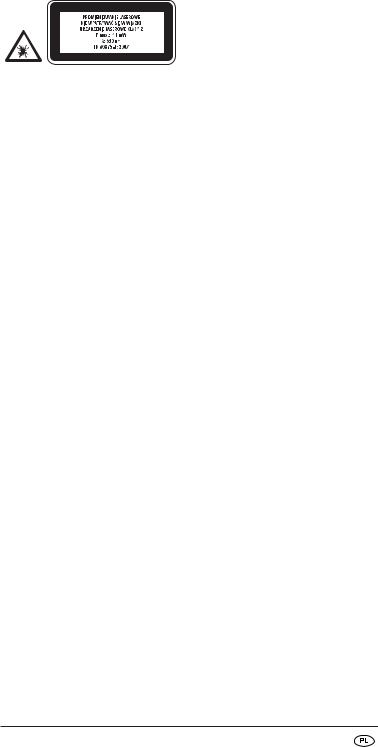
Urządzenie jest wyposażone w laser klasy 2. Nie kieruj nigdy lasera na ludzi lub zwierzęta. Nie patrz nigdy bezpośrednio w laser. Laser może spowodować uszkodzenie wzroku.
•Nie kieruj promienia lasera na przedmioty silnie odbijające promieniowanie. Zagrożenie spowodowane odbitym promieniem lasera.
•Nie używaj urządzenia do sprawdzania napięcia przemiennego w odkrytych wzgl. nieizolowanych przewodach.
•Nie używaj urządzenia jako przyrząd zastępczy zamiast woltomierza.
 Wskazówki dotyczące nieprecyzyjnych wyników pomiaru
Urządzenie nie zawsze wykryje wszystkie rury i przewody.
Następujące warunki mogą spowodować niedokładne rezultaty pomiaru:
–bardzo grube ściany,
–słabe baterie,
–głęboko położene przewody i rury,
–osłonięte kable,
–grube ściany z cienkimi rurami lub przewodami,
–ściany osłonięte płytami metalowymi,
–wilgotne otoczenie.
•To urządzenie nie wykrywa przewodów obwodu elektrycznego,
–izolowanych przed zasilaniem elektrycznym.
–przewodzących prąd stały.
–wykorzystywanych do komputerów lub sieci telefonicznych.
•To urządzenie nie wykrywa rur plastikowych itp., tylko rury z metalu.
 Postępowanie z bateriami:
•Wylane baterie mogą uszkodzić urządzenie. Wyjmij baterie z urządzenia, jeśli zamierzasz go nie używać przez dłuższy czas.
•Komorę zanieczyszczoną rozlanymi bateriami wytrzyj suchą szmatkę. Do pracy zakładaj rękawice ochronne.
•Baterie nie powinny nigdy trafić w ręce dzieci. Dziecko może połknąć baterię. W razie połknięcia baterii, należy niezwłocznie udać się do lekarza.
- 15 -

Dane techniczne
Odległościomierz ultradźwiękowy
Wykrywanie: |
przewodów elektrycznych, metalu, drewna |
Klasa lasera: |
2 |
Maks. moc wyjściowa |
|
(P.maks.): |
< 1mW |
Dł. fal (λ): |
650 nm |
|
zgodnie z normą EN60825-1:2007 |
Zasilanie elektryczne: |
bateria blokowa 9 V |
Opis urządzenia
1 Punkt pomiarowy
2Wyświetlacz
3 Przełącznik materiału (STUD/AC WIRE/METAL)
4Przycisk MODE
5 Przycisk Szpilka pomiarowa
6Przycisk READ
7 Przycisk M (Memory)
8Poziomnica
9Otwór wylotowy lasera
0Nadajnik/odbiornik ultradźwięków
q Przełącznik funkcji (LASER/DETECTOR/DISTANCE) w Przycisk RM (Read Memory)
e Przycisk Szpilka pomiarowa
rPrzycisk +/=
t Komora na baterie
zPrzycisk PUSH
Zakres dostawy
•Detektor wielofunkcyjny
•Bateria blokowa 9 V
•Instrukcja obsługi
Rozpakowanie
Wyjmij detektor pomiarowy z opakowania. Usuń zabezpieczenia transportowe i wszystkie elementy opakowania. Odklej folię z wyświetlacza 2.
- 16 -

Wkładanie baterii
1.Otwórz komorę na baterię t z tyłu detektora pomiarowego.
2.Przyłóż baterię blokową 9 V do styków. Zwróć uwagę na prawidłowe podłączenie biegunów.
3.Podłóż pod baterię blokową 9 V pasek do wyciągania baterii, a następnie wciśnij ją do środka komory t.
 Uwaga!
Uważaj, aby nie zatrzasnąć kabla. Może to doprowadzić do nieodwracalnego uszkodzenia urządzenia.
4.Zamknij komorę na baterię t. Pokrywa musi się zatrzas-nąć z wyraźnym dźwiękiem.
Pomiar odległości
1.Przestaw przełącznik funkcji q w położenie „DISTANCE”. Włącza się wyświetlacz 2.
W celu przełączenia między metrycznym a brytyjskim systemem miar, naciśnij przycisk MODE 4 i przytrzymaj go w tej pozycji.
Następnie naciśnij przycisk READ 6, poczym jednocześnie zwolnij oba przyciski. Jednostki zmieniają się na nowe po zwolnieniu przycisku.
 WSKAZÓWKA:
Pomiar rozpoczyna się od punktu pomiaru 1!
Jeśli pomiar znajdzie się poza zakresem pomiaru, wyświetla się napis „Err” lub nierealna liczba. Zakres pomiaru mieści się między 0,6 m (2 ’) a 16 m (53 ’).
2.Przytrzymaj urządzenie poziomo przed ścianą, do której chcesz zmierzyć odległość. Nadajnik/odbiornik ultradźwięków 0 musi być skierowany pod kątem prostym do ściany. Użyj do tego poziomnicy: Pęcherzyk w poziomnicy 8 musi się znajdować między kreskami (patrz ilustracja1).
3.Naciśnij przycisk READ 6. Na wyświetlaczu 2 wyświetla się zmierzona odległość. Jeśli naciśniesz i przytrzymasz przycisk READ 6, a następnie powoli przesuniesz urządzenie po mie-rzonej powierzchni, odległości będą ciągle mierzone. Są one wyświetlane na wyświetlaczu 2.
- 17 -
Zwróć uwagę na następującą ilustrację: |
|
Ilustracja 1 |
Ilustracja 2 |
Im dalej ściany stoisz, tym szersza jest przestrzeń (a) mierzona przez detektor za pomocą ultradźwięków (ilustracja 2). Zwracaj uwagę, aby detektor pomiarowy był ustawiony zawsze do powierzchni i pod kątem prostym (ilustracja 1 i 3). Zwracaj uwagę, aby w zakresie pomiaru nie znajdowały się żadne przedmioty.
Źle!
Ilustracja 3
W trakcie pomiaru włącza się podświetlenie wyświetlacza. Podświetlenie wyłączy się, jeśli w ciągu 15 sekund nie zostanie naciśnięty żaden przycisk. Po upływie kolejnych około 15 sekund wyłącza się wyświetlacz. Naciśnij przycisk READ 6, aby ponownie włączyć wyświetlacz oraz podświetlenie.
 WSKAZÓWKA:
Wyczerpana bateria jest powodem uzyskiwania niedokładnych pomiarów. Jeśli bateria będzie za słaba, na wyświetlaczy wyświetla się symbol baterii.
- 18 -
Dodawanie odległości
Możesz dodawać do siebie kilka zmierzonych odległości:
1.Zmierz odległość zgodnie z opisem przedstawionym powyżej.
2.Naciśnij przycisk +/= r. Na wyświetlaczu 2 wyświetla się „+”, a zmierzona odległość przechodzi do niższego wiersza.
3.Zmierz następną odległość. Zmierzona na nowo odległość wyświetla się w wierszu górnym.
4.Naciśnij ponownie przycisk +/= r. Nowa wartość pomiarowa zostanie dodana do poprzedniej wartości wyświetlanej w wierszu dolnym.
5.Powtarzaj czynności od kroku 2 do 4 w celu dodania kolejnych odległości.
6.Naciśnij przycisk MODE 4 aby zakończyć tryb dodawania odległości. Wszystkie wartości zostaną skasowane.
Pomiar powierzchni
1.Przestaw przełącznik funkcji q w położenie „DISTANCE”. Włącza się wyświetlacz 2.
2.Naciśnij jeden raz przycisk MODE 4. Na wyświetlaczu miga 2 „L” (Length = długość).
3.Naciśnij przycisk READ 6 aby zmierzyć długość.
W wierszu górnym wyświetla się zmierzona długość i dodatkowo zaczyna migać „W” (Width = szerokość).
4.Naciśnij przycisk READ 6 aby zmierzyć szerokość. W wierszu górnym wyświetla się zmierzona szerokość, a w wierszu dolnym rezultat obliczenia powierzchni.
Dodawanie powierzchni
1.Zmierz powierzchnię, patrz rozdział „Pomiar powierzchni”.
2.Naciśnij przycisk M 7. Na wyświetlaczu 2 wyświetla się „M+”. Zmierzona powierzchnia zostanie zapisana.
3.Naciśnij przycisk MODE 4. Urządzenie jest gotowe do drugiego pomiaru.
4.Zmierz następną powierzchnię.
5.Naciśnij przycisk +/= r. Na wyświetlaczu 2 wyświetla się „+”.
6.Naciśnij przycisk RM w. W wierszu dolnym wyświetla się rezultat pierwszego pomiaru.
7.Naciśnij przycisk +/= r. Oba pomiary zostaną dodane a rezultat wyświetla się w wierszu dolnym.
8.Powtarzaj czynności od kroku 2 do 7 w celu dodania kolejnych odległości.
9.Naciśnij przycisk MODE 4 aby zakończyć tryb dodawania odległości. Wszystkie wartości zostaną skasowane.
- 19 -

Pomiar objętości
1.Przestaw przełącznik funkcji q w położenie „DISTANCE”. Włącza się wyświetlacz 2.
2.Naciśnij dwa razy przycisk MODE 4. Na wyświetlaczu miga 2 „L” (Length = długość).
3.Naciśnij przycisk READ 6 aby zmierzyć długość.
W wierszu górnym wyświetla się zmierzona długość i dodatkowo zaczyna migać „W” (Width = szerokość).
4.Naciśnij przycisk READ 6 aby zmierzyć szerokość. W wierszu górnym wyświetla się zmierzona długość i dodatkowo zaczyna migać „H” (Height = wysokość).
5.Naciśnij przycisk READ 6 aby zmierzyć wysokość.
W wierszu górnym wyświetla się zmierzona wysokość.
W wierszu dolnym wyświetla się rezultat obliczenia objętości.
Dodawanie objętości
1.Zmierz objętość, patrz rozdział „Pomiar objętości”.
2.Naciśnij przycisk M 7. Na wyświetlaczu 2 wyświetla się „M+”. Zmierzona objętość zostanie zapisana.
3.Naciśnij przycisk MODE 4. Urządzenie jest gotowe do drugiego pomiaru.
4.Zmierz następną objętość.
5.Naciśnij przycisk +/= r. Na wyświetlaczu 2 wyświetla się „+”.
6.Naciśnij przycisk RM w. W wierszu dolnym wyświetla się rezultat pierwszego pomiaru.
7.Naciśnij przycisk +/= r. Oba pomiary zostaną dodane a rezultat wyświetla się w wierszu dolnym.
8.Powtarzaj czynności od kroku 2 do 7 w celu dodania kolejnych odległości.
9.Naciśnij przycisk MODE 4 aby zakończyć tryb dodawania odległości. Wszystkie wartości zostaną skasowane.
Wykrywanie ukrytych obiektów
 WSKAZÓWKI:
•Przed użyciem urządzenia przetestuj sprawność urządzenia poprzez próbę wykrycia rury wzgl. przewodu elektrycznego biegnącego w wiadomym miejscu.
•W razie wątpliwości zwróć się wykwalifikowanej firmy budowlanej.
 Uwaga!
Jeśli urządzenie wykryje przewód przewodzący prąd przemienny, wyświetla się  . W tym miejscu nie możesz wiercić otworów! Niebezpieczeństwo porażenia prądem elektrycznym!
- 20 -
Wykrywanie ukrytych obiektów we wszystkich trzech trybach (STUD = drewno, AC WIRE = przewody elektryczne, METAL = metal) odbywa się w taki sam sposób.
1.Przestaw przełącznik funkcji q w położenie „DETECTOR”.
2.Przełącznik wyboru materiału 3 ustaw w położenie STUD, AC WIRE lub METAL.
3.Najpierw musisz skalibrować detektor pomiarowy. Przystaw go płasko do ściany w miejscu, gdzie będziesz szukał ukrytych obiektów.
4.Naciśnij i przytrzymaj przycisk PUSH z, aż sygnał dźwiękowy wyłączy się. Urządzenie zostało skalibrowane na odpowiednią grubość ściany.
Trzymaj dalej naciśnięty przycisk PUSH z.
5.Powoli przesuwaj detektor wzdłuż ściany. Jeśli strzałki na wyświetlaczu zaczną się przemieszczać w kierunku punktu środkowego, urządzenie zbliża się do ukrytego obiektu. Jeśli strzałki dotkną punktu i włączy się sygnał dźwiękowy, zaznacz to położenie (ilustracja 4).
Ilustracja 4
6.Postąp dokładni tak samo, tylko przybliżaj urządzenie do obiektu z drugiej strony. Jeśli włączy się sygnał dźwiękowy, zaznacz to położenie (patrz ilustracja 4).
Między wyznaczonymi położeniami przebiega ukryty obiekt.
- 21 -
 Loading...