


NºzÀx?² 


–+
Ð-
– |
+ |
– |
+ |
ORDER NO.
RRV2150
AUDIO/VIDEO MULTICHANNEL AMPLIFIER
VSA-E03
THIS MANUAL IS APPLICABLE TO THE FOLLOWING MODEL(S) AND TYPE(S).
Type |
Model |
|
Power Requirement |
The voltage can be converted by the |
VSA-E03 |
|
following method. |
||
|
|
|
||
|
|
|
|
|
HYXJI |
|
AC220-230V |
|
AC240V, |
HYXJI/GR |
|
AC220-230V |
|
AC240V, |
HVXJI |
|
AC230V |
|
AC240V, |
: Alter the wiring of the Power-supply block at the primary winding of Power-transformer referring to the "Line Voltage Selection" described in Service Manual.
CONTENTS
1. SAFETY INFORMATION .................................... |
2 |
7. GENERAL INFORMATION .............................. |
47 |
2. EXPLODED VIEWS AND PARTS LIST ............. |
3 |
7.1 DISASSEMBLY .......................................... |
47 |
3. BLOCK DIAGRAM AND SCHEMATIC DIAGRAM |
7.2 PARTS ....................................................... |
49 |
|
......................................................... |
6 |
7.2.1 IC ....................................................... |
49 |
4. PCB CONNECTION DIAGRAM ....................... |
28 |
7.3 REMOTE CONTROL UNIT ........................ |
52 |
5. PCB PARTS LIST ............................................. |
41 |
[CU-VSA035 (AXD7237)] |
|
6. ADJUSTMENT .................................................. |
46 |
8. PANEL FACILITIES AND SPECIFICATIONS |
|
|
|
....................................................... |
56 |
VSA-E03
1. SAFETY INFORMATION
This service manual is intended for qualified service technicians ; it is not meant for the casual do-it- yourselfer. Qualified technicians have the necessary test equipment and tools, and have been trained to properly and safely repair complex products such as those covered by this manual.
Improperly performed repairs can adversely affect the safety and reliability of the product and may void the warranty. If you are not qualified to perform the repair of this product properly and safely, you should not risk trying to do so and refer the repair to a qualified service technician.
WARNING
This product contains lead in solder and certain electrical parts contain chemicals which are known to the state of California to cause cancer, birth defects or other reproductive harm.
Health & Safety Code Section 25249.6 – Proposition 65
NOTICE
(FOR CANADIAN MODEL ONLY)
Fuse symbols  (fast operating fuse) and/or
  (slow operating fuse) on PCB indicate that replacement parts must be of identical designation.
REMARQUE
(POUR MODÈLE CANADIEN SEULEMENT)
Les symboles de fusible  (fusible de type rapide) et/ou
  (fusible de type lent) sur CCI indiquent que les pièces de remplacement doivent avoir la même désignation.
(FOR USA MODEL ONLY)
1. SAFETY PRECAUTIONS
The following check should be performed for the continued protection of the customer and service technician.
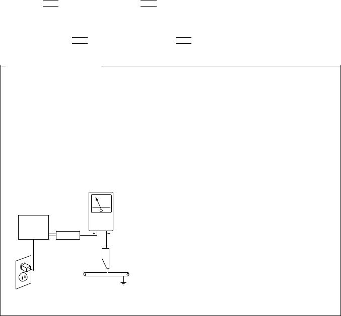
LEAKAGE CURRENT CHECK
Measure leakage current to a known earth ground (water pipe, conduit, etc.) by connecting a leakage current tester such as Simpson Model 229-2 or equivalent between the earth ground and all exposed metal parts of the appliance (input/output terminals, screwheads, metal overlays, control shaft, etc.). Plug the AC line cord of the appliance directly into a 120V AC 60Hz outlet and turn the AC power switch on. Any current measured must not exceed 0.5mA.
|
|
Reading should |
|
Leakage |
not be above |
Device |
current |
0.5mA |
under |
tester |
|
test |
|
|
Test all |
|
|
exposed metal |
|
|
surfaces |
|
|
Also test with |
|
|
plug reversed |
|
Earth |
(Using AC adapter |
|
ground |
plug as required) |
|
|
AC Leakage Test
ANY MEASUREMENTS NOT WITHIN THE LIMITS OUTLINED ABOVE ARE INDICATIVE OF A POTENTIAL SHOCK HAZARD AND MUST BE CORRECTED BEFORE RETURNING THE APPLIANCE TO THE CUSTOMER.
2. PRODUCT SAFETY NOTICE
Many electrical and mechanical parts in the appliance have special safety related characteristics. These are often not evident from visual inspection nor the protection afforded by them necessarily can be obtained by using replacement components rated for voltage, wattage, etc. Replacement parts which have these special safety characteristics are identified in this Service Manual.
Electrical components having such features are identified by marking with a  on the schematics and on the parts list in this Service Manual.
The use of a substitute replacement component which does not have the same safety characteristics as the PIONEER recommended replacement one, shown in the parts list in this Service Manual, may create shock, fire, or other hazards.
Product Safety is continuously under review and new instructions are issued from time to time. For the latest information, always consult the current PIONEER Service Manual. A subscription to, or additional copies of, PIONEER Service Manual may be obtained at a nominal charge from PIONEER.
2
VSA-E03
2. EXPLODED VIEWS AND PARTS LIST
•
•The  mark found on some component parts indicates the importance of the safety factor of the part. Therefore, when replacing, be sure to use parts of identical designation.
•Screws adjacent to  mark on the product are used for disassembly.
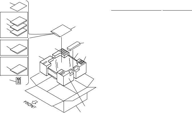
2.1PACKINGNOTES: Parts marked by "NSP" are generally unavailable because they are not in our Master Spare Parts List.
7 |
|
|
(1) PACKING PARTS LIST |
|
||
|
|
|
Mark |
No. |
Description |
Part No. |
HYXJI Type Only |
|
|
|
1 |
Packing Sheet |
AHG7010 |
17 |
|
|
NSP |
2 |
Alkaline Dry Cell Battery |
VEM1012 |
16 |
|
|
|
|
(LR6, AA) |
|
10 |
|
|
3 |
Operating Instructions |
See Contrast table (2) |
|
15 |
|
|
||||
|
|
4 |
• • • • • |
|
||
|
|
|
|
|||
|
Refer to |
|
|
5 |
• • • • • |
|
|
"7.3 REMOTE |
|
6 |
• • • • • |
|
|
Except HVXJI Type |
CONTROL UNIT" |
|
|
|||
|
8 |
NSP |
7 |
Warranty Card |
ARY7022 |
|
14 |
12(1/2) |
|
|
8 |
Remote Control Unit |
AXD7237 |
|
|
|
|
(CU-VSA035) |
|
|
|
|
|
|
|
|
|
11(1/2) |
1 |
12(2/2) |
|
9 |
• • • • • |
|
|
|
10 |
Polyethylene Bag |
Z21-038 |
||
|
|
|
|
|||
Except |
|
|
|
|
(0.03×230×340) |
|
HYXJI/GR Type |
|
|
|
11 |
Front Pad 508 |
AHA7236 |
3 |
|
|
|
|||
|
|
|
|
12 |
Rear Pad 508 |
AHA7237 |
|
|
|
|
13 |
Packing Case E03 |
AHD7781 |
2 |
|
|
|
14 |
Operating Instructions |
See Contrast table (2) |
|
|
|
15 |
Operating Instructions |
See Contrast table (2) |
|
|
|
|
|
16 |
Operating Instructions |
See Contrast table (2) |
|
|
|
|
17 |
Operating Instructions |
See Contrast table (2) |
|
|
11(2/2) |
|
|
|
|
|
13 |
|
|
|
|
|
(2) CONTRAST TABLE
VSA-E03/HYXJI, HYXJI/GR and HVXJI are constructed the same except for the following :
Mark |
No. |
Symbol and Description |
|
Part No. |
|
Remarks |
|
HYXJI Type |
HYXJI/GR Type |
HVXJI Type |
|||||
|
|
|
|
||||
|
3 |
Operating Instructions (English) |
ARB7212 |
Not used |
ARB7212 |
|
|
|
14 |
Operating Instructions (German) |
ARC7226 |
ARC7226 |
Not used |
|
|
|
15 |
Operating Instructions (French/Italian) |
ARC7267 |
Not used |
Not used |
|
|
|
16 |
Operating Instructions (Swedish/Dutch) |
ARC7268 |
Not used |
Not used |
|
|
|
17 |
Operating Instructions (Portuguese/Spanish) |
ARC7269 |
Not used |
Not used |
|
|
|
|
|
|
|
|
|
3
VSA-E03
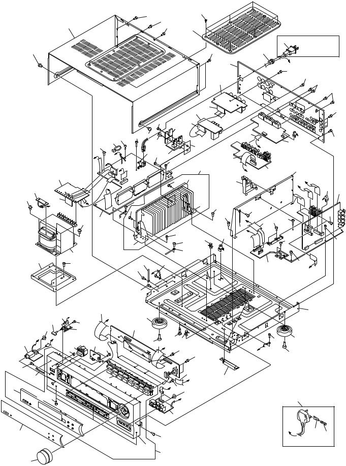
2.2 EXTERIOR
74
|
57 |
57 |
|
32 |
|
|
|
|
57 |
|
|
|
|
75 |
|
|
|
|
26 Except HVXJI Type |
60 |
|
57 |
28 |
Note 1 : +2
Torque is 12 –0 kg • cm
|
8 |
|
|
7 |
|
55 |
10 |
J |
|
K |
|
|
|
|
|
|
55 |
33 |
18 |
|
57 |
||
|
|
59 |
N |
|
45 |
59 |
|
53 |
15 |
E |
L |
|
6 |
|
|
|
44 |
|
|
|
|
|
|
50 |
57
49
42
 57
57
46
41
31 |
P (HVXJI Type Only) |
72
57
16
|
|
|
|
|
|
|
|
11 |
|
|
|
|
|
|
1 |
|
|
4 |
|
|
|
|
|
|
|
|
|
|
|
|
|
|
|
57 |
69 |
12 |
|
|
|
|
|
|
|
|
|
|
|
|
|
|
61 57 |
58 60 |
|
|
|
|
|
|
|
|
|
|
53 |
|
|
|
|
|
|
57 |
|
|
1 |
|
|
|
68 |
|
|
L |
K |
|
19 54 66 |
|
|
|
24 |
||
|
N |
|
|
|
57 |
|
|
||
|
|
|
|
|
|
|
|||
|
D |
|
|
|
|
|
|
35 |
|
|
|
|
|
|
|
|
|
|
|
|
|
|
|
|
|
65 |
64 |
|
29 |
|
I |
|
|
|
|
|
|
||
|
|
|
|
|
|
|
|
|
|
|
|
57 |
|
|
|
|
|
63 |
57 |
|
|
65 |
|
|
|
|
|
||
|
|
|
|
|
|
|
|
||
5 |
|
|
|
|
|
|
|
|
57 |
|
|
|
|
|
|
|
|
|
|
|
|
|
|
|
|
57 |
57 |
39 |
38 |
|
|
|
|
|
|
|
|
||
|
|
62 |
|
|
|
|
|
|
|
|
|
|
|
|
|
79 |
|
|
|
|
|
|
|
|
|
|
|
|
|
|
|
40 |
|
|
57 |
|
|
|
|
|
|
57 |
E |
|
|
|
|
|
|
|
|
57 |
|
|
|
|
|
|
|
21 |
36 |
|
|
|
|
|
|
|
|
|
D |
|
|
|
|
|
|
|
|
|
|
|
|
|
|
|
|
|
|
|
|
2 |
|
|
|
|
|
|
|
3 |
|
|
57 |
25 |
37 |
39 |
|
|
|
59 |
|
C |
59 |
|
|
||||
|
|
|
|
|
|
||||
|
|
|
|
|
|
|
|
59 |
|
|
|
|
|
|
|
|
22 |
|
|
|
43 |
|
|
|
|
|
B Accessories of |
||
|
|
|
|
|
H 59 53 |
Front Panel |
|||
|
|
|
|
|
(No. 47) |
|
|||
|
|
|
|
|
|
A |
|
|
|
|
|
|
|
|
9 |
|
|
|
|
|
|
|
|
|
57 |
|
|
|
|
|
|
47 |
|
78 |
|
|
|
|
|
|
|
|
|
|
|
|
|
|
|
|
|
|
|
57 |
|
|
|
|
|
57 |
|
|
|
|
|
|
57 |
73 |
|
|
H |
|
57 |
|
|
|
|
||
|
M |
|
14 |
|
|
|
|
|
|
|
|
F |
13 |
34 |
|
|
|
|
|
|
F |
|
|
|
|
|
M |
27 |
|
|
|
|
|
17 |
|
|
|
|
|
|
|
|
|
|
C |
H |
|
57 |
|
|
|
|
|
|
|
|
57 |
|
|
J |
|
|
58 |
|
|
76 |
57 |
|
|
||
40 |
|
|
|
|
|
|
|
|
|
|
|
I |
|
|
|
|
|
|
|
|
57 |
|
57 |
|
1 |
|
57 |
|
|
|
|
B |
|
|
|
|
|
|
|
|
|
30
57 36
A 57
26
P |
70 |
71 |
|
||
|
|
|
HVXJI Type Only |
||
4
VSA-E03
(1) EXTERIOR PARTS LIST
Mark |
No. |
Description |
|
Part No. |
Mark |
No. |
Description |
|
Part No. |
|
1 |
INPUT Assy |
|
AWX7438 |
|
41 |
Volume Knob 508 |
|
AAB7179 |
|
2 |
FRONT Assy |
|
AWX7439 |
|
42 |
Sub Panel 508 |
|
AAD7482 |
NSP |
3 |
POWER SW Assy |
|
AWX7222 |
|
43 |
Function Button E03 |
|
AAD7543 |
|
4 |
REAR SP Assy |
|
AWX7251 |
|
44 |
Power Button |
|
AAD7440 |
|
5 |
AMP Assy |
|
AWX7446 |
|
45 |
Power Button M |
|
AAD7442 |
NSP |
6 |
HEADPHONE Assy |
|
AWX7230 |
|
|
|
|
|
|
7 |
TRANS 1 Assy |
|
AWX7287 |
|
46 |
Display Window W5 |
|
AAK7594 |
|
8 |
TRANS 2 Assy |
|
AWX7292 |
|
47 |
Front Panel E03 |
|
AMB7647 |
NSP |
9 |
FRONT VIDEO Assy |
|
AWX7241 |
|
48 |
• • • • • |
|
|
|
10 |
BARRIER Assy |
|
AWX7284 |
|
49 |
Name Plate |
|
PAM1776 |
NSP |
11 |
F.SP.CONNECT Assy |
|
AWX7285 |
|
50 |
LED Lens |
|
PNW2019 |
|
|
|
|
|
|
||||
NSP |
12 |
R.C.SP.CONNECT Assy |
|
AWX7286 |
|
51 |
• • • • • |
|
|
|
13 |
VIDEO Assy |
|
AWX7441 |
|
52 |
• • • • • |
|
|
|
14 |
SVIDEO Assy |
|
AWX7450 |
|
53 |
Screw |
|
ABA7009 |
|
15 |
MECH SW Assy |
|
AWX7247 |
|
54 |
Screw |
|
ABA7043 |
|
16 |
FRONT LARGE Assy |
|
AWX7245 |
|
55 |
Screw |
|
ABA7044 |
|
|
|
|
|
|
|
|||
|
17 |
DOLBY DIGITAL Assy |
|
AWX7196 |
|
56 |
• • • • • |
|
|
|
18 |
Power Transformer (T1) |
|
ATS7242 |
|
57 |
Screw |
|
BBZ30P080FZK |
|
19 |
Fuse (FU1 : T2.5A) |
|
REK-104 |
|
58 |
Screw |
|
BBZ30P200FMC |
|
20 |
• • • • • |
|
|
|
59 |
Screw |
|
BPZ30P080FMC |
|
21 |
FFC 21P (J2) |
|
ADD7100 |
|
60 |
Screw |
|
FBT40P080FZK |
|
|
|
|
|
|
|
|||
|
22 |
FFC 15P (J4) |
|
ADD7102 |
NSP |
61 |
Binder (BK-1) |
|
ZCA-BK1 |
|
23 |
• • • • • |
|
|
|
62 |
Heat Sink Angle F |
|
ANG7194 |
|
24 |
FFC 17P (J8) |
|
ADD7107 |
|
63 |
Heat Sink Angle R |
|
ANG7195 |
|
25 |
FFC 26P (J3) |
|
ADD7118 |
NSP |
64 |
Heat Sink D5 |
|
ANH7090 |
|
26 |
AC Power Cord |
|
See Contrast table (2) |
|
65 |
Screw |
|
BBZ30P080FMC |
|
|
|
|
|
|
|
|||
NSP |
27 |
8P Shield Cable (J6) |
|
ADX7243 |
NSP |
66 |
FET Assy |
|
AWX7228 |
|
28 |
Cord Stopper |
|
CM-22B |
|
67 |
• • • • • |
|
|
|
29 |
Tuner Holder B |
|
AAD7490 |
|
68 |
Sheet |
|
AEE7026 |
NSP |
30 |
Under Base D5 |
|
ANA7079 |
|
69 |
FET Angle |
|
ANG7186 |
|
31 |
Rear Panel |
|
ANC7859 |
|
70 |
Fuse Holder |
|
See Contrast table (2) |
|
|
|
|
|
|
|
|||
|
32 |
Bonnet Case |
|
AZN7771 |
|
71 |
Fuse (T5A) |
|
See Contrast table (2) |
|
33 |
Trans Frame |
|
ANG7193 |
|
72 |
Screw |
|
ABA1007 |
|
34 |
DSP Shield |
|
ANG7196 |
|
73 |
FFC 11P (J7) |
|
ADD7142 |
NSP |
35 |
Heat Sink Assy D5 |
|
ANH7095 |
|
74 |
Push Rivet |
|
AEC7025 |
|
36 |
Insulator |
|
PNW2766 |
|
75 |
Top Cover |
|
AME7375 |
|
|
|
|
|
|
|
|||
|
37 |
Locking Card Spacer |
|
AEC7160 |
NSP |
76 |
Shrink Shield 140 |
|
PDM1021 |
|
38 |
PCB Mold |
|
AMR2533 |
|
77 |
• • • • • |
|
|
NSP |
39 |
Card Spacer |
|
DEC1770 |
|
78 |
Front Panel E03 Assy |
|
AMB7648 |
NSP |
40 |
Binder |
|
RNE1277 |
|
79 |
Cord Clamper |
|
RNH-184 |
(2) CONTRAST TABLE
VSA-E03/HYXJI, HYXJI/GR and HVXJI are constructed the same except for the following :
Mark |
No. |
Symbol and Description |
|
Part No. |
|
Remarks |
|
HYXJI Type |
HYXJI/GR Type |
HVXJI Type |
|||||
|
|
|
|
||||
|
26 |
AC Power Cord |
VDG1061 |
VDG1061 |
VDG1063 |
|
|
|
70 |
Fuse Holder |
Not used |
Not used |
VKR1003 |
|
|
|
71 |
Fuse (T5A) |
Not used |
Not used |
PEK1003 |
|
|
|
|
|
|
|
|
|
5
A
B
1  2
2  3
3  4
4
VSA-E03
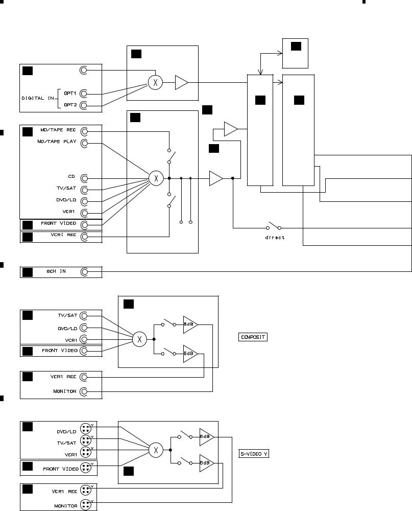
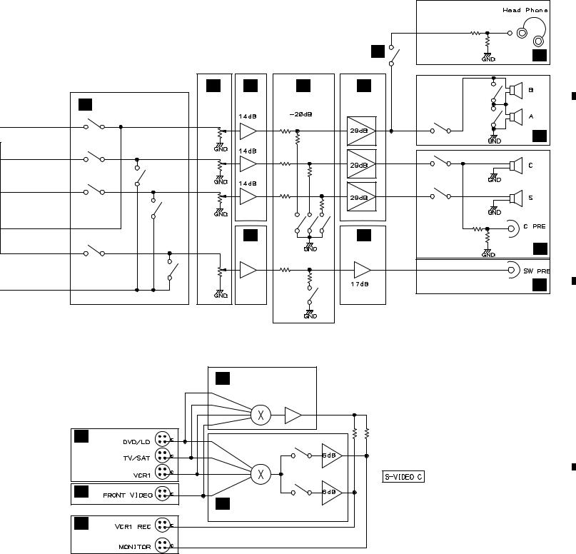
3. BLOCK DIAGRAM AND SCHEMATIC DIAGRAM
3.1 BLOCK DIAGRAM |
Q |
|
|
|
|
|
|
Q |
|
|
|
DIGITAL INPUT |
|
|
|
|
|
DSP |
|
|
|
|
IC9151 |
|
|
|
|
|
IC9321 |
Q |
|
5 |
TC74ACT151AF |
|
|
|
|
|
MB86342B |
OPT OUT |
|
|
|
|
|
|
|
||
|
|
|
|
|
|
|
|
||
|
|
|
|
5 |
|
|
42 |
|
|
|
|
2 |
|
|
|
|
|
|
|
|
|
1 |
|
|
|
|
|
|
|
|
|
|
|
|
|
ANALOG INPUT |
Q |
Q |
|
|
|
|
|
|
Q |
CODEC IC |
GAIN CHANGE |
||
|
|
A |
FUNC. SELECTOR |
IC9201 |
|
IC9401 |
& |
||
|
|
|
NJM2100M |
CS4226-KQ |
MIXING |
||||
|
|
|
IC101 |
|
|
|
|
|
IC9601 |
A |
|
29 |
TC9274N |
|
|
3 |
1 14 |
|
TC9164AF |
|
|
|
|
|
|
|
|
||
|
|
|
|
|
|
|
|
|
|
|
|
|
|
|
A |
|
|
5 |
|
|
|
|
|
|
BUFFER |
|
|
||
|
|
34 |
|
|
|
|
|
||
|
|
|
|
|
IC109 |
|
|
8 |
|
|
|
|
|
|
UPC4570G2 |
|
|
||
|
|
|
|
|
|
|
|
||
|
|
35 |
|
|
5 |
7 |
|
|
|
|
|
36 |
|
|
|
|
|
|
|
|
|
37 |
|
|
|
|
|
|
18 |
|
|
40 |
|
|
|
|
|
|
|
|
|
41 |
|
|
|
|
|
|
|
P |
|
|
TAPE2OUT |
TAPE2IN |
|
|
|
|
|
A |
|
31 |
|
|
|
|
|
||
|
|
|
|
|
|
|
|
|
|
N
|
N |
FUNC. SELECTOR |
|
|
|
N |
|
IC501 |
|
NJM2296D |
|
|
|
5
C 7
9
3
P
11 1
N
D
O |
7 |
|
|
|
|
|
|
|
5 |
|
1 |
|
|
|
|
|
9 |
|
|
P |
3 |
|
11 |
|
|
||
|
O |
S-Y FUNC. SELECTOR |
|
|
|
||
|
|
|
|
|
|
|
IC551 |
|
|
|
NJM2296D |
O
6
|
1 |
|
2 |
|
3 |
|
4 |
|
|
|
|
|
|
||||
|
|
|
|
|
|
5 |
|
6 |
|
7 |
|
8 |
|
|
|
|
|
|
VSA-E03
Note : When ordering service parts, be sure to refer to "EXPLODED VIEWS and PARTS LIST" or "PCB PARTS LIST".
A |
DSP/6ch IN SELECTOR |
IC102, IC103 |
|
|
LC4966 |
O
P
O
A A A
ELECTRIC |
14dB PRE |
20dB ATT |
||||
VOLUME |
UPC4570G2 |
|
|
|
||
LC7536M |
|
|
|
|
|
|
29 |
23 |
5 |
7 |
|
|
|
|
|
|
|
|||
|
|
|
|
|
||
IC303 |
|
|
IC306 |
|
|
|
2 |
8 |
3 |
1 |
|
|
|
|
|
|
|
|||
|
|
|
|
|
||
IC301 |
|
|
IC304 |
|
|
|
29 |
23 |
5 |
7 |
|
|
|
|
|
|
|
|||
|
|
Q408 |
Q1453 |
Q458 |
||
IC302 |
|
|
IC305 |
|||
|
|
|
|
|
||
|
|
A |
|
29 |
|
BUFFER |
|
UPC4570G2 |
|||
|
|||
23 |
5 |
7 |
|
|
|||
IC301 |
|
IC304 |
|
|
|
Q1351 |
|
|
O |
S-DC FUNC. SELECTOR |
|
|
|
15 |
|
IC553 |
|
TC4051BP |
|
14 |
|
|
13 |
|
3 |
15 |
|
|
A
D |
I |
|
RY401 |
||
|
A
RY628
POWER
AMPLIFIER
RY626 RY627
1 |
12 |
IC401 |
G |
|
|
PAC007A |
|
RY651
113
IC403
PAC008A
RY652 |
B |
312
IC402
PAC007A
|
A |
|
17dB PRE |
H |
|
UPC4570G2 |
||
3 |
1 |
|
D
C
7 |
|
|
5 |
|
1 |
|
|
|
9 |
|
|
3 |
|
11 |
|
|
|
|
O |
S-C FUNC. SELECTOR |
|
IC552 |
|
|
|
|
|
|
NJM2296D |
D
7
|
5 |
|
6 |
|
7 |
|
8 |
|
|
|
|
|
|
||||
|
|
|
|
|
|
1 |
|
2 |
|
3 |
|
4 |
|
|
|
|
|
|
VSA-E03
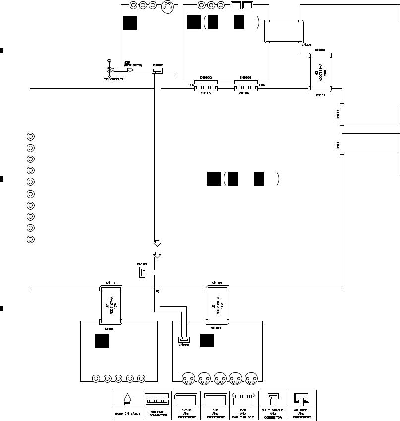
3.2 OVERALL WIRING CONNECTION DIAGRAM
A
P |
Q Q 1/3- Q 3/3 |
J4 |
|
FRONT VIDEO |
|
|
|
DOLBY DIGITAL |
|
15P |
|
ASSY |
|
|
|
ASSY |
CN9371 |
|
|
(AWX7241) |
|
|
|
(AWX7196) |
|
|
|
|
|
|
|
B
A A 1/2, A 2/2
INPUT ASSY (AWX7438)
C
N |
O |
VIDEO ASSY |
SVIDEO ASSY |
(AWX7441) |
(AWX7450) |
D
8
|
1 |
|
2 |
|
3 |
|
4 |
|
|
|
|
|
|
||||
|
|
|
|
|
|
5 |
|
6 |
|
7 |
|
8 |
|
|
|
|
|
|
VSA-E03
A
|
C POWER SW |
I |
MB |
|
|
HEADPHONE |
|||
B |
MECH SW |
|||
ASSY |
ASSY |
ASSY |
||
FRONT ASSY |
(AWX7222) |
(AWX7230) |
||
(AWX7247) |
||||
|
|
|||
(AWX7439) |
|
|
||
|
|
|
K TRANS 1 ASSY (AWX7287)
POWER TRANSFORMER (T1) |
|
(ATS7242) |
B |
|
J |
TRANS 2 ASSY |
|
(AWX7292) |
|
L |
BARRIER ASSY |
|
(AWX7284) |
|
MA |
|
FET ASSY |
D D 1/2, |
D 2/2 |
C |
(AWX7228) |
|||
|
|
|
AMP ASSY
(AWX7446) J52 J51
FU1 REK-104 (T2.5A)
F |
E |
|
R.C.SP. |
F.SP. |
|
CONNECT ASSY |
CONNECT ASSY |
AC220-230V |
(AWX7286) |
(AWX7285) |
AC POWER CORD |
|
|
|
|
|
HYXJI and HYXJIGR |
|
|
TYPES : VDG1061 |
|
|
HVXJI TYPES : VDG1063 |
|
|
D |
H |
|
G |
|
REAR SP ASSY |
FRONT LARGE ASSY |
||
(AWX7251) |
(AWX7245) |
||
9
|
5 |
|
6 |
|
7 |
|
8 |
|
|
|
|
|
|
||||
|
|
|
|
|
|
1 |
|
2 |
|
3 |
|
4 |
|
|
|
|
|
|
VSA-E03
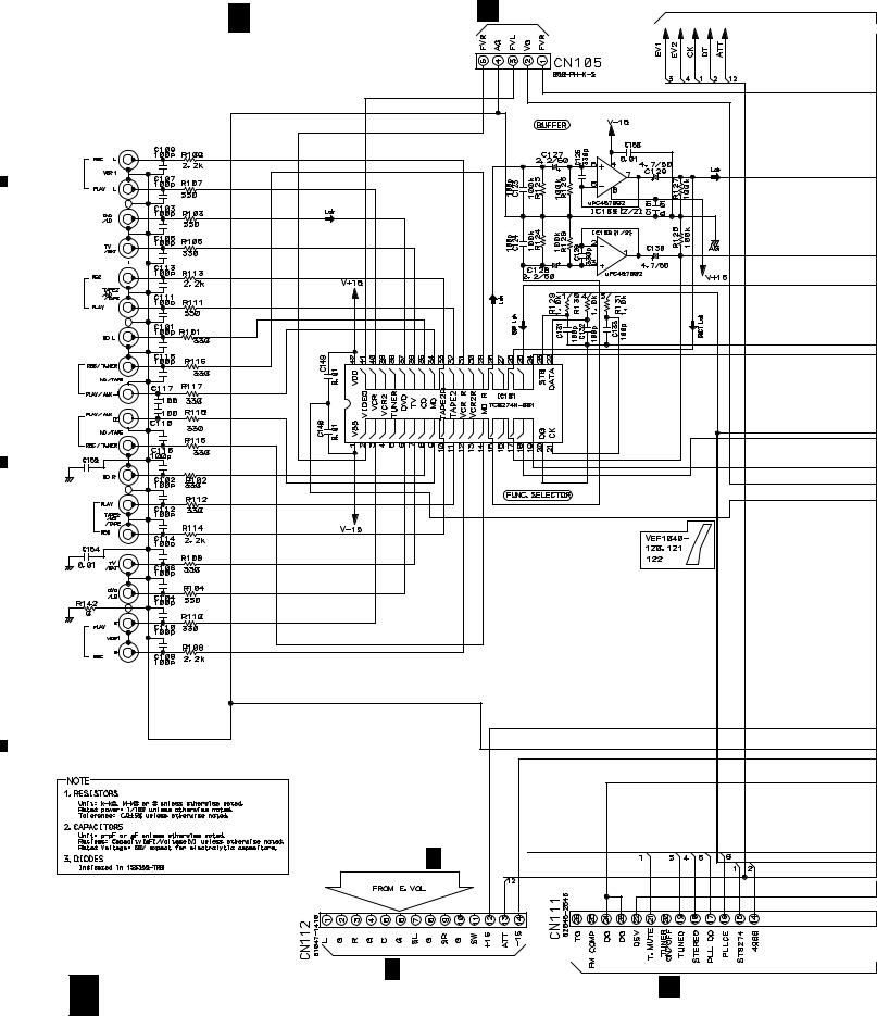
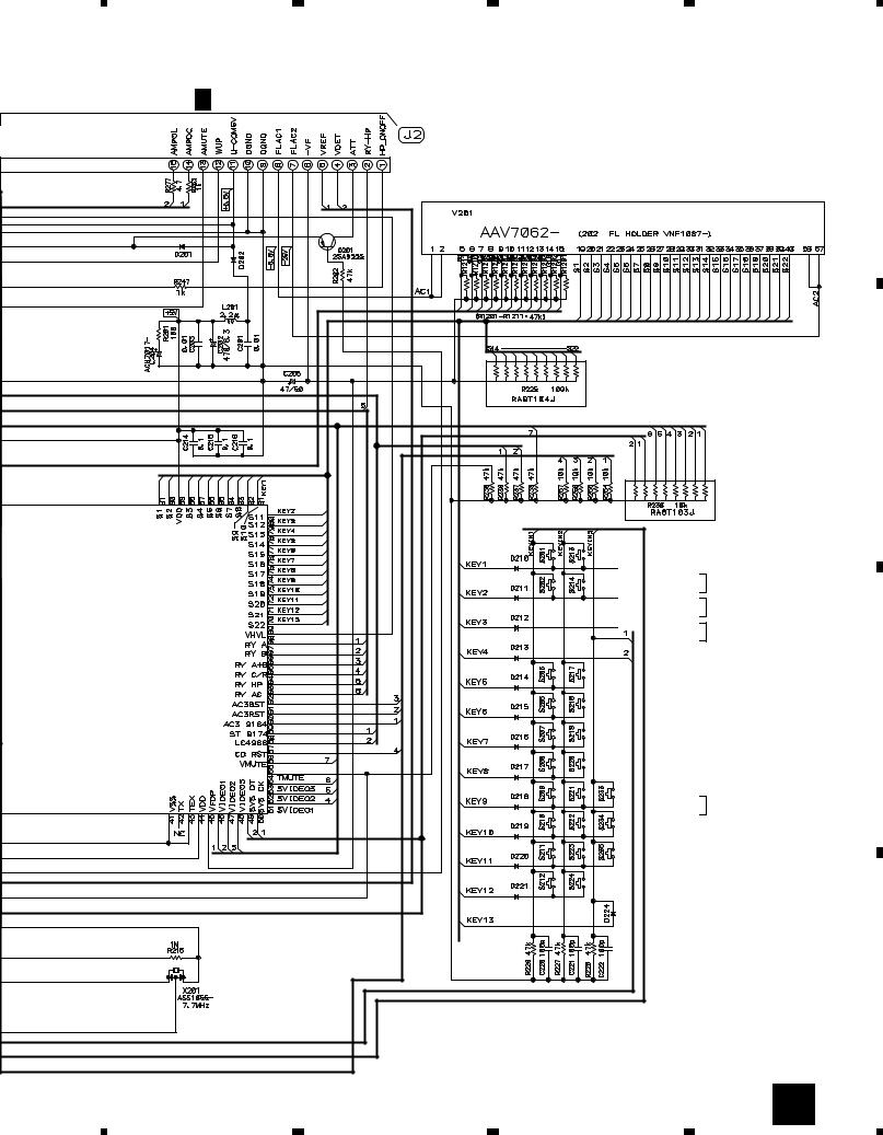
3.3 INPUT ASSY (1/2)
A 1/2
A
•
INPUT ASSY(1/2) |
P CN602 |
|
|
(AWX7438) |
|
FUNCTION BLOCK |
|
JA103 (1/2) |
AKB7012 |
|
JA102 (1/2) |
AKB7012 |
|
B |
|
|
JA101 (1/2) |
AKB7012 |
|
JA101 (2/2) |
AKB7012 |
|
|
0.01 |
|
JA102 (2/2) |
AKB7012 |
|
C |
|
|
JA103 (2/2) |
AKB7012 |
|
|
|
A 2/2 |
D |
|
|
10 |
D 1/2 |
406 |
A 1/2 |
B CN202 |
|
|
|
|
1 |
|
2 |
|
3 |
|
4 |
|
|
|
|
|
|
||||
|
|
|
|
|
|
5 |
|
6 |
|
7 |
|
8 |
|
|
|
|
|
|
VSA-E03
A 2/2
|
|
|
|
|
|
|
|
|
|
|
|
|
|
|
L ch |
: AUDIO SIGNAL ROUTE |
|
|
|
|
|
|
|
|
|
|
|
|
|
|
|
|
|
|
|
|
|
|
|
|
|
|
|
|
|
|
|
|
C ch |
A |
|
|
|
|
|
|
|
|
|
|
|
|
|
|
|
|
: AUDIO SIGNAL ROUTE (CENTER) |
|
FL ch |
|
: AUDIO SIGNAL ROUTE (FRONT) |
|
Q 1/3 |
|
CN9801 |
|
B |
|
O |
|
CN554 |
|
J 352 |
ACH7112 |
|
|
3300/35 |
ACH7113 |
|
2200/35 |
|
|
C |
ACH7111 |
3300/16 |
|
N |
|
CN507 |
|
Q 1/3 |
|
CN9802 |
|
D |
: The power supply is shown with the marked box.
A 1/2 11
|
5 |
|
6 |
|
7 |
|
8 |
|
|
|
|
|
|
||||
|
|
|
|
|
|
1 |
|
2 |
|
3 |
|
4 |
|
|
|
|
|
|
VSA-E03
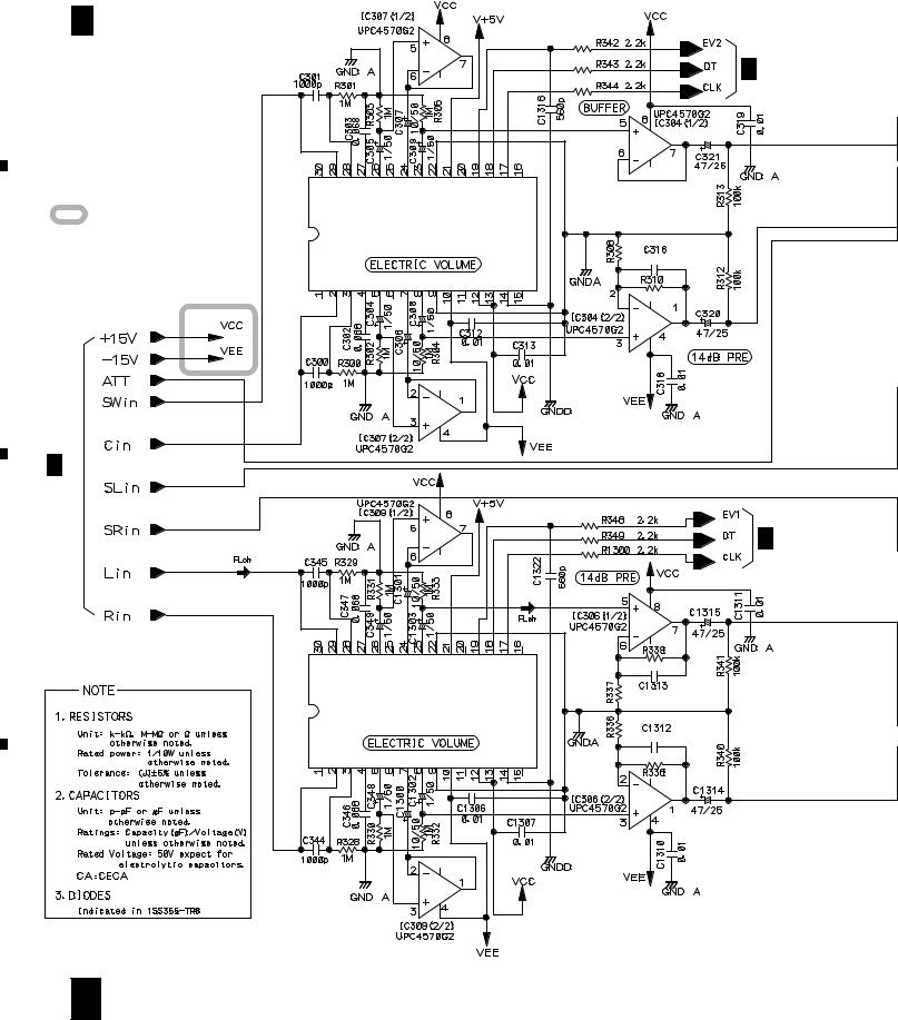
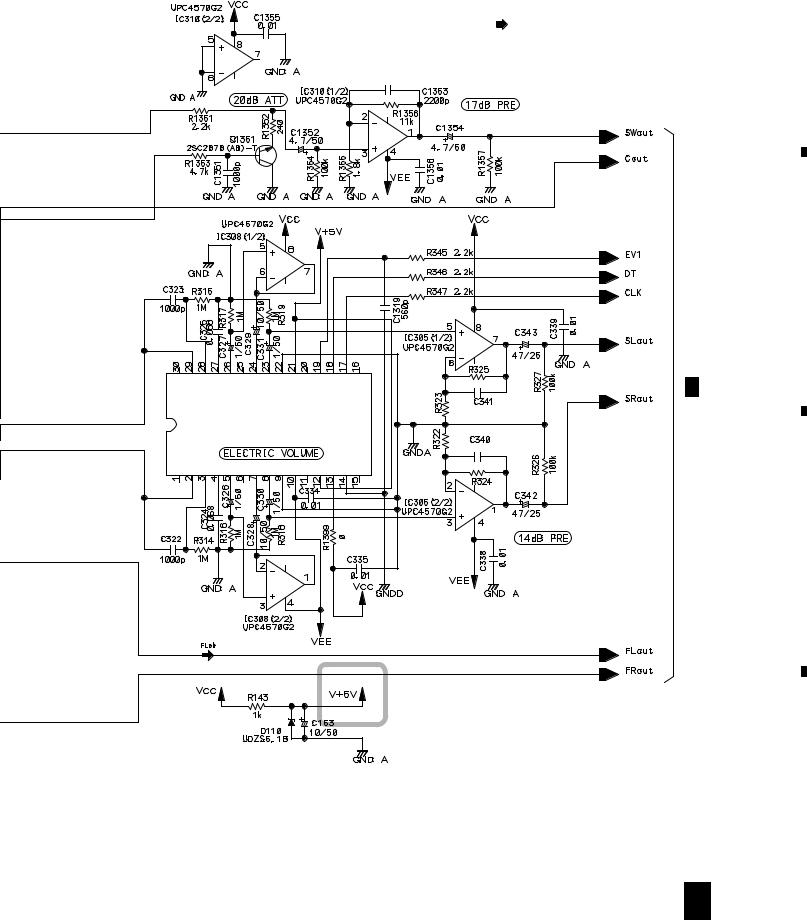
3.4 INPUT ASSY (2/2)
A |
A 2/2 INPUT ASSY(2/2) |
|
|
|
|
|
(AWX7438) |
|
|
• E. VOL BLOCK |
A 1/2 |
:The power supply is shown with the marked box.
B
A 1/2
IC301 |
|
LC7535M |
|
(LC7536M) |
|
3k |
120p |
|
|
|
12k |
A 1/2
C |
|
|
|
|
12k |
IC303 |
3k |
68p |
LC7535M |
|
|
(LC7536M) |
|
|
|
3k |
68p |
|
|
|
|
|
12k |
D
12 A 2/2
|
1 |
|
2 |
|
3 |
|
4 |
|
|
|
|
|
|
||||
|
|
|
|
|
|
5 |
|
6 |
|
7 |
|
8 |
|
|
|
|
|
|
VSA-E03
FL ch |
A |
: AUDIO SIGNAL ROUTE (FRONT) |
|
|
|
B |
|
|
12k |
A 1/2 |
|
|
|
|
IC302 |
3k |
120p |
|
|
|
|
|
LC7535M |
|
|
|
(LC7536M) |
3k |
|
|
|
120p |
|
|
|
|
|
|
|
|
12k |
|
|
|
|
C |
D
A 2/2 13
|
5 |
|
6 |
|
7 |
|
8 |
|
|
|
|
|
|
||||
|
|
|
|
|
|
1 |
|
2 |
|
3 |
|
4 |
|
|
|
|
|
|
VSA-E03
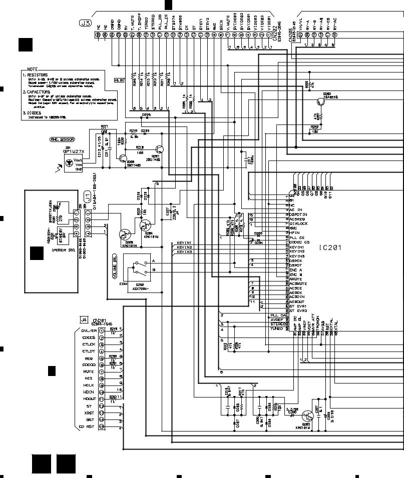
3.5 FRONT and POWER SW ASSYS
A 1/2 CN111
A
B FRONT ASSY (AWX7439)
B |
|
|
|
|
|
C |
MASTER VOLUME |
|
PDG254A |
|
|
|
||
|
POWER SW |
|
|
|
|
ASSY |
|
|
|
C |
(AWX7222) |
|
|
|
|
Q 2/3 |
|
|
|
|
CN9371 |
|
|
|
D |
|
|
|
|
14 |
B C |
|
|
|
|
1 |
2 |
3 |
4 |
5 |
6 |
7 |
D 2/2 |
CN401 |
|
5 |
6 |
7 |
8
VSA-E03
FRONT ASSY
S201 : MIDNIGHT
S202 : DSP MODE
S205 : –
S206 : + BASS
S207 : –
TREBLE
S208 : +
S209 : A
SPEAKERS
S210 : B
S211 : LOUDNESS
S212 : DIRECT
S213 :  (DOLBY)
S214 : SIGNAL SELECT
S217 : TV/SAT
S218 : VIDEO
S219 : CD
S220 : TUNER
S221 : VCR
S222 : DVD/LD
S223 : MD/TAPE
S224 : AUX
S233 : –
CHANNEL LEVEL
S234 : +
S235 : CHANNEL SELECT
S250 : MASTER VOLUME
B 15
8
A
B
C
D

|
1 |
|
2 |
|
3 |
|
4 |
|
|
|
|
|
|
VSA-E03
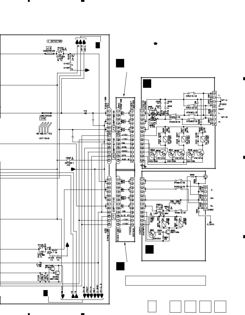
3.6AMP (1/2), F.SP.CONNECT, R.C.SP.CONNECT, FRONT LARGE and REAR SP ASSYS
A
B
A 1/2 CN112
C
D
16
D 2/2 


D 1/2
4.7/50 NP
10/50
10/50
4.7/50 NP
C1439 |
|
YF |
|
10000p |
|
R1456 |
|
4.7 |
|
4.7/50 |
C1442 |
SL |
|
NP |
220p |
|
/500 |
39p 39p
4.7/50
NP
 10/50
10/50
10/50
NP
4.7/50
C1438 |
|
330p |
D 1/2 AMP ASSY(1/2) |
|
|
JA413 |
(AWX7446) |
AKB7111 |
|
C439 SL
220p
/500
C1441 SL
220p
/500
C442 SL
220p 
/500
D 2/2 
|
1 |
|
2 |
|
3 |
|
4 |
|
|
|
|
|
|
||||
|
|
|
|
|
|
5 |
|
6 |
|
|
|
D 2/2 |
|
0.22 |
RETURN |
|
|
0.22 |
||
|
|
|
|
|
|
C443 |
SL |
|
|
220p/500 |
|
|
C444 |
SL |
|
|
220p/500 |
|
|
|
RETURN |
|
|
|
RETURN |
|
|
0.22 |
0.22 |
|
|
D 2/2 |
|
|
|
|
5 |
|
6 |
|
7 |
|
8 |
|
|
|
|
VSA-E03
FL ch
A
: AUDIO SIGNAL ROUTE (FRONT)
E F.SP. CONNECT ASSY |
|
|
|
|
(AWX7285) |
|
|
|
|
G FRONT LARGE ASSY |
|
|
||
(AWX7245) |
|
|
|
|
|
0.22 |
0.01 |
0.01 |
|
0.22 |
0.01 |
|
||
0.22 |
|
|
|
|
|
0.22 |
|
0.01 |
|
|
|
|
AKE7026 |
|
|
|
|
|
|
|
|
0.01 |
0.01 |
B |
|
|
|
||
|
|
|
JA653 |
|
|
|
20k |
AKB7111 |
|
|
|
|
|
|
|
|
2k |
|
|
|
|
0.01 |
|
|
|
|
0.01 |
|
C |
|
|
|
|
|
|
0.22 0.22 |
0.01 |
|
|
|
|
|
|
|
|
|
0.01 |
AKE7042 |
|
|
|
|
|
|
H REAR SP ASSY (AWX7251)
F R.C.SP. CONNECT ASSY
(AWX7286)
D
CAUTION : FOR CONTINUED PROTECTION AGAINST RISK OF FIRE, REPLACE ONLY WITH SAME TYPE NO. ICP-N25, MFD BY ROHM CO., LTD. FOR IC404 and IC405.
|
|
D |
1/2 |
E |
|
F |
|
G |
|
H |
17 |
|
||
|
|
|
7 |
|
|
|
|
|
|
|
|
8 |
|
|
|
|
|
||||||||||||
|
|
|
||||||||||||
|
1 |
|
2 |
|
3 |
|
4 |
|
|
|
|
|
|
VSA-E03
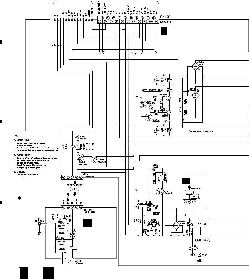
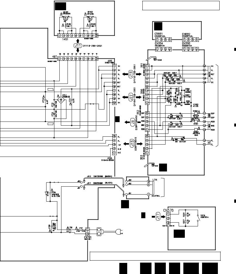
3.7AMP (2/2), HEADPHONE, TRANS 2, TRANS 1, BARRIER, FET and MECH SW ASSYS
D |
1/2 |
B |
CN203 |
A
D 2/2
AMP ASSY(2/2) (AWX7226)
(B)
B
+42.4 (B)
–42.4
C
HP
: AUDIO SIGNAL ROUTE (HEAD PHONE)
D
I
HEADPHONE ASSY (AWX7230)
MB CN376
ATT7037 1000/25 


VNF-091
18 D 2/2 I
|
1 |
|
2 |
|
3 |
|
4 |
|
|
|
|
|
|
||||
|
|
|
|
|
|
5 |
|
6 |
|
7 |
|
8 |
|
|
|
|
|
|
VSA-E03
CAUTION : FOR CONTINUED PROTECTION AGAINST RISK OF FIRE,
MA FET ASSY (AWX7228) REPLACE ONLY WITH SAME TYPE NO. ICP-N70, MFD BY ROHM CO., LTD. FOR IC353.
CAUTION : FOR CONTINUED PROTECTION AGAINST RISK OF FIRE, |
A |
|
|
REPLACE ONLY WITH SAME TYPE NO. 491005, MFD BY |
|
LITTELFUSE INK. FOR IC351, IC352 (AEK7019). |
|
L BARRIER ASSY (AWX7284)
+59.5 |
|
B |
|
TRANS.MAIN |
|
|
A 1/2 |
|
|
(B) |
|
|
|
1.8k |
|
|
NP |
–59.5 |
CN115 |
|
|
|
AC240V
AC230V
C
J TRANS 2 ASSY (AWX7292)
MAIN TRANS.
REK-104
T2.5A250V
ATF-151
K TRANS 1 ASSY |
|
|
(AWX7287) |
|
|
D 2/2 |
|
|
410 |
|
|
LIVE |
|
|
AC220-230V |
MB |
|
NEUTRAL AC POWER CORD |
||
MECH SW ASSY |
||
VDG1061: EXCEPT HVXJI TYPE |
||
VDG1063: HVXJI TYPE ONLY |
(AWX7247) |
|
• NOTE FOR FUSE REPLACEMENT |
||
|
D
CAUTION -FOR CONTINUED PROTECTION AGAINST RISK OF FIRE. REPLACE WITH SAME TYPE AND RATINGS ONLY.
D 2/2 J 
 K
K 
 L
L 
 MA
MA 
 MB 19
MB 19
|
5 |
|
6 |
|
7 |
|
8 |
|
|
|
|
|
|
||||
|
|
|
|
|
 Loading...