


AUDIO/VIDEO MULTI-CHANNEL AMPLIFIER
VSA-AX10
Operating Instructions

Thank you for buying this Pioneer product.
Please read through these operating instructions so you will know how to operate your model properly. After you have finished reading the instructions, put them away in a safe place for future reference.
Installing the Amplifier
VENTILATION: When installing this unit, make
sure to leave space around the unit for ventilation to improve heat radiation (at least 60 cm at top, 10 cm at rear and front, and 30 cm at each side). WARNING: Slot and openings in the cabinet are
provided for ventilation and to ensure reliable operation of the product and to protect it from overheating, to prevent fire hazard, the openings should never be blocked and covered with items, such as newspapers, tablecloths, curtains, etc. Also do not put the apparatus on the thick carpet, bed, sofa, or fabric having a thick pile.
This product is for general household purposes. Any failure due to use for other than household purposes (such as long-term use for business purposes in a restaurant or use in a car or ship) and which requires repair will be charged for even during the warranty
2 period.
Operating Environment H045 En
Operating environment temperature and humidity: +5°C – +35°C (+41°F – +95°F); less than 85%RH (cooling vents not blocked)
Do not install in the following locations
•Location exposed to direct sunlight or strong artificial light
•Location exposed to high humidity, or poorly ventilated location
En

Features
Advanced Multichannel Stereophonic Concept
The VSA-AX10 amplifier is constructed with Pioneer’s industry-leading advanced multichannel stereophonic concept. This means it is designed to reproduce music and movie soundtracks as close as possible to the intentions of the producer during mastering. The amplifier uses a revolutionary 3-D Frame Construction technique and a Symmetrical Power Train Design, with high-performance Advanced Direct Energy MOS-FET output devices, generating 170 watts (DIN 6 Ω ) of power for 7 independent channels. True 32-bit Tri Digital
Signal Processing is used for ultra realistic sound.
Multi-Channel Acoustic Calibration System (MCACC)
In order to make setting up as easy as possible for users we have created the MCACC system. This unique and convenient way of getting good surround sound from the amplifier makes trouble-free setup a snap. With the included microphone plugged into the front panel the MCACC system creates a monitoring environment to establish the parameters of the sound for the specific room you are using. The MCACC system adjusts the parameters to establish excellent surround sound effects and offers you studio quality home theater sound with minimum effort.
Universal Player Compatibility (DVD Audio)
This amplifier features eight discrete channels of analog inputs, each with 96kHz/24bit A/D converters. This makes it ideal for use with all audio formats, including DVD-Audio, and allows very high quality digital processing. Furthermore, using the MCACC system you can setup this amplifier for optimal DVD-Audio playback.
Next Generation THX Standards and New Digital Formats
The VSA-AX10 is the first amplifier in the world to be THX Ultra2 certified. Among the new THX technologies is
ASA (Advanced Speaker Array), which can process any 5.1 channel source for 7.1 channel playback (THX Ultra2 Cinema and THX MusicMode), or 6.1 channel playback (THX Surround EX). THX Surround EX technology makes possible true playback of Dolby Digital Surround EX soundtracks. The VSA-AX10 is also among the first generation of products able to play discs that feature high quality DTS 96/24 soundtracks. Naturally, you can also play all existing audio formats, including the recently developed Dolby Pro Logic II and DTS-ES Extended
Surround formats. On the video side, the component video output is fully compatible with high definition, progressive-scan digital video (720p).
Lucasfilm and THX are trademarks or registered |
|
Manufactured under license from Dolby Laboratories. |
trademarkes of Lucasfilm Ltd. c Lucasfilm Ltd. & |
|
“Dolby”, “Pro Logic”, “Surround EX” and double-D |
TM. Surround EX is a jointly developed technology of |
|
symbol 2 are trademarks of Dolby Laboratories. |
THX and Dolby Laboratories and is a trademark of |
|
|
Dolby Laboratories. All rights reserved. Used under |
|
|
|
||
authorization. |
|
"DTS", "DTS-ES Extended Surround" and "Neo:6" are |
|
|
trademarks of Digital Theater Systems, Inc. |
|
|
|
|
|
|
Advanced Cinema & Advanced Concert Modes
The Advanced Cinema and Advanced Concert modes applied to movie soundtracks and music deliver a range of digital effects, giving you a wide range of listening possibilities.
New LCD Touch Panel Remote Control
This touch sensitive screen remote control is the latest in convenient technology. It's easily viewed screen can access a huge amount of different buttons and this remote can instantly change screens, allowing one button to have just one, clearly marked purpose. This remote can be used to operate a variety of other components simply by recalling the appropriate setup codes or by using the learning function to teach the remote control new commands. In addition, you can personalize your remote control with the key label and item memo functions so that it reflects your personal home setup. The remote also has a lock feature to make sure none of the settings are changed accidentally.
Pioneer Video Converter
The Pioneer Video Converter allows more flexibility in hooking up video components as you can use a wide range of cords interchangeably.
The Energy-saving Design
This amplifier is designed to use 0.65 W of energy when in standby mode.
START QUICK
GUIDE
PREPARATION
SETUP SURROUND
BASIC
EXPERT
3
En

Table of Contents
Features ................................................. |
3 |
Before You Start .................................... |
6 |
Checking the Supplied Accessories ........................... |
6 |
Preparing the Remote Control .................................... |
6 |
Loading the batteries ............................................. |
6 |
Remote Control Battery Alarm .............................. |
6 |
The Touch Pen & Lock ............................................ |
7 |
Remote Control Cushions ...................................... |
7 |
Operating range of remote control unit ............... |
7 |
Opening the Front Panel ............................................. |
7 |
Setting Up the Remote Control .................................. |
8 |
Remote Control Backlight ........................................... |
9 |
Quick Start Guide Part 1 ..................... |
10 |
Home Theater: The Basics ........................................ |
10 |
1) Your Home System .......................................... |
10 |
2) The Source Material ......................................... |
10 |
3) The Listening Modes ........................................ |
10 |
Conclusion ............................................................ |
10 |
1 Hooking Up Your DVD Player & TV ..................... |
11 |
Digital Connections .............................................. |
11 |
2 Speaker Connections ........................................... |
12 |
3 Setting up the Main Unit ...................................... |
13 |
4 Assigning the Digital Inputs ................................ |
13 |
Quick Start Guide Part 2 ..................... |
14 |
1 Auto Surround Sound Setup ............................... |
14 |
2 Playing a DVD with Surround Sound ................. |
17 |
3 Personalizing Your Sound .................................... |
17 |
Connecting Your Equipment .............. |
18 |
Connecting your TV ................................................... |
18 |
Video Converter .................................................... |
18 |
Connecting Video Components ................................ |
19 |
Connecting a DVD, DVD/LD or LD player ........... |
19 |
Connecting VCRs or DVRs ................................... |
20 |
Connecting a Video Component |
|
to the Front Panel ................................................. |
20 |
Connecting Satellite TV (SAT) Components ...... |
21 |
Connecting Analog Audio Components .................. |
22 |
Cassette deck placement ..................................... |
23 |
Connecting to the Multi Channel Analog Inputs |
|
(DVD-A or Super Audio CD compatible player) ... |
23 |
Connecting Digital Audio Components ................... |
24 |
Digital Input Default Settings .............................. |
25 |
Connecting Speakers ................................................. |
26 |
Placing Your Speakers ............................................... |
27 |
Speaker placement ............................................... |
27 |
AC Power Cord ........................................................... |
28 |
AC Outlet [switched 100w max] ............................... |
28 |
Displays & Controls ............................ |
29 |
Remote Control .......................................................... |
29 |
Basic Amplifier LCD Screens .................................... |
30 |
Amplifier MAIN Screen ........................................ |
30 |
Amplifier SUB Screen .......................................... |
31 |
Back Panel .................................................................. |
32 |
Front Panel ................................................................. |
34 |
Display ........................................................................ |
36 |
Setting Up for Surround Sound ........ |
37 |
SPEAKER SYSTEMS .................................................. |
38 |
CHANNEL DELAY ...................................................... |
41 |
CHANNEL LEVEL (channel balance) ........................ |
42 |
Acoustic Calibration EQ ............................................ |
43 |
Check the Auto Settings ............................................ |
45 |
Basic Operation ................................... |
46 |
Stereo and Multichannel Playback ........................... |
46 |
Switching the channels used for playback |
|
(LISTENING CH SELECT) ..................................... |
47 |
Switching ANALOG/DIGITAL Signal Input ......... |
48 |
Playback of 96kHz 24 bit sound formats ............. |
48 |
Listening Modes ........................................................ |
49 |
STEREO modes ..................................................... |
49 |
STANDARD modes ............................................... |
49 |
HOME THX modes ............................................... |
50 |
ADVANCED CINEMA modes ................................ |
51 |
ADVANCED CONCERT modes ............................. |
52 |
Adjusting the Effect of Advanced Listening Modes ... |
52 |
Listening with Acoustic Calibration EQ ................... |
53 |
Reducing Noise During Playback |
|
(DIGITAL NR Function) .............................................. |
53 |
Listening in MIDNIGHT Mode ................................... |
54 |
Listening in LOUDNESS Mode ................................. |
54 |
Adjusting Bass and Treble (Tone Control) ............... |
55 |
DVD Audio/MULTI CHANNEL IN Playback .............. |
56 |
DUAL MONO Setting and Playback ......................... |
57 |
Input Attenuator ......................................................... |
57 |
Tape 2 Monitor ........................................................... |
57 |
Using the Headphones .............................................. |
58 |
Video Select ............................................................... |
58 |
Adjusting the Brightness of the Display .................. |
59 |
Status Display ............................................................ |
59 |
4
En
|
|
|
Table of Contents |
|
|
|
|
|
|
|
|
|
|
Remote Control of Other |
|
|
Techno Tidbits & Problem-solving .... |
91 |
|
QUICK |
Components ........................................ |
60 |
|
Dolby ........................................................................... |
91 |
|
|
Setting Up the Remote Control to Control Other |
|
|
Dolby Digital ......................................................... |
91 |
|
|
|
|
Dolby Pro Logic II |
92 |
|
||
Components |
60 |
|
|
START |
||
|
Dolby Digital Surround EX |
92 |
|
|||
|
|
|
||||
Recalling Settings Stored in the |
|
|
|
|
||
|
|
MPEG Audio |
92 |
|
|
|
Remote Control |
60 |
|
|
|
||
|
DTS |
93 |
|
|
||
Programming Signals from Other Remote |
|
|
|
|
||
|
|
DTS |
93 |
|
GUIDE |
|
Controls (LEARNING Mode) |
62 |
|
|
|||
|
DTS 96/24 .............................................................. |
93 |
|
|||
Locking the Settings |
63 |
|
..................................................................DTS-ES |
93 |
|
|
|
DTS Neo:6 |
93 |
|
|
||
Using the Remote Control |
|
|
|
|
||
|
|
|
|
|
|
|
with Other Components ............................................ |
64 |
|
THX |
93 |
|
|
DVD and TV operations |
64 |
|
|
|
||
|
Speaker Placement Information |
95 |
|
|
||
Setting up the DIRECT FUNCTION |
65 |
|
|
|
||
|
Audio Block Diagram |
97 |
|
PREPARATION |
||
|
|
|
|
|||
|
|
|
Troubleshooting |
98 |
|
|
Bi-wiring your speakers ....................................... |
67 |
|
|
|||
Using Other Functions |
66 |
|
|
|
||
|
Specifications ........................................................... |
103 |
|
|
||
Recording from Audio/Video Components ............ |
66 |
|
|
|
|
|
Speaker System B Setup ........................................... |
67 |
|
|
|
|
|
Stereo playback in another room ........................ |
67 |
|
|
|
|
|
Bi-amping the front speakers .............................. |
67 |
|
|
|
|
|
Switching A/B Speaker System ........................... |
68 |
|
|
|
|
|
............................Connecting Additional Amplifiers |
69 |
|
|
|
|
|
Pre Out Power Setup ................................................. |
70 |
|
|
|
|
SURROUND |
Using System off .................................................. |
75 |
|
|
|
|
|
The PIONEER SR System: Operating other |
|
|
|
|
|
|
PIONEER components ............................................... |
71 |
|
|
|
|
|
Multi Operations ........................................................ |
72 |
|
|
|
|
|
Performing multi operations ............................... |
73 |
|
|
|
|
|
System off .................................................................. |
74 |
|
|
|
|
SETUP |
Editing Remote Control Screen Names |
|
|
|
|
|
|
|
|
|
|
|
|
|
(ITEM MEMO) ............................................................. |
76 |
|
|
|
|
|
Editing Buttons Names (KEY LABEL) ....................... |
77 |
|
|
|
|
|
Resetting the Main Unit ............................................ |
79 |
|
|
|
|
|
Resetting the Remote Control .................................. |
79 |
|
|
|
|
|
|
|
|
|
|
|
|
Advanced Setup .................................. |
80 |
|
|
|
|
|
Assigning the Digital Input ....................................... |
80 |
|
|
|
|
|
Assigning the Component Video Inputs .................. |
81 |
|
|
|
|
BASIC |
Expert Setup |
82 |
|
|
|
|
|
|
|
|
|
|
||
OSD (On-screen Display) ADJUSTMENT ........... |
83 |
|
|
|
|
|
BASS PEAK LEVEL ............................................... |
84 |
|
|
|
|
|
DYNAMIC RANGE CONTROL .............................. |
85 |
|
|
|
|
|
MULTI CH IN SELECT ........................................... |
86 |
|
|
|
|
|
FUNCTION RENAME ............................................ |
87 |
|
|
|
|
|
|
|
|
|
|||
THX Audio Setup |
88 |
|
|
|
|
|
|
|
|
|
|||
THX Ultra2 Subwoofer Setup .............................. |
88 |
|
|
|
|
|
Surround Back Speaker Position ......................... |
89 |
|
|
|
|
EXPERT |
Re-Equalization |
90 |
|
|
|
|
|
|
|
|
|
|
||
|
|
|
|
|
|
|
5
En
Before You Start
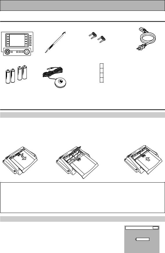
Checking the Supplied Accessories
Please check that you have received all of the following supplied accessories.
|
Touch Pen |
U-shaped connectors x 2 |
|
|
(attached to back of |
AC power cord |
|
Remote Control Unit |
(attached to the back |
amplifier) |
|
of the remote control) |
|
|
“AA” IEC LR6 |
|
Cushion for |
|
|
Remote x 4 |
|
|
batteries x 4 |
Microphone |
• Operating Instructions |
Preparing the Remote Control
Loading the batteries
Load the batteries into the remote control as shown below. The remote control uses a lot of power due to the LCD display so please use alkaline batteries. Depending on individual use you may have to change the batteries fairly often but most users should be able to get an average of 1-3 months of battery life. When you notice a decrease in the operating range or if the alarm sounds (see below), replace all batteries with new ones.
NOTE: After replacing the batteries, the touch panel will need re-adjusting (see p. 8-9).
1 |
2 |
·ª |
“AA” IEC LR6 |
3 |
|
batteries x 4 |
|||||
|
|
|
|
||
|
ª |
· |
|
|
|
|
· |
|
|
||
|
ª |
|
|
|
ª
·
\ \
CAUTION!
Incorrect use of batteries may result in such hazards as leakage and bursting. Observe the following precautions.
•Never use new and old batteries together.
•Insert the plus and minus sides of the batteries properly according to the marks in the battery case.
•Batteries with the same shape may have different voltages. Do not use different batteries together.
•When disposing of used batteries, please comply with governmental regulations or environmental public institution’s rules that apply in your country or area.
Remote Control Battery Alarm
When the batteries get too weak to operate the remote control properly an alarm will sound and a warning screen will appear on the remote. Change the batteries as shown above. This must be done within five minutes of the alarm sounding or all your remote control settings will be cleared.
Change Battery !! |
OK ? |
SIZE AA, LR6
6
En
Before You Start
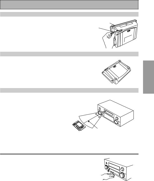
The Touch Pen & Lock
The touch pen is located in the back right-hand corner of the remote control. Take it out by sliding your finger along the bottom right edge of the remote control and then grasping the pen with thumb and forefinger.
The lock switch is located in the top right-hand corner on the back of the remote control. When this switch is set to LOCK you can’t use the buttons on the remote control. This is helpful to prevent you from mistakenly pushing a button. For normal use keep the switch set in USE.
Lock Switch
Touch pen
Remote Control Cushions
Apply the cushions to the feet of the remote control as shown in the diagram right.
Operating range of remote control unit
The area in which you can use the remote control to operate the VSA-AX10 is fairly large. To use, point the remote control toward the remote sensor on the front panel of this unit while within the range shown below.
Remote control may not function properly if: |
30 |
• There are obstacles between the remote control and |
|
the remote sensor. |
30 |
• |
Direct sunlight or fluorescent light is shining onto the |
|
|
remote sensor. |
|
• |
The amplifier located near a device emitting infrared |
7m |
|
rays. |
|
|
|
•Operated simultaneously with another remote control which uses infrared rays.
PREPARATION
Opening the Front Panel
To open the front panel push gently on the lower third of the panel with your finger.
7
En
Before You Start
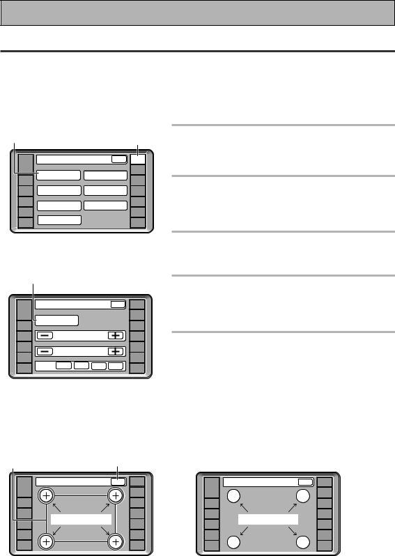
Setting Up the Remote Control
Try and get used to the touch-sensitive nature of the buttons on the remote control as well as the way in which different screens control different operations. You can move between the different screens with the function buttons on the left and right and/or certain buttons within each screen. The BACK button will always return the remote control to the previous screen. In the explanations below complete the TOUCH PANEL ADJUSTMENT setup to use the remote control properly. After that you can adjust various basic settings to suit your personal preferences.
3 |
|
|
|
|
|
2 |
1 |
Make sure the batteries are in the |
|
|
|
|
|
|
remote control (see page 6, if |
||
|
|
|
|
|
|
|
|
|
|
Remote Setup |
|
BACK |
SETUP |
|
necessary). |
||
|
|
|
|
|
|
REMOTE |
|
|
AMP |
|
|
|
|
|
|
|
|
|
|
LCD |
|
|
|
CD |
|
|
|
|
DIRECT FUNCTION |
|
|
|
|||
|
COMMANDER |
CD-R/ |
2 |
Press REMOTE SETUP on the remote |
||||
DVD/LD |
|
|
|
|||||
|
|
|
|
|
TAPE1 |
|||
VCR1 |
PRESET RECALL |
|
ITEM MEMO |
TUNER |
|
control. |
||
/DVR |
|
|
|
|
|
|
|
|
VCR2 |
LEARNING |
|
KEY LABEL |
VIDEO |
|
|||
|
|
|
|
Access to the different setup modes appear on your |
||||
VCR3 |
|
|
|
|
|
SAT |
|
|
TV |
MULTI OPERATION |
|
|
|
TV |
|
remote control screen. |
|
|
|
|
|
|
|
CONTROL |
|
|
|
|
|
|
|
|
|
3 |
Press the LCD COMMANDER button. |
|
|
|
|
|
|
|
|
The different types of possible adjustments will appear on |
4 |
|
|
|
|
|
|
|
the screen. |
|
|
|
|
|
|
4 |
Press the TOUCH PANEL |
|
|
|
|
|
|
|
|
||
|
LCD Commander |
|
BACK |
SETUP |
|
ADJUSTMENT button. |
||
|
|
|
|
|
|
REMOTE |
|
You must first align the touch panel to make sure the |
AMP |
|
|
|
|
|
|
|
|
|
TOUCH PANEL |
|
|
|
CD |
|
remote control responds properly when you touch it. |
|
|
|
|
|
|
|
|||
DVD/LD |
ADJUSTMENT |
|
|
|
CD-R/ |
|
||
|
|
|
|
|
TAPE1 |
|
|
|
|
|
|
|
|
|
|
|
|
VCR1 |
|
LCD CONTRAST |
|
TUNER |
5 |
Press each cross point in the middle to |
||
/DVR |
|
|
|
|
|
|
||
VCR2 |
|
LCD TIMER : 10 SEC |
|
VIDEO |
|
align the remote control touch panel |
||
VCR3 |
|
|
SAT |
|
||||
|
|
|
|
|
|
|||
TV |
BEEP |
OFF |
1 |
2 |
3 |
CONTROL |
|
with the LCD panel underneath. |
|
TV |
|
|
|||||
|
|
|
|
|
|
|
|
This adjustment will make sure your remote control is |
|
|
|
|
|
|
|
|
calibrated correctly. |
|
|
|
|
|
|
|
|
When you've touched all four cross points the screen will |
|
|
|
|
|
|
|
|
show the word "COMPLETE" and automatically return to |
|
|
|
|
|
|
|
|
the LCD COMMANDER screen. |
5 |
BACK |
|
|
|
|
|
Touch Panel Adjust |
BACK |
REMOTE |
|
Touch Panel Adjust |
BACK |
REMOTE |
SETUP |
|
SETUP |
||||
AMP |
|
|
|
AMP |
|
|
|
|
CD |
|
|
|
CD |
DVD/LD |
|
CD-R/ |
|
DVD/LD |
|
CD-R/ |
|
TAPE1 |
« |
|
TAPE1 |
||
|
|
|
|
|||
VCR1 |
|
TUNER |
VCR1 |
|
TUNER |
|
/DVR |
|
/DVR |
|
|||
|
|
|
|
|||
TOUCH CROSS POINT |
|
VIDEO |
COMPLETE |
|
|
|
VCR2 |
|
|
VCR2 |
|
VIDEO |
|
VCR3 |
|
SAT |
|
VCR3 |
|
SAT |
TV |
|
TV |
|
TV |
|
TV |
|
CONTROL |
|
|
CONTROL |
||
|
|
|
|
|
8
En

Before You Start
6Decide which other adjustments you‘d like to make and press those buttons. The different possibilities are:
7
|
LCD Commander |
|
BACK |
REMOTE |
||
AMP |
|
SETUP |
||||
|
TOUCH PANEL |
|
|
|
CD |
|
|
|
|
|
|
||
DVD/LD |
ADJUSTMENT |
|
|
|
CD-R/ |
|
|
|
|
|
|
TAPE1 |
|
|
|
|
|
|
|
|
VCR1 |
|
LCD CONTRAST |
|
|
TUNER |
|
/DVR |
|
|
|
|||
|
|
|
|
|
|
|
VCR2 |
|
LCD TIMER : 10 SEC |
|
VIDEO |
||
|
|
|
|
|||
VCR3 |
|
|
|
|
|
SAT |
TV |
BEEP |
OFF |
1 |
2 |
3 |
TV |
|
|
|
|
|
CONTROL |
|
|
|
|
|
|
|
|
6
LCD CONTRAST: You can lighten or darken the contrast on the remote control screen. Use the – /+ buttons to change the contrast.
LCD TIMER: In order to save the battery a timer will automatically turn the remote control off after a set amount of time if no commands are entered. You can choose how long the idle remote control will stay on before the timer turns it off. You can set this function in a range of 5-60 seconds. The default setting is 10 seconds. Use the – /+ buttons to adjust the number of seconds for the timer setting.
(The REMOTE SETUP screen and its sub-screens are all fixed to stay on 60 seconds. If no command is entered they will turn off after 60 seconds.)
BEEP: When you have sent a command (pushed a button) the remote control will beep once. You can choose the sound of the beep from three different possibilities here by pushing the appropriate button (1,2,3). You can also turn the beep sound off.
7When you are finished with the adjustments press the BACK button to go back to the Remote Setup screen.
PREPARATION
Remote Control Backlight
1 |
|
|
|
|
|
|
|
|
|
|
|
|
|
use |
lock |
|
|
|
|
|
|
|
TV |
|
|
|
|
|
REMOTE |
CONTROL |
|
LIGHT |
AMP |
|
|
|
SETUP |
|
|
|
|
|
|
|
|
||
|
|
|
|
|
CD |
|
FUNCTION |
|
|
|
|
|
|
|
|
|
DVD/LD |
|
|
|
CD-R/ |
|
CH + |
|
|
|
|
TAPE1 |
|
||
|
|
|
|
|
|
||
|
VCR1 |
|
|
|
TUNER |
|
CH – |
|
/DVR |
|
|
|
|
|
|
|
VCR2 |
|
|
|
VIDEO |
|
VOL + |
|
VCR3 |
|
|
|
SAT |
|
VOL – |
|
TV |
|
|
|
TV |
|
|
|
|
|
|
CONTROL |
FUNCTION |
||
|
|
|
|
|
MASTER VOLUME |
|
|
|
|
MULTI |
SYSTEM |
|
+ |
|
|
|
STANDBY/ON |
OPERATION |
OFF |
MUTING |
|
|
|
1Decide whether you’d like to have the backlight on or not and use the LIGHT switch to turn it on or off.
This button turns the light on or off. If you leave it on the remote screen is easier to see but uses more energy and thus wears the batteries down quicker.
ENTER
–
9
En

Quick Start Guide Part1
Home Theater: The Basics
Most consumers are used to using stereo equipment to listen to music but many people are not used to home theater systems that give you many more options when listening to soundtracks. In fact, home theater is not really complicated and this little guide should give you an understanding of the basics.
The main reason why it seems so difficult is that there are three different factors involved in home theater and each will contribute to what kind of sound you get.
These factors are:
1)The equipment you are using for your home theater setup. Particularly important is the number of speakers you are using. We call this your speaker configuration.
2)The 'source' material you are using. This is the actual product (like a DVD) or broadcast (like cable TV) you are listening to/watching. We call this the source.
3)The last factor is the listening mode you choose on the VSA-AX10 Amplifier. These are explained below and in subsequent chapters but most likely the STANDARD (default) setting will be fine.
Let's start with the home theater setup you have in your home.
1)Your Home System
The heart of your system is the VSA-AX10 Amplifier and it is very flexible in getting you theater-like surround sound. You can use this Amplifier with anywhere from two to seven speakers (front left, front right, center, surround left and right, and surround back left and right) and a subwoofer to get home theater surround sound. We recommend you use seven speakers and a subwoofer. If this is not possible follow the instructions in "Auto Surround Setup" in the "Quick Start Guide" and you will be able to get good surround sound. Also, a DVD player is essential for home theater and you can also hook up satellite or cable TV tuner to this Amplifier and get a more home theater-like sound from these sources.
2) The Source Material
DVDs have become the basic source material for home theater because they offer excellent sound and picture quality, and allow users to enjoy home theater soundtracks with more than two channels of audio. For example, Dolby Pro Logic plays back four channels (front left, front right, center and a single channel for both surround speakers), Dolby Digital, MPEG and DTS sources usually have six discrete channels (front left, front right, center, surround left and right and a channel that powers the subwoofer) of sound. Since the subwoofer channel is only for bass sounds, this multichannel setup has been named 5.1 channel sound.
It is important you consult the manual that came with your DVD player as well to make sure the player is outputting a surround soundtrack and all the other settings are appropriate for your home theater.
3) The Listening Modes
This Amplifier has many different listening modes and they are designed to cover all the speaker configurations and types of sources you might be using. In general, if you follow the recommended advice and have seven speakers and a subwoofer hooked up, in most cases the STANDARD listening mode is the easiest way to get realistic home theater sound. This is the default setting so you don't have to do anything.
To listen to music in stereo simply choose the STEREO listening mode. Other possibilities (like listening to a stereo CD with all seven speakers or taking a stereo source and getting multichannel home theater-like sound) are explained in listening modes (pages 49–52).
Conclusion
These are the three basic factors that contribute to your home theater sound. The easiest thing is to hook up seven speakers and a subwoofer and simply play your DVDs with STANDARD 7.1 mode. This will give you realistic and enjoyable home theater sound. First hook up your equipment, like your DVD player, TV and speakers. Then follow the instructions to set up your system for surround sound. It is very important you do one of the surround sound setups to get optimal sound from your Amplifier.
For more details on any of the information presented here check the main section of the manual.
10
En
Quick Start Guide Part1
Before making or changing the connections, switch off the power and disconnect the power cord from the AC outlet.
1 Hooking Up Your DVD Player & TV
In order to use Dolby Digital, MPEG or DTS soundtracks you need to hook up your DVD player with digital audio connections. You can do this by either a coaxial or an optical connection, you don’t need to do both. The quality of these two types of connections is the same but since some DVD players only have one type of digital terminal you need to figure out which yours has and hook it up to the appropriate terminal on the Amplifier. In order to do this you will need the proper cable. For coaxial connections you can use a regular Phono video cord or the specially-made coaxial cords, they have the same type of plugs. For optical connections you will need a special optical cable which you can buy at your local stereo store. For more detail on cords/cables see page 25. You should also hook up your DVD player with analog audio connections. Use regular Phono stereo cords for these connections. Also hook up the video connection on your DVD player and your TV to this Amplifier. For your TV it's easiest to use a regular composite Phono video cord, as shown below. It is important that you hook up your TV (or monitor) in order to see a video image as well as the on screen displays (OSDs) shown by this Amplifier (for more see page 18).
Digital Connections
Some DVD players have both coaxial and optical terminals, but there is is no need to connect both. If your DVD player has a coaxial terminal (not a PCM-only output) for the audio out hook it up using this terminal. Follow the diagram below using DIGITAL IN 1. This is the best scenario, as you will be able to follow the default settings of this amplifier and won't need to assign the digital inputs.
If your DVD player only has an optical terminal for the audio output you can hook it up using one of the DIGITAL IN terminals between 4-7 (for example, DIGITAL IN 4). In this case, you will need to assign the digital input (which means tell the amplifier which input you used for your DVD digital audio). See page 13 for this.
Phono video cord
4 |
|
MONITOR |
|
(SAT) |
OUT |
|
|
IN
|
Phono stereo cord |
ANALOG |
|
|
|
|
|
|
|
|
STEREO |
|
|
R |
R |
|
|
L |
L |
R |
L |
|
VIDEO |
|
|
|
|
|
|
|
VIDEO |
|
|
|
OUT |
|
DVD |
IN |
|
|
/LD |
|
|
|
IN |
|
|
DVD player
IN 3 |
(CD) |
DIGITAL |
|
OUT |
ª |
PCM/2DIGITAL |
|
DIGITAL |
|||
|
|
|
|
MONITOR |
|
|
|
/DTS/MPEG |
OUT |
IN |
AC OUTLET |
|
|
|
OUT |
|
|
|
|
|
|
CONTROL |
|
MONITOR |
|
|
|
|
|
|
OUTPUT |
|
|
|
2 |
|
|
|
|
|
|
|
DVD |
|
|
Phono video cord |
|
|
|||
|
|
|
|
|
R |
AUDIO L |
|
|
|
|
|
OUT |
|
|
|
FRONT |
|
|
|
|
|
|
|
PHONO |
|
|
|
|
|
|
IN |
|
|
|
|
|
|
||
|
|
|
1 |
|
|
|
|
|
|
|
|
|
AM LOOP |
R |
|
|
|
||
|
|
|
OUT |
IN |
|
|
|
|
|
|
/LD |
IN |
1 |
Y |
ANTENNA |
|
|
|
|
IN 2 |
(TV) |
|
|
|
|
|
AUDIO |
|
|
|
IN |
|
Y |
MONITOR |
ANTENNA |
|
|
|
|
|
TAPE1 |
IN |
|
|
|
|
IN |
|
TV |
IN |
|
OUT |
FM |
|
|
|
|
||
|
|
7 |
(CD-R/ |
CD |
|
|
|
|
POWER AMP |
|
|
|
|
|
|
|
|
|
|
|
|
IN |
/MD) |
|
|
|
R |
L |
|
|
IN |
|
PB |
PB |
75Ω UNBAL |
CENTER |
|
|
|
|
|
|
|
|
|
|
|
|
|
|
|
|
|
||||||
|
|
6 |
|
TUNER |
|
|
|
FRONT |
|
SAT |
|
|
|
|
|
|
|
(not a PCM-only |
|
|
|
IN |
(VCR2) |
IN |
|
|
CENTER |
L |
|
|
IN |
IN |
IN |
IN |
|
|
|
AC IN |
|
|
|
(VCR1 |
OUT |
|
|
|
|
OUT |
OUT |
|
|
|
|||||||
|
|
|
|
|
|
R |
|
|
|
|
PR |
PR |
|
|
|
|
|
||
|
|
5 |
|
|
|
|
|
|
|
|
|
|
|
|
|
L |
|
|
|
|
(DVD |
4 |
/DVR) |
REC |
|
|
|
SUB W. |
|
/DVR |
|
2 |
3 |
|
|
|
output) |
||
|
|
/MD |
|
|
|
|
|
|
Y |
|
ROUND |
|
|
||||||
IN 1 |
|
IN |
|
CD-R/ |
|
|
1 |
2 |
|
|
VCR1 |
|
Y |
|
SUR- |
SPEAKERS |
|
||
|
IN |
|
PLAY |
|
|
|
|
|
|
PB |
PB |
|
|
||||||
|
|
|
TAPE1 |
|
|
|
|
|
|
|
|
|
|
|
|
|
|
||
|
|
(SAT) |
IN |
|
|
|
|
PRE OUT |
|
IN |
IN |
|
|
|
|
|
|
|
|
|
|
|
|
OUT |
|
|
(Single) |
SUR- |
|
|
|
|
|
|
R |
ª ı |
|
|
|
|
|
IN 3 |
(CD) |
|
|
|
ROUND |
|
OUT |
OUT |
|
|
|
|
· |
|
|||
|
|
REC |
|
|
|
|
|
|
|
|
|
|
|
||||||
|
|
|
|
TAPE2 |
|
|
R |
L |
|
|
VCR2 |
|
PR |
PR |
|
|
|
|
|
|
|
|
|
MONITOR |
|
|
|
SUR- |
|
|
|
COMPONENT VIDEO |
|
L |
(Single) |
L |
|
||
|
|
IN 2 |
(TV) |
IN |
|
|
|
ROUND |
|
IN |
IN |
|
|
|
|||||
2RF |
|
|
|
|
|
BACK |
|
|
|
|
You only need to make |
||||||||
|
IN 1 |
/LD) |
PLAY |
|
L |
R |
L (Single) |
|
OUT |
OUT |
|
|
|
SUR- |
|
|
|||
IN |
|
R |
|
|
CENTER |
|
|
|
|
ROUND |
|
|
|||||||
|
|
|
|
FRONT |
|
|
SUB W. |
|
|
|
|
|
|
|
|
|
|||
|
|
|
(DVD |
|
|
|
|
|
|
|
|
|
|
|
|
BACK |
|
|
|
|
|
|
(For LD) |
SUR- |
|
L |
R |
SUR- |
R AUDIO L |
VCR3 |
|
S2 VIDEO |
RS-232C |
|
R |
|
R |
one DIGITAL connection. |
|
|
|
|
R |
|
L |
|
VIDEO |
|
|
|
|
|
|||||||
|
|
2RF |
(DVD |
ROUND |
|
|
|
ROUND |
|
IN |
IN |
|
|
|
|
|
|
|
|
|
|
IN |
/LD) |
|
|
|
|
|
BACK |
|
|
|
|
|
|
|
|
||
ASSIGNABLE |
|
|
|
|
|
|
(Single) |
|
|
|
|
|
|
|
|
|
|
||
ASSIGNABLE |
|
|
MULTI CH INPUT |
|
|
|
|
|
|
|
coaxial cord |
|
|
||||||
|
|
|
|
|
|
|
|
|
|
|
|
|
|
|
|
|
|||
optical cord
VIDEO INPUT
START QUICK GUIDE
11
En
Quick Start Guide Part1
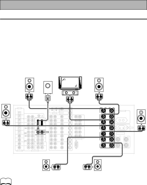
2 Speaker Connections
Home theater is designed to be setup with five, or seven speakers (front left & right; center; surround left & right; and, optimally, surround back left & right) and a subwoofer, but you can use this amplifier with fewer speakers. Hook up the speakers you have to the A speaker terminals on the back of the amplifier. If you only have two speakers hook them up as "FRONT." If you have three hook up the single speaker as "CENTER." Follow the diagram below in order to hook up all your speakers. A center speaker is very important for watching films because in digital soundtracks the dialog comes from the center speaker. If you do not have a center speaker you must tell the amplifier the center channel is off or when you listen to digital soundtracks you won't hear any dialog. This can be done automatically by following the Auto Surround Sound Setup instructions from page 14 in this Quick Start Guide.
If possible, use surround back speakers. These speakers are important to take full advantage of all the sound channels on new, eight channel home theater DVDs. The diagram below also explains how to hook up a subwoofer which provides realistic bass sounds. For the subwoofer use a mono (single plug) Phono cord and for the other speakers use regular speaker cords. See pages 95–96 for advice on speaker placement.
Make sure you connect the speaker on the right to the R terminal and the speaker on the left to the L terminal. Also make sure the positive and negative (+/–) terminals on the amplifier match those on the speakers.
|
|
|
|
|
|
Powered |
|
|
|
|
|
|
|
|
|
|
|
Front |
|
|
|
|
subwoofer |
|
TV/monitor |
|
|
|
Front |
|
|
|
|||
|
|
|
|
|
|
|
|
|
|
|
|
||||||
speaker |
|
|
|
|
|
|
|
|
|
|
|
speaker |
|
|
|
||
(Left) |
|
|
|
|
|
|
|
|
|
|
|
(Right) |
|
|
|
||
|
|
|
|
|
|
|
|
|
|
|
Center |
|
|
|
|
|
|
Surround |
|
|
|
|
|
|
|
|
|
|
speaker |
|
|
|
|
|
|
|
|
|
|
|
INPUT |
|
|
|
|
|
|
|
|
|
|
|
|
speaker |
|
|
|
|
|
|
|
|
|
|
|
|
|
|
|
|
Surround |
(Left) |
|
|
|
|
|
|
|
|
|
|
|
|
|
|
|
|
|
|
|
|
|
|
|
|
|
|
|
|
|
|
|
|
|
|
speaker |
|
DIGITAL |
|
|
|
|
|
|
MONITOR |
|
|
|
· |
Å |
ª |
|
|
(Right) |
PCM/2DIGITAL |
|
|
|
|
|
|
OUT |
|
|
|
L |
|
|
|
|
|
|
|
/DTS/MPEG |
|
|
|
|
OUT |
IN |
|
|
|
|
|
|
|
AC OUTLET |
|
|
|
2 |
|
|
|
|
|
|
MONITOR |
|
|
|
|
|
|
|
|
|
|
OUT |
|
|
|
|
CONTROL |
OUT |
|
|
|
FRONT |
|
|
|
|
|
|
|
|
|
R |
AUDIO L |
|
|
|
|
|
|
|
|
|
|
|
|
|
|
|
PHONO |
|
|
|
|
|
IN |
|
|
|
|
|
|
|
||
|
1 |
|
|
|
|
DVD |
|
|
|
R |
|
|
|
|
|
||
|
|
|
|
|
|
IN |
|
Y |
|
|
|
|
|
||||
|
OUT |
IN |
|
|
|
|
/LD |
|
1 |
|
|
|
|
|
|||
|
|
|
|
|
|
AUDIO |
IN |
|
|
Y |
MONITOR |
|
|
|
|
|
|
|
|
|
|
|
|
|
|
|
|
|
|
|
|
|
|
||
7 |
(CD-R/ |
CD |
|
|
|
POWER AMP |
TV |
|
|
|
OUT |
|
|
|
|
|
|
|
TAPE1 |
IN |
|
|
|
IN |
IN |
|
|
|
|
|
|
|
|
|
|
IN |
/MD) |
|
|
|
R |
L |
IN |
|
|
PB |
PB |
CENTER |
|
|
|
|
|
|
|
|
|
|
|
|
|
|
|
|
|
||||||
6 |
(VCR2) |
TUNER |
|
|
|
FRONT |
SAT |
IN |
|
|
|
|
|
|
|
|
|
IN |
IN |
|
|
R |
L |
IN |
|
PR |
PR |
|
|
|
|
|
|
||
|
|
|
|
|
|
|
|
|
|
|
|
|
|||||
5 |
(VCR1 |
OUT |
|
|
|
CENTER |
OUT |
OUT |
|
IN |
IN |
L |
|
|
|
|
AC IN |
|
REC |
|
|
|
|
|
|
|
|
|
|||||||
|
/DVR) |
|
|
|
|
|
|
|
|
2 |
3 |
|
|
|
|
|
|
IN |
|
CD-R/ |
|
|
|
|
VCR1 |
|
|
Y |
Y |
SUR- |
|
|
|
|
|
4 |
|
TAPE1 |
|
|
|
SUB W. |
/DVR |
|
|
|
|
|
|
|
|
|
|
|
/MD |
|
|
|
|
|
|
|
ROUND |
|
|
|
|
|
|||
(SAT) |
|
|
|
PRE OUT |
IN |
IN |
|
|
|
|
|
|
|
|
|||
|
IN |
|
|
|
|
|
|
|
|
|
SPEAKERS |
|
|||||
IN |
|
PLAY |
|
|
1 |
2 |
|
|
|
PB |
PB |
R |
|
|
|
||
|
|
OUT |
|
|
(Single) |
SUR- |
|
|
|
|
|
|
|
|
|
|
|
IN 3 |
(CD) |
|
|
|
ROUND |
OUT |
OUT |
|
|
|
|
|
|
ª |
ı |
· |
|
REC |
|
|
|
|
|
|
|
|
|
|
|||||||
|
|
TAPE2 |
|
|
R |
L |
VCR2 |
|
|
PR |
PR |
|
|
|
|
|
|
|
|
MONITOR |
|
|
|
SUR- |
|
|
COMPONENT VIDEO |
L |
(Single) |
|
|
L |
|||
IN 2 |
(TV) |
IN |
|
|
|
IN |
IN |
|
|
|
|||||||
|
|
|
BACK |
|
|
|
|
|
|||||||||
|
|
|
|
|
|
ROUND |
|
|
|
|
|
|
|
|
|
|
|
|
|
PLAY |
|
|
R |
L (Single) |
|
|
|
|
|
SUR- |
|
|
|
|
|
|
|
FRONT |
|
|
SUB W. |
CENTER |
|
|
|
|
|
ROUND |
|
|
|
|
|
IN 1 |
(DVD |
|
|
|
|
|
OUT |
OUT |
|
|
|
BACK |
|
|
|
|
|
/LD) |
|
|
|
|
|
|
|
|
|
|
|
|
|
|
|||
|
|
R |
|
L |
|
|
VCR3 |
|
|
|
|
R |
|
|
|
|
R |
|
|
SUR- |
|
|
|
SUR- |
|
|
|
|
|
|
|
|
|||
2RF |
(DVD |
ROUND |
|
|
|
ROUND |
IN |
IN |
|
|
|
|
|
|
|
|
|
IN |
/LD) |
|
|
|
|
BACK |
|
|
|
|
|
|
|
|
|
||
R |
|
L |
R |
L (Single) |
|
|
|
|
|
|
|
|
|
|
|
||
|
(For LD) |
|
|
|
|
RS-232C |
|
|
|
|
|
|
|
||||
|
|
|
|
|
R AUDIO L |
|
VIDEO |
S2 VIDEO |
|
|
|
|
|
|
|
||
ASSIGNABLE |
|
|
MULTI CH INPUT |
|
|
|
|
|
|
|
|
|
|
|
|
||
Surround back |
Surround back |
speaker (Left) |
speaker (Right) |
memo |
• Please use speakers with a nominal impedance rated 6Ω -16Ω . |
|
• If you only have one surround back speaker hook it up to the left surround back terminal.
•If you use a THX certified subwoofer use the THX INPUT jack on the subwoofer (if your subwoofer has one) or switch the filter position to THX on your subwoofer.
•When you attached your speaker wire to the speaker terminal make sure that not even one strand of wire touches the back of the amplifier. If this happens it could short out the amplifier.
12
En
Quick Start Guide |
Part1 |
|
7 Speaker terminals |
|
|
1 Twist exposed wire |
2 Loosen speaker terminal |
3 Tighten |
strands together tightly. |
and insert exposed wire. |
terminal. |
10mm |
|
|
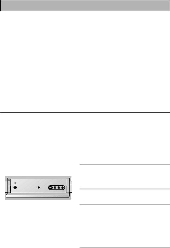
3 Setting up the Main Unit
START QUICK GUIDE
1Connect the supplied AC power cord to the back of the main unit and plug the other end into a wall outlet (don't use any other power cord than the one that came with this amplifier).
2Press the POWER ON/OFF button to put the amplifier in ON mode.
3 Press the  STANDBY/ON button to switch the amplifier ON.
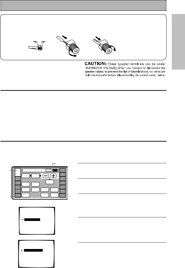
4 Assigning the Digital Inputs
This is only necessary if you did not hook up your DVD player to DIGITAL IN 1 using a coaxial cable, as in the diagram on p.11, but rather connected it to one of the optical digital inputs. The following example shows how to assign the DIGITAL IN 3 jack to DVD.
1 |
|
|
|
|
2 |
|
|
Amplifier |
MAIN |
SUB |
REMOTE |
||
AMP |
SETUP |
|||||
|
BASS/ |
|
|
CD |
||
|
|
TONE |
|
|
||
|
|
ATREBLE |
|
|
|
|
|
|
|
|
|
CD-R/ |
|
|
DVD/LD |
|
|
|
|
TAPE1 |
|
VCR1 |
|
|
EFFECT/ |
|
|
|
DISPLAY |
VIDEO |
CH SEL. |
TUNER |
||
|
/DVR |
|||||
|
|
DIMMER |
SELECT |
|
|
|
|
VCR2 |
|
SPEAKER |
|
INPUT |
VIDEO |
|
|
STATUS |
LOUDNESS |
|
||
3 |
VCR3 |
|
A/B |
|
ATT. |
SAT |
TV |
SYSTEM |
|
TAPE 2 |
SIGNAL |
TV |
|
SETUP |
|
MONITOR |
SELECT |
CONTROL |
||
|
|
|||||
|
|
|
|
|
|
|
4 |
|
System Setup |
|
|
|
|
|
|
[ Auto Surround Setup ] |
|
|
||
|
|
[1. Input Assign ] |
|
|
|
|
|
|
[2. Surround Setup] |
|
|
||
|
|
[3. Expert Setup] |
|
|
|
|
|
|
[4. THX Audio Setup] |
|
|
||
|
|
[Exit] |
|
|
|
|
5 |
|
1.Input Assign |
|
|
|
|
|
|
|
|
|
||
|
|
[ 1.Digital-In Select ] |
|
|
||
|
|
[ 2.C' nent Video In ] |
|
|
||
|
|
[Return] |
|
|
|
|
1Turn on the amplifier and your TV, press AMP on the remote control.
2Press the SUB button on the AMPLIFIER remote control screen.
3Press the SYSTEM SETUP button.
The SYSTEM SETUP menu appears on your TV (if it doesn't, refer to page 11 to make sure you have properly connected the amplifier to your TV).
4Looking at the on-screen display on your TV, use the 5∞ buttons to select INPUT ASSIGN. Press the ENTER button.
5DIGITAL IN-SELECT should be selected, if not use the 5∞ buttons to select it. Press the ENTER button.
13
En
Quick Start Guide Part2
6
7
1.1. Digital-In |
Select |
|
|
|
Digital-1 |
[ DVD/LD ] |
|||
Digital-2 |
[ |
TV |
] |
|
Digital-3 |
[ |
CD |
] |
|
Digital-4 |
[ |
SAT |
] |
|
Digital-5 |
[ |
VCR1 |
] |
|
Digital-6 |
[ |
VCR2 |
] |
|
Digital-7 |
[ |
CD-R |
] |
|
RF IN |
[ DVD/LD ] |
|||
[Return] |
|
|
|
|
1.1. Digital-In |
Select |
|
|
|
Digital-1 |
[ |
OFF |
] |
|
Digital-2 |
[ |
TV |
] |
|
Digital-3 |
[ |
CD |
] |
|
Digital-4 |
[ |
DVD/LD |
] |
|
Digital-5 |
[ |
VCR1 |
|
] |
Digital-6 |
[ |
VCR2 |
] |
|
Digital-7 |
[ |
CD-R |
] |
|
RF IN |
[ DVD/LD ] |
|||
[Return]
6The default setting for the DIGITAL-4 jack is SAT.
7Use the 2 3 buttons to select DVD/
LD.
8Select RETURN with the 5∞ buttons and press ENTER.
You will return to the SYSTEM SETUP menu.
9 Choose EXIT with the 5∞ buttons and press ENTER.
The amplifier exits the setup process.
1 Auto Surround Sound Setup
If setting up your surround sound speakers seems like it's going to be an involved task you only need to use this quick, automatic method to achieve good surround sound. You'll need to hook up the microphone provided so that the amplifier can hear and judge the distance, size, sound character and sound pressure level of the speakers and thus know what settings to make.
Follow the step-by-step guide to setting up your surround sound below. This will customize the surround sound for your listening environment. After you get used to the system it is a good idea to make more advanced settings as explained in "Expert Setup" (page 82). Also, if you want to personalize your surround sound setups by making the settings manually go to "Setting up for Surround Sound" (page 37). Make sure all the components you need, especially speakers, have been properly connected before you do the steps described here. Use the arrow buttons (5∞) and the ENTER button on the remote control to navigate the on-screen display (OSD) on your TV.
2 |
1 Switch on the amplifier and your TV. |
|
Make sure your TV is set to this amplifier as you will |
||
|
||
|
use the on-screen displays (OSDs) on your TV to |
|
|
follow these instructions. |
2 Hook up the microphone to the Front Panel.
3 Place the microphone at your normal listening position.
If you have a tripod, attach the microphone to it and use that to get the mic to ear level at your normal listening position.
If you don't have a tripod use a table or chair to put the microphone at the same height as you usually listen to your system from.
4 If you have a subwoofer turn it on.
14
En
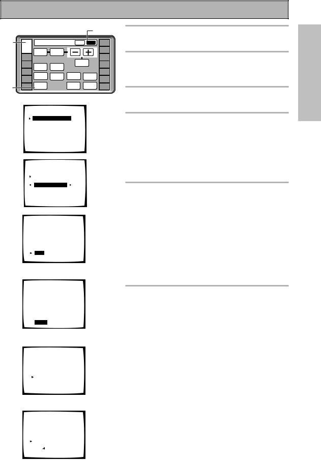
5 |
|
|
|
|
|
5 |
|
|
Amplifier |
|
MAIN |
SUB |
CD |
||
|
|
|
SETUP |
||||
|
|
|
|
|
|
|
REMOTE |
|
AMP |
|
|
|
|
|
|
|
|
TONE |
BASS/ |
|
|
|
|
|
|
ATREBLE |
|
|
|
||
|
|
|
|
|
CD-R/ |
||
|
DVD/LD |
|
|
|
|
|
TAPE1 |
|
VCR1 |
|
|
|
EFFECT/ |
|
|
|
DISPLAY |
VIDEO |
CH SEL. |
TUNER |
|||
|
/DVR |
||||||
|
|
DIMMER |
SELECT |
|
|
|
|
|
VCR2 |
|
SPEAKER |
|
INPUT |
VIDEO |
|
|
|
STATUS |
LOUDNESS |
|
|||
|
VCR3 |
|
A/B |
|
|
ATT. |
SAT |
6 |
|
SYSTEM |
|
|
TAPE 2 |
SIGNAL |
TV |
TV |
SETUP |
|
|
MONITOR |
SELECT |
CONTROL |
|
|
|
|
|||||
|
|
|
|
||||
7 |
System Setup |
|
|
|
|
||
|
|
|
|
|
|||
|
[ Auto Surround Setup ] |
|
|
||||
|
[1. Input Assign] |
|
|
|
|
||
|
[2. Surround Setup] |
|
|
|
|||
|
[3. Expert Setup] |
|
|
|
|
||
|
[4. THX Audio Setup] |
|
|
|
|||
|
[Exit] |
|
|
|
|
|
|
8 |
Auto Surround Setup |
|
|
||||
|
|
|
|||||
|
Speaker System Select |
|
|
||||
|
[ |
Normal Surround |
] |
|
|
||
|
[Go Next] |
|
|
|
|
||
|
[Return] |
|
|
|
|
|
|
10 |
Auto Surround Setup |
|
|
|
|||
|
•Connect |
microphone |
|
|
|||
|
•Please be quiet |
|
|
|
|
||
|
•Move obstacles |
away |
|
|
|||
|
•If you have a subwoofer |
|
|
||||
|
|
turn power on |
and |
|
|
||
|
|
turn |
volume |
up |
|
|
|
|
|
[Start] |
|
|
|
|
|
|
|
[Cancel] |
|
|
|
|
|
|
|
|
\ |
|
|
|
|
|
Auto Surround Setup |
|
|
||||
Please Wait
Caution!!
Test tone is output loudly.
[Cancel]
\ |
|
|
||||||
Auto Surround Setup |
|
|||||||
|
Now Analyzing••• |
|
||||||
|
|
|
|
|
|
|
|
|
Environment Check |
|
|||||||
Ambient Noise |
[OK] |
|||||||
Microphone |
[OK] |
|||||||
Speaker Level |
[OK] |
|||||||
[ |
|
|
|
] |
|
|
|
|
Cancel |
|
|||||||
Quick Start Guide Part2
5Press AMP then press the SUB button on the remote control.
6Press the SYSTEM SETUP button and use the on-screen display (OSD) that appears on your TV.
7The arrow should be pointing at AUTO SURROUND SETUP, press ENTER.
8NORMAL SURROUND should be selected. (Use the 2 3 buttons to
select it if it isn't.) Use the 5∞ buttons to select GO NEXT and press ENTER.
For Bi-amp settings choose FRONT BI-AMP 5.1 and follow the directions from step 3 on page 39.
RETURN brings you back to the system setup menu.
9Some auto setup instructions will be listed, make sure to follow them.
Make sure you have: hooked up the microphone and moved obstacles to the speakers out of the way. If you have a subwoofer make sure it is turned on and has the volume turned up.
WARNING: The test tones are very loud!! Make sure there are no infants or small children in the room and that no one who will be scared, upset or injured by loud noise is present. You yourself may want to wear earplugs. It is possible to lower the volume of test tones, but this could result in incorrect speaker settings.
10 If you have followed all setup instructions and warnings above make sure that the arrow is pointed to START and press ENTER. Be prepared for loud test tones.
Try to be as quiet as possible after hitting ENTER. The test tones may take up to 30 seconds.
The volume automatically increases to 0 dB, then the system will output some test tones and establish ambient noise levels, the microphone status, and what speakers you hooked up.
START QUICK GUIDE
\ |
|
|
||||
|
Check!! |
|
||||
|
Front |
|
|
[ YES ] |
|
|
|
Center |
|
|
[ YES ] |
|
|
|
Surround |
[ YES ] |
|
|||
|
SurrBack |
[ YESX2] |
|
|||
|
Subwoofer |
[ YES ] |
|
|||
[ |
|
] |
|
|
||
OK,Go Next |
|
|
||||
|
[Retry] |
|
|
|
|
|
[ERR Fix |
SP.] |
|
15 |
|||
[Return to |
Menu] |
|||||
|
||||||
En
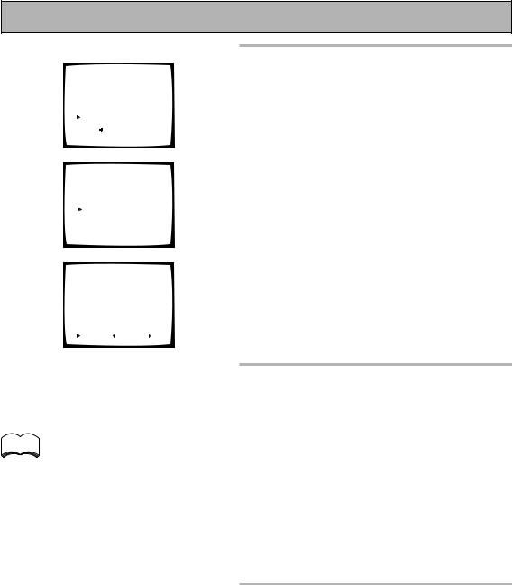
Quick Start Guide Part2
11 |
|
|
|
|
Check!! |
|
|||||
|
|
Front |
|
|
|
[ YES ] |
|||||
|
|
|
Center |
|
|
|
[ YES ] |
||||
|
|
|
Surround |
[ YES ] |
|||||||
|
|
|
SurrBack |
[ YESX2] |
|||||||
|
|
|
Subwoofer |
[ YES ] |
|||||||
[ |
|
|
|
|
|
] |
|
|
|
||
|
OK,Go Next |
|
|
|
|||||||
|
[Retry] |
|
|
|
|
|
|
||||
[ERR Fix |
SP.] |
|
|||||||||
[Return |
to Menu] |
|
|||||||||
Auto Surround Setup |
|
||||||||||
|
|
|
Now Analyzing••• |
|
|||||||
Surround |
|
|
|
|
|
|
|
|
|||
|
|
Analysis |
|
|
|||||||
Speaker |
Systems |
[OK] |
|||||||||
Channel |
Delay |
[OK] |
|||||||||
Channel |
Level |
[OK] |
|||||||||
Acoustic |
Cal |
EQ |
[OK] |
||||||||
[ |
|
|
|
] |
|
|
|
|
|
|
|
|
Cancel |
|
|
|
|
|
|
||||
Speaker |
Systems Check |
||||||||||
” |
Normal |
Surround |
” |
||||||||
Front |
|
|
|
[SMALL] |
|||||||
Center |
|
|
|
[SMALL] |
|||||||
Surround |
|
|
|
[SMALL] |
|||||||
SurrBack |
|
|
|
[SMALLX2] |
|||||||
Subwoofer |
|
|
[ YES |
] |
|||||||
|
|
|
|
||||||||
[ |
Next |
] |
( |
Back/Next |
) |
||||||
[Return] |
|
|
|
|
|
|
|||||
11 Check the speaker settings on the OSD
If they match your speaker configuration make sure OK,GO NEXT is selected and press ENTER. The test tones will be output loudly again. The test tones may take up to 5 minutes this time. After they have finished, you see the SPEAKER SYSTEMS CHECK screen. If you want to view the settings select NEXT and press ENTER repeatedly. If not, simply go to step 13.
If they do not match the speaker configuration you hooked up and you want to try again select RETRY with 5∞ buttons and press ENTER. Follow the instructions above from step 10.
If the speaker settings do not match the speaker configuration you connected and you want to input the settings manually select ERR=FIX SP with the 5∞ buttons, press ENTER and go to step 12.
If you see an ERR message in the right side column, there may be a problem with the speaker connection. If selecting RETRY doesn't fix the problem, turn off the power and check the speaker connections.
memo
•Make sure the room environment follows the guidelines displayed on the OSD during auto setup. If the room environment is not optimal for auto setup (too much ambient noise, obstacles blocking the speakers from the microphone, etc.) the final settings may be incorrect. Check for household appliances (air conditioner, fridge, fan, etc.) that may be affecting the environment and switch them off if necessary.
•Screens will turn off after three minutes and the amplifier will automatically exit from the setup process.
•If you leave CHECK!! or other error message on the screen for three minutes, or you choose CANCEL at anytime during the setup, the settings made up to that point will be cleared.
•After completing the Auto Surround Sound Setup, ACOUSTIC CAL EQ ON (ALL CH ADJ) is set automatically.
12 Use the ∞5 buttons to select a speaker then the 2 3 buttons to select the size of each speaker individually. Use the ∞5 buttons to select OK, GO NEXT and press ENTER.
The system will output another series of test tones to establish the proper channel level, channel delay and acoustic calibration EQ. Again, be prepared for loud test tones.
After it has finished, you see the SPEAKER SYSTEMS CHECK screen. If you want to view the settings select NEXT and press ENTER repeatedly. If not, simply go to the next step.
13 Select RETURN to go back to the SYSTEM SETUP menu, then choose EXIT to complete the auto surround sound setup and return to normal use.
You should now have settings that will give you good surround sound. The MCACC indicator will light and the surround sound settings are complete.
16
En

Quick Start Guide Part2
2 Playing a DVD with Surround Sound
1Make sure the amplifier, your TV, and your DVD player are switched ON.
2Press the DVD/LD button on the remote control.
You should see "DVD/LD" in the display on the amplifier.
3 Press the LISTENING CH SELECT button on the remote control repeatedly until you see "7.1" in the display on the amplifier.
To locate the LISTENING CH SELECT button, press the AMP button then press MAIN to access the main remote control screen.
4 Press the STANDARD button on the remote control for the basic surround sound setting.
If you don't see the STANDARD button, press the AMP button then press MAIN to access the main remote control screen.
5 Play a DVD then adjust the MASTER VOLUME.
START QUICK GUIDE
3 Personalizing Your Sound
1Use the Surround Listening Mode buttons to find the listening mode(s) that work best for the source material.
For more information see pages 49–52.
2To get a more refined sound, make the sound settings in "Expert Setup" (p.82–87).
17
En
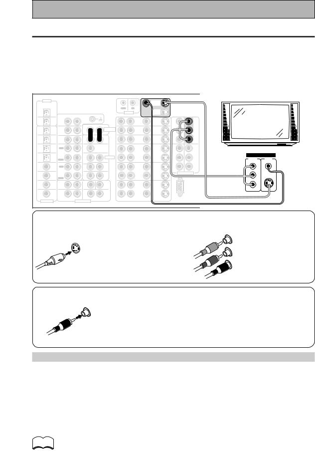
Connecting Your Equipment
Connecting your TV
Connect your TV to the jacks as shown below. Hook up with either component video, S video, or composite video cords (the quality descends in this order). If you use component video cables to hook up your DVD player (or other components) then you must hook up your TV with component video cables as well. In general it is easiest to use one kind of video cord for all your video components (DVD player, TV, satellite TV receiver, etc.) but you can use different kinds of cables (see "Video Converter" below).
Before making or changing the connections, switch off the power and disconnect the power cord from the AC outlet.
|
DIGITAL |
|
|
|
|
|
|
|
MONITOR |
|
|
|
|
· |
Å |
ª |
|
|
|
PCM/2DIGITAL |
|
|
|
|
|
|
|
OUT |
|
|
|
L |
|
|
|
|
|
|
|
/DTS/MPEG |
|
|
|
|
OUT |
IN |
|
|
|
|
|
|
|
|
AC OUTLET |
|
|||
|
2 |
|
|
|
|
|
|
|
MONITOR |
|
|
|
|
|
|
|
|
|
|
|
OUT |
|
|
|
|
|
CONTROL |
|
|
|
|
|
|
|
|
|
|
||
|
|
|
AUDIO L |
|
|
OUT |
|
|
|
FRONT |
|
|
|
|
|
|
|||
|
|
|
R |
|
|
|
|
|
|
|
|
|
|
|
|
|
|
||
|
|
PHONO |
|
|
|
|
|
|
|
|
|
TV/monitor |
|
|
|||||
|
1 |
|
|
|
|
|
DVD |
|
IN |
|
AM LOOP |
R |
|
|
|||||
|
|
|
|
|
|
|
|
|
|
|
|||||||||
|
OUT |
IN |
|
|
|
|
|
IN |
IN |
|
Y |
ANTENNA |
|
|
|||||
|
|
|
|
|
|
/LD |
1 |
|
|
|
|
|
|
||||||
|
|
|
|
|
AUDIO |
|
|
|
|
Y |
MONITOR |
ANTENNA |
|
|
|
|
|
|
|
|
|
|
|
|
|
|
|
|
|
|
|
|
|
|
|
|
|
||
7 |
(CD-R/ |
CD |
|
|
|
POWER AMP |
|
TV |
|
|
OUT |
FM |
|
|
|
|
|
|
|
|
TAPE1 |
IN |
|
|
|
IN |
|
IN |
|
|
|
|
|
|
|
|
|
||
IN |
/MD) |
|
|
|
R |
L |
|
IN |
|
PB |
PB |
75Ω UNBAL |
CENTER |
|
|
|
|
|
|
|
|
|
|
|
|
|
|
|
|
|
|
|
|
||||||
6 |
|
TUNER |
|
|
|
FRONT |
|
SAT |
|
|
|
|
|
|
|
|
|
|
|
|
(VCR2) |
|
|
|
|
|
IN |
|
|
|
|
|
|
|
|
|
|
||
|
IN |
|
|
|
|
|
IN |
|
|
|
|
|
|
|
|
|
|
||
IN |
|
|
|
R |
L |
|
|
PR |
PR |
|
|
|
|
|
|
|
|
||
|
|
|
|
|
|
|
|
|
|
|
|
|
|
|
|||||
5 |
(VCR1 |
OUT |
|
|
CENTER |
|
|
|
|
IN |
IN |
|
L |
|
|
|
|
|
AC |
|
REC |
|
|
|
|
|
OUT |
OUT |
2 |
3 |
|
|
|
|
|
|
|||
|
/DVR) |
CD-R/ |
|
|
|
|
|
|
|
|
|
|
|
|
|
|
|
||
IN |
|
|
|
|
|
|
VCR1 |
|
Y |
Y |
|
SUR- |
|
|
|
|
|
|
|
|
|
TAPE1 |
|
|
|
SUB W. |
|
/DVR |
|
|
|
|
|
VIDEO IN |
|
|
|
||
4 |
|
/MD |
|
|
|
|
|
|
|
|
ROUND |
|
|
|
|
||||
(SAT) |
|
|
|
PRE OUT |
|
IN |
IN |
|
|
|
|
|
|
|
|||||
|
IN |
|
|
|
|
|
|
|
|
|
COMPO- |
VIDEO |
SPEAKERS |
|
|||||
IN |
|
PLAY |
|
|
1 |
2 |
|
|
|
|
|
|
R |
|
|
||||
|
|
|
|
|
|
PB |
PB |
|
|
NENT |
|
|
|||||||
|
|
OUT |
|
|
(Single) |
SUR- |
|
|
|
|
|
|
|
|
|
|
|
|
|
IN 3 |
(CD) |
|
|
|
ROUND |
|
OUT |
OUT |
|
|
|
|
|
Y |
|
ª |
ı |
· |
|
REC |
|
|
R |
L |
|
|
|
|
|
|
|
||||||||
|
|
TAPE2 |
|
|
|
VCR2 |
|
PR |
PR |
|
|
|
|
|
|
|
|
||
|
|
MONITOR |
|
|
|
SUR- |
|
|
|
COMPONENT VIDEO |
|
|
|
(Single) |
|
|
|
|
|
|
|
|
|
|
|
|
|
|
|
L |
|
|
|
|
L |
||||
IN 2 |
(TV) |
IN |
|
|
|
BACK |
|
IN |
IN |
|
|
|
|
|
|
||||
|
|
|
|
|
|
ROUND |
|
|
|
|
|
|
|
|
|
|
|
|
|
|
|
PLAY |
|
|
R |
L (Single) |
|
|
|
|
|
|
SUR- |
|
PB |
S-VIDEO |
|
|
|
|
|
FRONT |
|
|
SUB W. |
CENTER |
|
|
|
|
|
|
ROUND |
|
|
|
|
|
|
IN 1 |
(DVD |
|
|
|
|
|
|
OUT |
OUT |
|
|
|
BACK |
|
|
|
|
|
|
/LD) |
R |
|
L |
|
|
|
|
|
|
R |
|
PR |
|
|
|
R |
|||
|
|
|
|
|
|
|
|
|
|
|
|
|
|
||||||
|
|
|
|
|
|
VCR3 |
|
|
|
|
|
|
|
|
|||||
|
|
SUR- |
|
|
|
SUR- |
|
|
|
|
|
|
|
|
|
|
|||
|
|
|
|
|
|
|
|
|
|
|
|
|
|
|
|
|
|
||
2RF |
(DVD |
ROUND |
|
|
|
ROUND |
|
IN |
IN |
|
|
|
|
|
|
|
|
|
|
|
|
|
|
BACK |
|
|
|
|
|
|
|
|
|
|
|
||||
IN |
/LD) |
|
|
|
|
|
|
|
|
|
|
|
|
|
|
|
|||
R |
|
L |
R |
L (Single) |
|
|
|
|
|
|
|
|
|
|
|
|
|
||
|
(For LD) |
|
|
|
|
|
RS-232C |
|
|
|
|
|
|
|
|
||||
|
|
|
|
|
R |
AUDIO L |
VIDEO |
|
S2 VIDEO |
|
|
|
|
|
|
|
|
||
ASSIGNABLE |
|
|
MULTI CH INPUT |
|
|
|
|
|
|
|
|
|
|
||||||
|
|
|
|
|
|
|
|
|
|
|
|
|
|
|
|
||||
S Video
S VIDEO
S video cables produce clearer picture reproduction by sending separate signals for the luminance and the color. These jacks are labeled by the Japanese designation "S2" on the VSA-AX10 but they are simply S video jacks.
Component video
|
Y |
Green |
P |
|
|
|
B |
Blue |
P |
|
|
|
R |
Red |
|
The color signal of the TV is divided into the luminance (Y) signal and the color (PB and PR) signals and then output. In this way, interference between the signals is avoided.
Composite Video
Composite video cords are the most common or standard video cord but also the lowest quality. The color on the connector is yellow to distinguish it from regular RCA audio cords which have white and red connectors (see p.22). It is important to use a true composite video cord and not an audio cord (though they look exactly the same) because the impedance is different and this will affect the picture quality.
Video Converter
18
En
This unique feature of the VSA-AX10 allows you to hook up your VCR/DVD or any other video player, and/ or your TV tuner with one type of cord to the amplifier while using a different type of cord to hook up the TV to the amplifier. You can hook them up with either component video, S video, or composite video cords (the quality descends in this order). The only restriction here is that if you hook up your DVD player, or other video device, with component video cords (see above), then you must hook up your TV with component video cords as well. The flexibility afforded by the video converter should make connecting all of your equipment easier and perhaps, in some cases, give you higher picture quality. This model is designed for PAL video format. If you use an NTSC source the video converter will not be able to convert from composite video (in the IN jacks) to S video (in the OUT jacks). All other conversions will be ok.
memo If you use component video cords to hook up any of you equipment you must assign those inputs with the "Assigning the Component Video Inputs" procedure. See page 81 to do this.
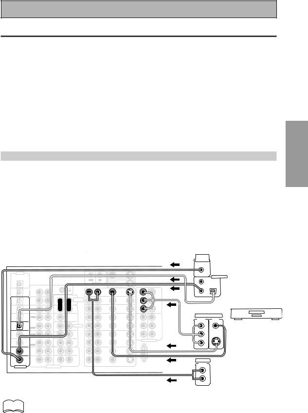
Connecting Your Equipment
Connecting Video Components
Connect your video components to the jacks as shown on the following page. Regarding a DVD there are two types of connections to make, video and audio.
Hook up your video signal with either component video, S video or composite video cords (the quality descends in this order). See "Video Converter" on previous page.
For the audio signal, in order to use digital soundtracks like Dolby Digital, MPEG or DTS you must hook up a digital input, with either a coaxial or optical cord (see p.25). It is also a good idea to hook up your components with analog audio connections as well, since some DVDs may not output a digital audio track. A DVD/LD player or LD player requires a specialized 2RF connection (shown at the very top of the first diagram below) to cover the all possible soundtracks on laser discs.
If you want to record from your DVD player composite (or S video) cord connections and analog audio connections are necessary.
Before making or changing the connections, switch off the power and disconnect the power cord from the AC outlet.
Connecting a DVD, DVD/LD or LD player
Hook up your audio signal with either a coaxial or optical digital cords (you don't need to do both). For DVD/LD or LD players, if your player has a 2RF output hook up the 2 RF connection as well (with a coaxial cord). This will ensure you can use all LDs (see below). If you hook up your DVD/LD player using component video cable connections you might need to setup your DVD player for component video output as well. See your DVD manual for details. If you have a DVD-A or Super Audio CD compatible player, see "Connecting to the Multi Channel Analog Inputs" on page 23.
You need to hook up your audio with analog connections as well.
Before making or changing the connections, switch off the power and disconnect the power cord from the AC outlet.
*The arrows indicate the direction of the signal.
2RF OUT |
LD player only |
(AC-3)(LD) |
R |
L |
R |
(For LD) |
|
|
ASSIGNABLE |
MULTI CH INPUT |
|
L
(Single)
DIGITAL OUT

 (not a PCM-only output)
|
|
DVD/LD player |
|
|
or LD player |
|
|
It is only necessary |
|
|
to make one of the |
|
|
three possible |
EO |
|
VIDEO connections |
|
(see "Video |
|
|
|
|
|
L |
Converter" on p.18). |
R
PREPARATION
memo • If your digital connections are different than the default settings you will need to assign  the digital jacks to the proper component(s) with the "Assigning the Digital Inputs"
procedure. See page 80 to do this.
•If you use component video cords to hook up any of you equipment you must assign those inputs with the "Assigning the Component Video Inputs" procedure. See page 81
to do this. |
19 |
En
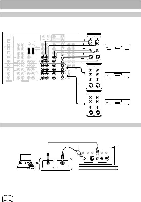
Connecting Your Equipment
Connecting VCRs or DVRs
Connect the video signal with either S video or composite video cords (see p.18). Use analog audio cords for the audio signal. For components you want to record into be sure to hook up both the inputs and outputs and use composite or S video cords for the source players.
|
|
|
|
|
|
|
|
|
|
|
|
|
IN |
|
OUT |
|
ª |
|
|
|
|
DIGITAL |
|
|
|
|
|
|
|
MONITOR |
|
|
|
AUDIO |
|
· |
Å |
|
|
|
|
|
|
|
|
|
|
|
|
|
|
|
|
|
AUDIO |
|
|
|
|
|
||
PCM/2DIGITAL |
|
|
|
|
|
|
|
OUT |
|
|
|
(REC) |
L |
(PLAY) |
|
|
|
|
|
|
/DTS/MPEG |
|
|
|
|
OUT |
IN |
|
|
|
|
|
|
|
|
AC OUTLET |
|
|
|||
|
2 |
|
|
|
|
|
|
|
MONITOR |
|
|
|
L |
|
L |
|
|
|
|
|
|
OUT |
|
|
|
|
|
CONTROL |
|
|
|
|
|
|
|
|
|
||||
|
|
|
AUDIO L |
|
|
OUT |
|
|
|
FRONT |
|
|
|
|
|
|
||||
|
|
|
R |
|
|
|
|
|
|
|
|
|
|
|
|
|
|
|||
|
|
PHONO |
|
|
|
|
|
IN |
|
|
|
|
|
|
|
|
|
|
||
|
1 |
|
|
|
|
|
DVD |
|
|
AM LOOP |
|
R |
|
|
|
|
|
|
||
|
|
|
|
|
|
|
|
|
R |
R |
|
|
|
|
|
|||||
|
OUT |
IN |
|
|
|
|
|
/LD |
IN |
1 |
Y |
ANTENNA |
|
|
|
|
|
|||
|
|
|
|
|
|
AUDIO |
|
IN |
|
Y |
MONITOR |
ANTENNA |
|
|
|
|
|
|
|
|
|
|
|
|
|
|
|
|
|
|
|
|
|
|
|
|
|
|
|
||
7 |
(CD-R/ |
CD |
|
|
|
POWER AMP |
|
TV |
|
|
OUT |
FM |
VIDEO |
|
VIDEO |
|
|
|
|
|
|
TAPE1 |
IN |
|
|
|
IN |
|
IN |
|
|
|
|
|
|
|
|
|
|
||
|
|
|
|
|
IN |
|
|
75Ω UNBAL |
|
|
|
|
|
|
|
|
||||
IN |
/MD) |
|
|
|
R |
L |
|
|
PB |
PB |
CENTER |
|
|
|
|
|
|
|||
|
|
|
|
|
|
|
|
|
|
VCR 1/DVR |
|
|||||||||
6 |
|
TUNER |
|
|
|
FRONT |
|
IN |
|
|
|
|
S-VIDEO |
|
S-VIDEO |
|
|
|||
|
(VCR2) |
IN |
|
|
|
|
|
SAT |
IN |
|
|
|
|
|
|
|
|
|
|
|
|
|
|
R |
L |
|
|
|
PR |
|
|
|
|
|
|
|
|
|
|||
IN |
|
|
|
|
|
|
|
PR |
|
|
|
|
|
|
|
|
|
|||
5 |
(VCR1 |
OUT |
|
|
|
CENTER |
|
|
|
IN |
IN |
|
|
L |
|
|
|
|
AC |
IN |
|
|
|
|
|
OUT |
OUT |
|
|
|
|
|
|
||||||||
|
REC |
|
|
|
|
|
2 |
3 |
|
|
|
|
|
|
||||||
|
/DVR) |
CD-R/ |
|
|
|
|
|
|
|
|
|
|
|
|
|
|
|
|
||
IN |
|
|
|
|
|
|
VCR1 |
|
Y |
Y |
|
SUR- |
|
|
|
|
|
|
|
|
|
|
TAPE1 |
|
|
|
SUB W. |
|
/DVR |
|
|
|
|
|
|
|
|
|
|
|
|
4 |
|
/MD |
|
|
|
|
|
|
|
|
ROUND |
|
|
|
|
|
|
|||
(SAT) |
|
|
|
PRE OUT |
|
IN |
IN |
|
|
|
|
|
|
|
|
|
||||
|
IN |
|
|
|
|
|
|
|
|
|
|
|
SPEAKERS |
|
|
|||||
IN |
|
PLAY |
|
|
1 |
2 |
|
|
|
PB |
PB |
|
|
R |
|
|
|
|
||
|
|
OUT |
|
|
(Single) |
SUR- |
|
|
|
|
|
|
IN |
OUT |
|
|
|
|
|
|
IN 3 |
(CD) |
|
|
|
ROUND |
|
OUT |
OUT |
|
|
|
|
|
ª |
ı |
· |
|
|||
REC |
|
|
|
|
|
|
|
|
AUDIO |
|
AUDIO |
|
|
|||||||
|
|
TAPE2 |
|
|
R |
L |
|
VCR2 |
|
PR |
PR |
|
|
|
|
|
|
|
||
|
|
MONITOR |
|
|
|
SUR- |
|
|
|
COMPONENT VIDEO |
|
(REC) |
|
(PLAY) |
|
|
|
|
|
|
|
|
|
|
|
|
|
|
|
|
L |
(Single) |
|
|
L |
|
|||||
IN 2 |
(TV) |
IN |
|
|
|
BACK |
|
IN |
IN |
|
|
|
|
|
|
|
|
|||
|
|
|
|
|
|
ROUND |
|
|
|
|
|
|
|
|
|
|
|
|
|
|
|
|
PLAY |
|
|
R |
L (Single) |
|
|
|
|
|
|
LSUR- |
|
L |
|
|
|
|
|
|
|
FRONT |
|
|
SUB W. |
CENTER |
|
|
|
|
|
|
ROUND |
|
|
|
|
|
|
|
IN 1 |
(DVD |
|
|
|
|
|
|
OUT |
OUT |
|
|
|
BACK |
|
|
|
|
|
|
|
/LD) |
R |
|
L |
|
|
|
|
|
|
|
R |
|
|
|
|
R |
|
|||
|
|
|
|
|
|
|
|
|
|
R |
R |
|
|
|
|
|||||
|
|
|
|
SUR- |
|
VCR3 |
|
|
|
|
|
|
|
|
||||||
|
|
SUR- |
|
|
|
|
|
|
|
|
|
|
|
|
|
|
|
|
|
|
2RF |
(DVD |
ROUND |
|
|
|
ROUND |
|
IN |
IN |
|
|
|
VIDEO |
|
VIDEO |
|
|
|
|
|
IN |
/LD) |
|
|
|
|
BACK |
|
|
|
|
|
|
|
|
|
|
|
|
||
R |
|
L |
R |
L (Single) |
|
|
|
|
|
|
|
|
|
|
VCR 2 |
|
|
|||
|
(For LD) |
|
|
|
|
|
RS-232C |
|
|
|
|
|
|
|
||||||
|
|
|
|
|
R |
AUDIO L |
VIDEO |
|
S2 VIDEO |
|
|
|
|
|
|
|
||||
ASSIGNABLE |
|
|
MULTI CH INPUT |
|
|
|
|
|
|
|
|
|
|
|
|
|
|
|
||
|
|
|
|
|
|
|
|
|
|
|
|
|
S-VIDEO |
|
S-VIDEO |
|
|
|
|
|
IN |
OUT |
AUDIO |
AUDIO |
(REC) |
(PLAY) |
L |
L |
R |
R |
VIDEO VIDEO
VCR 3
S-VIDEO S-VIDEO
Connecting a Video Component to the Front Panel
Connect a portable DVD player, video game console or any video component to the front panel as show here. Front video connections are accessed via the front panel input selector as "VIDEO."
|
|
|
EFFECT/CH LEVEL |
|
LISTENING |
|
DIGITAL NR |
INPUT ATT |
SELECT |
|
|
CH SELECT |
|
DIGITAL IN |
S-VIDEO |
VIDEO |
L |
AUDIO |
R |
|
|
|
VIDEO INPUT |
|
|
|
|
VIDEO-IN/OUT AUDIO-IN/OUT
Be careful! For portable DVD players you will need a specialized optical cord (for the audio) that has a mini optical plug on one end and a regular optical plug on the other.
memo
You cannot assign the name of the digital input on the front panel. It will always appear as "VIDEO" in the amplifier's display. See page 80 for more information on "Assigning the Digital Inputs".
20
En
Connecting Your Equipment
Connecting Satellite TV (SAT) Components
Hook up the video signal with either component video, S video, or composite video cords (see p.18).
For the audio signal, in order to use digital soundtracks broadcast you must hook up a digital input. Use either a coaxial or optical cable, it doesn't matter which (see p.24-25). We recommend hooking up your audio with analog cables as well (see below).
Before making or changing the connections, switch off the power and disconnect the power cord from the AC outlet.
*The arrows indicate the direction of the TV signal.
|
|
|
|
|
|
|
|
|
|
|
|
|
|
VIDEO |
|
|
|
|
|
|
|
|
DIGITAL |
|
|
|
|
|
|
|
|
|
|
|
COMPO-· |
VIDEO |
ª |
|
|
|
|
|
|
|
|
|
|
|
|
|
|
MONITOR |
|
|
|
NENT |
|
Å |
|
|
|
|
|
|
|
|
|
|
|
|
|
|
|
|
|
|
|
|
OUT |
|
|
|
|
|
|
||
PCM/2DIGITAL |
|
|
|
|
|
|
|
OUT |
|
|
|
L |
|
|
|
|
|
|
|
|
|
|
/DTS/MPEG |
|
|
|
|
OUT |
IN |
|
|
|
|
Y |
|
|
AC OUTLET |
|
|
|
PREPARATION |
||
|
2 |
|
|
|
|
|
|
|
MONITOR |
|
|
|
|
|
|
|
|
|
|
|
|
|
OUT |
|
|
AUDIO L |
|
|
CONTROL |
OUT |
|
|
|
FRONT |
|
|
|
|
|
|
|
||
|
|
|
R |
|
|
|
|
|
|
|
|
|
|
|
|
|
|
|
|||
|
|
PHONO |
|
|
|
|
|
|
|
|
|
PB |
S-VIDEO |
|
|
|
|
|
|||
|
1 |
|
|
|
|
|
DVD |
|
IN |
|
AM LOOP |
R |
|
|
|
|
|
||||
|
OUT |
IN |
|
|
|
|
|
/LD |
IN |
1 |
Y |
ANTENNA |
|
|
|
|
|
|
|
||
|
|
|
|
|
|
AUDIO |
|
IN |
|
Y |
MONITOR |
ANTENNA |
|
|
|
|
|
|
|
|
|
7 |
(CD-R/ |
CD |
|
|
|
POWER AMP |
|
TV |
|
|
OUT |
FM |
|
PR |
|
|
|
|
|
|
|
|
TAPE1 |
IN |
|
|
|
IN |
|
IN |
|
|
|
|
|
|
|
|
|
|
|||
IN |
/MD) |
|
|
|
R |
L |
|
IN |
|
PB |
PB |
75Ω UNBAL |
CENTER |
|
|
|
Satellite tuner |
||||
|
|
|
|
|
|
|
|
|
|
|
|||||||||||
6 |
(VCR2) |
TUNER |
|
|
|
FRONT |
|
SAT |
IN |
|
|
|
|
|
|
|
|||||
|
IN |
|
|
|
|
|
|
|
|
|
|
|
|
||||||||
IN |
|
|
|
R |
L |
|
IN |
|
PR |
PR |
|
|
|
|
|
|
|
|
|
||
|
|
|
|
|
|
|
|
|
|
|
|
|
|
|
|
||||||
5 |
(VCR1 |
OUT |
|
|
|
CENTER |
|
|
|
IN |
IN |
|
L |
|
|
|
|
|
AC |
IN |
|
|
REC |
|
|
|
|
|
OUT |
OUT |
2 |
3 |
|
|
DIGITAL |
|
|
||||||
IN |
/DVR) |
CD-R/ |
|
|
|
|
|
VCR1 |
|
Y |
Y |
|
ANALOG |
|
|
|
|
||||
|
|
|
|
|
|
|
|
SURSTEREO- |
DIGITAL |
|
|
|
|
|
|||||||
4 |
|
TAPE1 |
|
|
|
SUB W. |
|
/DVR |
|
|
|
|
|
|
|
|
|
||||
(SAT) |
/MD |
|
|
|
PRE OUT |
|
IN |
IN |
|
|
|
ROUND |
|
|
|
|
|
|
|
||
|
IN |
|
|
|
|
|
|
|
|
|
|
SPEAKERS |
|
|
|
||||||
IN |
|
PLAY |
|
|
1 |
2 |
|
|
|
PB |
PB |
|
R |
L |
|
|
|
|
|||
|
|
OUT |
|
|
(Single) |
SUR- |
|
|
|
|
|
|
|
|
|
|
|
|
|||
IN 3 |
(CD) |
|
|
|
ROUND |
|
OUT |
OUT |
|
|
|
|
|
|
ª |
ı |
· |
|
|
||
REC |
|
|
R |
L |
|
PR |
PR |
|
|
|
|
|
|
||||||||
|
|
TAPE2 |
|
|
|
VCR2 |
|
|
|
R |
|
|
|
|
|
|
|
||||
|
|
MONITOR |
|
|
|
SUR- |
|
|
|
COMPONENT VIDEO |
|
L |
(Single) |
|
|
|
L |
|
|
||
|
|
|
|
|
|
ROUND |
|
|
IN |
|
|
|
|
|
|
|
|
||||
IN 2 |
(TV) |
IN |
|
|
|
BACK |
|
IN |
|
|
|
|
|
|
|
|
|
||||
|
|
PLAY |
|
|
R |
L (Single) |
|
|
|
|
|
|
SUR- |
|
|
|
|
|
|
|
|
|
|
FRONT |
|
|
SUB W. |
CENTER |
|
|
|
|
|
|
ROUND |
|
|
|
|
|
|
|
|
IN 1 |
(DVD |
|
|
|
|
|
|
OUT |
OUT |
|
|
|
BACK |
|
|
|
|
|
|
|
|
/LD) |
R |
|
L |
|
|
|
|
|
|
R |
|
|
|
|
|
R |
|
|
|||
|
|
|
|
|
|
|
|
|
|
|
|
|
|
|
|
|
|||||
|
|
|
|
|
|
VCR3 |
|
|
|
|
|
|
|
|
|
|
|
||||
|
|
SUR- |
|
|
|
SUR- |
|
|
|
|
|
|
|
|
|
|
|
|
|||
2RF |
(DVD |
ROUND |
|
|
|
ROUND |
|
IN |
IN |
|
|
|
|
|
|
|
|
|
|
|
|
IN |
/LD) |
|
|
|
|
BACK |
|
|
|
|
|
|
|
|
|
|
|
|
|
||
R |
|
L |
R |
L (Single) |
|
|
|
|
|
|
|
|
|
|
|
|
|
|
|
||
|
(For LD) |
|
|
|
|
|
RS-232C |
|
|
|
|
|
|
|
|
|
|
||||
|
|
|
|
|
R |
AUDIO L |
VIDEO |
|
S2 VIDEO |
|
|
|
|
|
|
|
|
|
|
||
ASSIGNABLE |
|
|
MULTI CH INPUT |
|
|
|
|
|
|
|
|
|
|
|
|
||||||
|
|
|
|
|
|
|
|
|
|
|
|
|
|
|
|
|
|
||||
VIDEO
COMPO- |
VIDEO |
NENT |
OUT |
Y |
|
PB |
S-VIDEO |
PR |
|
|
TV tuner |
ANALOG |
DIGITAL |
STEREO |
DIGITAL |
L |
|
R |
|
memo • If you use component video cords to hook up any of you equipment you must assign  those inputs with the "Assigning the Component Video Inputs" procedure. See page 81
to do this.
•If your digital connections are different than the default settings you will need to assign the digital jacks to the proper component(s) with the "Assigning the Digital Inputs" procedure. See page 80 to do this.
21
En
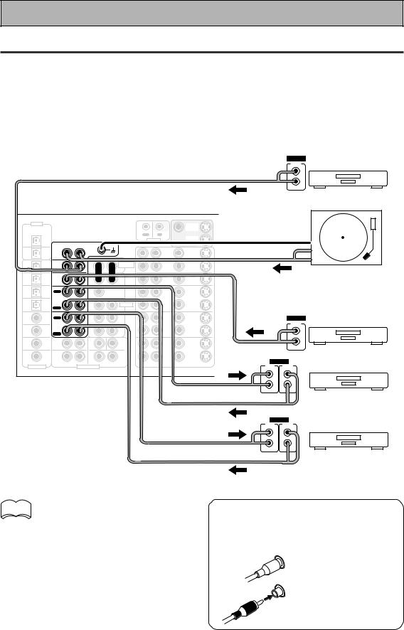
Connecting Your Equipment
Connecting Analog Audio Components
Connect your audio components to the jacks as shown below. These are all analog connections and your analog audio components (turntable, cassette deck) use these jacks. Remember that for components you want to record with you need to hook up four plugs (a set of stereo ins and a set of stereo outs), but for components that only play (like a turntable) you only need to hook up one set of stereo plugs (two plugs). If you want to record to/from digital components (like a CD-R) to/from analog components you must hook up your digital equipment with these analog connections.
Before making or changing the connections, switch off the power and disconnect the power cord from the AC outlet.
*The arrows indicate the direction of the audio signal.
|
|
|
|
|
|
|
|
|
|
OUTPUT |
|
|
|
|
|
|
|
|
|
|
L |
|
|
|
|
|
|
|
|
|
|
R |
|
|
|
|
|
|
|
|
|
|
CD player |
|
DIGITAL |
|
|
|
|
|
|
MONITOR |
|
|
|
|
|
|
|
|
|
|
|
|
|
PCM/2DIGITAL |
|
|
|
|
|
|
OUT |
|
|
|
/DTS/MPEG |
|
|
|
|
OUT |
IN |
|
|
|
|
|
2 |
|
|
|
|
|
|
|
||
|
|
|
|
|
|
|
MONITOR |
|
|
|
|
OUT |
|
|
|
|
CONTROL |
|
|
||
|
|
|
|
|
OUT |
|
|
|||
|
|
|
|
AUDIO L |
|
|
|
|
|
|
|
|
PHONO |
R |
|
|
|
|
|
|
|
|
1 |
|
|
|
|
DVD |
|
|
|
|
|
|
|
|
|
|
IN |
|
|
||
|
OUT |
IN |
|
|
|
|
/LD |
|
|
|
|
|
|
|
|
|
AUDIO |
IN |
|
|
|
7 |
(CD-R/ |
CD |
|
|
|
|
|
|
|
|
|
|
|
POWER AMP |
TV |
|
|
|
|||
|
TAPE1 |
IN |
|
|
|
IN |
IN |
IN |
|
|
IN |
/MD) |
|
|
|
R |
L |
|
|
|
|
|
|
|
|
|
|
Turntable |
||||
(VCR2) |
IN |
|
|
IN |
IN |
|
||||
6 |
|
|
|
FRONT |
|
|||||
|
TUNERCD |
|
|
|
SAT |
|
|
|
||
|
|
|
|
|
|
|
|
|
||
IN |
|
|
|
|
R |
L |
|
|
|
If your turntable has a |
5 |
(VCR1 |
REC |
|
|
|
CENTER |
OUT |
OUT |
|
|
|
OUT |
|
|
|
|
|
|
|
||
|
/DVR) |
TAPE1 |
|
|
|
SUB W. |
/DVR |
|
|
ground wire, connect it to |
IN |
|
CD-R/ |
|
|
|
|
VCR1 |
|
|
|
4 |
|
/MD |
|
|
1 |
2 |
IN |
IN |
|
the SIGNAL GND terminal. |
IN |
|
PLAY |
|
|
|
|||||
|
(SAT) |
IN |
|
|
|
PRE OUT |
|
|
||
|
|
OUT |
|
|
(Single) |
SUR- |
|
|
|
|
|
|
|
|
|
|
|
|
|
||
IN 3 |
(CD) |
|
|
|
ROUND |
OUT |
OUT |
|
|
|
REC |
|
|
|
|
|
|
||||
|
|
TAPE2 |
|
|
R |
L |
VCR2 |
|
|
OUTPUT |
|
|
MONITOR |
|
|
|
SUR- |
|
|
||
IN 2 |
(TV) |
IN |
|
|
|
ROUND |
IN |
IN |
|
|
|
|
|
BACK |
|
L |
|||||
|
|
PLAY |
|
|
R |
L (Single) |
|
|
|
|
|
|
|
|
|
|
|
|
|||
|
(DVD |
FRONT |
|
|
SUB W. |
CENTER |
|
|
|
|
IN 1 |
|
|
|
|
|
OUT |
OUT |
|
R |
|
/LD) |
R |
|
L |
|
|
|
||||
|
|
|
|
|
|
|
|
|||
|
|
|
|
|
VCR3 |
|
|
Tuner |
||
2RF |
(DVD |
SUR- |
|
|
|
BACK |
IN |
|
||
|
|
|
IN |
|
||||||
|
|
|
|
|
SUR- |
|
|
|
|
|
|
|
ROUND |
|
|
|
ROUND |
|
|
|
|
IN |
/LD) |
R |
|
L |
R |
L (Single) |
|
|
|
|
|
(For LD) |
|
|
|
|
|
||||
|
|
|
|
|
R AUDIO L |
VIDEO |
S2 VIDEO |
INPUT |
OUTPUT |
|
ASSIGNABLE |
|
|
MULTI CH INPUT |
|||||||
|
|
|
|
|
(REC) |
(PLAY) |
||||
|
|
|
|
|
|
|
|
|
||
|
|
|
|
|
|
|
|
|
L |
L |
|
|
|
|
|
|
|
|
|
R |
R |
memo Don't hook up any other component to  the PHONO jacks other than a
turntable. It could damage the equipment. If your turntable has a phono pre-amplifier (most do not) please hook it up to an input other than PHONO.
Recorder 1
(CD-R/TAPE/MD)
INPUT |
OUTPUT |
(REC) |
(PLAY) |
L |
L |
R |
R |
Recorder 2
(CD-R/TAPE/MD)
7 Audio cords
Use Phono audio cords (not supplied) to connect the audio components.
L |
Connect red plugs to |
|
R (right) and white |
||
|
||
|
plugs to L (left). |
|
R |
Be sure to insert |
|
completely. |
||
|
22
En
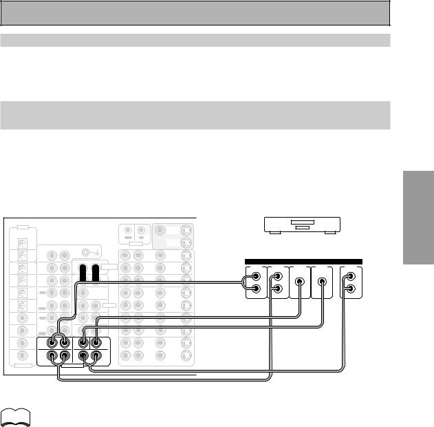
Connecting Your Equipment
Cassette deck placement
Depending on where the cassette deck is placed, during playback of your cassette deck noise may occur which is caused by leakage flux from the transformer in the amplifier. If you experience noise, move the cassette deck farther away from the amplifier.
Connecting to the Multi Channel Analog Inputs (DVD-A or Super Audio
CD compatible player)
If you have a DVD-A or Super Audio CD compatible player, or are using an external Dolby Digital/DTS decoder, connect it to the multichannel analog inputs as shown below. Note that if your DVD-A, Super Audio CD compatible player or decoder which doesn't have surround back outputs, it is possible to create a 6 or 7 channel environment with the "MULTI CH IN SELECT" feature on page 86.
Before making or changing the connections, switch off the power and disconnect the power cord from the AC outlet.
|
DIGITAL |
|
|
|
|
|
|
|
MONITOR |
|
|
|
|
|
PCM/2DIGITAL |
|
|
|
|
|
|
|
OUT |
|
|
|
|
|
|
/DTS/MPEG |
|
|
|
|
|
CONTROL |
OUT |
Components equipped with |
||||||
|
OUT |
|
|
|
|
|
||||||||
|
2 |
|
|
|
|
OUT |
IN |
|
|
|
|
|
|
|
|
|
|
|
|
|
|
|
MONITOR |
|
|
|
|
|
|
|
|
|
|
|
|
|
|
|
|
|
|
|
|
|
|
1 |
PHONO |
R |
AUDIO L |
|
|
|
DVD |
|
7.1 (5.1) channel analog output jack |
||||
|
|
|
|
|
|
|
||||||||
|
OUT |
IN |
|
|
|
|
|
/LD |
IN |
|
|
|
|
|
|
|
|
|
|
|
AUDIO |
|
IN |
|
|
|
ANALOG |
|
|
7 |
(CD-R/ |
CD |
|
|
|
|
|
|
|
|
|
|
||
|
|
|
POWER AMP |
|
TV |
IN |
FRONT |
SURR- |
CENTER |
SUB |
SURR- |
|||
|
TAPE1 |
IN |
|
|
|
IN |
|
|||||||
IN |
/MD) |
|
|
|
R |
L |
|
IN |
|
|
OUND |
|
WOOFER |
OUND BACK |
|
|
|
|
|
|
|
|
|
|
|
|
|||
6 |
(VCR2) |
TUNER |
|
|
|
FRONT |
|
SAT |
IN |
|
L |
L |
|
L |
IN |
IN |
|
|
R |
L |
|
IN |
|
|
|
|
|
||
|
|
|
|
|
|
|
|
|
|
|
|
|||
5 |
(VCR1 |
OUT |
|
|
|
CENTER |
|
OUT |
OUT |
|
R |
R |
|
R |
|
REC |
|
|
|
|
|
|
|
||||||
IN |
/DVR) |
CD-R/ |
|
|
|
|
|
VCR1 |
|
|
|
|
|
|
|
|
|
|
|
|
|
|
|
|
|
|
|||
4 |
|
TAPE1 |
|
|
|
SUB W. |
|
/DVR |
|
|
|
|
|
|
|
/MD |
|
|
|
|
|
|
|
|
|
|
|||
|
(SAT) |
IN |
|
|
|
PRE OUT |
|
IN |
IN |
|
|
|
|
|
IN |
|
PLAY |
|
|
1 |
2 |
|
|
|
|
|
|
|
|
|
|
OUT |
|
|
(Single) |
SUR- |
|
|
|
|
|
|
|
|
IN 3 |
(CD) |
|
|
|
ROUND |
|
OUT |
OUT |
|
|
|
|
|
|
REC |
|
|
|
|
|
|
|
|
|
|
||||
|
|
TAPE2 |
|
|
R |
L |
|
VCR2 |
|
|
|
|
|
|
|
|
MONITOR |
|
|
|
SUR- |
|
|
|
|
|
|
|
|
|
|
|
|
|
|
|
|
|
|
|
|
|
||
|
|
IN |
|
|
|
ROUND |
|
IN |
IN |
|
|
|
|
|
IN 2 |
(TV) |
|
|
|
BACK |
|
|
|
|
|
|
|||
|
|
PLAY |
|
|
R |
L (Single) |
|
|
|
|
|
|
|
|
|
(DVD |
FRONT |
|
|
SUB W. |
CENTER |
|
|
|
|
|
|
|
|
IN 1 |
|
|
|
|
|
|
OUT |
OUT |
|
|
|
|
|
|
/LD) |
R |
|
L |
|
|
|
|
|
|
|
|
|||
|
|
|
|
|
|
|
|
|
|
|
|
|||
|
|
|
|
|
|
VCR3 |
|
|
|
|
|
|
||
|
|
SUR- |
|
|
|
SUR- |
|
|
|
|
|
|
|
|
|
|
|
|
|
|
|
|
|
|
|
|
|
||
2RF |
(DVD |
ROUND |
|
|
|
ROUND |
|
IN |
IN |
|
|
|
|
|
IN |
/LD) |
|
|
|
|
BACK |
|
|
|
|
|
|
||
R |
|
L |
R |
L (Single) |
|
|
|
|
|
|
|
|
||
|
(For LD) |
|
|
|
|
|
|
|
|
|
||||
|
|
|
|
|
R |
AUDIO L |
VIDEO |
|
S2 VIDEO |
|
|
|
|
|
ASSIGNABLE |
|
|
MULTI CH INPUT |
|
|
|
|
|
||||||
|
|
|
|
|
|
|
|
|
|
|
||||
memo If you use only one surround back input hook up the left one.
PREPARATION
23
En
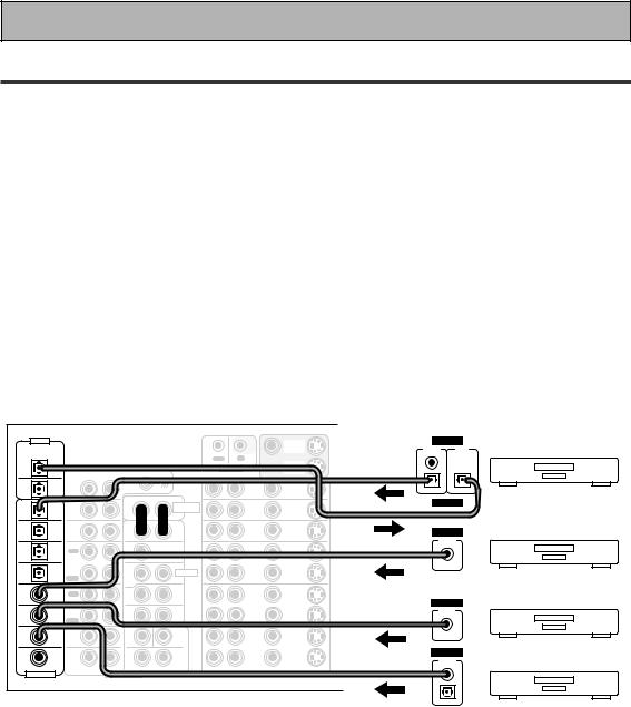
Connecting Your Equipment
Connecting Digital Audio Components
Connect your digital components as shown below. The VSA-AX10 has three coaxial, four optical and one 2RF inputs for a total of eight digital inputs. In order to use digital soundtracks like Dolby Digital, MPEG or DTS (among others) you need to make digital audio connections. You can do this by either a coaxial or an optical connection (you don’t need to do both). The quality of these two types of connections is the same but since some digital components only have one type of digital terminal, it is a matter of matching like with like (for example, the coaxial out from the component to coaxial in on the amplifier). A DVD/LD player or LD player should also be connected to the special 2 RF jack (if the LD has one).
Hook up your digital equipment in accordance with this amplifier's default settings (see next page) unless you want to, or need to, change them. To do this see "Assigning the Digital Inputs" on p.80.
There are two optical digital out jacks (the CD recorder is connected to one in the diagram below). If you connect this to the optical input on a digital recorder (currently these include MD, DAT and CD-R) you can make direct digital recordings with this unit.
We also recommend hooking up your digital components to analog audio jacks (see p.22) in order to make recordings (some digital sources may be protected against making digital copies).
Before making or changing the connections, switch off the power and disconnect the power cord from the AC outlet.
*The arrows indicate the direction of the audio signal.
|
DIGITAL |
|
|
|
|
|
|
MONITOR |
DIGITAL |
|
PCM/2DIGITAL |
|
|
|
|
|
|
OUT |
OUTPUT |
INPUT |
|
|
/DTS/MPEG |
|
|
|
|
|
|
|
(PLAY) |
(REC) |
|
|
|
|
|
OUT |
IN |
|
|
|
|
|
2 |
|
|
|
|
|
|
|
||
|
|
|
|
|
|
|
MONITOR |
|
|
|
|
OUT |
|
|
|
|
CONTROL |
|
|
||
|
|
|
AUDIO L |
|
OUT |
|
|
|||
|
|
PHONO |
R |
|
|
|
|
|
|
|
|
1 |
|
|
|
|
DVD |
|
|
|
|
|
|
|
|
|
|
IN |
|
|
||
|
OUT |
IN |
|
|
|
|
/LD |
|
|
|
|
|
|
|
|
|
AUDIO |
IN |
|
|
|
7 |
(CD-R/ |
CD |
|
|
|
|
|
DIGITAL |
||
|
|
|
POWER AMP |
TV |
|
|||||
|
TAPE1 |
IN |
|
|
|
IN |
IN |
|
|
|
|
|
|
|
IN |
|
|
||||
IN |
/MD) |
|
|
|
R |
L |
|
|
|
|
|
|
|
|
|
|
|
||||
|
|
|
|
|
|
|
|
|||
6 |
(VCR2) |
TUNER |
|
|
|
FRONT |
SAT |
IN |
|
|
|
IN |
|
|
|
|
DIGITAL |
||||
IN |
|
|
R |
L |
IN |
|||||
|
|
|
|
|
|
OUTPUT |
|
|||
5 |
|
|
|
|
|
|
|
|
|
|
(VCR1 |
OUT |
|
|
|
CENTER |
OUT |
OUT |
|
|
|
|
REC |
|
|
|
|
|
|
|||
IN |
/DVR) |
CD-R/ |
|
|
|
|
VCR1 |
|
|
|
|
|
|
|
|
|
|
|
|||
4 |
|
TAPE1 |
|
|
|
SUB W. |
/DVR |
|
|
|
|
/MD |
|
|
|
|
|
|
|||
|
|
|
|
PRE OUT |
IN |
IN |
|
|
||
|
(SAT) |
IN |
|
|
|
|
|
|||
IN |
|
PLAY |
|
|
1 |
2 |
|
|
|
|
|
|
OUT |
|
|
(Single) |
SUR- |
|
|
|
|
IN 3 |
(CD) |
|
|
|
ROUND |
OUT |
OUT |
|
|
|
REC |
|
|
|
|
|
|
||||
|
|
TAPE2 |
|
|
R |
L |
VCR2 |
|
DIGITAL |
|
|
|
MONITOR |
|
|
|
SUR- |
|
|
|
|
|
|
|
|
|
|
|
OUTPUT |
|
||
IN 2 |
(TV) |
IN |
|
|
|
ROUND |
IN |
IN |
|
|
|
|
|
BACK |
|
|
|||||
|
|
PLAY |
|
|
R |
L (Single) |
|
|
|
|
|
(DVD |
FRONT |
|
|
SUB W. |
CENTER |
|
|
|
|
IN 1 |
|
|
|
|
|
OUT |
OUT |
|
|
|
/LD) |
R |
|
L |
|
|
|
|
|||
|
|
|
|
|
|
|
|
|||
|
|
|
|
|
VCR3 |
|
|
|
||
|
|
SUR- |
|
|
|
SUR- |
|
DIGITAL |
||
2RF |
(DVD |
ROUND |
|
|
|
ROUND |
IN |
IN |
||
|
|
|
|
BACK |
|
|
||||
IN |
/LD) |
|
|
|
|
OUTPUT |
|
|||
R |
|
L |
R |
L (Single) |
|
|
|
|||
|
|
|
|
|
|
|
||||
(For LD) |
R AUDIO L |
VIDEO |
S2 VIDEO |
ASSIGNABLE |
MULTI CH INPUT |
|
|
CD recorder
CD player
TV tuner
DVD player
(not a PCM-only output)
24
En
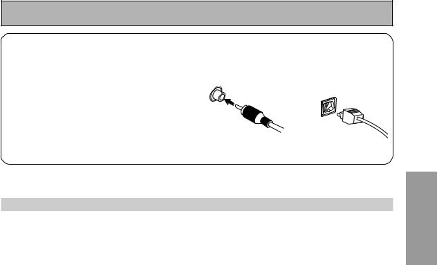
Connecting Your Equipment
7 Coaxial cords/Optical cables
Commercially available digital audio coaxial cords (standard video cords can also be used) or optical cables (not supplied) are used to connect digital components to this amplifier.
Be sure to insert completely and in the case of the optical cable, right-side up. If it is inserted improperly it can break the shutter on the optical terminal (this won't, however, affect the connection or insertion of an optical cable).
Coaxial cord |
Optical cable |
||
(or standard composite |
|
||
video cord) |
|
||
|
|
|
|
Digital Input Default Settings
Unlike analog connections, the jacks for digital connections are not dedicated to one type of component, they can be used freely. Thus you must tell the amplifier what digital component is connected to which jack so your components will be in sync with the names on the remote control buttons and the like. To avoid having to assign the digital inputs you can hook up your equipment in accordance with the amplifier's default settings.
The default settings are:
DIGITAL IN 1 (coaxial): DVD/LD DIGITAL IN 2 (coaxial): TV DIGITAL IN 3 (coaxial): CD DIGITAL IN 4 (optical): SAT DIGITAL IN 5 (optical): VCR1/DVR DIGITAL IN 6 (optical): VCR2
DIGITAL IN 7 (optical): CD-R/TAPE 1/MD 2RF IN (coaxial): DVD/LD
See "Assigning the Digital Inputs" on p.80 if the way you hook up your equipment is different from the default settings.
PREPARATION
25
En
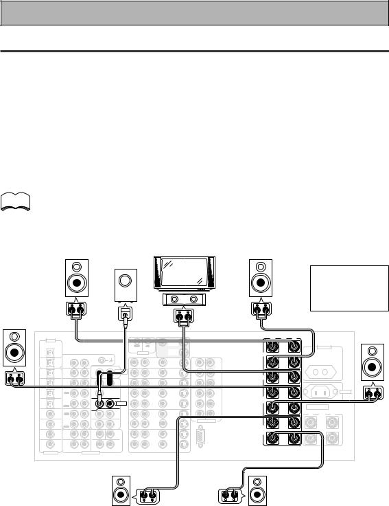
Connecting Your Equipment
Connecting Speakers
We recommend a full complement of seven speakers and a subwoofer as shown here but, naturally, everyone's home setup will vary. Simply connect the speakers you have in the manner described below. The VSA-AX10 will work with just two stereo speakers (called "front" speakers in the diagram) but it is desirable to have at least three speakers (two "front" speakers and a "center" speaker).
One of the latest features of home theater is the use of surround back speakers. These speakers add even greater realism in movie sound effects and some new discs with soundtracks in Dolby Digital, MPEG or DTS incorporate these channels.
In general, make sure you connect the speaker on the right to the R terminal and the speaker on the left to the L terminal. Also make sure the positive and negative (+/–) terminals on the amplifier match those on the speakers.
Before making or changing the connections, switch off the power and disconnect the power cord from the AC outlet.
memo |
• |
If you only have one surround back speaker hook it up to the left surround back terminal. |
|
• |
The VSA-AX10 has two speaker systems, A & B. If you are planning on setting up another |
||
|
|||
|
|
set of speakers (speaker system B), refer to "Speaker System B Setup" on page 67. |
•If you use a THX certified subwoofer use the THX INPUT jack on the subwoofer (if your subwoofer has one) or switch the filter position to THX on your subwoofer.
|
Powered |
|
|
Front |
subwoofer |
Front |
|
TV/monitor |
Use Speakers |
||
speaker |
|
speaker |
|
(Left) |
|
(Right) |
with a nominal |
|
Center |
|
impedance rated |
|
|
6Ω to 16Ω . |
|
|
speaker |
|
Surround |
|
|
|
|
|
INPUT |
|
|
|
|
|
|
|
|
|
|
|
|
speaker |
|
|
|
|
|
|
|
|
|
|
|
|
|
|
|
|
|
Surround |
(Left) |
|
|
|
|
|
|
|
|
|
|
|
|
|
|
|
|
|
|
|
|
|
|
|
|
|
|
|
|
|
|
|
|
|
|
|
|
speaker |
|
DIGITAL |
|
|
|
|
|
|
|
MONITOR |
|
|
· |
Å |
ª |
|
|
|
(Right) |
|
|
|
|
|
|
|
|
|
|
|
|
|
|
|
|
|
||
PCM/2DIGITAL |
|
|
|
|
|
|
|
OUT |
|
|
L |
|
|
|
|
|
|
|
|
/DTS/MPEG |
|
|
|
|
OUT |
IN |
|
|
|
|
|
|
AC OUTLET |
|
|
||
|
2 |
|
|
|
|
|
|
|
MONITOR |
|
|
|
|
|
|
|
|
|
|
OUT |
|
|
|
|
|
CONTROL |
OUT |
|
|
FRONT |
|
|
|
|
|
|
|
|
|
|
R |
AUDIO L |
|
|
|
|
|
|
|
|
|
|
|
|
|
|
|
|
PHONO |
|
|
|
|
|
IN |
|
|
|
|
|
|
|
|
||
|
1 |
|
|
|
|
|
DVD |
|
|
R |
|
|
|
|
|
|
||
|
|
|
|
|
|
|
IN |
Y |
|
|
|
|
|
|
||||
|
OUT |
IN |
|
|
|
|
|
/LD |
1 |
|
|
|
|
|
|
|||
|
|
|
|
|
|
AUDIO |
|
IN |
|
Y |
MONITOR |
|
|
|
|
|
|
|
|
|
|
|
|
|
|
|
|
|
|
|
|
|
|
|
|
||
7 |
(CD-R/ |
CD |
|
|
|
POWER AMP |
|
TV |
|
|
OUT |
|
|
|
|
|
|
|
|
TAPE1 |
IN |
|
|
|
IN |
|
IN |
|
|
|
|
|
|
|
|
|
|
IN |
/MD) |
|
|
|
R |
L |
|
IN |
|
PB |
PB |
CENTER |
|
|
|
|
|
|
|
|
|
|
|
|
|
|
|
|
|
|
|
||||||
6 |
(VCR2) |
TUNER |
|
|
|
FRONT |
|
SAT |
IN |
|
|
|
|
|
|
|
|
|
IN |
IN |
|
|
R |
L |
|
IN |
PR |
PR |
|
|
|
|
|
|
|
||
|
|
|
|
|
|
|
|
|
|
|
|
|
|
|||||
5 |
(VCR1 |
OUT |
|
|
|
CENTER |
|
OUT |
OUT |
IN |
IN |
L |
|
|
|
|
AC |
IN |
|
REC |
|
|
|
|
|
|
|
|
|
||||||||
|
/DVR) |
|
|
|
|
|
|
|
|
2 |
3 |
|
|
|
|
|
|
|
IN |
|
CD-R/ |
|
|
|
|
|
VCR1 |
|
Y |
Y |
SUR- |
|
|
|
|
|
|
|
|
TAPE1 |
|
|
|
SUB W. |
|
/DVR |
|
|
|
|
|
|
|
|
|
|
4 |
|
/MD |
|
|
|
|
|
|
|
ROUND |
|
|
|
|
|
|
||
(SAT) |
|
|
|
PRE OUT |
|
IN |
IN |
|
|
|
|
|
|
|
|
|||
|
IN |
|
|
|
|
|
|
|
|
|
SPEAKERS |
|
|
|||||
IN |
|
PLAY |
|
|
1 |
2 |
|
|
|
PB |
PB |
R |
|
|
|
|
||
|
|
OUT |
|
|
(Single) |
SUR- |
|
|
|
|
|
|
|
|
|
|
|
|
IN 3 |
(CD) |
|
|
|
ROUND |
|
OUT |
OUT |
|
|
|
|
|
ª |
ı |
· |
|
|
REC |
|
|
|
|
|
|
|
|
|
|
|
|||||||
|
|
TAPE2 |
|
|
R |
L |
|
VCR2 |
|
PR |
PR |
|
|
|
|
|
|
|
|
|
MONITOR |
|
|
|
SUR- |
|
|
|
COMPONENT VIDEO |
L |
(Single) |
|
|
|
L |
|
|
IN 2 |
(TV) |
IN |
|
|
|
|
IN |
IN |
|
|
|
|
|
|||||
|
|
|
BACK |
|
|
|
|
|
|
|
||||||||
|
|
|
|
|
|
ROUND |
|
|
|
|
|
|
|
|
|
|
|
|
|
|
PLAY |
|
|
R |
L (Single) |
|
|
|
|
|
SUR- |
|
|
|
|
|
|
|
|
FRONT |
|
|
SUB W. |
CENTER |
|
|
|
|
|
ROUND |
|
|
|
|
|
|
IN 1 |
(DVD |
|
|
|
|
|
|
OUT |
OUT |
|
|
BACK |
|
|
|
|
|
|
/LD) |
|
|
|
|
|
|
|
|
|
|
|
|
|
|
|
|||
|
R |
|
L |
|
|
|
|
|
|
|
R |
|
|
|
|
R |
|
|
|
|
|
|
|
|
VCR3 |
|
|
|
|
|
|
|
|
||||
|
|
SUR- |
|
|
|
SUR- |
|
|
|
|
|
|
|
|
|
|||
2RF |
(DVD |
ROUND |
|
|
|
ROUND |
|
IN |
IN |
|
|
|
|
|
|
|
|
|
IN |
/LD) |
|
|
|
|
BACK |
|
|
|
|
|
|
|
|
|
|
||
|
(For LD) |
R |
|
L |
R |
L (Single) |
|
|
|
|
RS-232C |
|
|
|
|
|
|
|
|
|
|
|
|
R |
AUDIO L |
VIDEO |
|
S2 VIDEO |
|
|
|
|
|
|
|
||
ASSIGNABLE |
|
|
MULTI CH INPUT |
|
|
|
|
|
|
|
|
|
||||||
|
|
|
|
|
|
|
|
|
|
|
|
|
|
|
||||
Surround back |
Surround back |
speaker (Left) |
speaker (Right) |
26
En
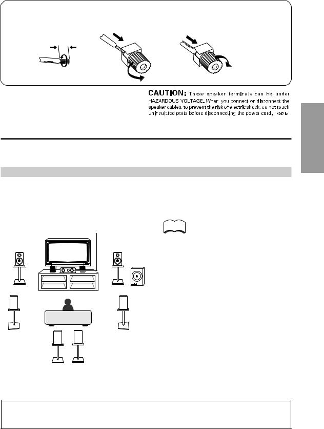
|
|
Connecting Your Equipment |
7 Speaker terminals |
|
|
1 Twist exposed wire |
2 Loosen speaker terminal |
3 Tighten |
strands together. |
and insert exposed wire. |
terminal. |
10mm
Placing Your Speakers
Proper speaker placement is essential to realize the best sound from your system. The diagram and tips given here are just a rough guide, for more information see page 95. Also, it is very important for speaker placement to read the instructions that come with your speakers so please be sure to do so.
Speaker placement
If you have a multiple speaker arrangement the placement of the speakers is extremely important. To achieve the best possible surround sound, install your speakers as shown below. Make sure all speakers are installed securely to prevent accidents and improve sound quality. Be sure to consult p.95 and your speaker manuals for the best placement of the speakers. Some speakers are designed to be floorstanding but others benefit greatly from speaker stands which raise them off the floor.
|
Center Speaker |
memo |
• |
|
|
|
|
Front Speaker |
Front Speaker |
|
|
(L) |
(R) |
|
|
|
Powered |
|
|
|
Subwoofer |
|
|
Surround |
Surround |
|
• |
Speaker (L) |
Speaker (R) |
|
|
•
Surround Back |
Surround Back |
• |
|
Speaker (L) |
Speaker (R) |
||
|
When installing speakers near the TV, we recommend using magnetically shielded speakers to prevent possible interference such as distortion in the color of the TV screen. If you do not have magnetically shielded speakers and notice discoloration of the TV screen, place the speakers farther away from the TV.
Install the center speaker above or below the TV so that the sound of the center channel is localized at the TV screen.
See page 95 for more detailed advice on speaker placement. If you have two surround back
speakers we recommend placing them together and the same distance from your listening position so you can take advantage of the ASA feature. For more details see pages 94-96.
PREPARATION
CAUTION:
When installing the center speaker on top of the TV be sure to secure it with suitable means.
27
En
Connecting Your Equipment
AC Power Cord
Plug in the power cord first to the receiver and then to the wall outlet after you have finished hooking up the rest of your equipment.
CAUTION!
•Do not use any other power cord than the one supplied with this unit.
•The amplifier should be disconnected by removing the mains plug from the wall socket when not in regular use, e.g. when on vacation.
AC Outlet [switched 100 w max]
Power supplied through this outlet is turned on and off by this unit’s STANDBY/ON button. Total electrical power consumption of connected equipment should not exceed 100 W.
CAUTION!
•Do not connect appliances with high power consumption such as heaters, irons, or television sets to the AC OUTLET in order to avoid overheating and fire risk. This can cause the amplifier to malfunction.
•DO NOT CONNECT A MONITOR OR TV SET TO THIS UNIT’S AC OUTLET.
28
En
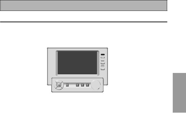
Displays & Controls
Remote Control
These pages describe the buttons on the remote control. Since the screen on this LCD remote control changes when you select a different function, explanations of buttons for controlling other components/functions can be found in the sections for those components/functions.
1 |
2 |
3 |
4 |
5 |
6 |
|
7 |
|
|
|
|
|
|
|
|
|
|
|
|
|
|
use |
lock |
|
|
|
|
|
|
|
|
TV |
|
|
|
|
|
|
REMOTE |
CONTROL |
|
|
|
AMP |
|
|
|
SETUP |
|
|
|
LIGHT |
|
|
|
|
|
|
|
|
|
|
|
|
|
CD |
|
|
|
|
|
|
|
|
|
|
FUNCTION |
|
|
DVD/LD |
|
|
|
CD-R/ |
|
CH + |
|
|
|
|
|
TAPE1 |
|
8 |
||
|
VCR1 |
|
|
|
TUNER |
|
CH – |
|
|
/DVR |
|
|
|
|
|
|
|
|
VCR2 |
|
|
|
VIDEO |
|
VOL + |
|
|
VCR3 |
|
|
|
SAT |
|
VOL – |
|
|
TV |
|
|
|
TV |
|
|
9 |
|
|
|
|
CONTROL |
|
FUNCTION |
||
|
|
|
|
|
MASTER VOLUME |
|
|
|
|
|
MULTI |
SYSTEM |
|
+ |
|
|
|
|
STANDBY/ON |
OPERATION |
OFF |
MUTING |
|
|
|
|
|
ENTER |
|
|
|
|
|
|
|
|
|
|
|
|
– |
|
|
|
|
! |
~ = - |
|
|
0 |
|
||
memo
To turn on the remote control touch it anywhere on the screen
1 STANDBY/ON button |
9 INPUT button |
Press to turn power of the amplifier on or to |
Press to select a source. The button will cycle |
STANDBY (off). |
through all the possible sources. |
2 LIGHT button
Use to turn on and off the backlight on the remote control screen.
3 AMP button
Press to switch the remote control into amplifier mode or to get amplifier screens.
4 Function buttons
These buttons are the basic controls that switch the mode of the amplifier and the remote control, which allows you to control your other components.
5 Remote control screen (see p.30-31)
6 REMOTE SETUP button
Use to customize the remote control functions and the remote control itself. (See “Setting Up Remote Control of Other Components“ starting on p.60)
7 LOCK switch
Use to lock the remote control so it doesn't turn on by accident. For normal use keep it set in USE.
8 TV CONTROL buttons
The following buttons are used to control the TV only and can be used once they are preset to control your TV.
 STANDBY/ON : Press to turn the power of the TV on/off.
INPUT : Press to select the input source for the TV.
CH +/– : Use these buttons to change the channel of the TV.
VOL +/– : Press to control the volume of the TV.
0 MASTER VOLUME button
Use to raise or lower the volume of the amplifier.
- MUTING button
Press to mute or restore the volume.
= SYSTEM OFF button (see p.75)
This button turns off components in two ways. First, when pressed it will turn off all PIONEER components. Secondly, any component that has programmed into the SYSTEM OFF settings will be turned off.
For example : If you programmed power off in the SYSTEM OFF settings for your TV and VCR, pressing the SYSTEM OFF button will turn off these components even if they are not PIONEER products.
~ MULTI OPERATION button
Use this button to start the MULTI OPERATION mode. See p.73 for how to program and use the MULTI OPERATION mode.
! 5˜∞˜2˜3˜ENTER buttons
These buttons can be used for a variety of operations. In the SYSTEM SETUP menu, the 5˜∞ buttons can be used to adjust CHANNEL DELAY or CHANNEL LEVEL.
The 5˜∞ buttons, pressed simultaneously, can be use to lock or unlock a setting (see p.63). These buttons are also used to control the DVD menu for the DVD remote control screen. Also, in TUNER mode they can select station and frequency.
PREPARATION
29
En
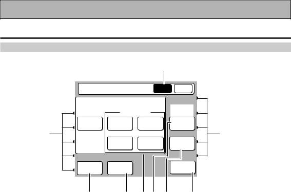
Displays & Controls
Basic Amplifier LCD Screens
Amplifier MAIN Screen
1
Amplifier |
MAIN SUB |
LISTENING MODE
|
SURROUND |
(DVD-A |
||
|
/SACD) |
|||
STEREO |
THX |
STANDARD |
MULTI CH |
|
/DIRECT |
IN |
|||
|
|
|||
8 |
ADVANCED |
ADVANCED |
8 |
|
|
LISTENING |
|||
|
CINEMA |
CONCERT |
CH SEL. |
|
MIDNIGHT |
DIGITAL |
|
ACOUSTIC |
|
NR |
|
CAL. |
||
2 |
3 4 5 6 |
7 |
||
1 Amplifier MAIN button
Press this button to select the MAIN amplifier screen (above) when the remote control is on the SUB amplifier screen.
2 MIDNIGHT button (See p.54)
Switches the MIDNIGHT listening mode on or off (for all modes except THX).
5MULTI CH IN button (See p.56)
Use this button to select the component (for example, a DVD-Audio player) you have hooked up to the MULTI CH INPUT terminals.
6 LISTENING CH SEL. button (See p.47)
Use this button to select a listening channel (5.1, 7.1, or AUTO).
3 DIGITAL NR button (See p.53)
Switches the DIGITAL NR on or off (for all modes except THX).
4LISTENING MODE buttons (See p.49-52)
STEREO/DIRECT: Switches the amplifier into STEREO mode if it was in a different listening mode or toggles between DIRECT and STEREO mode.
THX: Press to put the amplifier into HOME THX listening mode.
STANDARD: Press to put the amplifier into STANDARD listening mode.
ADVANCED CINEMA: Press to put the amplifier into ADVANCED CINEMA listening mode.
ADVANCED CONCERT: Press to put the amplifier into ADVANCED CONCERT listening mode.
7 ACOUSTIC CAL. button (see p.53)
Press to switch on/off the acoustic calibration EQ.
8 DIRECT FUNCTION on/off indicator (See
p.65)
These dots indicate whether the DIRECT FUNCTION is on or off for the function (DVD/LD, CD, etc.) they point to.
30
En
 Loading...