


AUDIO/VIDEO MULTICHANNEL
AMPLIFIER
VSA-E03
Operating Instructions
Thank you for buying this Pioneer product.
Please read through these operating instructions so you will know how to operate your model properly. After you have finished reading the instructions, put them away in a safe place for future reference.
In some countries or regions, the shape of the power plug and power outlet may sometimes differ from that shown in the explanatory drawings. However the method of connecting and operating the unit is the same.
WARNING: TO PREVENT FIRE OR SHOCK HAZARD, DO NOT EXPOSE THIS APPLIANCE TO RAIN OR MOISTURE.
This product complies with the Low Voltage Directive (73/23/EEC), EMC Directives (89/336/EEC, 92/31/EEC) and CE Marking Directive (93/68/EEC).
THE POWER SWITCH IS SECONDARY CONNECTED AND THEREFORE DOES NOT SEPARATE THE UNIT FROM MAINS POWER IN THE STANDBY POSITION.
VENTILATION
ÖWhen installing this unit, make sure to leave space around the unit for ventilation to improve heat radiation (at least 60 cm at top, 10 cm at rear, and 30 cm at each side). If not enough space is provided between the unit and walls or other equipment, heat will build up inside, interfering with performance or causing malfunctions.
ÖDo not place on a thick carpet, bed, sofa or fabric having a thick pile. Do not cover with fabric or other covering.
Anything that blocks ventilation will cause internal temperature to rise, which may lead to breakdown or fire hazard.
IMPORTANT
The lightning flash with arrowhead symbol, within an equilateral triangle, is intended to alert the user to the presence of uninsulated "dangerous voltage" within the product's enclosure that may be of sufficient magnitude to constitute a risk of electric shock to persons.
CAUTION
RISK OF ELECTRIC SHOCK
DO NOT OPEN
CAUTION:
TO PREVENT THE RISK OF ELECTRIC SHOCK, DO NOT REMOVE COVER (OR BACK). NO USER-SER- VICEABLE PARTS INSIDE. REFER SERVICING TO QUALIFIED SERVICE PERSONNEL.
The exclamation point within an equilateral triangle isintendedtoalerttheusertothepresence of important operating and maintenance (servicing) instructions in the literature accompanying the appliance.
Power cord CAUTION!
Handle the power cord by the plug. Do not pull out the plug by tugging the cord and never touch the power cord when your hands are wet as this could cause a short circuit or electric shock. Do not place the unit, a piece of furniture, etc., on the power cord, or pinch the cord. Never make a knot in the cord or tie it with other cords. The power cords should be routed such that they are not likely to be stepped on. A damaged power cord can cause a fire or give you an electrical shock. Check the power cord once in a while. When you find it damaged, ask your nearest PIONEER authorized service center or your dealer for a replacement.
Maintenance of External Surfaces
•Use a polishing cloth or dry cloth to wipe off dust and dirt.
•When the surfaces are dirty, wipe with a soft cloth dipped in some neutral cleanser diluted five or six times with water, and wrung out well, and then wipe again with a dry cloth. Do not use furniture wax or cleaners.
•Never use thinners, benzine, insecticide sprays or other chemicals on or near this unit, since these will corrode the surfaces.
IMPORTANT |
The cut-off plug should be disposed of and must not be |
Do not connect either wire to the earth terminal of a |
||
inserted into any 13 amp socket as this can result in electric |
three pin plug. |
|||
|
|
shock. The plug or adaptor or the distribution panel should |
|
|
FOR USE IN THE UNITED |
be provided with 5 amp fuse. As the colours of the wires in |
NOTE |
||
the mains lead of this appliance may not correspond with |
After replacing or changing a fuse, the fuse cover in the |
|||
KINGDOM |
|
|||
|
coloured markings identifying the terminals in your plug, |
plug must be replaced with a fuse cover which corre- |
||
The wires in this mains lead are coloured in |
proceed as follows: |
sponds to the colour of the insert in the base of the plug |
||
The wire which is coloured blue must be connected to the |
or the word that is embossed on the base of the plug, |
|||
accordance with the following code : |
||||
terminal which is marked with the letter N or coloured black. |
and the appliance must not be used without a fuse cover. |
|||
Blue |
:Neutral |
|||
The wire which is coloured brown must be connected to |
If lost, replacement fuse covers can be obtained from |
|||
Brown |
:live |
|||
the terminal which is marked with the letter L or coloured |
your dealer. |
|||
If the plug provided is unsuitable for your socket |
||||
red. |
Only 5 A fuses approved by B.S.I. or A.S.T.A. to B.S. |
|||
|
|
|||
outlets, the plug must be cut off and a suitable plug |
1362 should be used. |
|
fitted. |
||
|
2
En

Table of Contents
Introductory Information............................................................ |
5 |
Checking the Supplied Accessories .......................................................... |
5 |
How to Use This Manual ........................................................................... |
5 |
Preparing the Remote Control .................................................................. |
5 |
When Making Cable Connections ............................................................. |
6 |
Connections ................................................................................. |
7 |
Audio Components Connections .............................................................. |
7 |
Video Components Connections .............................................................. |
8 |
Digital Connections .................................................................................... |
9 |
DVD 5.1 Channel Connection .................................................................. |
10 |
Speakers ................................................................................................... |
11 |
UP SET
Preparations .............................................................................. |
14 |
Setting Up for Surround Sound .............................................................. |
14 |
Setting Up the Remote Control ............................................................... |
20 |
Clearing the Remote Control Settings .................................................... |
21 |
Names of Parts and Basic Operations..................................... |
22 |
Display ...................................................................................................... |
22 |
Remote Control ........................................................................................ |
23 |
Front Panel ................................................................................................ |
24 |
Sound Modes ............................................................................ |
26 |
Switching ANALOG/DIGITAL Signal Input ............................................. |
27 |
Playback .................................................................................................... |
28 |
Playing Sources with Dolby Digital ........................................................ |
29 |
Selecting a Sound Mode ......................................................................... |
30 |
Listening in MIDNIGHT Listening Mode ................................................ |
31 |
Ajusting bass and treble (tone control) .................................................. |
32 |
Other Operations ...................................................................... |
33 |
Recording from Audio Components ...................................................... |
33 |
Recording from Video Components ....................................................... |
34 |
Remote Controlling Other Components ................................................ |
35 |
Background Control of Other Components ........................................... |
41 |
Additional Information ............................................................. |
42 |
Dolby Digital ............................................................................................. |
42 |
Troubleshooting ....................................................................................... |
43 |
Preset Code List ........................................................................................ |
44 |
Specifications ............................................................................. |
back cover |
OPERATION
3
En

Features
Dolby Digital and Dolby Pro Logic
No need to worry about program formats! When playing Dolby Digital or Dolby Surround software in the 
 (Dolby) Surround mode, decoding switches automatically according to the input signal. All you have to do is sit back and enjoy! (When connecting a DVD/LD player or LD player using the AC-3 RF output, a commercially available RF demodulator (RFD-1) is required.)
Manufactured under license from Dolby Laboratories. “Dolby”, “AC-3”, “Pro Logic”, and double-D symbol are trademarks of Dolby Laboratories. Confidential Unpublished Works. © 1992 - 1997 Dolby Laboratories, Inc. All rights reserved.
Various Surround Effects (DSP)
The DSP (Digital Signal Processing) surround mode allows you to transform your living room into six different sonic environments when listening to music or watching movies.
Midnight Listening Mode
When late night hours or other factors require that the volume be kept low, the surround effects may tend to become less than satisfactory. When the midnight listening mode is on, you can enjoy the effects of quality surround sound even at low volumes.
Optical Digital Output
The digital signal input can be directly output to digital recording components such as MD, DAT and CD-R from the optical digital output jack to create digital recordings.
5.1 Channel Input
By connecting components equipped with 5.1 channel output to the DVD 5.1 channel input on this unit, you can enjoy 5.1 channel surround sound. Connections can be made to a DVD player or Multi channel decoder equipped with 5.1 channel analog output jacks.
5 Channels of Independent Amplification
This receiver incorporates 5 independent 60 watt power amplifiers which enable high quality playback of Dolby Digital sound. This construction provides improved linearity and accurate reproduction of each channel for true high fidelity reproduction from even the most demanding Dolby Digital program sources.
Remote Control of Other Components
The supplied remote control can be used to operate a variety of other components simply by recalling the appropriate preset code.
The Energy-saving Design
This unit is designed to use minimal electricity when power is switched OFF (during Standby). Regarding the value of the power consumption in standby mode, refer to “Specifications” on the back cover.
4
En
Introductory Information
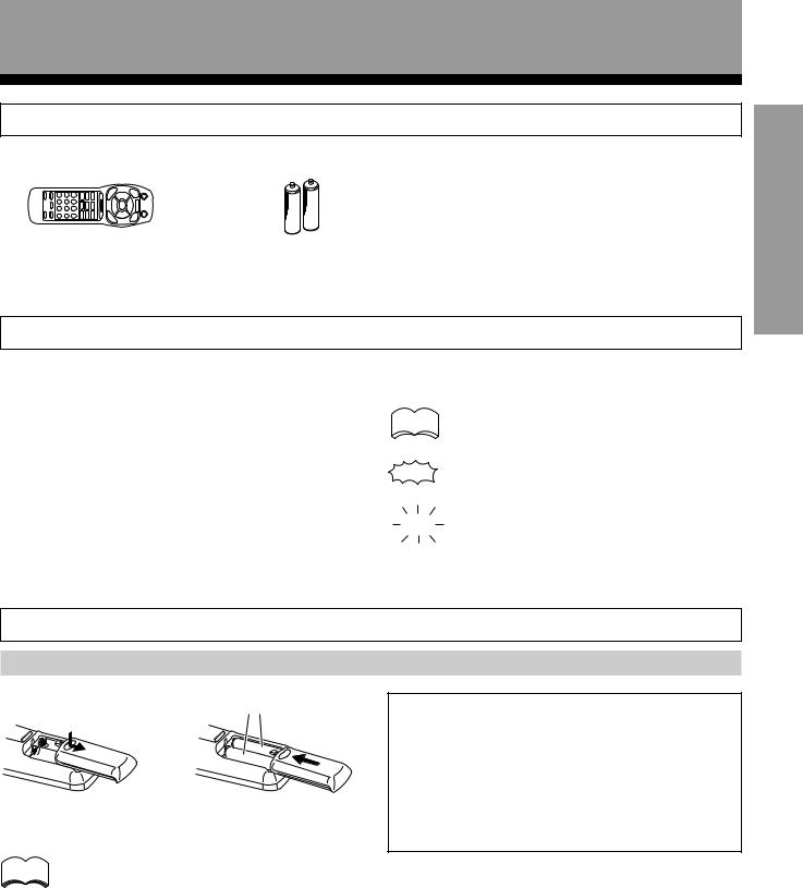
Checking the Supplied Accessories
Please check that you have received all of the following accessories with the amplifier.
Remote control unit |
“AA” IEC LR6 batteries x 2 |
UP SET
How to Use This Manual
This manual is divided into two main sections :
SET UP
This section explains how to make the necessary connections from the amplifier to your other audio and video components. Amplifier operations described later in this section under the heading “Preparations” enable you to set up and customize your home entertainment center.
OPERATION
This section provides complete information about operation of the amplifier and supplied remote control.
The following marks and symbols are used throughout this manual:
memo Provides additional information, precautions,  and advice.
Indicates a blinking button, indicator, or display.
Indicates a steadily lit button, indicator, or display.
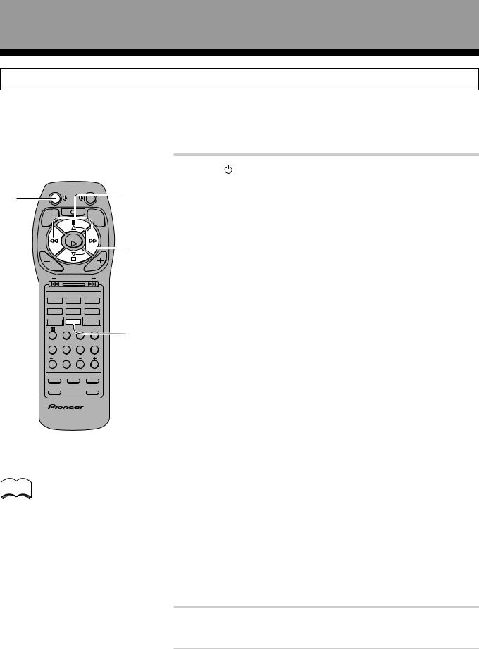
Preparing the Remote Control
Loading the batteries
AA dry cell batteries ((“AA” IEC LR6)×2)
( |
9 |
9 |
\ |
( |
|
When you notice a decrease in the operating range of the remote control, replace all batteries with new ones.
memo |
When changing the batteries, it is |
|
recommended that you load new batteries |
||
|
||
|
within five minutes of removing the old |
|
|
batteries. If not, the preset codes may be |
|
|
canceled and you will need to set them again |
|
|
(refer to page 20). |
CAUTION!
Incorrect use of batteries may result in such hazards as leakage and bursting. Observe the following precautions.
•Never use new and old batteries together.
•Insert the plus and minus sides of the batteries properly according to the marks in the battery case.
•Batteries with the same shape may have different voltages. Do not use different batteries together.
OPERATION
5
En
Introductory Information
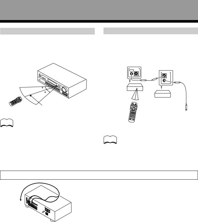
Operating range of remote control unit
Point the remote control toward the remote sensor ë on the front panel of this unit to operate. The remote control unit will operate the amplifier for up to a distance of 7 meters within 30° angle on each side of the sensor of the remote sensor as illustrated below.
30
30
7m
memo
Remote control may not function properly if :
• There are obstacles between the remote control and the remote sensor.
•Direct sunlight or fluorescent light is shining onto the remote sensor.
•The amplifier is located near a device emitting infrared rays.
•Operated simultaneously with another remote control which uses infrared rays.
Operating other PIONEER components
Connecting an optional control cord allows you to operate other PIONEER components simply by pointing the amplifier’s remote control at the remote sensor on the front panel of the amplifier. The amplifier then sends the remote control signals to the other devices via the CONTROL OUT terminal.
CONTROL
OUT IN
CONTROL
IN
OUT
Amplifier
(VSA-E03)
|
PIONEER component |
|
bearing the ë mark. |
|
To CONTROL IN |
|
terminal of another |
Remote Control |
PIONEER component |
bearing the ë mark. |
You can also control PIONEER components memo (and those made by other manufacturers) by
pointing the amplifier’s remote control directly at the respective component. This type of operation does not require control cords. All you have to do is recall the appropriate preset code (Refer to “Recalling preset codes” on page 20).
When Making Cable Connections
Be careful not to arrange cables in a manner that bends the cables over the top of this unit as shown in the illustration. If the cables are brought over this unit, the magnetic field produced by the transformers in this unit may cause a humming noise to come from the speakers.
6
En
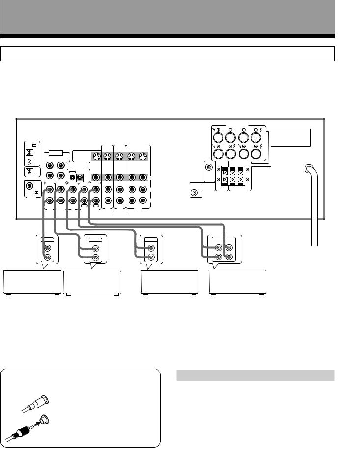
Connections
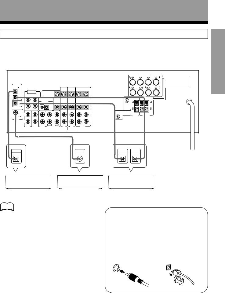
Audio Components Connections
Be sure to switch power to standby and remove the power cord from the wall outlet when you make or change connections.
Connect your audio components as shown below. Refer to “Digital Connections” on page 9 when making digital |
UP SET |
|||||||||||||
connections from your DVD or LD player. |
|
|
|
|
|
|
||||||||
|
|
|
|
|
|
|
|
|
|
|
|
|
|
|
|
|
|
|
|
|
|
|
|
|
|
|
FRONT SPEAKERS |
|
|
|
|
|
|
|
|
|
|
|
|
|
R |
|
L |
|
DIGITAL |
|
|
|
|
|
|
|
|
|
|
|
|
A |
|
|
|
|
|
|
|
|
|
|
|
|
|
|
|
|
IN |
|
|
|
|
|
|
|
|
|
|
|
|
|
|
PCM/ |
|
|
|
|
|
S |
S |
S |
S |
|
|
|
|
|
|
|
|
|
|
|
|
|
|
|
|
||||
OPT |
DVD 5.1 CH |
|
|
|
IN |
IN |
IN |
OUT |
|
|
|
B |
|
|
1 |
|
|
S |
|
|
|
|
|
|
|
|
|||
INPUT |
TO |
|
|
|
|
|
|
|
|
|
||||
|
|
|
|
|
|
|
|
|
|
|||||
|
SURROUND |
MONITOR OUT |
|
|
|
|
|
|
|
|
|
|||
OPT |
L |
SUBWOOFER |
TV |
|
|
|
|
|
|
|
|
|
|
|
2 |
|
|
|
|
|
|
|
|
|
|
|
R |
L |
|
|
|
|
|
|
|
|
|
|
|
|
|
|
||
OPT |
|
|
CONTROL |
|
VIDEO |
|
|
|
|
|
|
|
|
|
|
|
|
OUT IN |
|
OUT |
IN |
IN |
IN |
OUT |
|
|
|
|
|
DIGITAL |
|
|
|
|
|
|
|
|
|
CENTER |
|
|
|
|
|
|
|
|
|
|
|
|
VIDEO |
PREOUT |
|
|
|
|
|
OUT |
|
|
|
|
|
|
|
|
|
|
|
|
||
R |
CENTER |
|
|
|
|
|
|
|
|
|
|
|
|
|
COAX |
|
|
|
|
|
|
|
|
|
|
|
|
||
IN |
IN |
IN |
IN |
OUT |
IN |
IN |
IN |
OUT |
SUB |
|
|
|
|
|
|
|
|
|
|
||||||||||
|
L |
|
|
|
|
|
|
|
L |
WOOFER |
|
|
|
|
|
|
|
|
|
|
|
|
PREOUT |
CENTER |
SURROUND |
|
|||
PCM/ |
|
|
|
|
|
|
|
|
SPEAKER |
|
SPEAKERS |
|
||
|
|
|
|
|
|
|
|
|
|
|
|
|
|
|
DIGITAL |
R |
|
|
|
|
|
|
|
R |
|
|
|
|
|
IN |
|
|
|
|
|
|
|
|
|
|
|
|
||
|
|
|
|
|
|
|
|
|
|
|
|
|
||
|
|
|
PLAY |
REC |
TV/ |
DVD/ |
|
|
|
|
|
|
|
|
|
AUX |
TUNER |
CD |
MD/TAPE |
SAT |
LD |
|
VCR |
|
|
|
|
|
|
|
|
DVD 5.1 CH |
|
|
|
|
|
|
||||||
|
|
|
|
|
|
|
|
|
|
|
|
|
||
|
|
|
|
|
|
|
FRONT |
|
|
|
|
|
|
|
È |
|
È |
|
|
|
|
|
|
|
È |
|
Ç |
|
OPERATION |
|
|
|
|
|
|
|
|
È |
|
|
|
|||
|
OUTPUT |
|
|
|
OUTPUT |
|
|
OUTPUT |
PLAY |
REC |
|
|||
|
|
|
|
|
|
|
|
|||||||
|
|
|
|
|
|
|
|
|
|
|||||
|
L |
|
|
|
L |
|
|
|
L |
|
L |
L |
|
|
|
R |
|
|
|
R |
|
|
|
R |
|
R |
R |
|
|
Other |
|
|
|
|
|
|
|
|
|
|
MD recorder |
|||
|
|
|
Tuner |
|
|
|
CD player |
|
|
|||||
Component |
|
|
|
|
|
or Cassette deck |
|
|||||||
*The arrows indicate the direction of the audio signal.
7 Audio cords
Use audio cords (not supplied) to connect the audio components.
L |
Connect red plugs to R (right) |
|
|
|
and white plugs to L (left). |
R |
Be sure to insert completely. |
|
Cassette deck placement
Depending on where the cassette deck is placed, noise may occur during playback of your cassette deck which is caused by leakage flux from the transformer in the amplifier. If you experience noise, move the cassette deck farther away from the amplifier.
7
En

Connections
Video Components Connections
•When connecting components, the amplifier should be off and the power cord unpluged.
•Connect your video components as shown below. Also, refer to “Digital Connections” on page 9 when making digital connections from your DVD or LD player.
•If your TV monitor or video camera has an S-Video input, clearer picture reproduction is possible by connecting the amplifier to your TV monitor or video camera via the S-Video jack.
TV |
Video deck |
|
monitor
OUTPUT INPUT
V V
L L
INPUT
R R
VIDEO S-VIDEO
|
|
|
|
|
|
È |
|
|
|
Ç |
È |
|
|
|
|
|
|
|
|
|
|
|
|
|
|
FRONT SPEAKERS |
|
|
|
|
|
|
|
|
|
|
|
|
|
R |
L |
DIGITAL |
|
|
|
|
|
|
|
|
|
|
|
|
A |
|
|
|
|
|
|
|
|
|
|
|
|
|
|
IN |
|
|
|
|
|
|
|
|
|
|
|
|
|
PCM/ |
|
|
|
|
|
|
S |
S |
S |
S |
|
|
|
|
|
|
|
|
|
|
|
|
|
||||
OPT |
DVD 5.1 CH |
|
|
|
|
IN |
IN |
IN |
OUT |
|
|
B |
|
1 |
|
|
S |
|
|
|
|
|
|
|
|||
|
INPUT |
TO |
|
|
|
|
|
|
|
|
|||
|
|
|
|
|
|
|
|
|
|
||||
|
SURROUND |
MONITOR OUT |
|
|
|
|
|
|
|
|
|||
OPT |
L |
SUBWOOFER |
TV |
|
|
|
|
|
|
|
|
|
|
2 |
|
|
|
|
|
|
|
|
|
|
|
R |
L |
|
|
|
|
|
|
|
|
|
|
|
|
||
OPT |
|
|
CONTROL |
|
VIDEO |
|
|
|
|
|
|
|
|
|
|
|
OUT |
IN |
|
OUT |
IN |
IN |
IN |
OUT |
|
|
|
DIGITAL |
|
|
|
|
|
|
|
|
|
|
CENTER |
|
|
|
|
|
|
|
|
|
|
|
VIDEO |
PREOUT |
|
|
|
OUT |
|
|
|
|
|
|
|
|
|
|
|
||
R |
CENTER |
|
|
|
|
|
|
|
|
|
|
|
|
COAX |
|
|
|
|
|
|
|
|
|
|
|
||
IN |
IN |
IN |
|
IN |
OUT |
IN |
IN |
IN |
OUT |
SUB |
|
|
|
|
|
|
|
||||||||||
|
L |
|
|
|
|
|
|
|
|
|
WOOFER |
|
|
|
|
|
|
|
|
|
|
|
L |
PREOUT |
CENTER |
SURROUND |
|
PCM/ |
|
|
|
|
|
|
|
|
|
SPEAKER |
SPEAKERS |
||
|
|
|
|
|
|
|
|
|
|
|
|
|
|
DIGITAL |
R |
|
|
|
|
|
|
|
|
R |
|
|
|
IN |
|
|
|
|
|
|
|
|
|
|
|
||
|
|
|
|
|
|
|
|
|
|
|
|
||
|
|
|
|
PLAY |
REC |
TV/ |
DVD/ |
|
|
|
|
|
|
|
AUX |
TUNER |
CD |
|
MD/TAPE |
SAT |
LD |
|
VCR |
|
|
|
|
|
|
|
DVD 5.1 CH |
|
|
|
|
|
|||||
|
|
|
|
|
|
|
|
FRONT |
|
|
|
|
|
7 Front |
|
|
|
|
|
|
|
|
|
È |
|
È |
|
|
VIDEO INPUT |
|
|
|
|
|
OUTPUT |
|
OUTPUT |
||||
|
|
|
|
|
|
|
|
|
|||||
|
|
S-VIDEO VIDEO |
L AUDIO R |
|
|
|
|
|
|
|
|||
|
|
|
|
|
|
|
|
|
|
|
V |
|
V |
|
|
|
|
|
|
|
|
|
|
|
L |
|
L |
Video camera
R |
R |
(etc.) |
|
VIDEO INPUT |
|
L R |
|
TV tuner |
DVD player |
(or satellite tuner) |
(or LD player) |
memo |
When connecting components equipped with |
|
S-video jacks, you can make connections to |
||
|
||
|
this unit using S-video cords (not supplied). |
|
|
However, this unit is not designed to convert |
|
|
the format of the video signal. Therefore, the |
|
|
signal from the S IN cannot be output from |
|
|
the VIDEO OUT and similarly the signal from |
|
|
the VIDEO IN cannot be output from the S |
|
|
OUT. |
8
7 Audio/Video cords
Use audio/video cords (not supplied) to connect the video components and a video cord to connect the TV or monitor.


 VIDEO
VIDEO 
 L
L

 R
R
Connect red plugs to R (right), white plugs to L (left), and the yellow plugs to VIDEO.
Be sure to insert completely.
En
Connections
Digital Connections
Digital components can be connected as shown below. You can select up to three of the following be assigned to the |
||||||||||||
digital inputs on this unit: VCR, DVD/LD, TV/SAT, CD, MD/TAPE. To assign the digital inputs, refer to “Setting Up for |
||||||||||||
Surround Sound” on page 14. |
|
|
|
|
|
|
|
|||||
The digital signal input is output directly to digital recording components from the optical digital output jack. |
||||||||||||
|
|
|
|
|
|
|
|
|
|
|
|
UPSET |
|
|
|
|
|
|
|
|
|
|
|
|
|
|
|
|
|
|
|
|
|
|
|
|
FRONT SPEAKERS |
|
|
|
|
|
|
|
|
|
|
|
|
R |
L |
DIGITAL |
|
|
|
|
|
|
|
|
|
|
|
A |
|
|
|
|
|
|
|
|
|
|
|
|
|
IN |
|
|
|
|
|
|
|
|
|
|
|
|
PCM/ |
|
|
|
|
|
S |
S |
S |
S |
|
|
|
|
|
|
|
|
|
|
|
|
||||
OPT |
DVD 5.1 CH |
|
|
|
IN |
IN |
IN |
OUT |
|
|
B |
|
1 |
|
|
S |
|
|
|
|
|
|
|||
|
INPUT |
TO |
|
|
|
|
|
|
|
|||
|
|
|
|
|
|
|
|
|
||||
|
SURROUND |
MONITOR OUT |
|
|
|
|
|
|
|
|||
OPT |
L |
SUBWOOFER |
TV |
|
|
|
|
|
|
|
|
|
2 |
|
|
|
|
|
|
|
|
|
|
R |
L |
|
|
|
|
|
|
|
|
|
|
|
||
OPT |
|
|
CONTROL |
VIDEO |
|
|
|
|
|
|
|
|
|
|
|
OUT |
IN |
OUT |
IN |
IN |
IN |
OUT |
|
|
|
DIGITAL |
|
|
|
|
|
|
|
|
|
CENTER |
|
|
|
|
|
|
|
|
|
|
VIDEO |
PREOUT |
|
|
|
OUT |
|
|
|
|
|
|
|
|
|
|
||
R |
CENTER |
|
|
|
|
|
|
|
|
|
|
|
COAX |
|
|
|
|
|
|
|
|
|
|
||
IN |
IN |
IN |
IN |
OUT |
IN |
IN |
IN |
OUT |
SUB |
|
|
|
|
|
|
||||||||||
|
|
|
|
|
|
|
|
|
L |
WOOFER |
|
|
|
L |
|
|
|
|
|
|
|
PREOUT |
CENTER |
SURROUND |
|
PCM/ |
|
|
|
|
|
|
|
|
SPEAKER |
SPEAKERS |
||
|
|
|
|
|
|
|
|
|
|
|
|
|
DIGITAL |
R |
|
|
|
|
|
|
|
R |
|
|
|
IN |
|
|
|
|
|
|
|
|
|
|
||
|
|
|
|
|
|
|
|
|
|
|
||
|
|
|
|
PLAY |
REC |
TV/ |
DVD/ |
|
|
|
|
|
|
AUX |
TUNER |
CD |
MD/TAPE |
SAT |
LD |
VCR |
|
|
|
|
|
|
|
DVD 5.1 CH |
|
|
|
|
|
|||||
|
|
|
|
|
|
|
|
|
|
|
|
|
|
|
|
|
|
|
|
FRONT |
|
|
|
|
|
|
|
|
|
|
|
|
|
|
È |
|
|
È |
È |
|
|
|
|
|
È |
|
COAX |
DIGITAL |
DIGITAL |
|
|
DIGITAL |
|
|
|
|
|
|
|
|
||||
OUT |
|
|
|
|
|
|
|
OUT |
IN |
|
OUT |
|
CD player |
DVD player |
memo
When playing LD recorded in Dolby Digital
When connecting a DVD/LD player or LD player using the AC-3 RF output, a commercially available RF demodulator (RFD-1) is required. The RF demodulator changes the RF signal to a digital signal which is then processed by the amplifier through the digital input jacks. For more details, refer to the instruction manual supplied with the RFD-1.
The factory setting for each of the digital inputs is described below.
COAX : DVD
OPT 1 : CD
OPT 2 : MD
MD recorder
7Digital audio cords/Fiber-optic cables
Commercially available digital audio coaxial cords (standard video cords can also be used) or fiber-optic cables (not supplied) are used to connect digital components to this amplifier.
When you use optical digital input or output terminals, pull off the caps and insert the plugs. Be sure to insert completely.
Digital audio cord |
Fiber-Optic cable |
||
(or standard video cord) |
|
||
|
|
|
|
9
En
Connections
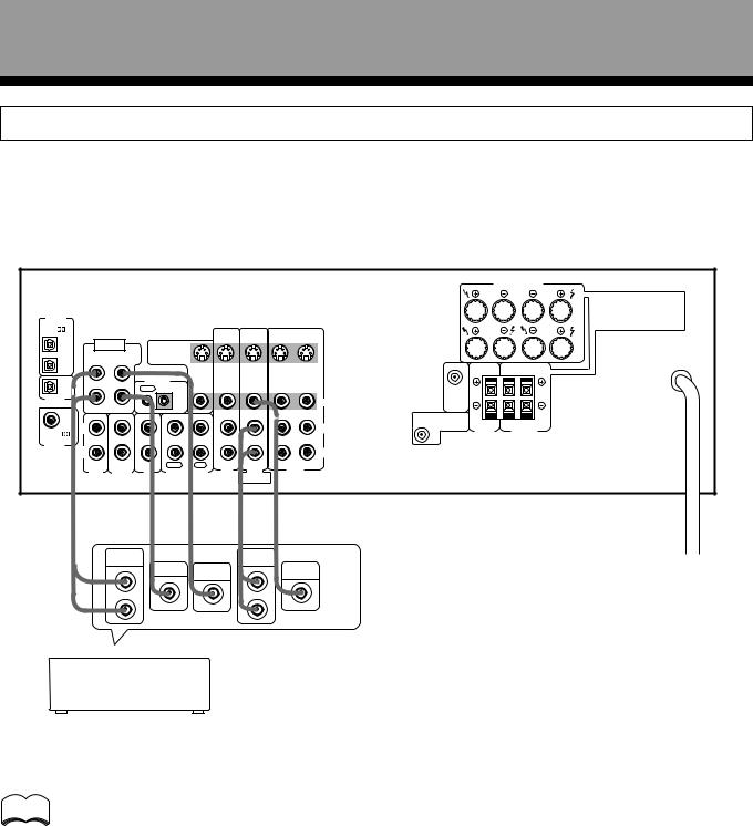
DVD 5.1 Channel Connection
DVD and LD discs are often compatible with both 2 channel and 5.1 channel audio output formats. Refer to page 31 for more information on how to switch between the two input methods.
Connections can be made from a DVD player, or Multi channel decoder equipped with 5.1 analog outputs to the 5.1 analog inputs on this unit.
|
|
|
|
|
|
|
|
|
|
|
FRONT SPEAKERS |
|
|
|
|
|
|
|
|
|
|
|
|
R |
L |
DIGITAL |
|
|
|
|
|
|
|
|
|
|
|
A |
|
|
|
|
|
|
|
|
|
|
|
|
|
IN |
|
|
|
|
|
|
|
|
|
|
|
|
PCM/ |
|
|
|
|
|
S |
S |
S |
S |
|
|
|
|
|
|
|
|
|
|
|
|
||||
OPT |
DVD 5.1 CH |
|
|
|
IN |
IN |
IN |
OUT |
|
|
B |
|
1 |
|
|
S |
|
|
|
|
|
|
|||
|
INPUT |
TO |
|
|
|
|
|
|
|
|||
|
|
|
|
|
|
|
|
|
||||
|
SURROUND |
MONITOR OUT |
|
|
|
|
|
|
|
|||
OPT |
L |
SUBWOOFER |
TV |
|
|
|
|
|
|
|
|
|
2 |
|
|
|
|
|
|
|
|
|
|
R |
L |
|
|
|
|
|
|
|
|
|
|
|
||
OPT |
|
|
CONTROL |
VIDEO |
|
|
|
|
|
|
|
|
|
|
|
OUT |
IN |
OUT |
IN |
IN |
IN |
OUT |
|
|
|
DIGITAL |
|
|
|
|
|
|
|
|
|
CENTER |
|
|
|
|
|
|
|
|
|
|
VIDEO |
PREOUT |
|
|
|
OUT |
|
|
|
|
|
|
|
|
|
|
||
R |
CENTER |
|
|
|
|
|
|
|
|
|
|
|
COAX |
|
|
|
|
|
|
|
|
|
|
||
IN |
IN |
IN |
IN |
OUT |
IN |
IN |
IN |
OUT |
SUB |
|
|
|
|
|
|
||||||||||
|
|
|
|
|
|
|
|
|
L |
WOOFER |
|
|
|
L |
|
|
|
|
|
|
|
PREOUT |
CENTER |
SURROUND |
|
PCM/ |
|
|
|
|
|
|
|
|
SPEAKER |
SPEAKERS |
||
|
|
|
|
|
|
|
|
|
|
|
|
|
DIGITAL |
R |
|
|
|
|
|
|
|
R |
|
|
|
IN |
|
|
|
|
|
|
|
|
|
|
||
|
|
|
|
|
|
|
|
|
|
|
||
|
|
|
|
PLAY |
REC |
TV/ |
DVD/ |
|
|
|
|
|
|
AUX |
TUNER |
CD |
MD/TAPE |
SAT |
LD |
|
VCR |
|
|
|
|
|
|
DVD 5.1 CH |
|
|
|
|
|
|||||
|
|
|
|
|
|
|
|
|
|
|
|
|
|
|
|
|
|
|
|
FRONT |
|
|
|
|
|
|
È |
|
|
È |
È |
|
È |
È |
|
|
|
|
|
|
SURROUND |
|
|
|
|
FRONT |
|
|
|
|
|
|
|
OUTPUT |
CENTER |
SUB |
|
OUTPUT |
|
VIDEO |
|
|
|
|
|
|
|
|
|
|
|
|
|
||||
|
|
|
|
|
WOOFER |
|
|
OUT |
|
|
|
|
|
|
L |
|
|
|
|
|
L |
|
|
|
|
|
|
R |
|
|
|
|
|
R |
|
|
|
|
Components equipped with 5.1 channel analogue output jacks
memo
The 5.1 channel input can only be used when DVD/LD is selected.
10
En
Connections
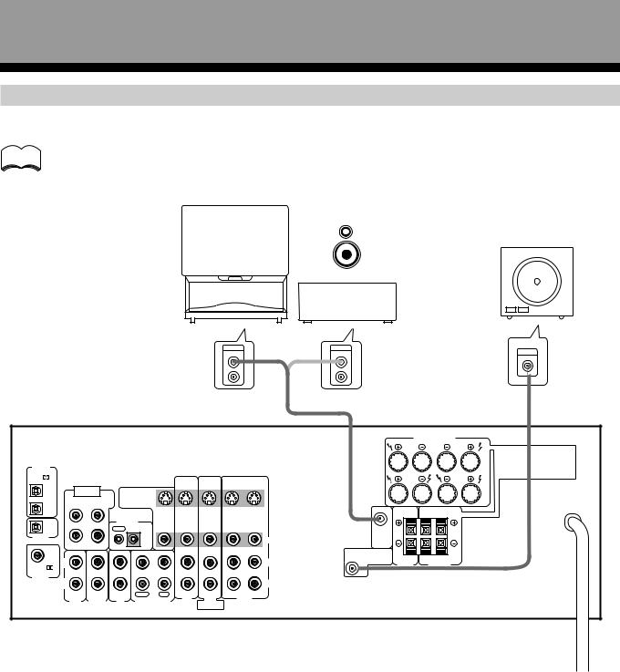
Speakers
• Use speakers with a nominal impedance of 8 Ω to 16 Ω. |
|
|
|
|
|
|
|
|
|
|
|
|||||||||
• The front speaker B terminal is only used in stereo mode (Not available during DVD 5.1 channel, DSP mode, or Dolby |
|
|||||||||||||||||||
Surround mode). |
|
|
|
|
|
|
|
|
|
|
|
|
|
|
|
|
SET |
|||
• When you use the speaker on your TV as a center speaker, please connect the CENTER PREOUT jack on this unit to |
||||||||||||||||||||
|
||||||||||||||||||||
the audio input jack on your TV. In this case, the center speaker shown below is unnecessary. Refer to the instruction |
UP |
|||||||||||||||||||
manual supplied with the TV or monitor you are connecting to for more information. |
|
|
|
|
||||||||||||||||
|
|
|
|
|
||||||||||||||||
• You can set the configuration of your speaker system, whether the sizes of the speakers are large or small, and |
|
|||||||||||||||||||
whether or not you have a sub woofer connected. (Refer to pages 14 to 16) |
|
|
|
|
|
|||||||||||||||
• No sound is output from the front speakers if both A and B speaker systems are selected, but only one pair of |
|
|||||||||||||||||||
speakers is connected to the FRONT SPEAKERS terminals. To select the speaker system, refer to page 24. |
|
|||||||||||||||||||
|
|
|
|
|
|
|
|
|
|
|
|
|
|
|
|
|
|
|||
|
Front Speakers |
Center Speaker |
|
TV |
|
Surround Speakers |
|
|||||||||||||
|
|
(To be used as |
|
|
||||||||||||||||
|
L |
R |
|
C |
|
the center |
|
L |
R |
|
||||||||||
|
|
|
|
|
|
|
|
|
|
speaker) |
|
|
|
|
|
|
||||
|
|
|
|
|
|
|
|
|
|
|
|
|
|
|||||||
|
|
|
|
|
|
|
|
|
|
|
|
|
|
|
|
|
|
|
|
|
|
|
|
|
|
|
|
|
|
|
|
|
|
|
|
|
|
|
|
|
|
|
|
|
|
|
|
|
|
|
|
|
|
|
|
|
|
|
|
|
|
|
|
|
|
|
|
|
|
|
|
|
|
|
|
|
|
|
|
|
|
|
|
|
|
|
|
|
|
|
|
|
|
|
|
|
|
|
|
|
|
|
|
|
(To the audio input)
|
|
|
|
|
|
|
|
|
|
|
|
FRONT SPEAKERS |
|
|
|
|
|
|
|
|
|
|
|
|
|
R |
L |
DIGITAL |
|
|
|
|
|
|
|
|
|
|
|
|
A |
|
|
|
|
|
|
|
|
|
|
|
|
|
|
IN |
|
|
|
|
|
|
|
|
|
|
|
|
|
PCM/ |
|
|
|
|
|
|
S |
S |
S |
S |
|
|
|
|
|
|
|
|
|
|
|
|
|
||||
OPT |
DVD 5.1 CH |
|
|
|
|
IN |
IN |
IN |
OUT |
|
|
B |
|
1 |
|
|
|
S |
|
|
|
|
|
|
|||
|
INPUT |
TO |
|
|
|
|
|
|
|
|
|||
|
|
|
|
|
|
|
|
|
|
||||
|
SURROUND |
MONITOR |
OUT |
|
|
|
|
|
|
|
|||
OPT |
L |
SUBWOOFER |
TV |
|
|
|
|
|
|
|
|
|
|
2 |
|
|
|
|
|
|
|
|
|
|
|
R |
L |
|
|
|
|
|
|
|
|
|
|
|
|
||
OPT |
|
|
CONTROL |
|
VIDEO |
|
|
|
|
|
|
|
|
|
|
|
OUT |
IN |
|
OUT |
IN |
IN |
IN |
OUT |
|
|
|
DIGITAL |
|
|
|
|
|
|
|
|
|
|
CENTER |
|
|
|
|
|
|
|
|
|
|
|
VIDEO |
PREOUT |
|
|
|
OUT |
|
|
|
|
|
|
|
|
|
|
|
||
R |
CENTER |
|
|
|
|
|
|
|
|
|
|
|
|
COAX |
|
|
|
|
|
|
|
|
|
|
|
||
IN |
IN |
IN |
IN |
OUT |
IN |
IN |
IN |
OUT |
SUB |
|
|
||
|
|
|
|||||||||||
|
L |
|
|
|
|
|
|
|
|
L |
WOOFER |
|
|
|
|
|
|
|
|
|
|
|
PREOUT |
CENTER |
SURROUND |
||
PCM/ |
|
|
|
|
|
|
|
|
|
SPEAKER |
SPEAKERS |
||
DIGITAL |
R |
|
|
|
|
|
|
|
|
R |
|
|
|
IN |
|
|
|
|
|
|
|
|
|
|
|
||
|
|
|
|
|
|
|
|
|
|
|
|
||
|
|
|
|
PLAY |
REC |
TV/ |
DVD/ |
|
|
|
|
|
|
|
AUX |
TUNER |
CD |
|
MD/TAPE |
SAT |
LD |
|
VCR |
|
|
|
|
|
|
|
DVD 5.1 CH |
|
|
|
|
|
|||||
|
|
|
|
|
|
|
|
FRONT |
|
|
|
|
|
Sub Woofer
INPUT
Amplified Sub Woofer
Connection methods that differ from the example shown in this manual may be available. For more details, refer to the instruction manual supplied with the sub woofer.
Be sure to complete all other connections before connecting this unit to the AC power source.
7 Speaker terminals
Push tab to the open position, and
insert the wire. Then, close tab Twist exposed wire firmly to secure the wire in place. strands together.
Turn counter-clockwise to loosen, and insert the wire. Then turn clockwise to tighten.
10 |
mm |
|
11
En
Connections
Connecting additional amplifiers
To use separate amplifiers to power your center speaker, make the connections shown below.
memo |
Do not make simultaneous connections to both the CENTER PREOUT jack and the CENTER SPEAKER |
|||||||||||
terminals. (i.e. Do not connect a separate power amplifier to the CENTER PREOUT jack if you have already |
||||||||||||
|
||||||||||||
|
connected a center speaker to the CENTER SPEAKER terminal.) |
|
||||||||||
|
|
|
|
|
|
|
|
|
|
|
|
|
|
|
|
|
PIONEER |
|
|
|
|
|
Powered |
||
|
|
|
|
projection TV |
|
|
|
|
|
|
||
|
|
|
|
|
|
|
|
|
sub woofer |
|||
|
|
|
|
(for center |
|
|
|
|
|
|
||
|
|
|
|
|
|
|
|
|
|
|||
|
|
|
|
channel) |
|
|
|
|
|
|
||
|
|
|
|
|
|
|
|
|
|
|
|
|
|
|
|
|
|
|
|
|
|
|
|
|
|
|
|
|
|
|
|
|
|
|
|
|
|
|
Amplifier (for center channel)
|
|
|
|
|
|
L-Audio |
AUDIO |
(or) |
AUDIO |
|
INPUT |
||
|
|
|
|
|
|
(MONO) |
IN |
|
IN |
|
|||
|
|
|
|
|
|
|
|
|
|||||
|
|
|
|
|
|
L |
|
L |
|
|
|||
|
|
|
|
|
|
|
|
|
R |
|
R |
|
|
|
|
|
|
|
|
|
|
|
|
|
|
FRONT SPEAKERS |
|
|
|
|
|
|
|
|
|
|
|
|
|
R |
L |
DIGITAL |
|
|
|
|
|
|
|
|
|
|
|
|
A |
|
|
|
|
|
|
|
|
|
|
|
|
|
|
IN |
|
|
|
|
|
|
|
|
|
|
|
|
|
PCM/ |
|
|
|
|
|
|
S |
S |
S |
S |
|
|
|
|
|
|
|
|
|
|
|
|
|
||||
OPT |
DVD 5.1 CH |
|
|
|
|
IN |
IN |
IN |
OUT |
|
|
B |
|
1 |
|
|
|
S |
|
|
|
|
|
|
|||
|
INPUT |
TO |
|
|
|
|
|
|
|
|
|||
|
|
|
|
|
|
|
|
|
|
||||
|
SURROUND |
MONITOR |
OUT |
|
|
|
|
|
|
|
|||
OPT |
L |
SUBWOOFER |
TV |
|
|
|
|
|
|
|
|
|
|
2 |
|
|
|
|
|
|
|
|
|
|
|
R |
L |
|
|
|
|
|
|
|
|
|
|
|
|
||
OPT |
|
|
CONTROL |
|
VIDEO |
|
|
|
|
|
|
|
|
|
|
|
OUT |
IN |
|
OUT |
IN |
IN |
IN |
OUT |
|
|
|
DIGITAL |
|
|
|
|
|
|
|
|
|
|
CENTER |
|
|
|
|
|
|
|
|
|
|
|
VIDEO |
PREOUT |
|
|
|
OUT |
|
|
|
|
|
|
|
|
|
|
|
||
R |
CENTER |
|
|
|
|
|
|
|
|
|
|
|
|
COAX |
|
|
|
|
|
|
|
|
|
|
|
||
IN |
IN |
IN |
IN |
OUT |
IN |
IN |
IN |
OUT |
SUB |
|
|
||
|
|
|
|||||||||||
|
|
|
|
|
|
|
|
|
|
|
WOOFER |
|
|
|
L |
|
|
|
|
|
|
|
|
L |
PREOUT |
CENTER |
SURROUND |
PCM/ |
|
|
|
|
|
|
|
|
|
SPEAKER |
SPEAKERS |
||
|
|
|
|
|
|
|
|
|
|
|
|
|
|
DIGITAL |
R |
|
|
|
|
|
|
|
|
R |
|
|
|
IN |
|
|
|
|
|
|
|
|
|
|
|
||
|
|
|
|
|
|
|
|
|
|
|
|
||
|
|
|
|
PLAY |
REC |
TV/ |
DVD/ |
|
|
|
|
|
|
|
AUX |
TUNER |
CD |
|
MD/TAPE |
SAT |
LD |
VCR |
|
|
|
|
|
|
|
|
DVD 5.1 CH |
|
|
|
|
|
|||||
|
|
|
|
|
|
|
|
|
|
|
|
|
|
|
|
|
|
|
|
|
|
FRONT |
|
|
|
|
|
Be sure to complete all other connections before connecting this unit to the AC power source.
12
En
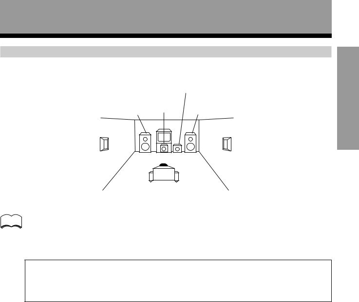
Connections
Speaker placement
To achieve the best possible surround sound, install your speakers as shown below. Be sure all speakers are installed securely to prevent accidents and improve sound quality.
|
Sub Woofer |
||
Front |
Center |
Front |
|
Left |
Right |
||
|
|||
Surround |
Surround |
Left |
Right |
Listening
Position
memo |
• Install the left and right front speakers at equal distances from the TV. |
|
•When installing speakers near the TV, we recommend using magnetically shielded speakers to prevent possible interference such as distortion in the color of the TV screen. If you do not have magnetically shielded speakers and notice discoloration of the TV screen, place the speakers farther away from the TV.
•Install the center speaker above, below the TV so that the sound of the center channel is localized at the TV screen.
CAUTION:
When installing the center speaker on top of the TV, be sure to secure it with tape or some other suitable means.
Otherwise, the speaker may fall from the TV due to external shocks such as earthquakes, and it may lead to endangering those nearby or damaging the speaker.
•If possible, install the surround speakers slightly above ear level.
•It may be difficult to obtain a cohesive surround effect if the surround speakers are installed farther away from the listening position than the front and center speakers.
UP SET
13
En
Preparations
Setting Up for Surround Sound
Be sure to switch the power of this unit on (The STANDBY indicator goes out).
To ensure the best possible surround sound, be sure to complete the following set up operations. This is particularly important when using the 
 (Dolby) Surround mode. You only need to make these settings once (unless you change the placement of your current speaker system or add new speakers, etc.). Refer to the following pages for detailed descriptions of the settings available for each mode.
AMP |
|
TV |
1 |
|
|
MUTING |
|
TV |
FQ |
FUNC |
|
|
+ |
|
ENTER
–
FQ
VOL VOL
CHANNEL
MULTI CONTROL
|
1 |
Press AMP to turn the power on. |
|
3 |
|
The STANDBY indicator goes out. |
|
|
|
||
2 |
Press AMP. |
||
|
|||
|
|
This switches the remote to the surround setup mode. |
|
4 |
|
|
|
3 |
Press ! or Ú to select the mode you desire. |
||
|
|
For best results, start with “SPEAKER setting mode” and make your |
|
|
|
initial adjustments in the order described below. |
The current settings are displayed automatically.
DVD/LD |
TV/SAT |
CD |
|
|
VCR 1 |
TVCONTROL |
TUNER |
|
|
VCR 2 |
AMP |
|
MD/TAPE |
2 |
DSP MODE |
|
MIDNIGHT |
||
1 |
2 |
3 |
4 |
|
CH.SELECT TEST TONE |
ATT |
SIG.SELECT |
|
|
5 |
6 |
7 |
8 |
|
CH.LEVEL |
|
EFFECT |
|
|
9 |
0 |
+10 |
MEMU |
|
|
|
CLASS TV/VCR |
|
|
FUNCTION |
DIRECT |
FL DIMMER |
|
|
MODE CHECK |
|
|
COMMANDER |
|
|
|
SET UP |
|
|
ë
AUDIO/VIDEO PRE-PROGRAMMED
REMOTE CONTROL UNIT
memo
•Press ENTER to exit the setting mode.
•The setting mode is automatically exited if no operation is performed for 20 seconds.
SPEAKER (Front, Center, Surround) setting mode (page 15)
Use to specify the type of speakers you have connected.
SUB WOOFER ON/OFF setting mode (page 16)
Use to specify the sub woofer as on or off.
Crossover frequency setting mode (page 16)
Use to determine which frequencies will be sent to the sub woofer or “Large” speakers.
LFE attenuator setting mode (page 16)
Use to specify the peak level for the LFE channel and the crossover network for rerouted bass frequencies.
Low cut filter ON/OFF setting mode (page 17)
Use to cut the distorted sound from the sub woofer.
FRONT speaker distance setting mode (page 17)
Use to specify the distance from your listening position to your front speaker.
CENTER speaker distance setting mode (page 17)
Use to specify the distance from your listening position to your center speaker.
SURROUND speaker distance setting mode (page 17)
Use to specify the distance from your listening position to your surround speakers.
Dynamic range control setting mode (page 18)
Use to compress the dynamic range of the sound track.
Coaxial digital input setting (page 18)
Use to specify the input to be assigned to the coaxial digital input.
Optical digital input 1 setting (page 18)
Use to specify the input to be assigned to the optical digital input 1.
Optical digital input 2 setting (page 18)
Use to specify the input to be assigned to the optical digital input 2.
4 Press % or Þ to select the setting you desire.
The setting is entered automatically.
5 Repeat steps 3 and 4 to set other surround modes.
14
En

Preparations
SPEAKER setting mode
Establishes the size and configuration of the speaker system you have connected.
In the display, “F”, “C”, and “S” refer to front, center, and surround speakers respectively. Speaker size is denoted as “L” for large speakers, “S” for small speakers, and “ ” (asterisk) if no speaker is connected.
memo |
|
If the cone size of your speaker is larger than 12 cm, please set to Large. |
||||
|
|
|
|
|
|
|
SIGNAL |
|
|
|
SP A |
|
|
SELECT |
|
|
|
|
|
1 Press % or Þ to set the front speaker. |
ANALOG |
|
|
|
|
|
|
|
|
|
|
dB |
|
|
|
|
|
|
|||
|
|
|
|
|||
|
|
|
|
|||
|
|
|||||
|
|
2 |
|
|
Front speaker (initial setting is “L (Large)”) |
|
|
|
|
|
• Select “FL” if your speakers will reproduce bass frequencies effectively or |
||
|
|
|
|
|||
|
|
|
|
|
|
|
|
|
|
|
|
|
if you did not connect a sub woofer. |
|
|
|
|
|
|
• Select “FS” to send bass frequencies to the sub woofer. (The center and |
|
|
|
2 |
|
||
|
|
|
|
surround speakers cannot be set to Large if the front speakers are set to |
||
|
|
|
|
|
|
|
|
|
|
|
|
|
Small. In this case, all bass frequencies are sent to the sub woofer.) |
|
|
|
|
|
|
|
SIGNAL |
|
|
|
SP A |
|
2 Press % or Þ to set the center speaker. |
SELECT |
|
|
|
|
|
|
ANALOG |
|
|
|
|
|
|
|
|
|
|
dB |
|
|
|
|
|
|
|||
|
|
|
|
|||
|
|
|
|
|||
|
|
|||||
Center speaker (initial setting is “L (Large)”)
|
|
2 |
|
|
|
|
|
2 |
|
|
|
|
|
|
|
|
|
|
SP A |
|
SIGNAL |
|||
|
SELECT |
|
|
|
|
ANALOG |
|
|
|


 dB
dB
*Press Ú to advance to the next setting, and press ! to
return to previous setting.
•Select “CL” if your speaker will reproduce bass frequencies effectively.
•Select “CS” to send bass frequencies to the other speakers or sub woofer.
•Select “C ” if you did not connect a center speaker. In this case, the center channel is output from the front speakers.
3 Press % or Þ to set the surround speaker.
Surround speaker (initial setting is “L (Large)”)
•Select “SL” if your speakers will reproduce bass frequencies effectively.
•Select “SS” to send bass frequencies to the other speakers or sub woofer.
•Select “S ” if you did not connect surround speakers. In this case, the sound of the surround channels is output from the front and center speakers.
15
UP SET
En
 Loading...