


Quick Start Guide
Guide rapide
Register your product at
http://www.pioneerelectronics.com (US)
http://www.pioneerelectronics.ca (Canada)
AV Receiver
Récepteur AV
SC-91
English
Thank you for buying this Pioneer product. This Quick Start Guide includes instructions for basic connections and operations to allow simple use of the receiver. For detailed descriptions of the receiver, see the “Operating provided on the included CD-ROM ( ).
).
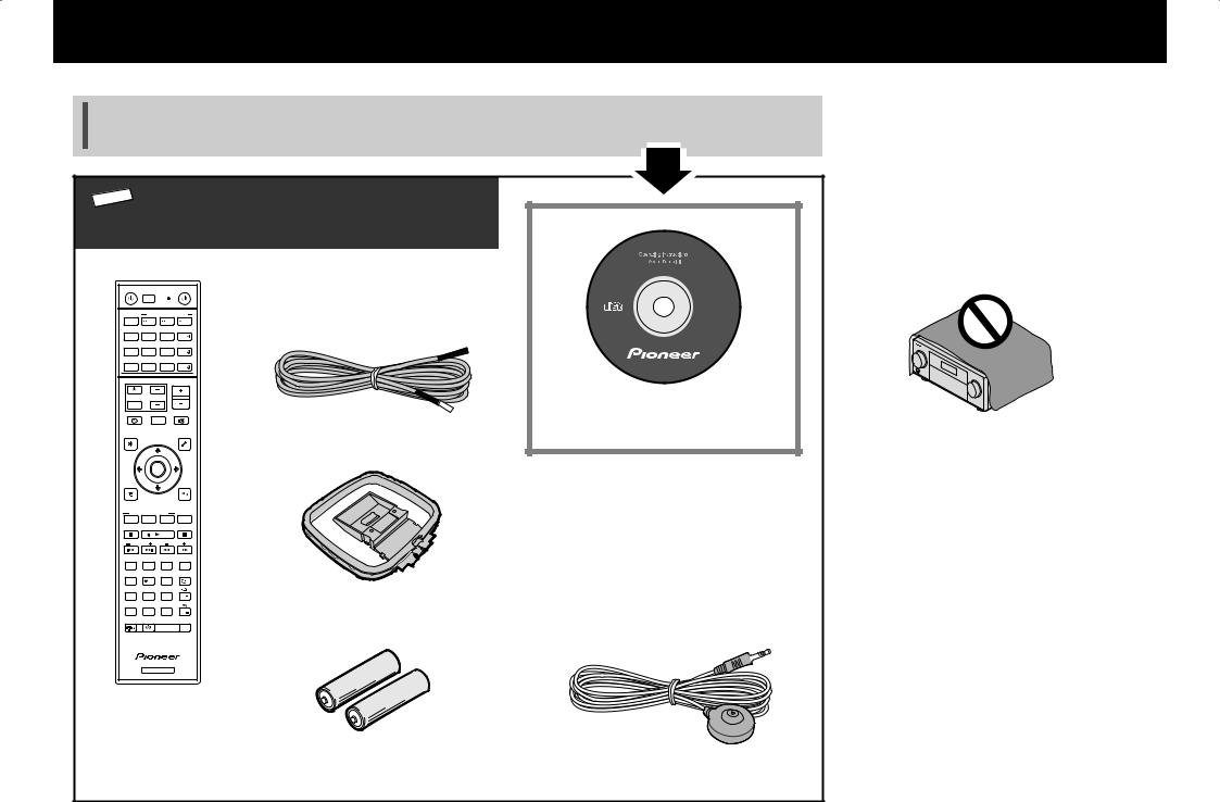
 What’s in the box
STANDBY/ON |
|
|
SOURCE |
Remote Control |
|
ALL ZONE STBY |
|
|
SC-91 |
||
RECEIVER |
SUB ZONE CONTROL |
|
|
||
MAIN |
Z2 |
Z3 |
HDZ |
|
|
|
|
|
HDMI |
|
|
|
|
|
NET |
|
|
|
|
|
ALL |
|
|
|
|
|
VOLUME |
|
|
TV |
VOL |
|
|
|
|
INPUT |
|
|
|
|
CD-ROM |
STATUS |
OUT P. |
MUTE |
|
||
AUDIO P. |
|
|
VIDEO P. |
FM wire antenna |
|
TOP |
|
|
TOOLS |
|
|
MENU |
|
|
MENU |
|
|
|
ENTER |
|
|
|
|
HOME |
|
|
RETURN |
|
|
MENU |
|
|
|
Power cord |
|
|
|
|
|
|
|
LISTENING MODE |
|
|
|
||
AUTO |
SURR |
ADV |
CH LV. |
|
Safety Brochure |
MPX |
BAND |
PTY |
|
||
PRESET |
TUNE |
|
|
||
|
|
|
AUDIO |
|
Warranty sheet |
1 |
2 |
3 |
DISP |
|
|
Fav |
|
|
|||
4 |
5 |
6 |
|
AM loop antenna |
|
D.ACCESS |
|
CLASS |
|
||
7 |
8 |
9 |
CH |
|
These quick start guide |
CLR |
0 |
ENTER |
CH |
|
|
DIMMER SLEEP |
|
RCU SETUP |
|
|
|
|
RECEIVER |
|
|
|
|
AAA size IEC R03 dry cell batteries x2 |
Setup microphone |
VENTILATION CAUTION
When installing this unit, make sure to leave space around the unit for ventilation to improve heat radiation (at least 20 cm at top, 10 cm at rear, and 20 cm at each side).
WARNING
Slots and openings in the cabinet are provided for ventilation to ensure reliable operation of the product, and to protect it from overheating. To prevent fire hazard, the openings should never be blocked or covered with items (such as newspapers, table-cloths, curtains) or by operating the equipment on thick carpet or a bed.
D3-4-2-1-7b*_A1_En
2
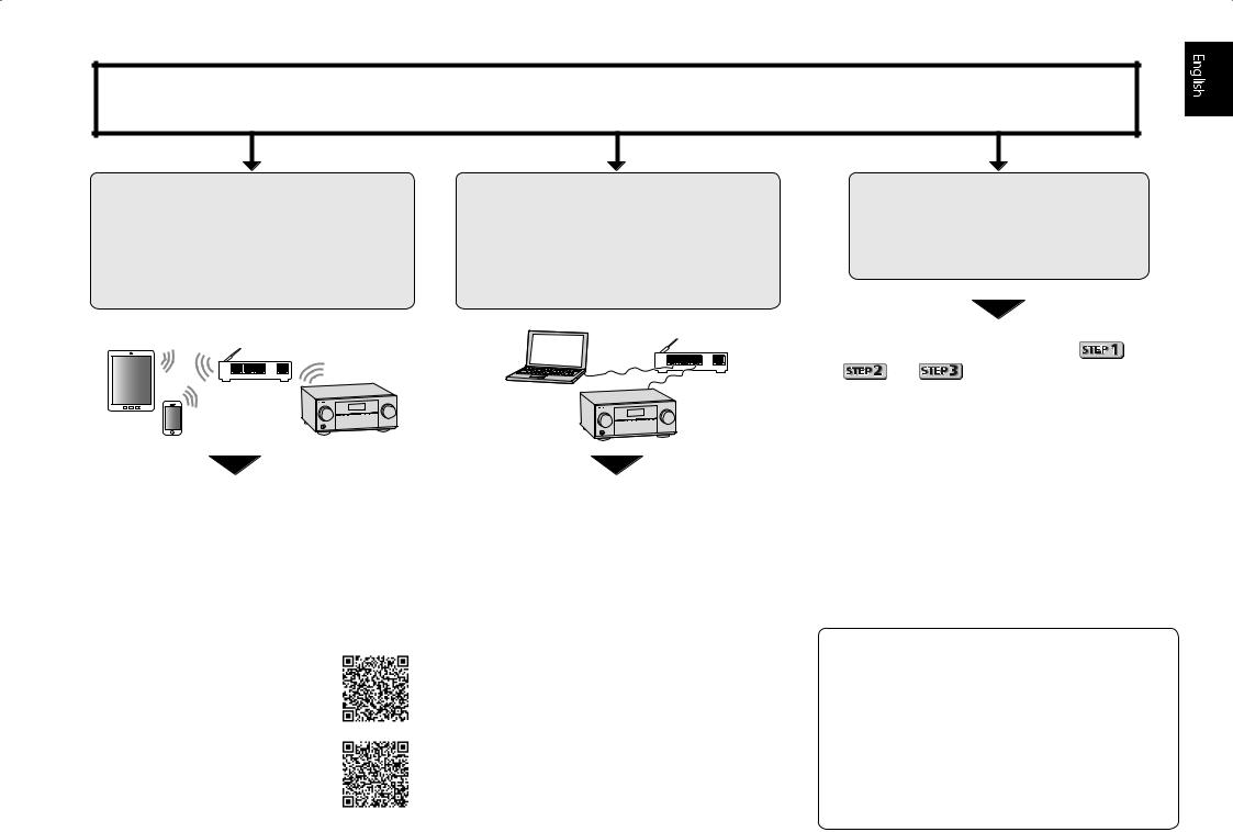
Connection and initial setup
Perform connection and initial settings in any of the ways listed below.
Use “Start-up Navi” app to perform connection and initial settings
•Use a smartphone/tablet.
•Network connection is required.
LAN
1 Download and start “Start-up Navi” app.
2 Proceed along with the app guidance to perform connection and initial settings.
Download “Start-up Navi” app from here.
If you have an iPhone or iPad
Please search for “Start-up Navi” app in the App Store.
If you have an Android device
Please search for “Start-up Navi” app in Google Play.
Follow the guidance of the built-in AVNavigator to perform connection and initial settings
•Use a Mac/PC.
•Network connection is required.
LAN
1 Please read the booklet ”If you have a Mac/ PC”.
2 Follow the guidance of the AVNavigator
built into the receiver to proceed with the connection and initial settings.
Follow the instructions in the booklet to perform connection and initial settings
1 Read the booklet in the order of |
|
|
|
. |
|
2 Follow the instructions of each step to proceed.
Regarding WIRELESS indicator flashing
••Flashes when using WAC Mode. (Mode where network settings can be changed by iPhone, iPad and iPod touch, when this receiver is being used as a Wi-Fi Access point)
When the power is turned on after executing network settings or through wired LAN connection, the WIRELESS indicator will stop blinking.
••When not making a network connection, there is no problem using it as is.
3
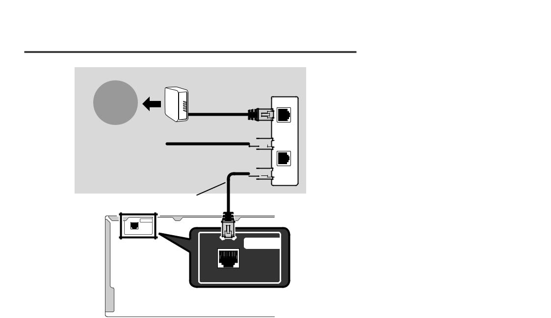
If you have a Mac/PC
Connecting to the network through LAN interface
Internet
|
Modem |
|
Router |
|
WAN |
Computer |
LAN |


 1
1
 2
2 


 3
3
LAN cable (sold separately)
Plugging in the receiver
After connecting to a LAN, connect the power cord of the receiver to a power outlet.
1Plug the supplied power cord into the AC IN socket on the back of the receiver.
2Plug the other end into a power outlet.
Turning the power on
Press STANDBY/ON to switch on the receiver and your computer.
Wait a few minutes after turning the power on before performing the following operation.
 STANDBY/ON
NETWORK
When connecting this receiver to a wireless LAN router by Wi-Fi, refer to the “Basic Setup” → “Setting by referring to the operating instructions” → “Setting network connection” in the CD-ROM’s operating instructions.
4
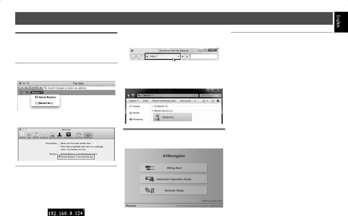
Launching the built-in AVNavigator
Operate AVNavigator by following the screen prompts of your computer. When the WIRELESS indicator is blinking slowly, the AVNavigator cannot be started. Turn this receiver off, connect the LAN cable, and turn it on again.
Using Mac
Launch Safari and click <SC-91> displayed in ‘Bonjour’ on the Bookmarks bar.
••If ‘Bonjour’ is not displayed, tick the ‘Include Bonjour in the Favorites bar’ check box on the ‘Advanced’ tab in the Safari ‘Preferences...’ menu.
Using Windows PC
1 Start up Internet Explorer on your PC (open any random Internet page).
2 Press STATUS on the remote control and check
the front panel display on the receiver (the IP address of the receiver will appear).
(Example Text Display)
If 0.0.0.0, 192.168.1.1 or 169.254.112.202 appears in the address, it indicates that the receiver is not connected to the network. Check to make sure that the receiver and router are properly connected.
3 Enter number in 2 above in the field in
Internet Explorer shown below and then press the ENTER key.
(Example Input Format) 192.168.0.124
••With a Windows PC, you can use the following method to launch AVNavigator.
Launch Explorer and then right-click <SC-91> displayed in the ‘Network’ folder, then click ‘View device webpage’.
About using Wiring Navi
Wiring Navi starts when ‘Wiring Navi’ is pressed on the AVNavigator screen.
••When connection navigation is finished, proceed to
Interactive Operation Guide.
Operating environment
••AVNavigator can be used in the following environments.
––Windows PC: Microsoft® Windows Vista®/Windows® 7/ Windows® 8/Windows® 8.1
––Mac: OS X v 10.9 or 10.8
••Some AVNavigator functions use an Internet browser. The following browsers are supported:
––Windows PC: Internet Explorer® 8, 9, 10, 11 ––Mac OS: Safari 6.0, 7.0
••Depending on the computer network setting or security setting, AVNavigator may not operate.
5
Follow the booklet instructions to perform connection and initial settings
 Connecting up
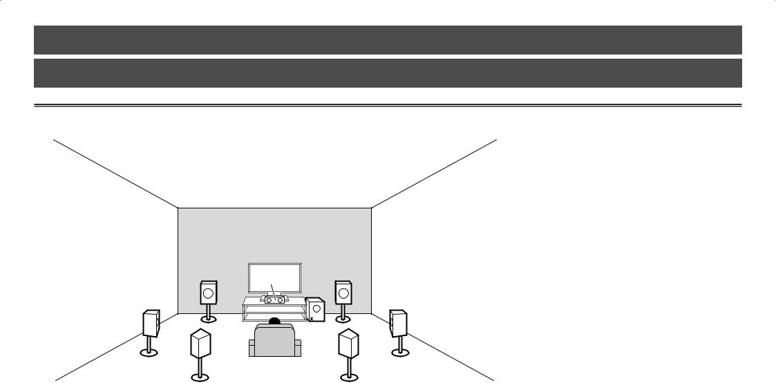
Placing the Speakers
 TMdL TMdR
L |
C |
|
R |
|
|
|
|
SL |
|
SW |
SR |
|
|
|
|
SBL |
|
|
SBR |
L – Front Left C – Center
R – Front Right SL – Surround Left
SR – Surround Right SBL – Surround back Left
SBR – Surround back Right TMdL – Top middle Left TMdR – Top middle Right SW – Subwoofer
 Notes
Notes
••There are also other speaker connection patterns (front wide, etc.). For details, see “Connecting your equipment” of the operating instructions.
••To play Dolby Atmos, you need to connect the speaker of either the Top middle, Surround back, or Front wide.
••When both top middle and surround back are connected, sounds will come out from either one of the speakers according to the listening mode etc.
••The Dolby Enabled Speaker can be used in place of the Top middle speaker. Refer to the operating instructions for details.
6
 Connecting up
|
|
|
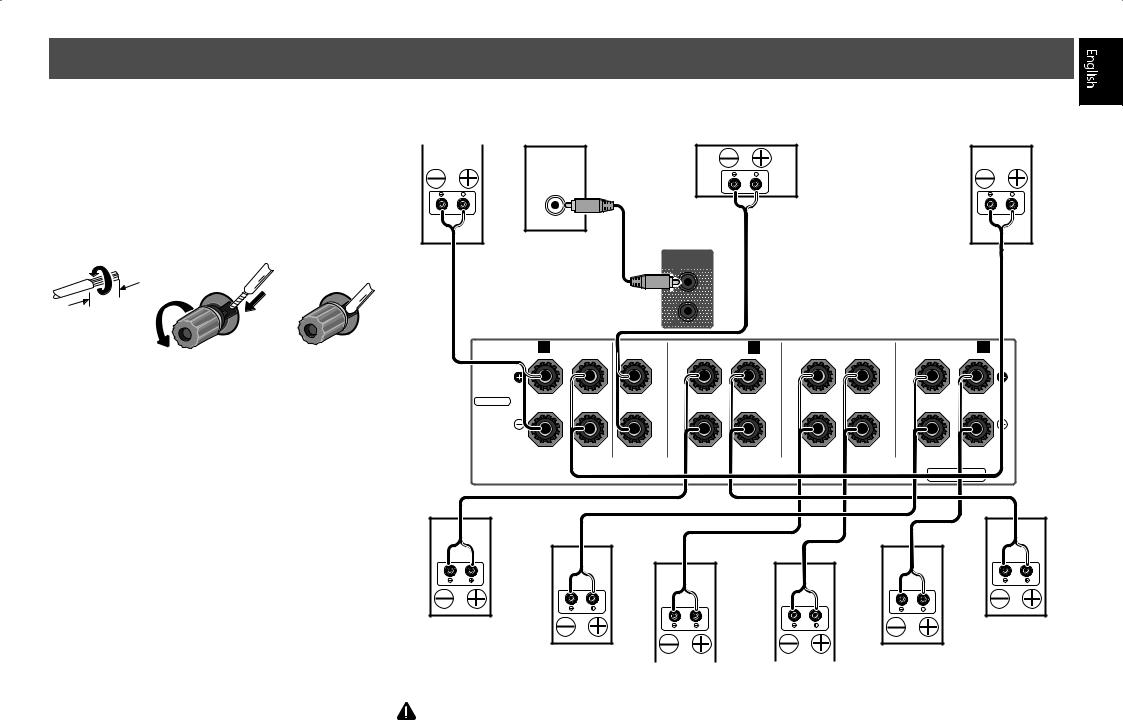
Connecting the speakers |
|
Front Right |
••You can use speakers with a nominal impedance between |
|
(R) |
|
|
|
4 Ω and 16 Ω. |
|
|
Bare wire connections
1 Twist exposed wire strands together.
2Loosen terminal and insert exposed wire.
3Tighten terminal.
1 |
2 |
3 |
10 mm (3/8 in.)
SELECTABLE
Top middle Right (TMdR)
Subwoofer |
Center |
Front Left |
|
(C) |
|||
(SW) |
(L) |
||
|
LINE LEVEL
INPUT
PRE OUT
SUBWOOFER |
1 |
|
|
2 |
R A FRONT |
L CENTER |
RTOP MIDDLE / B L |
|
SURROUND BACK |
|
SURROUND A |
R |
L |
R |
L |
|
(Single) |
|
|
SPEAKERS
Top middle Left (TMdL)
Surround Right |
|
|
|
|
|
|
Surround Left |
(SR) |
Surround back Right |
Surround back Left |
(SL) |
||||
|
|
||||||
|
|
(SBR) |
|
(SBL) |
|
||
CAUTION
••These speaker terminals carry HAZARDOUS LIVE voltage. To prevent the risk of electric shock when connecting or disconnecting the speaker cables, disconnect the power cord before touching any uninsulated parts.
7

 Connecting up
Connecting a TV and playback components
Connecting using HDMI |
|
|
HDMI/DVI-compatible components |
|
|
|
Game console |
DVD player |
Blu-ray Disc player |
Set-top box |
HDD/DVD recorder, |
Blu-ray Disc recorder |
HDMI OUT |
HDMI OUT |
HDMI OUT |
HDMI OUT |
Connecting antennas
a |
b |
c |
FM wire |
|
|
|
antenna |
|
3 |
|
5 |
|
|
ANTENNA |
|
|
|
|
|
AM loop antenna |
|
|
|
|
|
4 |
AMLOOP |
|
|
|
|
1 2
HDMI |
OUT |
|
|
|
|
|
|
|
|
2 |
|
1 |
1 |
|
|
2 |
3 |
4 |
6 /MHL |
|
|
|
|
|
|
|
|
|
|
|
|
(HDZONE) |
|
MAIN |
|
|
|
|
|
|
|
|
|
|
|
|
|
|
|
|
|
|
SELECTABLE |
|
|
(DVD) |
|
( |
) |
(DVR/BDR) |
OUTPUT 5V |
0.9 A MAX) |
|
|
|
AC IN |
|
|
Y |
PB |
PR |
|
|
VIDEO/A |
|
SSIGNABLE 1 |
|
|
|
|
|
|
|
|
|
||||
1 |
MONITOR OUT |
|
|
|
|
|
|
|
|
|
1 (SAT/CBL) |
|
|
||||||||
|
|
|
|
|
|
|
|
|
|
BD IN |
|
|
|
GAME IN |
|
|
|
|
|||
) |
|
|
|
|
|
|
|
|
|
|
|
|
|
|
|
COAXIAL |
|
||||
T/ |
|
|
|
|
|
|
|
|
|
|
|
|
|
|
|
|
|
|
|
|
|
|
|
|
ASSIGNABLE |
|
|
|
|
|
|
DVD IN |
SAT/CBLSUBW |
IN |
|
|
|
1 (TV) |
|
|
|||
COMPONENT VIDEO |
|
|
1 |
ZONE 2 |
SAT/CBL |
DVR/ |
|
|
|
|
PRE OUT |
|
|
|
|
OPTICAL |
|
||||
|
|
|
|
|
|
PRE OUT |
IN |
OUT |
|
|
|
|
1 |
|
|
|
|
|
|
||
|
|
|
|
|
|
|
|
|
|
|
|
|
|
|
|
DIGITAL IN |
|
|
|
||
|
|
|
|
|
|
|
|
|
|
|
L |
|
|
DVR/BDR IN |
ASSIGNABLE |
1 |
OPTICAL |
||||
|
|
|
|
|
|
|
|
|
|
|
|
|
|
|
|
|
|
||||
|
|
|
|
|
|
|
|
|
|
|
R |
|
|
|
|
|
|
|
|
|
IN1 (TV) |
|
|
|
|
|
|
|
|
|
|
|
|
|
|
|
|
|
|
|
|
|
|
|
|
|
|
|
|
|
|
|
|
|
|
|
2 |
|
|
|
|
|
|
|
|
|
RS-232C |
ANTENNA |
|
FM UNBAL 75 |
|
R |
A |
FRONT |
CENTER |
|
R |
TOP MIDDLE / B |
SURROUND BACK |
R |
SURROUND A |
L |
|||||
|
|
|
|
|
|
|
|
L |
|
|
L |
R |
L |
|
|
||||||
|
|
|
|
|
|
|
|
|
|
|
|
|
|
|
|
|
(Single) |
|
|
|
|
|
AM LOOP |
SELECTABLE |
|
|
|
|
|
|
|
1 |
|
IR OUT |
IN |
12V |
|
|
|
TRIGGER |
|
|
|
2 |
|
|
|
(OUTPUT 12V |
SPEAKERS |
CONTROL |
|
TOTAL 150 mA MAX) |
|
|
|
||
You will not be able to view the setting screen from the TV unless this cable is connected.
A
HDMI IN |
OPTICAL |
|
DIGITAL AUDIO OUT |
||
|
HDMI/DVI-compatible TV
|
••If the TV supports the HDMI Audio Return Channel function, the sound of the TV is input to the receiver via the HDMI |
|
terminal, so there is no need to connect an optical digital cable ( A ). In this case, set ARC at HDMI Setup to ON. For details, |
|
see “HDMI Setup” of the operating instructions. |
8 |
••Please refer to the TV’s operation manual for directions on connections and setup for the TV. |
Plugging in the receiver
Only plug in after you have connected all your components to this receiver, including the speakers.
 CAUTION
••Handle the power cord by the plug. Do not pull out the plug by tugging the cord and never touch the power cord when your hands are wet as this could cause a short circuit or electric shock. Do not place the unit, a piece of furniture, etc., on the power cord, or pinch the cord. Never make
a knot in the cord or tie it with other cords. The power cords should be routed such that they are not likely to be stepped on. A damaged power cord can cause a fire or give you an electrical shock. Check the power cord once in a while. When you find it damaged, ask your nearest Pioneer authorized service center or your dealer for a replacement.
••The receiver should be disconnected by removing the mains plug from the wall socket when not in regular use, e.g., when on vacation.
1Plug the supplied power cord into the AC IN socket on the back of the receiver.
2Plug the other end into a power outlet.
 Loading...