


Operating Instructions
PLASMA DISPLAY SYSTEM
IMPORTANT
CAUTION
RISK OF ELECTRIC SHOCK
DO NOT OPEN
The lightning flash with arrowhead symbol, within an |
CAUTION: |
The exclamation point within an equilateral triangle |
||||||||
equilateral triangle, is intended to alert the user to the |
TO PREVENT THE RISK OF ELECTRIC SHOCK, DO |
is intended to alert the user to the presence of |
||||||||
presence of uninsulated “dangerous voltage” within the |
NOT REMOVE COVER (OR BACK). NO USER- |
important operating and maintenance (servicing) |
||||||||
product’s enclosure that may be of sufficient magnitude |
SERVICEABLE PARTS INSIDE. REFER SERVICING |
instructions in the literature accompanying the |
||||||||
to constitute a risk of electric shock to persons. |
TO QUALIFIED SERVICE PERSONNEL. |
appliance. |
||||||||
|
|
|
|
|
|
|
|
|
D3-4-2-1-1_En-A |
|
|
|
|
|
|
|
|
|
|
|
|
|
|
|
|
|
|
|
|
|
|
|
|
|
|
|
|
|
|
|
|
|
|
|
|
|
|
|
|
|
|
|
|
|
1)Read these instructions.
2)Keep these instructions.
3)Heed all warnings.
4)Follow all instructions.
5)Do not use this apparatus near water.
6)Clean only with dry cloth.
7)Do not block any ventilation openings. Install in accordance with the manufacturer’s instructions.
8)Do not install near any heat sources such as radiators, heat registers, stoves, or other apparatus (including amplifiers) that produce heat.
9)Do not defeat the safety purpose of the polarized or grounding-type plug. A polarized plug has two blades with one wider than the other. A grounding type plug has two blades and a third grounding prong. The wide blade or the third prong are provided for your safety. If the provided plug does not fit into your outlet, consult an electrician for replacement of the obsolete outlet.
10)Protect the power cord from being walked on or pinched particularly at plugs, convenience receptacles, and the point where they exit from the apparatus.
11)Only use attachments/accessories specified by the manufacturer.
12)Use only with the cart, stand, tripod, bracket, or table specified by the manufacturer, or sold with the apparatus. When a cart is used, use caution when moving the cart/apparatus combination to avoid injury from tip-over.
13)Unplug this apparatus during lightning storms or when unused for long periods of time.
14)Refer all servicing to qualified service personnel. Servicing is required when the apparatus has been damaged in any way, such as power-supply cord or plug is damaged, liquid has been spilled or objects have fallen into the apparatus, the apparatus has been exposed to rain or moisture, does not operate normally, or has been dropped.
WARNING: This equipment is not waterproof. To prevent a fire or shock hazard, do not place any container filed with liquid near this equipment (such as a vase or flower pot) or expose it to dripping, splashing, rain or moisture.
NOTE TO CATV SYSTEM INSTALLER
THIS REMINDER IS PROVIDED TO CALL THE CATV SYSTEM INSTALLER’S ATTENTION TO ARTICLE 820-40 OF THE NEC THAT PROVIDES GUIDELINES FOR PROPER GROUNDING AND, IN PARTICULAR, SPECIFIES THAT THE CABLE GROUND SHALL BE CONNECTED TO THE GROUNDING SYSTEM OF THE BUILDING, AS CLOSE TO THE POINT OF CABLE ENTRY AS PRACTICAL.
WARNING: This product equipped with a threewire grounding (earthed) plug - a plug that has a third (grounding) pin. This plug only fits a grounding-type power outlet. If you are unable to insert the plug into an outlet, contact a licensed electrician to replace the outlet with a properly grounded one. Do not defeat the safety purpose of the grounding plug
WARNING: To prevent a fire hazard, do not place any naked flame sources (such as a lighted candle) on the equipment.
This digital television is capable of receiving analog basic, digital basic and digital premium cable television programming by direct connection to a cable system providing such programming. A security card provided by your cable operator is required to view encrypted digital programming. Certain advanced and interactive digital cable services such as video-on- demand, a cable operator’s enhanced program guide and data-enhanced television services may require the use of a set-top box. For more information call your local cable operator.
VENTILATION CAUTION:
When installing this unit, make sure to leave space around the unit for ventilation to improve heat radiation. For the minimum space required, see page 17.
WARNING: Slots and openings in the cabinet are provided for ventilation to ensure reliable operation of the product, and to protect it from overheating. To prevent fire hazard, the openings should never be blocked or covered with items (such as newspapers, table-cloths, curtains) or by operating the equipment on thick carpet or a bed.
WARNING: Handling the cord on this product or cords associated with accessories sold with the product will expose you to chemicals listed on proposition 65 known to the State of California and other governmental entities to cause cancer and birth defect or other reproductive harm.
Wash hands after handling. |
D36-P4_A_En |
Information to User
Alteration or modifications carried out without appropriate authorization may invalidate the user’s right to operate the equipment.
[For Canadian model]
This Class B digital apparatus complies with Canadian ICES-003.
FEDERAL COMMUNICATIONS COMMISSION DECLARATION OF CONFORMITY
This device complies with part 15 of the FCC Rules. Operation is subject to the following two conditions: (1) This device may not cause harmful interference, and
(2) this device must accept any interference received, including interference that may cause undesired operation.
Product Name: Plasma Display System
Model Number: PRO-150FD/PRO-110FD
Product Category: Class B Personal Computers & Peripherals
Responsible Party Name: PIONEER ELECTRONICS SERVICE, INC.
Address: 1925 E. DOMINGUEZ ST., LONG BEACH, CA 90801-1760, U.S.A.
Phone: 800-421-1625
URL : http://www.pioneerelectronics.com
NOTE: This equipment has been tested and found to comply with the limits for a Class B digital device, pursuant to Part 15 of the FCC Rules. These limits are designed to provide reasonable protection against harmful interference in a residential installation.
This equipment generates, uses, and can radiate radio frequency energy and, if not installed and used in accordance with the instructions, may cause harmful interference to radio communications. However, there is no guarantee that interference will not occur in a particular installation. If this equipment does cause harmful interference to radio or television reception, which can be determined by turning the equipment off and on, the user is encouraged to try to correct the interference by one or more of the following measures:
–Reorient or relocate the receiving antenna.
–Increase the separation between the equipment and receiver.
–Connect the equipment into an outlet on a circuit different from that to which the receiver is connected.
– Consult the dealer or an experienced radio/TV technician for help.
D8-10-1-2_En
CAUTION: This product satisfies FCC regulations when shielded cables and connectors are used to connect the unit to other equipment. To prevent electromagnetic interference with electric appliances such as radios and televisions, use shielded cables and connectors for connections.
IMPORTANT NOTICE – THE SERIAL NUMBER FOR THIS EQUIPMENT IS LOCATED IN THE REAR.
PLEASE WRITE THIS SERIAL NUMBER ON YOUR ENCLOSED WARRANTY CARD AND KEEP IN A SECURE AREA. THIS IS FOR YOUR SECURITY.
CAUTION: The switch on this unit will not completely shut off all power from the AC outlet. Since the power cord serves as the main disconnect device for the unit, you will need to unplug it from the AC outlet to shut down all power. Therefore, make sure the unit has been installed so that the power cord can be easily unplugged from the AC outlet in case of an accident. To avoid fire hazard, the power cord should also be unplugged from the AC outlet when left unused for a long period of time (for example, when on vacation)
STANDBY: |
When placed into the standby mode, the main power flow is cut and the unit is no longer |
|
fully operational. |
STANDBY/ON Indicator: The indicator is lit red when the unit is in the standby mode and lit blue when it is in the power-on mode. No operation can be performed when the indicator is off. However, the Plasma Display system will still consume some power as long as the power cord is inserted into the power outlet.
Operating Environment
Operating environment temperature and humidity:
+0 ˚C to +40 ˚C (+32 ˚F to +104 ˚F); less than 85 %RH (cooling vents not blocked)
Do not install this unit in a poorly ventilated area, or in locations exposed to high humidity or direct sunlight (or strong artificial light)
D3-4-2-1-7c_A_En

4
En
Contents
Thank you for buying this Pioneer product.
Please read through these operating instructions so you will know how to operate your model properly. After you have finished reading the instructions, put them away in a safe place for future reference.
In some countries or regions, the shape of the power plug and power outlet may sometimes differ from that shown in the explanatory drawings. However the method of connecting and operating the unit is the same.
Illustrations shown in this manual are for the PRO-110FD unless otherwise specified.
Contents |
|
01 Important User Guidance |
|
Information ........................................... |
7 |
02 Safety Precautions .............................. |
10 |
Installation Precautions ............................ |
11 |
03 Supplied Accessories........................... |
12 |
04 Part Names........................................... |
14 |
Plasma display ........................................... |
14 |
Remote control unit ................................... |
16 |
05 Preparation.......................................... |
17 |
Installing the plasma display .................... |
17 |
Moving the plasma display ....................... |
17 |
Attaching the Pioneer stand ..................... |
17 |
Installing the Pioneer speaker .................. |
19 |
Preventing the plasma display from |
|
falling over .................................................. |
26 |
Detaching the Pioneer stand .................... |
27 |
Cable connections for watching digital |
|
and/or conventional TV channels ............. |
29 |
Inserting the CableCARD™ ....................... |
29 |
Routing cables ........................................... |
30 |
Connecting the power cord ....................... |
30 |
Preparing the remote control unit ............ |
31 |
Allowed operation range of the remote |
|
control unit ............................................. |
31 |
06 Basic Operations.................................. |
32 |
Turning on the power ................................. |
32 |
Turning off the power ................................. |
32 |
Watching TV channels ............................... |
33 |
Selecting the antenna ........................... |
33 |
Changing channels ............................... |
33 |
Changing the volume and sound ......... |
34 |
Changing the language ........................ |
34 |
Setting MTS/SAP mode ........................ |
35 |
Viewing a channel banner .................... |
36 |
Using the POD service .......................... |
36 |
Using the multiscreen functions ............. |
36 |
Splitting the screen .............................. |
36 |
Freezing images ........................................ |
37 |
07 TV Guide On Screen™ System |
|
Setup .................................................... |
38 |
About the TV Guide On Screen™ |
|
system ........................................................ |
38 |
Setting up the TV Guide On Screen™ |
|
system ........................................................ |
38 |
08 The HOME MENU.................................. |
41 |
HOME MENU overview ............................. |
41 |
Using the HOME MENU ........................... |
41 |
09 Tuner Setup.......................................... |
42 |
Setting up TV channels ............................. |
42 |
Using Auto Channel Preset ................. |
42 |
Setting for skipping unwanted |
|
channels ................................................ |
42 |
Setting up TV channels manually ........ |
42 |
Checking signal strength ..................... |
42 |
Checking the CableCARD™ ID ............ |
43 |
Parental Control ........................................ |
43 |
Changing the password ....................... |
43 |
Clearing the password ......................... |
44 |
Activating the Parental Control ........... |
44 |
Setting the voluntary movie rating |
|
system (MPAA) ..................................... |
44 |
Setting the TV ratings ........................... |
44 |
Setting the TV Parental Guidelines |
|
(TV Guidelines) ...................................... |
45 |
Blocking Not Rated TV programs ........ |
45 |
Canadian rating systems ..................... |
45 |
Setting Canadian English ratings ....... |
46 |
Setting Canadian French ratings ........ |
46 |
Setting new ratings ............................... |
46 |
Deleting new ratings ............................ |
47 |
Temporarily deactivating the Parental |
|
Control ................................................... |
47 |
Setting your favorite channels .................. |
48 |

Contents
Setting up closed captions ....................... |
48 |
Activating the closed caption .............. |
48 |
Selecting the type of conventional |
|
closed captions ..................................... |
48 |
Selecting digital closed captions ........ |
48 |
Selecting digital closed caption |
|
parameters ............................................ |
49 |
Clock Setting ............................................. |
49 |
10 TV Guide On Screen™ System |
|
Operation ............................................. |
50 |
Using the TV Guide On Screen™ |
|
system ........................................................ |
50 |
Screen components ............................. |
50 |
The Listings screen ................................... |
51 |
Setting program reminders ...................... |
51 |
Searching for programs ........................... |
53 |
Searching by category .......................... |
53 |
Searching by keyword .......................... |
54 |
Alphabetical search ............................. |
54 |
The search Episode Options menu ..... |
55 |
Scheduling reminders .............................. |
55 |
Using the reminder To Do list .............. |
56 |
Changing setup options ........................... |
56 |
Changing the system settings ............. |
56 |
Changing the channel display |
|
settings .................................................. |
57 |
Changing the default options .............. |
58 |
Displaying setup progress ................... |
58 |
11 Adjustments and Settings .................. |
59 |
AV Selection .............................................. |
59 |
Basic picture adjustments ....................... |
60 |
Advanced picture adjustments ................ |
61 |
Using PureCinema ............................... |
61 |
Using Intelligent Mode ......................... |
61 |
Using the Picture Detail ....................... |
61 |
Using Color Temp ................................. |
62 |
Using CTI and Color Space .................. |
62 |
Using Color Management .................... |
62 |
Eliminating noise from images ............ |
63 |
Using the 3DYC and I-P Mode ............. |
63 |
Comparing picture adjustments on the |
|
screen ......................................................... |
64 |
Sound adjustments ................................... |
64 |
Power Control ............................................ |
65 |
Energy Save ........................................... |
65 |
No Signal off (AV source only) ............. |
65 |
No Operation off (AV source only) ....... |
66 |
Power Management |
|
(PC source only) .................................... |
66 |
Sleep Timer ................................................ |
66 |
Image position adjustment |
|
(AV source only) ......................................... |
67 |
Automatic image position and |
|
clock adjustments (PC source only) ........ |
67 |
Manual image position and clock |
|
adjustments (PC source only) .................. |
67 |
Reducing video noise ................................ |
67 |
Selecting a game mode ............................ |
68 |
Selecting a screen size manually ............. |
68 |
Selecting a screen size automatically |
..... 69 |
Detecting side masks ................................ |
69 |
Changing the brightness at both |
|
sides of the screen (Side Mask) ............... |
69 |
Room Light Sensor .................................... |
70 |
Blue LED Dimmer ...................................... |
70 |
Orbiter ......................................................... |
70 |
Video Pattern .............................................. |
70 |
Language setting ....................................... |
70 |
12 Enjoying through External |
|
Equipment ........................................... |
71 |
About External Equipment ........................ |
71 |
Watching a DVD image ............................ |
71 |
Watching a VCR image ............................. |
71 |
Using HDMI Input ..................................... |
72 |
Enjoying a game console or watching |
|
camcorder images ..................................... |
74 |
Connecting other audio equipment ......... |
74 |
5
En

Contents
Watching an image from a personal |
|
computer .................................................... |
75 |
Computer compatibility chart ................... |
75 |
Connecting control cords .......................... |
76 |
IR REPEATER OUT ..................................... |
76 |
Enjoying the Home Media Gallery .......... |
77 |
Making network connections ............... |
78 |
Connecting a USB device ..................... |
78 |
Starting the Home Media Gallery |
|
function .................................................. |
79 |
Enjoying movie files .............................. |
81 |
Enjoying music files .............................. |
84 |
Enjoying photo files ............................... |
85 |
Other useful functions .......................... |
88 |
Glossary .................................................. |
93 |
13 Using the HDMI Control...................... |
94 |
Using the HDMI Control functions ........... |
94 |
Making the HDMI Control connections ... |
95 |
Setting the HDMI Control .......................... |
96 |
Using the HDMI Control menus ............... |
97 |
14 Useful Remote Control Features........ |
98 |
Learning function of the remote control |
|
unit .............................................................. |
98 |
Using the learning function ................. |
98 |
Presetting manufacturer codes to control |
|
other devices .............................................. |
98 |
Presetting manufacturer codes ........... |
98 |
Library Search ........................................ |
98 |
Delete Learning ..................................... |
98 |
Manufacturing Reset ............................ |
99 |
Programming codes .......................... |
100 |
Using the remote control unit to |
|
control other devices ........................... |
105 |
15 Appendix ........................................... |
109 |
Troubleshooting ....................................... |
109 |
Specifications ........................................... |
123 |
6
En

Important User Guidance Information |
01 |
Chapter 1
Important User Guidance Information
In order to obtain maximum enjoyment from this Pioneer PRO- 150FD/PRO-110FD plasma display, please first read this information carefully.
With the Pioneer PRO-150FD/PRO-110FD, you can be assured of a high quality plasma display with long-life and high reliability. To achieve images of exceptional quality, this Pioneer plasma display incorporates state-of-the-art design and construction, as well as very precise and highly advanced technology.
The Pioneer PRO-150FD/PRO-110FD incorporates the latest in color filter technology – Direct Color Filter. This improves the color / picture reproduction of these models as compared to previous models. It also eliminates the need for a physical glass panel to be placed in front of the plasma panel, which furthers Pioneer’s continued goal of reducing environmental waste in consumer electronics, now during the manufacturing process and in the future during the recycling process.
Over the course of its lifetime, the luminosity of the Pioneer PRO- 150FD/PRO-110FD plasma display will diminish very slowly, such as with all phosphor-based screens (for example, a traditional tube-type television). To enjoy beautiful and bright images on your Pioneer plasma display for many years to come, please carefully read and follow the usage guidelines below.
Usage guidelines
All phosphor-based screens (including conventional tube-type televisions) can be affected by displaying static images for a prolonged period. Plasma displays are no exception to this rule. After-image and permanent effects on the screen can be avoided by taking some basic precautions. By following the recommendations listed below, you can ensure longer and satisfactory results from your plasma:
•Whenever possible, avoid frequently displaying the same image or virtually still moving pictures (e.g. closed-captioned images or video game images which have static portions).
•Avoid viewing the On Screen Display for extended periods, from a DVD player, VCR, and all other components.
•Do not leave the same picture freeze-framed or paused continuously over a long period of time, when using the still picture mode from a TV, VCR, DVD player or any other component.
•Images which have both very bright areas and very dark areas side by side should not be displayed for a prolonged period of time.
•When playing a game, the “GAME” mode setting within “AV Selection” is strongly recommended. However, please limit its use to less than two hours at a time.
•After playing a game, or displaying a PC image or any still image, it is best to view a normal moving picture in the “WIDE” or “FULL” screen setting for over three times longer than the previous still/moving image.
•After using the plasma display, always switch the display to “STANDBY” mode.
•Extensive viewing of content with top, bottom, or side masks may cause uneven wear. After viewing masked content, it is recommended to view full screen motion video for an equal or greater amount of time.
Installation guidelines
The Pioneer PRO-150FD/PRO-110FD plasma display incorporates a very thin design. To ensure safety, please take the proper measures to mount or install the plasma display, in order to prevent the unit from tipping over in the event of vibration or accidental movement.
This product should be installed by using only parts and accessories designed by Pioneer. Use of accessories other than the Pioneer stand or installation bracket may result in instability, and could cause injury. For custom installation, please consult the dealer where the unit was purchased. To ensure correct installation, experienced and qualified experts must install the unit.
Pioneer will not be held responsible for accident or damage caused by the use of parts and accessories manufactured by other companies, inadequate installation or stabilization, erroneous operation, remodeling or natural disasters.
To avoid malfunction and overheating when installing, make sure that the vents on the main unit are not blocked. To ensure proper heat emission:
•Distance the unit slightly from other equipment, walls, etc. For the minimum space required around the unit, see page 17.
•Do not fit the unit inside narrow spaces where ventilation is poor.
•Do not cover with a cloth, etc.
•Clean the vents on the sides and rear of the unit to remove dust build-up by using a vacuum cleaner set to its lowest suction setting.
•Do not place the product on a carpet or blanket.
•Do not leave the product tilted over.
•Do not invert the product.
Using the unit without proper ventilation may cause the internal temperature to rise, and could result in possible malfunction. When the surrounding or internal temperature exceeds a certain degree, the display will automatically power off in order to cool the internal electronics and prevent a hazardous occurrence.
Malfunction can be caused by many factors: inappropriate installation site, improper assembly/installation/mounting, improper operation of or modifications made to this product. However, Pioneer cannot be held responsible for accidents or malfunction caused by the above.
Note
The following are typical effects and characteristics of a phosphor-based matrix display and as such, are not covered by the manufacturer’s limited warranties:
•Permanent residual images upon the phosphors of the panel.
•The existence of a minute number of inactive light cells.
•Panel generated sounds, examples: Fan motor noise, and electrical circuit humming / glass panel buzzing
 Important
•Under certain conditions, Parental Control functions of this product may NOT control Audio/Video input from external devices connected to this product. To avoid unintended display of inappropriate materials, please consult each external device’s manual to set up its Parental Control features.
7
En

01 Important User Guidance Information
Caution
Pioneer bears no responsibility for any damage arising from incorrect use of the product by you or other people, malfunctions when in use, other product related problems, and use of the product except in cases where the company must be liable.
Plasma display protection function
When still images (such as photos and computer images) stay on the screen for an extended period of time, the screen will be slightly dimmed. This is because the protection function of the plasma display automatically adjusts the brightness to protect the screen when detecting still images; so this does not designate malfunction. The screen is dimmed when a still image is detected for about three minutes.
Information of pixel defect
Plasma screens display information using pixels. Pioneer plasma display panels contain a very large number of pixels. (Depending on the panel size; over 3.1 million pixels for a 50 inch/60 inch display). All Pioneer display panels are manufactured using a very high level of ultra-precision technology and undergo individual quality control.
In rare cases, some pixels can be permanently switched off, or on, resulting in either a black or colored pixel permanently fixed on the screen.
This effect is common to all plasma displays because it is a consequence of the technology.
If the defective pixels are visible at a normal viewing distance of between 2.5 and 3.5 meters (8.2 and 11.5 feet) while viewing a normal broadcast (i.e. not a test card, still image or single color display) please contact Pioneer Customer Support Div. (USA) or Customer Satisfaction Dept. (CANADA). See back cover.
If, however, they can only be seen close up or during single color displays then this is considered normal for this technology.
Infrared rays
The plasma display releases infrared rays because of its characteristics. Depending on how the plasma display is in use, the remote controls of nearby equipment may be adversely affected or wireless headphones using infrared rays are interfered with by noise. If this is the case, place that equipment at a location where its remote control sensor is not affected.
Radio interference
While this product meets the required specifications, it emits a small amount of noise. If you place such equipment as an AM radio, personal computer, and VCR close to this product, that equipment may be interfered. If this happens, place that equipment far enough from this product.
Plasma display driving sound
The screen of the plasma display is composed of extremely fine pixels and these pixels emit light according to received video signals. This principle may cause you to hear a buzz or electrical hum coming from the plasma display.
Do not attach such items as labels and tape to the product.
• This may result in the discoloration or scratch of the cabinet.
When not using the product for a long period of time
•If you do not use the product for a long period of time, the functions of the product may be adversely affected. Switch on and run the product occasionally.
Condensation
•Condensation may take place on the surface or inside of the product when the product is rapidly moved from a cold place to a warm place or just after a heater is switched on on a winter morning, for example. When condensation takes place, do not switch on the product until condensation disappears. Using the product with condensation may result in malfunction.
Cleaning the surface of the screen and the glossy surface of the front cabinet
•When cleaning the surface of the screen or the glossy surface of the front cabinet, gently wipe it with a dry soft cloth; the supplied cleaning cloth or other similar cloths (e.g., cotton and flannel). If you use a dusty or hard cloth or if you rub the screen hard, the surface of the product will be scratched.
•If you clean the surface of the screen with a wet cloth, water droplets on the surface may enter into the product, resulting in malfunction.
Cleaning the cabinet
•When cleaning the cabinet of this product, gently wipe it with a clean soft cloth (e.g., cotton and flannel). If you use a dusty or hard cloth or if you rub the cabinet hard, the surface of the cabinet will be scratched.
•The cabinet of this product is mostly composed of plastic. Do not use chemicals such as benzene or thinner to clean the cabinet. Using these chemicals may result in quality deterioration or coating removal.
•Do not expose the product to volatile gas or fluid such as pesticide. Do not bring the product in contact with rubber or vinyl products for a long period of time. The effect of plasticizer in the plastic may result in quality deterioration or coating removal.
•If you clean the surface of the cabinet with a wet cloth, water droplets on the surface may enter into the product, resulting in malfunction.
Handles at the rear of the plasma display
•Do not remove the handles from the rear of the plasma display.
•When moving the plasma display, ask another person for help and use the handles attached to the rear of the plasma display. Do not move the plasma display by holding only a single handle. Use the handles as shown on page 17.
•Do not use the handles to hang the product when installing or carrying the product, for example. Do not use the handles for the purpose of preventing the product from tilting over.
8
En
Important User Guidance Information |
01 |
Fan motor noise
The rotation speed of the cooling fan motor increases when the ambient temperature of the plasma display becomes high. You may hear the sound of the fan motor at that time.
To use this product for a long period of time
•Energy Save maintains efficiency of the screen for a long period of time by decreasing picture brightness and lowering power consumption. Setting Energy Save to “Mode 1” is recommended for increased efficiency.
About the menu window size following video format switch
The video program that you watch may be high definition (HD) or standard definition (SD). This plasma display is designed to scale to each type of definition properly. If the video program’s definition type changes while a menu window is displayed on the screen (for example: HD → SD or SD → HD), the menu size may temporarily shrink or enlarge until the scaling is completed. This may happen, for example, when you switch between television and an external digital video recorder (D-VHS), or when your recorded program switches between different definition types, while the on-screen menu is being shown.
If this happens, the menu will return to its normal size after two to three seconds. This action is normal, and does not indicate a problem with your plasma display.
Image Retention
When a static image is left frozen on a display for several hours, a faint imprint of the image, known as image retention, can remain. This image retention may be temporary or permanent. Although caused by different things, image retention can occur on all display technologies, including plasma and LCD. On today’s plasma displays, permanent image retention is less of a worry. Most image retention can be improved simply by watching moving video.
Image retention, also known as burn-in, can occur in all phosphor-based display systems (including CRT television systems–both direct view and projection–as well as plasma displays). Displaying the same still images for long periods should be avoided as permanent image retention or burn-in may occur. Recommended guidelines are as follows:
Do not display static images for long periods (such as still images, fixed images from PC or TV game equipment, and/or fixed images such as time of day indicator or channel logo display).
Do not display content in the 4:3 aspect ratio (black or gray bars on left and right side of content) or letter-box content (black bars above and below content) for extended periods of time, or use either of these viewing modes repeatedly within a short period of time. This plasma display is equipped with multiple wide-screen viewing modes; use one of these screen modes to fill the entire screen with content.
Displaying dark images after displaying still images for a period of time may cause image retention. In most cases, the image retention can be corrected by displaying bright images for a similar period of time.
If you display still images on your plasma display for long periods of time, image retention may be irreparable.
Caution
Panel sticking and after-image lag
•Displaying the same images such as still images for a long time may cause after-image lagging. This may occur in the following two cases.
1After-image lagging due to remaining electric load
When image patterns with very high peak luminance are displayed more than one minute, after-image lagging may occur due to the remaining electric load. The after-images remaining on the screen will disappear when moving images are displayed. The time for the after-images to disappear depends on the luminance of the still images and the time they had been displayed.
2After-image (lag image) due to burning
Avoid displaying the same image on the plasma display continuously over a long period of time. If the same image is displayed continuously for several hours, or for shorter periods of time over several days, a permanent after-image may remain on the screen due to burning of the fluorescent materials. Such images may become less noticeable if moving images are later displayed, but they will not disappear completely.
Note
•When a program menu, TV Guide screen or frozen image is displayed for 5 to 10 minutes, the system automatically turns the image off to prevent damage from screen burning.
•To minimize image retention, the display position is automatically changed imperceptibly when watching plasma display.
Some parts of the picture may not be visible (see Orbiter on page 70).
Minimizing damage from screen burning
•Set the Side Mask detection function to “On”. The High Definition 16:9 aspect ratio images containing side masks will be detected automatically and side masks will be added or the image displayed in full screen.
•We recommend that you enjoy watching images displayed in full screen, except when doing so may result in copyright infringement. The use of images displayed in screen sizes different from the original video for financial gain or in broadcasting for public viewing may result in infringement of the legally enforceable rights of the copyright holder (see page 68).
Caution
DO NOT PLACE THIS PRODUCT ON AN UNSTABLE CART, STAND, TRIPOD, BRACKET, OR TABLE. THE PRODUCT MAY FALL, CAUSING SERIOUS PERSONAL INJURY AND SERIOUS DAMAGE TO THE PRODUCT. USE ONLY WITH A CART, STAND, TRIPOD, BRACKET, OR TABLE RECOMMENDED BY THE MANUFACTURER, OR SOLD WITH THE PRODUCT. FOLLOW THE MANUFACTURER’S INSTRUCTIONS WHEN INSTALLING THE PRODUCT AND USE MOUNTING ACCESSORIES RECOMMENDED BY THE MANUFACTURER.
A PRODUCT AND CART COMBINATION SHOULD BE MOVED WITH THE CARE. QUICK STOPS, EXCESSIVE FORCE, AND UNEVEN SURFACES MAY CAUSE THE PRODUCT AND CART COMBINATION TO OVERTURN.
9
En

02 Safety Precautions
Chapter 2
Safety Precautions
Electricity is used to perform many useful functions, but it can also cause personal injuries and property damage if improperly handled. This product has been engineered and manufactured with the highest priority on safety. However, improper use can result in electric shock and/or fire. In order to prevent potential danger, please observe the following instructions when installing, operating and cleaning the product. To ensure your safety and prolong the service life of your product, please read the following precautions carefully before using the product.
1.Read instructions—All operating instructions must be read and understood before the product is operated.
2.Keep this manual in a safe place—These safety and operating instructions must be kept in a safe place for future reference.
3.Observe warnings—All warnings on the product and in the instructions must be observed closely.
4.Follow instructions—All operating instructions must be followed.
5.Cleaning—Unplug the power cord from the AC outlet before cleaning the product. To clean the product, use the supplied cleaning cloth or other soft cloth (e.g., cotton, flannel). Do not use liquid cleaners or aerosol cleaners.
6.Attachments—Do not use attachments not recommended by the manufacturer. Use of inadequate attachments can result in accidents.
7.Water and moisture—Do not use the product near water, such as bathtub, washbasin, kitchen sink and laundry tub, swimming pool and in a wet basement.
8.Stand—Do not place the product on an unstable cart, stand, tripod or table. Placing the product on an unstable base can cause the product to fall, resulting in serious personal injuries as well as damage to the product. Use only a cart, stand, tripod, bracket or table recommended by the manufacturer or sold with the product. When mounting the product on a wall, be sure to follow the manufacturer’s instructions. Use only the mounting hardware recommended by the manufacturer.
9.When relocating the product placed on a cart, it must be moved with utmost care. Sudden stops, excessive force and uneven floor surface can cause the product to fall from the cart.
10.Ventilation—The vents and other openings in the cabinet are designed for ventilation. Do not cover or block these vents and openings since insufficient ventilation can cause overheating and/or shorten the life of the product. Do not place the product on a bed, sofa, rug or other similar surface, since they can block ventilation openings. This product is not designed for built-in installation; do not place the product in an enclosed place such as a bookcase or rack, unless proper ventilation is provided or the manufacturer’s instructions are followed.
11.Power source—This product must operate on a power source specified on the specification label. If you are not sure of the type of power supply used in your home, consult your dealer or local power company.
10
12.Power cord protection—The power cords must be routed properly to prevent people from stepping on them or objects from resting on them. Check the cords at the plugs and product.
13.The plasma display used in this product is made of glass. Therefore, it can break when the product is dropped or applied with impact. Be careful not to be injured by broken glass pieces in case the plasma display breaks.
14.Overloading—Do not overload AC outlets or extension cords. Overloading can cause fire or electric shock.
15.Entering of objects and liquids—Never insert an object into the product through vents or openings. High voltage flows in the product, and inserting an object can cause electric shock and/or short internal parts. For the same reason, do not spill water or liquid on the product.
16.Servicing—Do not attempt to service the product yourself. Removing covers can expose you to high voltage and other dangerous conditions. Request a qualified service person to perform servicing.
17.Repair—If any of the following conditions occurs, unplug the power cord from the AC outlet, and request a qualified service person to perform repairs.
a.When the power cord or plug is damaged.
b.When a liquid was spilled on the product or when objects have fallen into the product.
c.When the product has been exposed to rain or water.
d.When the product has been dropped or damaged.
e.When the product displays an abnormal condition. Any noticeable abnormality in the product indicates that the product needs servicing.
18.Replacement parts—In case the product needs replacement parts, make sure that the service person uses replacement parts specified by the manufacturer, or those with the same characteristics and performance as the original parts. Use of unauthorized parts can result in fire, electric shock and/or other danger.
19.Safety checks—Upon completion of service or repair work, request the service technician to perform safety checks to ensure that the product is in proper operating condition.
20.Wall or ceiling mounting—When mounting the product on a wall or ceiling, be sure to install the product according to the method recommended by the manufacturer.
21.Heat sources—Keep the product away from heat sources such as radiators, heaters, stoves and other heatgenerating products (including amplifiers).
22.Unplug the power cord from the AC outlet before installing the speakers.
23.Never expose the screen of the plasma display to a strong impact, for example, by hitting it. The screen may be broken, resulting in fire or personal injury.
24.Do not expose the plasma display to direct sunlight for a long period of time. The optical characteristics of the front protection panel changes, resulting in discoloration or warp.
25.The plasma display weighs about 66.7 kg (147.0 lbs.) for the PRO-150FD (including the stand and speaker) and about 45.1 kg (99.4 lbs.) for the PRO-110FD (including the stand and speaker). Because it has small depth and is unstable, unpack, carry, and install the product with one more person at least and use the handles.
En
Safety Precautions |
02 |
Installation Precautions
Observe the following precautions when installing with any items such as the optional bracket.
When using the optional brackets or equivalent items
•Ask your dealer to perform the installation.
•Be sure to use the supplied bolts.
•For details, see the instruction manual that comes with the optional bracket (or equivalent items).
When using other items
•Consult your dealer.
•The following mounting holes can be used for the installation:
Rear view (PRO-150FD)
Mounting hole
Median line
Rear view (PRO-110FD)
Side view
Mounting surface
Plasma
Mounting
display
bracket (or equivalent item)
Mounting hole
Median line
M8 screw
 12 mm to 18 mm
(0.5 inches to 0.7 inches)
Mounting hole Mounting hole
Median line
Median line
Caution
•Be sure to use four or more mounting holes symmetrical to the vertical and horizontal median lines.
•Use M8 screws, which go 12 mm to 18 mm (0.5 inches to 0.7 inches) in depth from the mounting surface of the plasma display. See the side view above.
•Be careful not to block the ventilation opening at the rear of the plasma display.
•Be sure to install the plasma display on a flat surface because it contains glass.
•The screw holes other than the above are to be used only for the specified products. Never use them for mounting non-specified products.
Note
• It is strongly recommended to use the optional Pioneer mounting products.
• Pioneer shall not be liable for any personal injury or product damage that results from the use of mounting items other than the
optional Pioneer products.
11
En
03 Supplied Accessories
Chapter 3
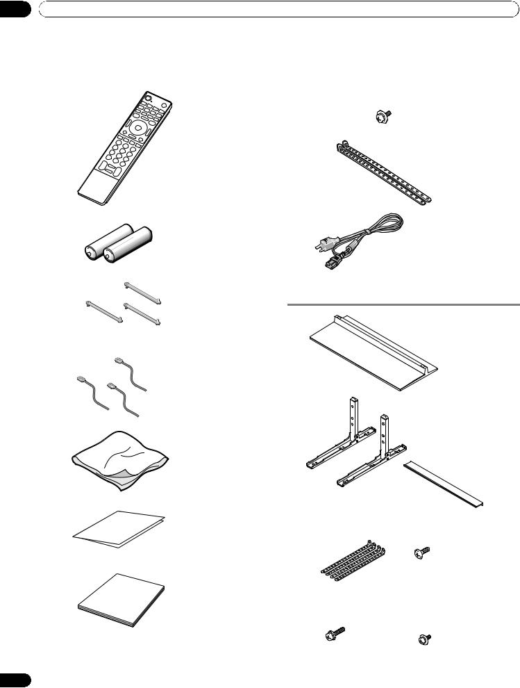
Supplied Accessories
Remote control unit
AA size battery × 2 (Alkaline batteries for remote control unit)
Screw (M4 x 10 mm) x 2 (for plastic bands) (PRO-110FD only)
Plastic band x 2 (PRO-110FD only)
Power cord (2 m/6.6 feet)
Speed clamp × 3
Bead band × 3
Cleaning cloth
Warranty card
Operating instructions
12
Stand accessories (PRO-150FD only)
Base cover x 1
Stand pipe (L) x 1
Stand pipe (R) x 1
Light-blocking shield x 1
Plastic band x 4
Screw
(M5 x 10 mm: black) x 6
Screw |
Screw |
(M6 x 20 mm: black) x 4 |
(for plastic bands) |
|
(M4 x 10 mm: black) x 4 |
En
Supplied Accessories
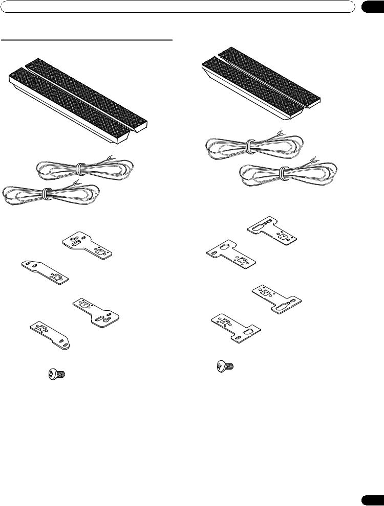
Speaker accessories
(PRO-150FD)
Speaker
Speaker cable × 2
Speaker Mounting Fittings
Bracket for TOP-Left
Bracket for BOTTOM-Left
Bracket for TOP-Right
Bracket for BOTTOM-Right
Speaker mounting screw (M5 × 10 mm: black) × 16
03
(PRO-110FD)
Speaker
Speaker cable × 2
Speaker Mounting Fittings
For TOP-Left
For BOTTOM-Left
For TOP-Right
For BOTTOM-Right
Speaker mounting screw (M5 × 10 mm: black) × 14
13
En
04 Part Names
Chapter 4
Part Names
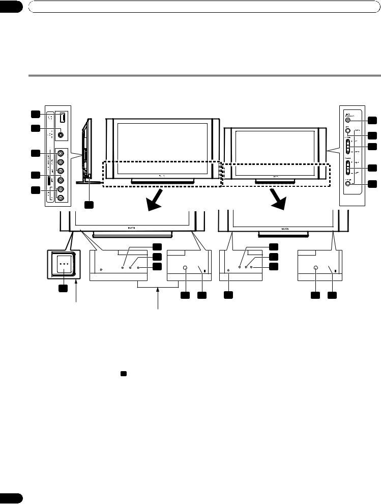
Plasma display
(Front) |
|
|
|
|
|
|
Side |
12 |
Side |
PRO-150FD |
PRO-110FD |
|
|
7 |
|
13 |
|
|
|
|
|
8 |
|
|
|
|
|
14 |
|
|
9 |
|
|
|
|
15 |
|
|
10 |
|
|
11 |
|
16 |
|
|
|
|
|
|
1
|
2 |
|
|
2 |
|
|
3 |
|
|
3 |
|
|
4 |
|
|
4 |
|
1 |
5 |
6 |
1 |
5 |
6 |
|
|||||
Viewed from below of |
Viewed from the front |
|
|
|
|
the display |
|
|
|
||
side of the display |
|
|
The terminals on side panels are common |
||
|
|
|
|||
to the PRO-150FD and PRO-110FD.
1a button (This button is located on the bottom of the side panel of the plasma display for the PRO-150FD and at the bottom on the rear panel for the PRO-110FD (see 1 on page 15). If the button is off, the power will not turn on even when TV a on the remote control unit or STANDBY/ON on the plasma display is pressed. To turn on the power, press a.)
2POWER ON indicator (See page 32.)
3STANDBY indicator (See page 32.)
4SLEEP indicator
5Room Light Sensor
6Remote control sensor
7STANDBY/ON button
8INPUT button (ENTER button*)
14
9VOLUME UP/DOWN buttons (UP/DOWN buttons*)
10CHANNEL UP/DOWN buttons (LEFT/RIGHT buttons*)
11TV GUIDE button*
12USB port
13PHONES output terminal
14INPUT 3 terminals (COMPONENT VIDEO: Y, PB, PR)
15INPUT 3 terminal (VIDEO)
16INPUT 3 terminals (AUDIO)
The buttons with asterisks (*) can operate the TV Guide On Screen™ system.
En
Part Names |
|
|
|
|
|
|
|
|
|
|
|
|
|
|
|
04 |
||||||||||||||||||||||||||||||
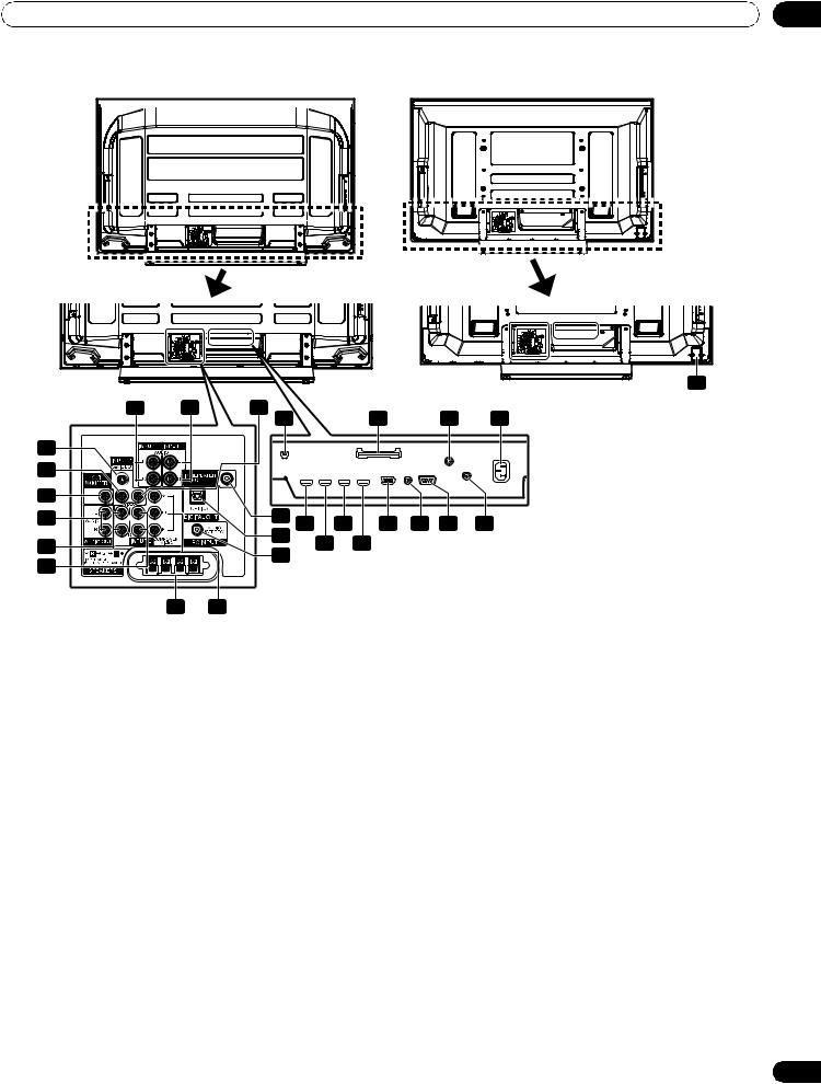
(Rear) |
PRO-150FD |
|
|
|
|
|
|
|
PRO-110FD |
|||||||||||||||||||||||||||||||||||||
|
|
|
|
|
|
|
|
|
|
|
|
|
|
|
|
|
|
|
|
|
|
|
|
|
|
|
|
|
|
|
|
|
|
|
|
|
|
|
|
|
|
|
|
|
|
|
|
|
|
|
|
|
|
|
|
|
|
|
|
|
|
|
|
|
|
|
|
|
|
|
|
|
|
|
|
|
|
|
|
|
|
|
|
|
|
|
|
|
|
|
|
|
|
|
|
|
|
|
|
|
|
|
|
|
|
|
|
|
|
|
|
|
|
|
|
|
|
|
|
|
|
|
|
|
|
|
|
|
|
|
|
|
|
|
|
|
|
|
|
|
|
|
|
|
|
|
|
|
|
|
|
|
|
|
|
|
|
|
|
|
|
|
|
|
|
|
|
|
|
|
|
|
|
|
|
|
|
|
|
|
|
|
|
|
|
|
|
|
|
|
|
|
|
|
|
|
|
|
|
|
|
|
|
|
|
|
|
|
|
|
|
|
|
|
|
|
|
|
|
|
|
|
|
|
|
|
|
|
|
|
|
|
|
|
|
|
|
|
|
|
|
|
|
|
|
|
|
|
|
|
|
|
|
|
|
|
|
|
|
|
|
|
|
|
|
|
|
|
|
|
|
|
|
|
|
|
|
|
|
|
|
|
|
|
|
|
|
|
|
|
|
|
|
|
|
|
|
|
|
|
|
|
|
|
|
|
|
|
|
|
|
|
|
|
|
|
|
|
|
|
|
|
|
|
|
|
|
|
|
|
|
|
|
|
|
|
|
|
|
|
|
|
|
|
|
|
|
|
|
|
|
|
|
|
|
|
|
|
|
|
|
|
|
|
|
|
|
|
|
|
|
|
|
|
|
|
|
|
|
|
|
|
|
|
|
|
|
|
|
|
|
|
|
|
|
|
|
|
|
|
|
|
|
|
|
|
|
|
|
|
|
|
|
|
|
|
|
|
|
|
|
|
|
|
|
|
|
|
|
|
|
|
|
|
|
|
|
|
|
|
|
|
|
|
|
|
|
|
|
|
|
|
|
|
|
|
|
|
|
|
|
|
|
|
|
|
|
|
|
|
|
|
|
|
|
|
|
|
|
|
|
|
|
|
|
|
|
|
|
|
|
|
|
|
|
|
|
|
|
|
|
|
|
|
|
|
|
|
|
|
|
|
|
|
|
|
|
|
|
|
|
|
|
|
|
|
|
|
|
|
|
|
|
|
|
|
|
|
|
|
|
|
|
|
|
|
|
|
|
|
|
|
|
|
|
|
|
|
|
|
|
|
|
|
|
|
|
|
|
|
|
|
|
|
|
|
|
|
|
|
|
|
|
|
|
|
|
|
|
|
|
|
|
|
|
|
|
|
|
|
|
|
|
|
|
|
|
|
|
|
|
|
|
|
|
|
|
|
|
|
|
|
|
|
|
|
|
|
|
|
|
|
|
|
|
|
|
|
|
|
|
|
|
|
|
|
|
|
|
|
|
|
|
|
|
|
|
1
20 |
21 |
22 |
2 |
3 |
4 |
5 |
14 |
4 |
5 |
15
16 |
|
23 |
|
|
|
|
|
17 |
|
6 |
8 |
10 |
11 12 |
13 |
|
18 |
|
24 |
|||||
|
25 |
|
7 |
9 |
|
|
|
19 |
|
|
|
|
|
|
|
|
*For exact terminal positions, refer to |
||||||
|
|
||||||
27 |
26 |
the terminal position sheet located |
|||||
near the terminal compartment. |
|||||||
The terminals on the rear panel are common to the
PRO-150FD and PRO-110FD.
1 |
a button |
17 |
AUDIO OUT terminals (AUDIO) |
2 |
Ethernet cable port |
18 |
INPUT 1 terminals (AUDIO) |
3 |
CableCARD™ slot |
19 |
INPUT 2 terminals (AUDIO) |
4 |
ANT/CABLE A IN terminal |
20 |
INPUT 4 terminals (AUDIO) |
5 |
AC IN terminal |
21 |
INPUT 5 terminals (AUDIO) |
6 |
INPUT 4 terminal (HDMI) |
22 |
INPUT 2 terminal (VIDEO) |
7 |
INPUT 5 terminal (HDMI) |
23 |
IR REPEATER OUT terminal |
8 |
INPUT 6 terminal (HDMI) |
24 |
DIGITAL OUT terminal (OPTICAL) |
9 |
INPUT 7 terminal (HDMI) |
25 |
PC INPUT terminal (AUDIO) |
10 |
PC INPUT terminal (ANALOG RGB) |
26 |
INPUT 2 terminals (COMPONENT VIDEO: Y, PB, |
11 |
CONTROL OUT terminal (supports SR+) |
|
PR) |
12 |
RS-232C terminal (used for factory setup) |
27 |
SPEAKERS (R/L) terminals |
13ANT B IN terminal
14INPUT 1 terminal (S-VIDEO)
15INPUT 1 terminal (VIDEO)
16SUBWOOFER terminal
15
En
04 Part Names
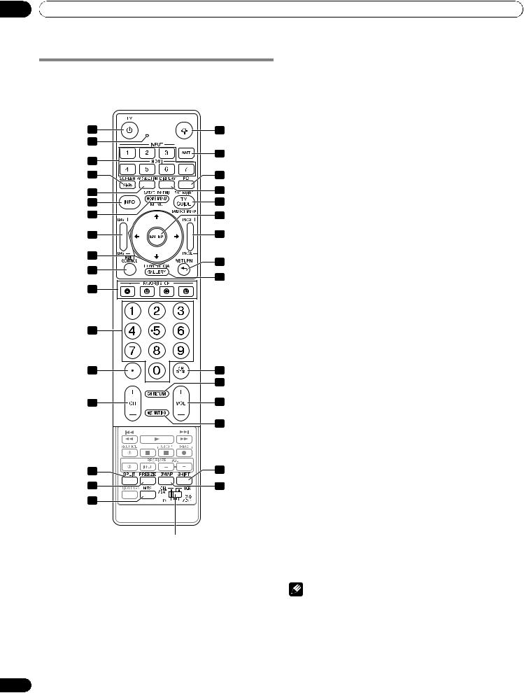
Remote control unit
This section describes the functions of the buttons available when the mode switch has been set to TV. For the buttons for controlling other equipment, see Using the remote control unit to control other devices starting from page 105.
1 |
18 |
|
2 |
|
|
3 |
19 |
|
|
||
4 |
20 |
|
5 |
21 |
|
6 |
22 |
|
7 |
23 |
|
8 |
24 |
|
9 |
25 |
|
10 |
||
26 |
||
|
||
11 |
|
|
12 |
|
|
13 |
27 |
|
|
28 |
|
14 |
29 |
|
|
30 |
|
15 |
31 |
|
16 |
32 |
|
17 |
|
Mode switch (with “TV” selected)
16
1TV a: Turns on the power to the plasma display or places it into standby mode.
2Transmission confirmation LED
3INPUT: Selects an input source of the plasma display. (“INPUT 1”, “INPUT 2”, “INPUT 3”, “INPUT 4”, “INPUT 5”, “INPUT 6” and “INPUT 7”)
4SCREEN SIZE: Selects the screen size.
5AV SELECTION: Selects audio and video settings. (AV source: OPTIMUM, STANDARD, DYNAMIC, MOVIE, PURE, GAME, USER. PC source: STANDARD, USER.)
6INFO: Displays a channel banner when a TV program is being watched.
When the TV Guide On Screen™ system is in operation, displays information about the currently highlighted channel (if available).
7HOME MENU: Displays the HOME MENU screen.
MENU: Displays a panel menu when the TV Guide On Screen™ system is in operation.
8DAY +/–: Jumps to the next or previous day of program listings in the TV Guide On Screen™ Listing service.
9 /
/ /
/  /
/  : Selects a desired item on the menu screen.
10HDMI CONTROL: Displays the HDMI Control menu.
11FAVORITE CH (A, B, C, D):
Selects any of the four preset channels. See page 48 for details to set the FAVORITE CH.
While watching, you can toggle the set channels by pressing A, B, C and D.
120 to 9: Selects the channel.
13•(dot): Enters a dot.
14CH +/–: Selects the channel.
15SPLIT: Switches the screen mode among 2-screen, picture-in- picture, and single-screen.
16FREEZE: Freezes a frame from a moving image. Press again to cancel the function.
17MTS: Selects MTS/SAP or language depending on the program being watched.
18D: Lights up all buttons
Lights turn off if no operations are performed within five seconds. This is used for remote control use in dark locations.
19ANT: Selects the antenna (A, B). See page 29 for details.
20PC: Selects the PC terminal as an input source.
21DISPLAY: Displays the channel information.
22TV GUIDE: Displays the TV Guide On Screen™ system.
23ENTER: Executes a command.
24PAGE +/– (for the TV Guide On Screen™ system): Scrolls the program listing screen vertically.
25RETURN: Returns to the previous menu screen.
26HOME MEDIA GALLERY: Displays the Home Media Gallery screen.
27CH ENTER: Executes a channel number.
28CH RETURN: Returns to the previous channel. This button is disabled while the TV Guide On Screen™ system is displayed.
29VOL +/–: Sets the volume.
30M MUTING: Mutes the sound.
31SHIFT: Moves the location of the small screen when in the picture-in-picture mode.
32SWAP: Switches between the two screens when in the 2-screen or picture-in-picture mode.
Note
•When using the remote control unit, point it at the plasma display.
•See pages 98 to 108 for operating buttons not listed on this page.
En
Preparation |
05 |
Chapter 5
Preparation
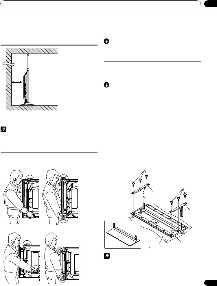
Installing the plasma display
Over 50 cm (19-11/16 inches)
Over 10 cm (3-5/16 inches)
Location
• Avoid direct sunlight. Maintain adequate ventilation.
Note
•Allow enough space around the upper and back parts when installing to ensure adequate ventilation of the rear of the unit.
Moving the plasma display
Because the plasma display is heavy, be sure to have someone help you when moving it.
(PRO-150FD)
(PRO-110FD)
Caution
When installing on a rack, etc., hold the plasma display.
Attaching the Pioneer stand
The plasma display comes with the Pioneer table top stand. You can also install the display on a rack by detaching the stand. The method for attaching/detaching the stand varies depending on the product.
Caution
•This product can be used only with the attached stand. Using other stands can result in instability, possibly causing injury.
•The weight of a 60 inch plasma display is about 55.5 kg (122.4 lbs.) and a 50 inch about 38.8 kg (85.5 lbs.), it has no depth, and is unstable. Therefore, at least two people must assemble and install it.
Assembling the stand (PRO-150FD only)
1Turn the base cover over so the underside is facing up.
2Insert the stand pipes into the base cover.
Insert stand pipe (R) into the side marked “R” and stand pipe
(L) into the side marked “L”.
3Tighten the screws 1 (M5 x 10 mm: black) to stabilize the stand pipes.
Screws
(M5 x 10 mm: black)
Screws
(M5 x 10 mm: black)
Stand
pipe with “R” inscribed
Rear
Stand
pipe with “L” inscribed
Completed
Table top stand
Front
Sheet |
Base cover |
|
Note
•Assemble the stand with a soft sheet placed under the base cover. If a sheet is not laid before assembly, the front surface of the base cover may be scratched.
•Please take care when installing stand pipes (L) and (R) to ensure that they are in the correct positions. Mistakenly
installing the stand pipes may damage the stand. |
17 |
En
05 Preparation
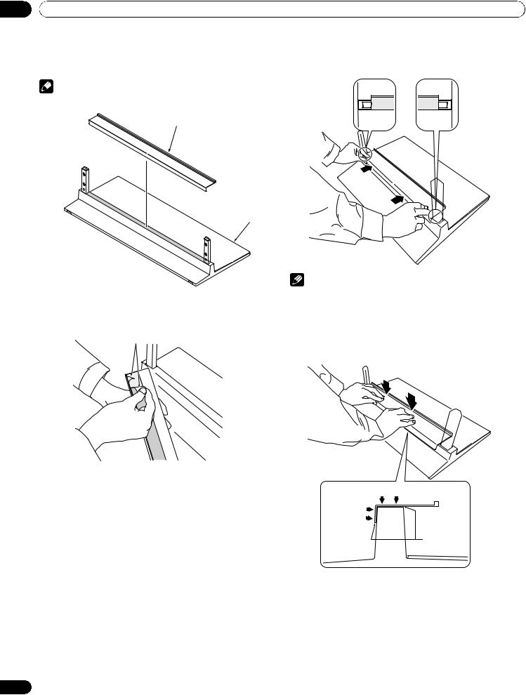
Attaching the light-blocking shield (PRO-150FD only)
This part prevents reflection of the cables connected to the back of the plasma display on the base cover.
Note
• Attach it after anchoring the base cover on a flat stable place.
Light-blocking shield
Front
Base cover
Rear
2While firmly holding the ends of the lightblocking shield, apply it with the doublesided adhesive tape.
Front
Rear
1Remove the double-sided adhesive tape from the light-blocking shield.
Remove each double-sided adhesive tape.
Note
•Be careful that the light-blocking shield does not catch on the pipe insertion holes.
•Anchor it in place so that there are no gaps (See diagram at below). If there is a gap, the light-blocking shield may peel off.
3Anchor it in place while pressing it down from above.
Front
Rear
Press
Press
Be sure that there is no gap.
18
En
Preparation |
05 |
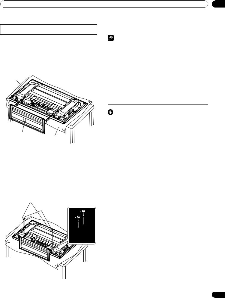
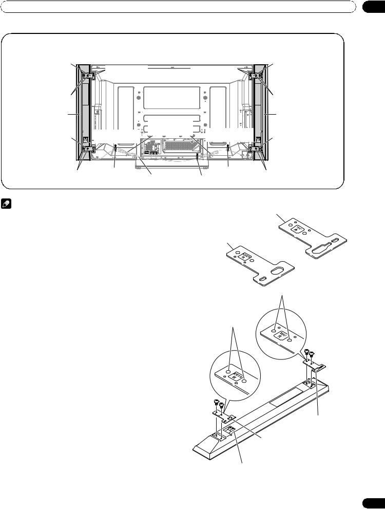
Attaching the stand
•Steps for attaching the stand are the same for PRO-150FD and PRO-110FD (use the screw holes with “T” inscribed).
1With the plasma display lying flat, fit the stand’s support columns to the bottom of the plasma display as indicated by the arrows, then slowly insert them.
•Be extremely careful not to insert the support columns of the stand into any part of the plasma display other than the stand insertion slots. Doing so might damage the plasma display panel or its ports or result in warping of the stand.
Plasma display
Insert the stand into the |
|
plasma display so that an |
Sheet |
arrow with “FRONT/FACE |
|
AVANT” mark inscribed at |
(PRO-150FD) |
the bottom of the stand |
|
indicates downward. |
|
2Attach the stand at the points indicated by the arrows and tighten the installation bolts (2) and (1) firmly using a screwdriver.
Installation bolts (1): M8 x 23 mm (black) for PRO-110FD M6 x 20 mm (black) for PRO-150FD
Installation bolts (2): M8 x 40 mm (black) for PRO-110FD M6 x 20 mm (black) for PRO-150FD
Installation bolts (1) (Step 2) Installation bolts (2)
(Step 1)
(PRO-150FD)
3Replace the plasma display to stand upright.
For speaker installation, see Installing the Pioneer speaker.
Note
•Be sure to install the plasma display in a flat, stable location.
•Insert the screws into the holes vertically and tighten them.
•Place a sheet or protective cover to protect the display from scratches or damage.
•Work only with the plasma display lying flat on a table or similar surface.
•When lying the plasma display down, be careful not to scratch or damage it.
•If the speaker has been installed, it is recommended to detach the speaker before attaching the stand.
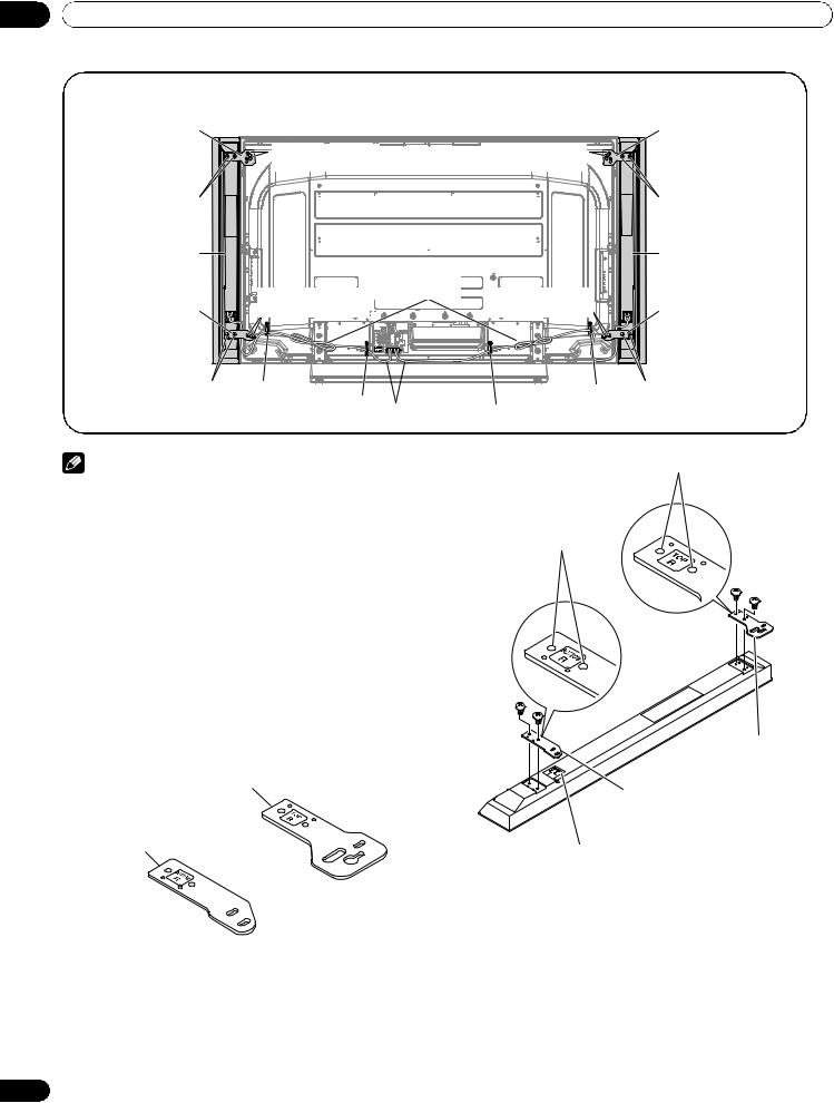
Installing the Pioneer speaker
Caution
•Do not move the display holding on to the mounting fittings. This can result in injury or damage to the unit.
About the speaker
•In order to prevent damage to the speaker system resulting from input overload, please observe the following precautions:
•Do not use the speaker with anything other than the plasma display. Doing so may result in damage or fire.
•Be sure to turn the connected devices off and remove the power cord from the power outlet beforehand when changing the connection or installation method.
•When using a tone control function to greatly emphasize treble sounds, do not use excessive amplifier volume.
•Please handle the speaker with sufficient care, as the grille net and the cabinet can become damaged or broken when they are subjected to strong external impacts.
•Placing a CRT computer screen or CRT monitor near to the speaker may result in interference or color distortion. If this happens, distance the monitor from the speaker.
Installation
•When installing the speaker, do not use any screws other than those supplied, otherwise the speaker may come off from the main unit and fall over.
•When installing the speaker, tighten the screws firmly.
19
En
05 Preparation
PRO-150FD with the speaker installed (with the Pioneer table top stand)
Speaker mounting fitting |
|
|
|
Speaker mounting fitting |
(for TOP-Right) |
Speaker mounting |
Speaker mounting |
(for TOP-Left) |
|
|
|
|||
|
screw (M5 x 10 mm) |
screw (M5 x 10 mm) |
|
|
Speaker mounting screw |
|
|
|
Speaker mounting screw |
(M5 x 10 mm) |
|
|
|
(M5 x 10 mm) |
Speaker |
|
Bead band |
|
Speaker |
|
|
|
|
|
|
|
(accessories of the |
|
|
|
Speaker mounting |
plasma display) |
Speaker mounting |
|
Speaker mounting fitting |
|
|
||
screw (M5 x 10 mm) |
|
screw (M5 x 10 mm) |
Speaker mounting fitting |
|
(for BOTTOM-Right) |
|
|
|
(for BOTTOM-Left) |
Speaker mounting screw |
Speed clamp |
(M5 x 10 mm) |
Speed clamp Speaker cable |
Note
•Before installing the speaker, make sure that the Pioneer table top stand is attached to the plasma display.
•When using the hang on wall unit, first lay the plasma display on top of a soft sheet, etc., remove the stand, then attach the speaker.
1Attach the speaker mounting fittings to the speakers.
•There is a left speaker and a right speaker. When you are mounting them, check the label on the back to get them right.
•There are top and bottom speaker mounting fittings for both the left and the right speaker. Attach the appropriate fittings to the top and the bottom on the back of the speakers using the supplied screws.
(It shows the attachment of the fitting on the right side. It is attached on the left side by the same procedure.)
Speaker mounting fitting (for TOP-Right)
(The skinny slot is used for mounting to the top.)
Speaker mounting fitting (for BOTTOM-Right)
Speed clamp Speaker mounting screw
(M5 x 10 mm)
Speed clamp
Screw holes
Screw holes
Speaker mounting fitting (for TOP-Right)
Speaker mounting fitting (for BOTTOM-Right)
Place the speaker so its terminals (bottom) are facing you.
20
En
Preparation |
05 |
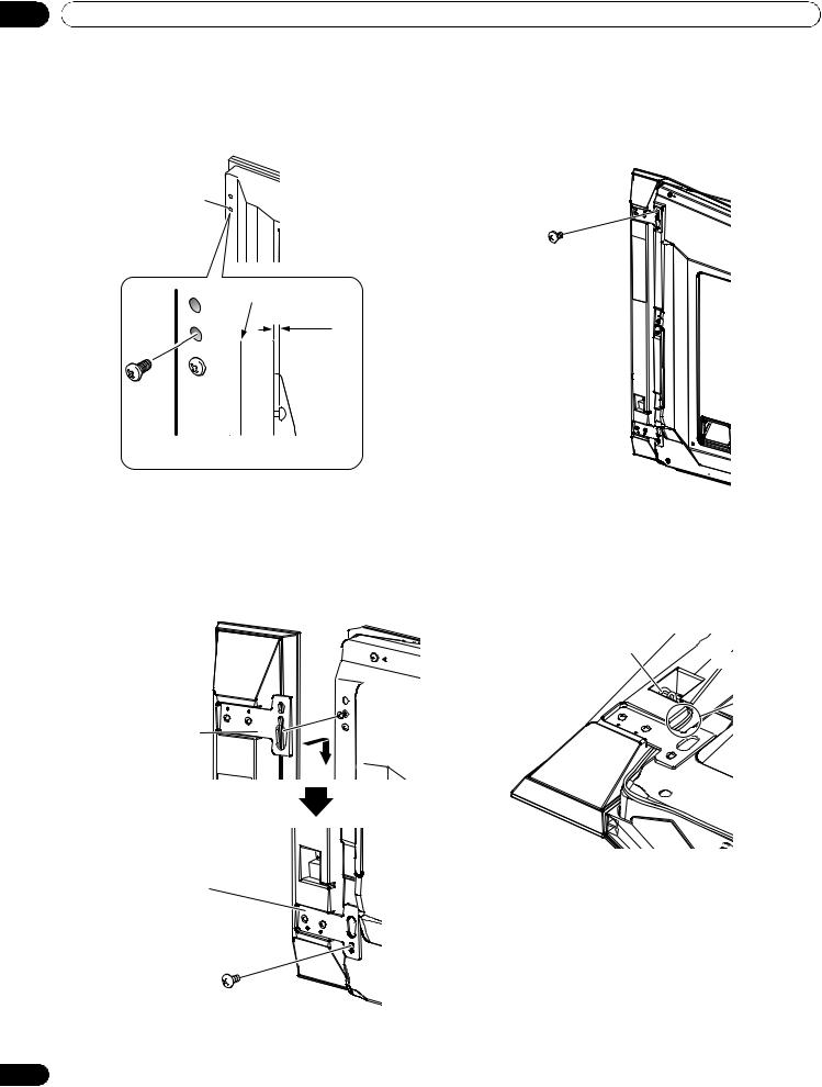
2Screw a supplied screw into the speaker mounting hole (lower of the two) at the top, rear of the display.
•Do not tighten it all the way yet. Leave it loose, with about 5 mm left to tighten.
Speaker |
|
mounting |
Top, rear of |
hole |
display |
Top of display
5 mm
Leave a space of about 5 mm
5Tighten the two screws, at the top and bottom for each speaker (total of four screws), thus fixing the speakers to the display.
3Hang the speaker mounting fitting on the screw you installed at the top by passing the wide part over it and lowering into the slot; screw in the lower screw temporarily.
After passing the wide part of the hole of the speaker mounting fitting (top) over the screw, lower the speaker onto it.
After passing the  wide part of hole over the screw, lower
  the speaker.
6Pass the supplied speaker cable between the speaker and the plasma display (below the speaker mounting fitting) from below.
7Connect the speaker cables to the speaker (see next page).
8Insert the cable in the groove on the speaker.
Speaker cable
Speaker terminal
Insertion in groove
Tighten with the provided screw the bottom speaker mounting fitting to the display temporarily (one place bottom).
4Adjust the position of the speaker and then tighten the upper and lower screws firmly.
9Connect the other end of the speaker cables to the rear of plasma display (see next page).
21
En
05 Preparation
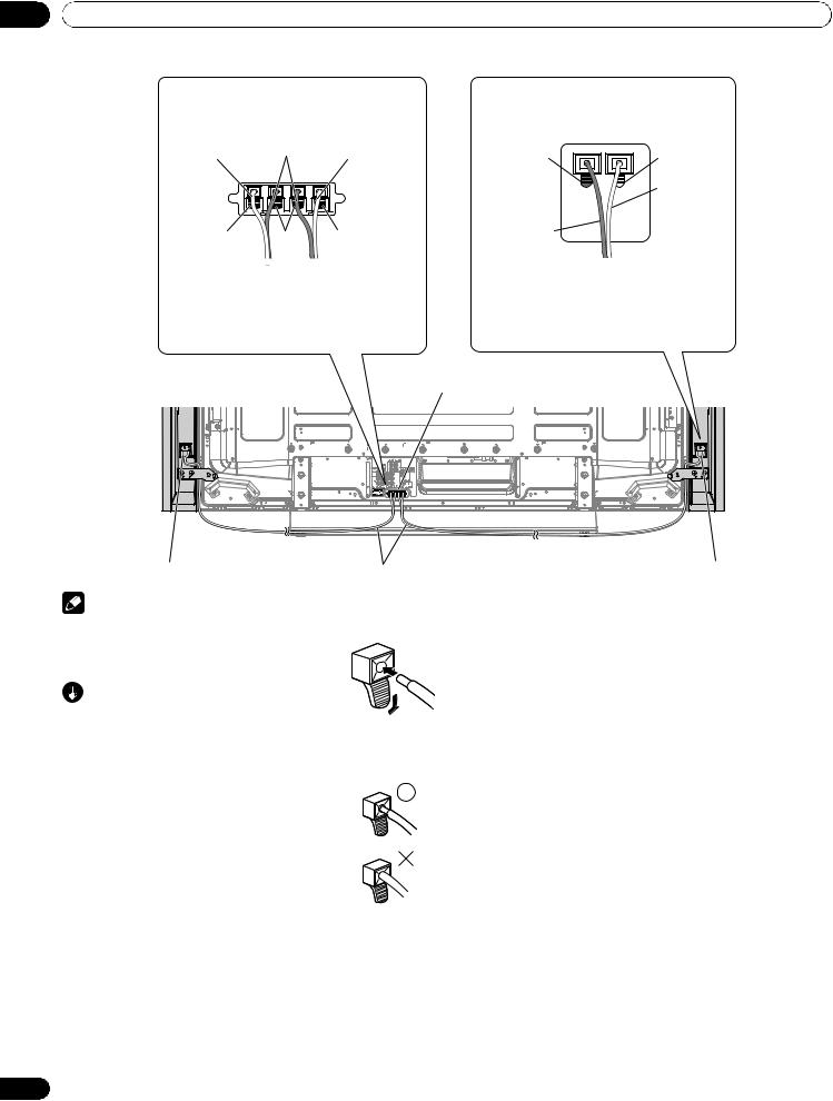
Connecting the speaker cables |
Connecting the speaker cables |
|||
to the rear of plasma display. |
to the speaker. |
|
||
Gray |
Black |
Gray |
Black |
Red |
|
|
|
||
|
|
|
|
Gray |
Red |
Black |
Red |
Black |
|
|
|
|||
Connect the cables correctly with respect to the polarity of the plasma display speaker terminals, that is, cable (Gray) to terminals (Red) and cable (Black) to terminals (Black).
Connect the cables correctly with respect to the polarity of the speaker terminals, that is,cable (Gray) to terminals (Red) and cable (Black) to terminals (Black).
Speaker
Speaker terminal |
Speaker cable |
Speaker terminal |
|
|
Note
•Press the lever and insert the end of the cable.
•When you release the lever, it
clamps onto the speaker cable.·
Caution
Lever
•Be sure to turn the connected devices off and remove the power
cord from the wall outlet beforehand when changing the connection or installation method.
•If you insert the speaker cable too far so that
the insulation is touching the speaker terminal, you may not get any sound.
•Check if the end of the speaker cables are securely connected to the terminals by slightly tugging on the cable after making connections. Loose connections may result in sound dropouts or noise.
•If there is a short in the and cables caused by an exposed lead wire, excessive load may be applied to the plasma display, resulting in interrupted operation or malfunction.
•Incorrect connections of the speaker cable to the right or left of the plasma display terminals with respect to the polarity may result in insufficient stereo sound effects, delivering poor bass sounds or unstable sound image.
•Bundle the cable without pulling.
22
En
Preparation |
05 |
PRO-110FD with the speaker installed (with the Pioneer table top stand)
Speaker mounting fitting |
|
|
|
Speaker mounting fitting |
(for TOP-Right) |
Speaker mounting |
|
Speaker mounting |
(for TOP-Left) |
|
screw (M5 x 10 mm) |
screw (M5 x 10 mm) |
|
|
Speaker mounting screw |
|
|
|
Speaker mounting screw |
|
|
|
(M5 x 10 mm) |
|
(M5 x 10 mm) |
|
|
|
|
|
|
|
|
|
Speaker |
|
Bead band |
|
Speaker |
|
|
|
|
|
|
|
(accessories of the |
|
|
Speaker mounting fitting |
Speaker mounting |
plasma display) |
Speaker mounting |
Speaker mounting fitting |
screw (M5 x 10 mm) |
|
screw (M5 x 10 mm) |
||
(for BOTTOM-Right) |
|
|
|
(for BOTTOM-Left) |
Speaker mounting screw |
Speed clamp |
|
Speed clamp |
Speaker mounting screw |
(M5 x 10 mm) |
Speaker cable |
Speed clamp |
(M5 x 10 mm) |
|
Note
•Before installing the speaker, make sure that the Pioneer table top stand is attached to the plasma display.
•When using the hang on wall unit, first lay the plasma display on top of a soft sheet, etc., remove the stand, then attach the speaker.
1Attach the speaker mounting fittings to the speakers.
•There is a left speaker and a right speaker. When you are mounting them, check the label on the back to get them right.
Speaker mounting fitting (for TOP-Right)
(The skinny slot is used for mounting to the top.)
Speaker mounting fitting (for BOTTOM-Right)
Screw holes
• There are top and bottom speaker mounting fittings for both the left and the right speaker. Attach the appropriate fittings to the top and the bottom on the back of the speakers using the supplied screws.
(It shows the attachment of the fitting on the right side. It is attached on the left side by the same procedure.)
Screw holes
Speaker mounting fitting (for TOP-Right)
Speaker mounting fitting (for BOTTOM-Right)
Place the speaker so its terminals (bottom) are facing you.
23
En
05 Preparation
2Screw a supplied screw into the speaker mounting hole (lower of the two) at the top, rear of the display.
•Do not tighten it all the way yet. Leave it loose, with about 5 mm left to tighten.
4Adjust the position of the speaker and then tighten the upper screw firmly.
5Tighten all screws firmly, thus fixing the speakers to the display.
Speaker |
Top, rear of |
|
mounting |
||
display |
||
hole |
||
|
Top of display
5 mm
Leave a space of about 5 mm
3Hang the speaker mounting fitting on the screw you installed at the top by passing the wide part over it and lowering into the slot; screw in the lower screw temporarily.
After passing the wide part of the hole of the speaker mounting fitting (top) over the screw, lower the speaker onto it.
After passing the wide part of hole over the screw, lower the speaker.
Tighten with the provided screw the bottom speaker mounting fitting to the display temporarily (one place bottom).
6Pass the supplied speaker cable between the speaker and the plasma display (below the speaker mounting fitting) from below.
7Connect the speaker cables to the speaker (see next page).
8Insert the cable in the groove on the speaker.
Speaker cable
Speaker terminal
Insertion in groove
9Connect the other end of the speaker cables to the rear of plasma display (see next page).
24
En
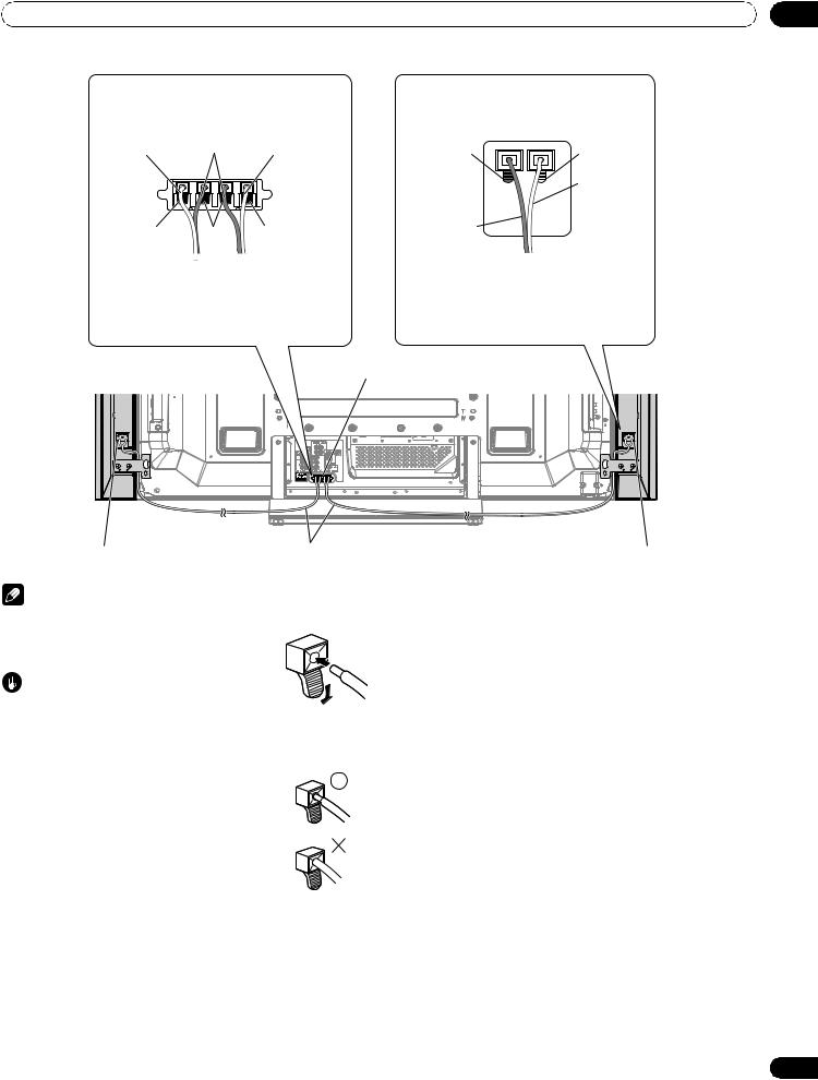
Preparation |
05 |
Connecting the speaker cables |
Connecting the speaker cables |
|||
to the rear of plasma display. |
to the speaker. |
|
||
Gray |
Black |
Gray |
Black |
Red |
|
|
|
||
|
|
|
|
Gray |
Red |
Black |
Red |
Black |
|
|
|
|||
Connect the cables correctly with respect to the polarity of the plasma display speaker terminals, that is, cable (Gray) to terminals (Red) and cable (Black) to terminals (Black).
Connect the cables correctly with respect to the polarity of the speaker terminals, that is,cable (Gray) to terminals (Red) and cable (Black) to terminals (Black).
Speaker terminal
Speaker terminal |
Speaker cable |
Note
•Press the lever and insert the end of the cable.
•When you release the lever, it
clamps onto the speaker cable.·
Caution
Lever
•Be sure to turn the connected devices off and remove the power
cord from the wall outlet beforehand when changing the connection or installation method.
•If you insert the speaker cable too far so that
the insulation is touching the speaker terminal, you may not get any sound.
Speaker terminal
•Check if the end of the speaker cables are securely connected to the terminals by slightly tugging on the cable after making connections. Loose connections may result in sound dropouts or noise.
•If there is a short in the and cables caused by an exposed lead wire, excessive load may be applied to the plasma display, resulting in interrupted operation or malfunction.
•Incorrect connections of the speaker cable to the right or left of the plasma display terminals with respect to the polarity may result in insufficient stereo sound effects, delivering poor bass sounds or unstable sound image.
•Bundle the cable without pulling.
25
En
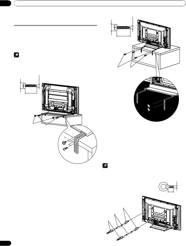
05 Preparation
Preventing the plasma display from falling over
After installing the stand, be sure to take special care to ensure that the plasma display will not fall over and is stabilized to both the wall and rack.
Stabilizing on a table or rack
Stabilize the plasma display as shown in the diagram using the supplied plastic bands and screws.
Note
•To stabilize the plasma display on a table or rack, also use commercially available wood screws that have a nominal diameter of 4 mm (5/32 inch) and that are at least 20 mm (13/16 inch) long.
mm15tomm |
inch)5/8toinch |
4 mm |
inch)(5/32 |
(PRO-150FD) |
|
|
|
||
|
|
|
|
|
|
|
20 mm min. |
|
|
8 |
(3/8 |
(13/16 inch) |
|
|
|
|
|
Supplied screw |
Wood screw |
(M4 x 10 mm) |
(commercially available, |
|
|
|
4 mm x 20 mm min.) |
|
(5/32 inch x 13/16 inch) |
Supplied screw
Wood screw
Drill a hole in the middle at the rear of the tabletop panel before using a wood screw. Perform this work the same way on the left and right sides.
15tommmm |
5/8toinchinch) |
20 mm min. |
(5/32 inch) |
(PRO-110FD) |
|
|
mm4 |
|
|
8 |
(3/8 |
(13/16 inch) |
|
|
|
|
|
|
Supplied screw |
Wood screw |
(M4 x 10 mm) |
(commercially available, |
|
4 mm x 20 mm min.) |
|
(5/32 inch |
Supplied screw
Wood screw
Drill a hole in the middle at the rear of the tabletop panel before using a wood screw. Perform this work the same way on the left and right sides.
Using a wall for stabilization
1Attach falling prevention bolts (hooks) to the plasma display.
2Use strong cords to stabilize it appropriately and firmly to a wall, pillar, or other sturdy element.
Perform this work in the same way on the left and right sides.
Note
•Use hooks, cords and fittings that are available on the market. Recommended hook: Nominal diameter 8 mm, length 12 mm to 18 mm (0.5 inches to 0.7 inches)
M8
12 mm to 18 mm
(0.5 inches to 0.7 inches)
1. Hook
2. Cord
Fitting
26
En
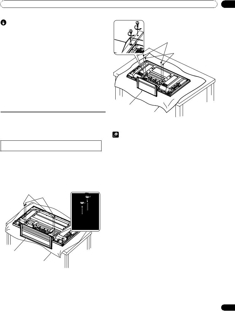
Preparation |
05 |
Caution
•A table or rack with adequate strength should always be used to support the plasma display. Failure to do so could result in personal injury and physical damage.
•When installing the plasma display, please take the necessary safety measures to prevent it from falling or overturning in case of emergencies, such as earthquakes, or of accidents.
•If you do not take these precautions, the plasma display could fall down and cause injury.
•The screws, hooks, cords and other fittings that you use to secure the plasma display to prevent it from overturning will vary according to the composition and thickness of the surface to which it will be attached.
•Select the appropriate screws, hooks, cords, and other fittings after first inspecting the surface carefully to determine its thickness and composition and after consulting a professional installer if necessary.
Detaching the Pioneer stand
You can also install the display on a rack by detaching the stand. The method for attaching/detaching the stand varies depending on the product.
Detaching the stand
•Steps for detaching the stand are the same for PRO-150FD and PRO-110FD.
1With the plasma display lying flat, loosen and remove the two installation bolts (1) and (2) using a screwdriver.
Installation bolts (1): M8 x 23 mm (black) for PRO-110FD M6 x 20 mm (black) for PRO-150FD
Installation bolts (2): M8 x 40 mm (black) for PRO-110FD M6 x 20 mm (black) for PRO-150FD
Installation bolts (1)
(Step 1) Installation bolts (2)
(Step 2)
Table top stand
Sheet
(PRO-150FD)
Installation bolts (1) (Step 1)
Installation bolts (2) (Step 2)
Table top stand
Sheet
(PRO-110FD)
2 Remove the stand from the plasma display.
Note
•Make sure to keep the installation bolts (1) and (2) that have been removed as they are re-used when attaching the stand to the plasma display.
•Place a sheet or protective cover to protect the display from scratches or damage.
•Work only with the plasma display lying flat on a table or similar surface.
•When lying the plasma display down, be careful not to scratch or damage it.
•If the speaker has been installed, it is recommended to detach the speaker before removing the stand.
27
En

05 Preparation
Attaching the stand again
•Steps for attaching the stand are the same for PRO-150FD and PRO-110FD (use the screw holes with “T” inscribed).
1With the plasma display lying flat, fit the stand’s support columns to the bottom of the plasma display as indicated by the arrows, then slowly insert them.
•Be extremely careful not to insert the support columns of the stand into any part of the plasma display other than the stand insertion slots. Doing so might damage the plasma display panel or its ports or result in warping of the stand.
Plasma display
Insert the stand into the plasma display so that an arrow with “FRONT/FACE AVANT” mark inscribed at the bottom of the stand indicates downward.
Plasma display
Sheet
(PRO-150FD)
Line up the column supports with the bottom of the plasma display, as indicated in the accompanying diagram.
Insert the stand into the |
Sheet |
|
plasma display so that an |
|
|
arrow with “FRONT/FACE |
(PRO-110FD) |
|
AVANT” mark inscribed at |
||
|
||
the bottom of the stand |
|
|
indicates downward. |
|
2Attach the stand at the points indicated by the arrows and tighten the installation bolts (2) and (1) firmly using a screwdriver.
Installation bolts (1): M8 x 23 mm (black) for PRO-110FD M6 x 20 mm (black) for PRO-150FD
28
Installation bolts (2): M8 x 40 mm (black) for PRO-110FD M6 x 20 mm (black) for PRO-150FD
Installation bolts (1) (Step 2)
Installation bolts (2)
(Step 1)
(PRO-150FD)

 Screw hole with
 “T” inscribed
Installation bolts (1) (Step 2)
Installation bolts (2) (Step 1)
(PRO-110FD)
3Replace the plasma display to stand upright.
For speaker installation, see Installing the Pioneer speaker on page 19.
Note
•Be sure to install the plasma display in a flat, stable location.
•Insert the screws into the holes vertically and tighten them.
•Place a sheet or protective cover to protect the display from scratches or damage.
•Work only with the plasma display lying flat on a table or similar surface.
•When lying the plasma display down, be careful not to scratch or damage it.
•If the speaker has been installed, it is recommended to detach the speaker before attaching the stand.
En
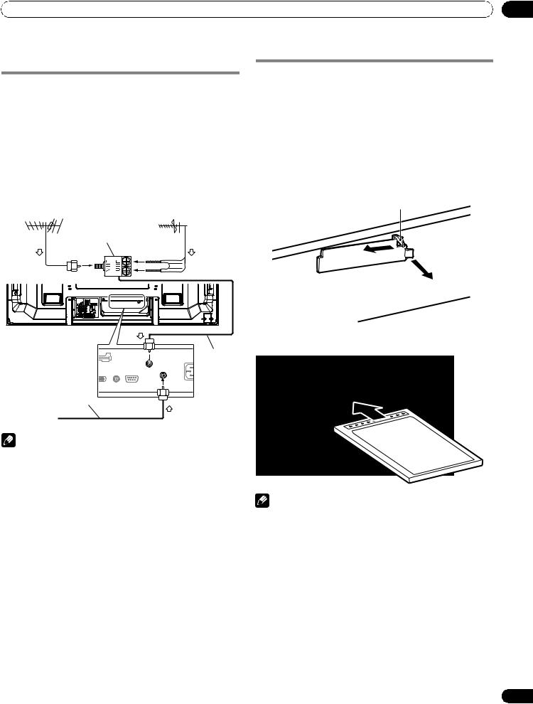
Preparation |
05 |
Cable connections for watching digital and/or conventional TV channels
This system is equipped with two terminals for inputting TV broadcasting signals: ANT/CABLE A IN and ANT B IN. The ANT/ CABLE A IN terminal accepts both digital and conventional TV broadcasting signals while the ANT B IN terminal accepts only conventional TV broadcasting signals. When using cable TV to watch digital and/or conventional TV channels, connect to the ANT/CABLE A IN terminal as shown. In addition, you may connect an antenna to the ANT B IN terminal as shown; use an outdoor antenna to enjoy clearer pictures. If your outdoor antenna uses a 75-ohm coaxial cable with an F-type connector, plug it into the antenna terminal at the rear of the plasma display.
Connecting VHF/UHF antennas and a Cable
VHF antenna |
UHF antenna |
U/Vmixer
Coaxial
Coaxial
Cable TV
Note
•Be sure to connect coaxial cables as shown above. Signal reception may fail if not properly connected.
•In order to watch cable TV channels, be sure to connect the cable to the ANT/CABLE A IN terminal.
•The ANT/CABLE A IN and ANT B IN terminals must not receive the same signals. For example, do not connect a cable from a cable TV to both the ANT/CABLE A IN and ANT B IN terminals. Similarly, do not connect a cable from an antenna to both the ANT/CABLE A IN and ANT B IN terminals.
•TV Guide may not be available in all areas and is not available with satellite systems. In addition, as content providers move to digital programming and broadcasting, TV Guide Data may be unavailable or become unavailable.
Inserting the CableCARD™
The plasma display is equipped with a slot for inserting a CableCARD™. When you are watching digital and/or High Definition TV channels over cable, the card allows you to use the POD service provided by the cable TV company; the POD stands for Point of Deployment. This service presents various types of useful information, using HTML text.
1Confirm that the ANT/CABLE A IN terminal has been connected with the coaxial cable from the Cable Converter.
2Hold and push the tab of the slot cover on the rear of the plasma display leftward, and remove the cover while pulling the tab’s latch downward.
(Viewed from below of the Tab plasma display)
1
2
3Insert the specified CableCARD™ into the Cable CARD slot as far as it goes.
Note
•Be sure to insert only the specified CableCARD™.
•Do not insert a PC card.
•When you use a CableCARD™, you need not execute Auto Channel Preset; the CableCARD™ automatically generates a cable channel list.
29
En
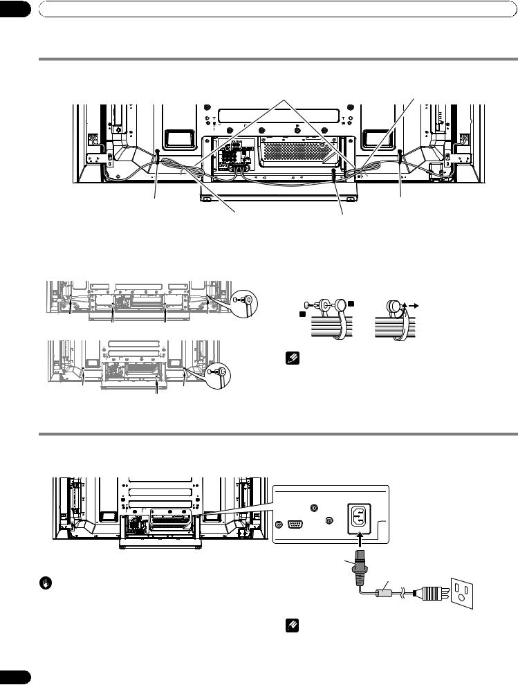
05 Preparation
Routing cables
When the speaker is installed under the plasma display panel (for PRO-110FD)
Rear view
Speed clamp
Bead band
Bead band
Speed clamp
Speed clamp
Attaching speed clamps to the main unit
Attach the speed clamps using the three holes (60 inches: four holes) marked with  below, depending on your routing system.
for PRO-150FD
for PRO-110FD
Attaching and removing speed clamps
Insert [1] into an appropriate hole on the rear of the plasma display and snap [2] into the back of [1] to lock the clamp. Speed clamps are designed to be difficult to undo once in place. Please attach them carefully.
Use pliers to twist the clamp 90º, pulling outward. The clamp may deteriorate over time and become damaged if removed.
2
1
Note
•Use the supplied bead bands and speed clamps as necessary.
•When tidying up your speaker cables, make sure to bundle them so that they are not subjected to any pressure.
Connecting the power cord
Connect the power cord after all component connections have been completed.
Plasma display (rear view)
Caution
•Use only the supplied power cord.
•Be sure to use the specified power supply voltage; neglecting this can result in fire or electric shock.
•For the plasma display, a three-core power cord with a ground terminal is used for efficient protection. Always connect the power cord to a three-pronged outlet and make sure that the cord is properly grounded.
30
AC IN terminal is located on the upper edge of the compartment.
Noise filter
Power cord |
Partially eliminates noise |
caused by the power source.
Note
•Always turn off the power of the plasma display when connecting or disconnecting power cords.
•Disconnect the power cord from the power outlet when the plasma display is not going to be used for a long period of time.
En
 Loading...