

Pioneer AVIX-Z3 User Manual

INSTALLATION MANUAL
MANUEL D’INSTALLATION
HDD MULTIMEDIA AV NAVIGATION SERVER
SERVEUR DE NAVIGATION AV MULTIMED IA SUR
DISQUE DUR
AVIC-Z3
English Français
Contents
Important Safety Information
ABOUT THIS MANUAL 3
PLEASE READ ALL OF THESE
INSTRUCTIONS REGARDING YOUR
NAVIGATION SYSTEM AND RETAIN THEM
FOR FUTURE REFERENCE 3
Connecting the System
Precautions before connecting the
system 4
Before installing this product 5
To prevent damage 5
– Notice for the blue lead 5
– Notice for the blue/white lead 6
Parts supplied 6
Connecting the system 8
Connecting the multi-channel processor 10
Connecting the power cord (1) 12
Connecting the power cord (2) 14
When connecting to separately sold power
amp 16
When connecting a rear view camera 18
When connecting the external video
component 19
When connecting the external unit featuring
video source 19
When connecting the rear display 20
– When using a rear display connected to
rear video output 20
– Installation using the screw holes on
the side of the navigation unit 24
Installing the GPS antenna 25
– Installation notes 25
– Parts supplied 25
– When installing the antenna inside the
vehicle (on the rear shelf) 26
– When installing the antenna outside
the vehicle (on the body) 27
Installing the microphone 28
– Parts supplied 28
– Mounting on the sun visor 28
– Installation on the steering column 28
– Adjusting the microphone angle 29
After Installation
After Installing this Navigation System 30
Installation
Precautions before installation 21
To guard against electromagnetic
interference 21
Before installing 22
Installing this navigation system 22
– Installation notes 22
– Parts supplied 24
2
En
Important Safety
Information
Section
01
English
ABOUT THIS MANUAL
This manual explains how to install this navigation system in your vehicle. Operation of
this navigation system is explained in the separate operation manual or hardware manual
for the navigation system. Before operating
this navigation system, be sure to read
them.
PLEASE READ ALL OF THESE
INSTRUCTIONS REGARDING
YOUR NAVIGATION SYSTEM
AND RETAIN THEM FOR
FUTURE REFERENCE
1 Read this manual fully and carefully before in-
stalling your navigation system.
2 Keep this manual handy for future reference.
3 Pay close attention to all warnings in this
manual and follow the instructions carefully.
4 This navigation system may in certain circum-
stances display erroneous information regard-
ing the position of your vehicle, the distance
of objects shown on the screen, and compass
directions. In addition, the system has certain
limitations, including the inability to identify
one-way streets, temporary traffic restrictions
and potentially unsafe driving areas. Please
exercise your own judgment in the light of ac-
tual driving conditions.
5 As with any accessory in your vehicle’s inter-
ior, the navigation system should not divert
your attention from the safe operation of your
vehicle. If you experience difficulty in operat-
ing the system or reading the display, please
make adjustments while safely parked.
6 Please remember to wear your seat belt at all
times while operating your vehicle. If you are
ever in an accident, your injuries can be con-
siderably more severe if your seat belt is not
properly buckled.
7 Certain government laws may restrict the pla-
cement and use of navigation systems in your
vehicle. Please comply with all applicable
laws and regulations in the installation and
operation of your navigation system.
WARNING
Do not attempt to install or service your navigation system by yourself. Installation or servicing
of the navigation system by persons without training and experience in electronic equipment and
automotive accessories may be dangerous and
could expose you to the risk of electric shock or
other hazards.
En
3
Section
02
Connecting the System
Precautions before
connecting the system
WARNING
Pioneer does not recommend that you install
your navigation system yourself. We recommend that only authorized Pioneer service
personnel, who have special training and experience in mobile electronics, set up and install this product. NEVER SERVICE THIS
PRODUCT YOURSELF. Installing or servicing this product and its connecting cables
may expose you to the risk of electric shock
or other hazards, and can cause damage to
the navigation system that is not covered by
warranty.
CAUTION
! If you decide to perform the installation
yourself, and have special training and experience in the mobile electronics installations, please carefully follow all of the
steps in the installation manual.
! Secure all wiring with cable clamps or
electrical tape. Do not allow any bare wiring to remain exposed.
! Do not directly connect the yellow lead of
this product to the vehicle battery. If the
lead is directly connected to the battery,
engine vibration may eventually cause
the insulation to fail at the point where
the wire passes from the passenger compartment into the engine compartment. If
the yellow lead’s insulation tears as a result of contact with metal parts, short-circuiting can occur, resulting in
considerable danger.
! It is extremely dangerous to allow the
cables to become wound around the steering column or shift lever. Be sure to install
this product, its cables, and wiring away
in such a way that they will not obstruct
or hinder driving.
! Make sure that the cables and wires are
routed and secured so they will not interfere with or become caught in any of the
vehicle’s moving parts, especially the
steering wheel, shift lever, parking brake,
sliding seat tracks, doors, or any of the vehicle’s controls.
! Do not route wires where they will be ex-
posed to high temperatures. If the insulation heats up, wires may become
damaged, resulting in a short circuit or
malfunction and permanent damage to
the product.
! Do not cut the GPS antenna cable to
shorten it or use an extension to make it
longer. Altering the antenna cable could
result in a short circuit or malfunction.
! Do not shorten any leads. If you do, the
protection circuit (fuse holder, fuse resistor or filter, etc.) may fail to work properly.
! Never feed power to other electronic pro-
ducts by cutting the insulation of the
power supply lead of the navigation system and tapping into the lead. The current
capacity of the lead will be exceeded,
causing overheating.
! The black lead is ground. Please ground
this lead separately from the ground of
high-current products such as power
amps. Do not ground more than one product together with the ground from another product. For example, you must
separately ground any amp unit away
from the ground of this navigation system. Connecting grounds together can
cause a fire and/or damage the products if
their grounds became detached.
4
En
Connecting the System
Section
02
English
Before installing this
product
! This product is for vehicles with a 12-volt
battery and negative grounding. Check the
battery voltage of your vehicle before instal-
lation.
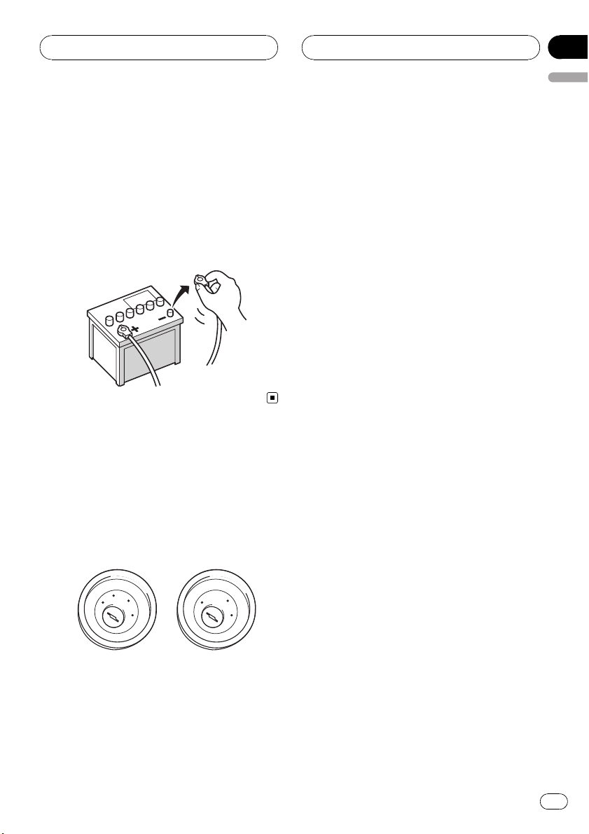
! To avoid shorts in the electrical system, be
sure to disconnect the (–) battery cable be-
fore beginning installation.
To prevent damage
! When disconnecting a connector, pull the
connector itself. Do not pull the lead, as
you may pull it out of the connector.
! This product cannot be installed in a vehi-
cle without ACC (accessory) position on
the ignition switch.
C
C
A
O
F
N
F
O
ACC position No ACC position
S
T
A
R
T
! When replacing the fuse, be sure to only
use a fuse of the rating prescribed on the
fuse holder.
! To avoid a short-circuit, cover the discon-
nected lead with insulating tape. Insulate
the unused speaker leads without fail.
O
F
N
F
O
S
T
A
R
T
There is a possibility of a short-circuit if the
leads are not insulated.
! Attach the connectors of the same color to
the corresponding colored port, i.e., blue
connector to the blue port, black to black,
etc.
! Refer to the owner’s manual for details on
connecting the power amp and other units,
then make connections accordingly.
! Since a unique BPTL circuit is employed,
do not directly ground the * side of the
speaker lead or connect the * sides of the
speaker leads together. Be sure to connect
the * side of the speaker lead to the *
side of the speaker lead on this navigation
system.
! If the RCA pin jack on this product will not
be used, do not remove the caps attached
to the end of the connector.
! Speakers connected to this navigation unit
must be high-power with minimum rating
of 50 W and impedance of 4 to 8 ohms.
Connecting speakers with output and/or
impedance values other than those noted
here may result in the speakers catching
fire, emitting smoke, or becoming damaged.
Notice for the blue lead
! A signal is output through the blue lead to
control the antenna of your vehicle. The
timing varies depending on the setting. (For
more detailed information on changing
[Auto ANT] mode, refer to the operation
manual.)
! When [Auto ANT] mode is set to [Radio],
the vehicle’s antenna can be stowed or
turned off by following the instructions
below.
— Change the source from radio (AM or
FM) to another source
— Turn the source off
— Turn off the ignition switch (ACC OFF)
En
5
Section
02
Connecting the System
! If [Auto ANT] mode is set to [Power], the
vehicle’s antenna can be stowed or turned
off only when the ignition switch is turned
off (ACC OFF).
! Do not connect this lead to the system con-
trol terminal of external power amps.
! Be sure not to use this lead as the power
supply lead for the auto-antenna or antenna booster. Such connection could cause
excessive current drain and malfunction.
Notice for the blue/white lead
! When the ignition switch is turned on (ACC
ON), a control signal is output through the
blue/white lead. Connect to an external
power amp’s system remote control terminal (max. 300 mA 12 V DC). The control signal is output through the blue/white lead,
even if the audio source is switched off.
! Do not connect this lead to the auto-anten-
na relay control terminal or the antenna
booster power control terminal.
! Be sure not to use this lead as the power
supply lead for the external power amps.
Such connection could cause excessive
current drain and malfunction.
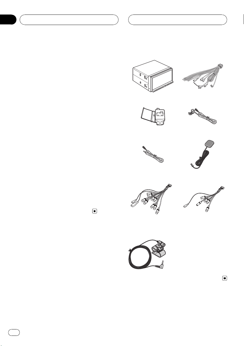
Parts supplied
The navigation unit Power cord
Connector Extension lead
Extension lead
(for speed signal)
RCA connector 1
(CONNECTOR 1)
<See page 10, 12, 16,
19>
<See Page 12, 14, 18>
(for reverse signal)
GPS antenna
RCA connector 2
(CONNECTOR 2)
<See Page 8, 10, 18, 20>
Microphone
6
En

Connecting the System
Section
02
English
En
7
Section
02
Connecting the System
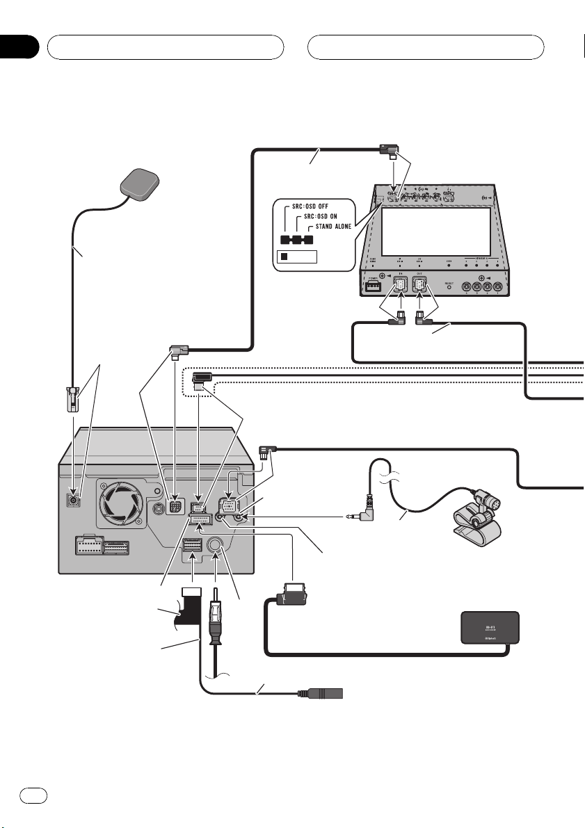
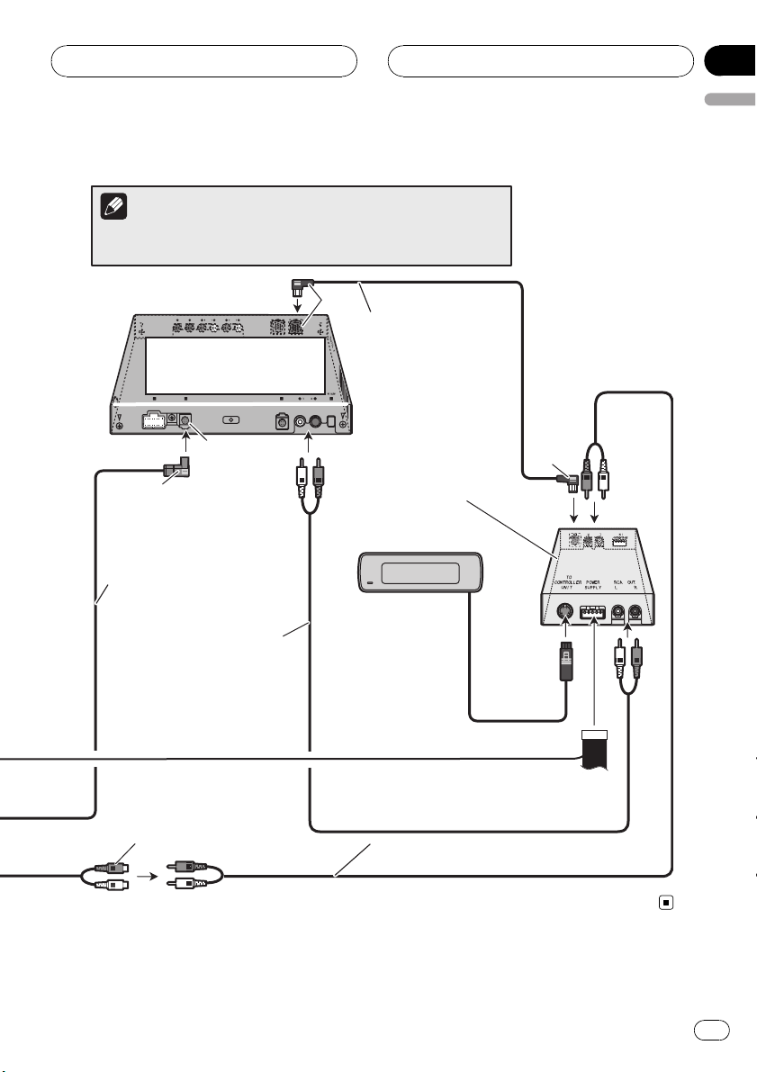
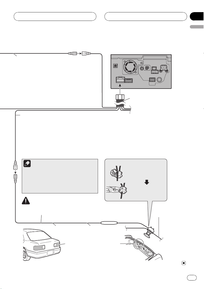
Connecting the system
GPS antenna
5 m (16 ft. 5 in.)
Light gray
Blue
The navigation unit
Red
RCA connector 2
Jack for Wired Remote
Control Adapters
(WIRED REMOTE INPUT)
Please see the instruction manual
for the Wired Remote Control
Adapters (sold separately).
AV-BUS cable
(supplied with TV tuner)
Black
Microphone input
Antenna
jack
Vehicle
antenna
20 cm (7-7/8 in.)
Blue
Not used.
Black
Hide-away TV tuner
(e.g. GEX-P5700TV)
(sold separately)
Blue
IP-BUS cable
(supplied with TV tuner)
4 m
(13 ft. 1 in.)
Bluetooth unit (ND-BT1)
(sold separately)
Black
Microphone
(supplied)
8
En
Connecting the System
Section
02
English
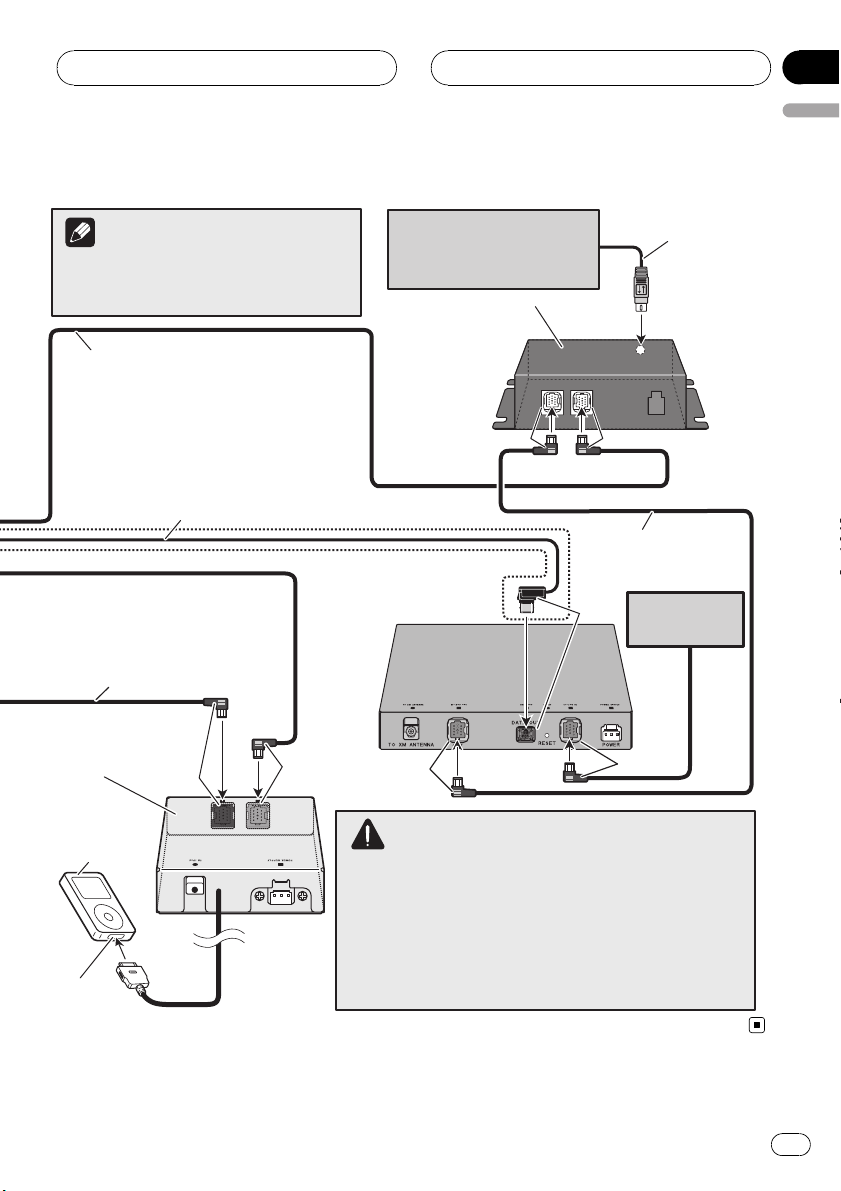
Note
The XM tuner and SiriusConnect universal
tuner will not receive their service when you
drive outside of their coverage area.
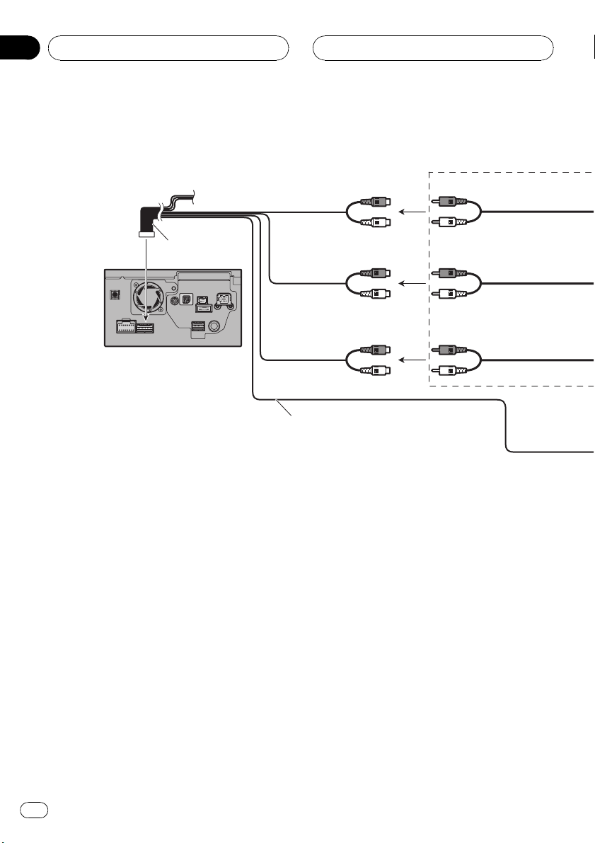
IP-BUS cable
(supplied with SIRIUS BUS INTERFACE)
XM DATA cable
(supplied with hide-away XM tuner)
* When combining this navigation system with
GEX-P10XMT (sold separately), this connection
must be required.
* When installing the XM tuner in the trunk, etc.,
the extension cable (e.g. CD-600DC)
(sold separately) is required.
IP-BUS cable
(supplied with iPod adapter)
Interface adapter for iPod
(e.g. CD-IB100II)
(sold separately)
Black
Blue
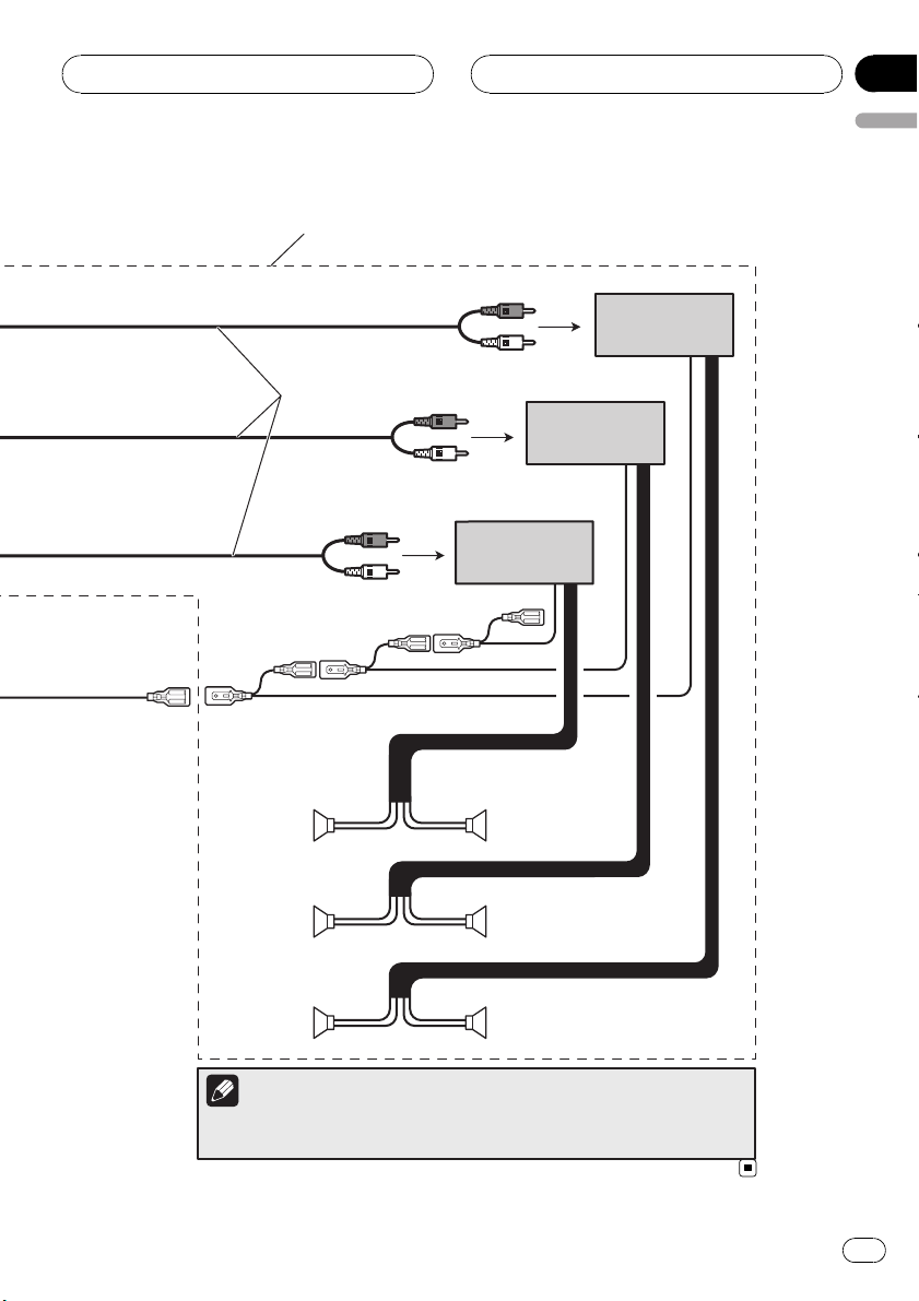
“SiriusConnect universal tuner”
or “SIRIUS Dock and play radio
with SiriusConnect vehicle kit”
(sold separately)
SIRIUS BUS INTERFACE
(e.g. CD-SB10)
(sold separately)
Hide-away XM tuner
(e.g. GEX-P10XMT)
(sold separately)
Black
Blue
SiriusConnect Cable
(sold separately)
Black
IP-BUS cable
(supplied with hide-away
XM tuner)
Multi-CD player
Black
(sold separately)
Blue
iPod® with
Dock connector
Dock
connector port
WARNING
· To avoid the risk of accident and the potential violation of
applicable laws, this product should never be used while the
vehicle is being driven except for navigation purposes. And,
also Rear Displays should not be in a location where it is a
visible distraction to the driver.
· In some countries or states, the viewing of images on a display
inside a vehicle even by persons other than the driver may be
illegal. Where such regulations apply they must be obeyed and
this product´s video source or TV features should not be used.
En
9
Section
02
Connecting the System
Connecting the multi-channel processor
Note
When Pioneer multi-channel processor (sold separately) is
connected to this navigation system, make sure the “5.1 Ch
Setup” mode is activated. Please find the correct setting by
referring to the operation manual of the navigation system.
Secure the connector using the screw
supplied with multi-channel processor.
Blue
Blue
(GUIDE SP OUT)
The navigation unit
Light Gray
(DIGITAL OUTPUT)
Guide speaker
(e.g. CD-TS37GP)
(sold separately)
10
RCA
connector 1
En
Yellow/black (GUIDE ON)
RCA connector 2
Black
20 cm (7-7/8 in.)
Optical cable connection box
(supplied with multi-channel processor)
23 cm (9 in.)
When combining this navigation unit with the
multi-channel processor system, connect this
lead to yellow/black lead on the multi-channel
processor controller unit. In this way, when the
mute signal is output from this navigation
system, the audio volume is automatically
muted or attenuated.
Connecting the System
Note
Be sure that “DIGITAL OUTPUT” of this navigation system is connected to
“OPT.IN 2” of the multi-channel processor via optical cable.
Black
IP-BUS cable
Multi-channel processor
(e.g. DEQ-P8000)
(sold separately)
(supplied with multi-channel
processor)
Section
02
English
OPT.IN 2
Blue
Optical cable
(supplied with
multi-channel processor)
RCA cable
(supplied with
multi-channel
processor)
Subwoofer output
or non-fading output
(SUBWOOFER OUTPUT or
NON-FADING OUTPUT)
Multi-channel
processor
controller unit
(e.g. AXM-P8000)
(Hide away unit)
Multi-channel processor
controller unit
(e.g. AXM-P8000)
(Display unit)
RCA cable (supplied with multi-channel
processor controller unit)
Blue
En
11
Section
02
Connecting the System
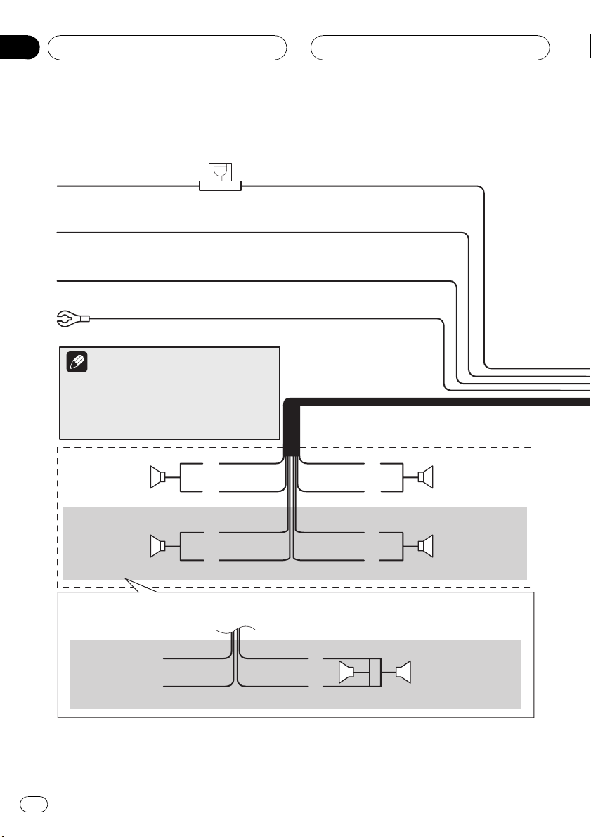
Connecting the power cord (1)
Fuse (10 A)
Yellow
To terminal always supplied with power
regardless of ignition switch position.
Red
To electric terminal controlled by ignition
switch (12 V DC) ON/OFF.
Orange/white
To lighting switch terminal.
Black (ground)
To vehicle (metal) body.
Note
When a subwoofer is connected to this navigation
system instead of a rear speaker, change the rear
output setting in the Initial Setting. (Refer to the
operation manual.) The subwoofer output of this
navigation system is monaural.
With a 2 speaker system, do not connect anything to
the speaker leads that are not connected to speakers.
12
Left Right
Rear speaker or
Subwoofer (4 Ω)
When using a subwoofer of 70 W (2
navigation system. Do not connect anything with green and green/black leads.
Not used.
En
Green
Green/black
White
White/black
Green
Green/black
Ω
), be sure to connect with violet and violet/black leads of this
Violet
Violet/black
Gray
Gray/black
Violet
Violet/black
Front speakerFront speaker
Rear speaker or
Subwoofer (4 Ω)
Subwoofer (4 Ω)
2
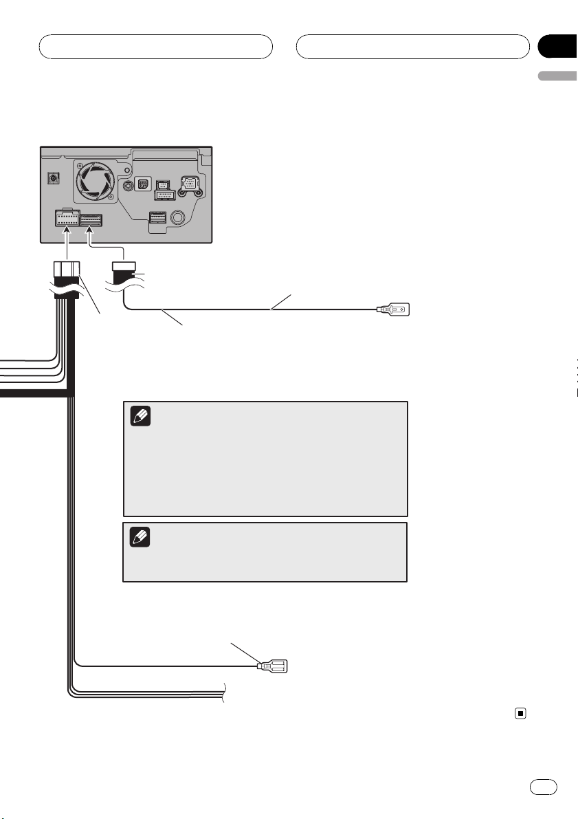
Connecting the System
The navigation unit
RCA connector 1
Section
02
English
16 cm (6-1/4 in.)
Power cord
Yellow/black
If you use equipment with a mute
function, connect that equipment to
the Audio Mute lead. If not, keep the
Audio Mute lead free of any
connections.
Note
Audio source will be set to mute or attenuate, while the following
sounds will not be muted or attenuated. For details, see the
operation manual.
—
voice guidance of the navigation
—
incoming Ringtone and incoming voice of the cellular phone
that is connected to this navigation system via Bluetooth
wireless technology
Note
The antenna will automatically retract or turn off, yet the timing
varies depending on the setting.
Blue
To auto-antenna relay control terminal.
If the vehicle has a glass antenna, connect to the antenna
booster power control terminal (max. 300 mA 12 V DC).
En
13
Section
02
Connecting the System
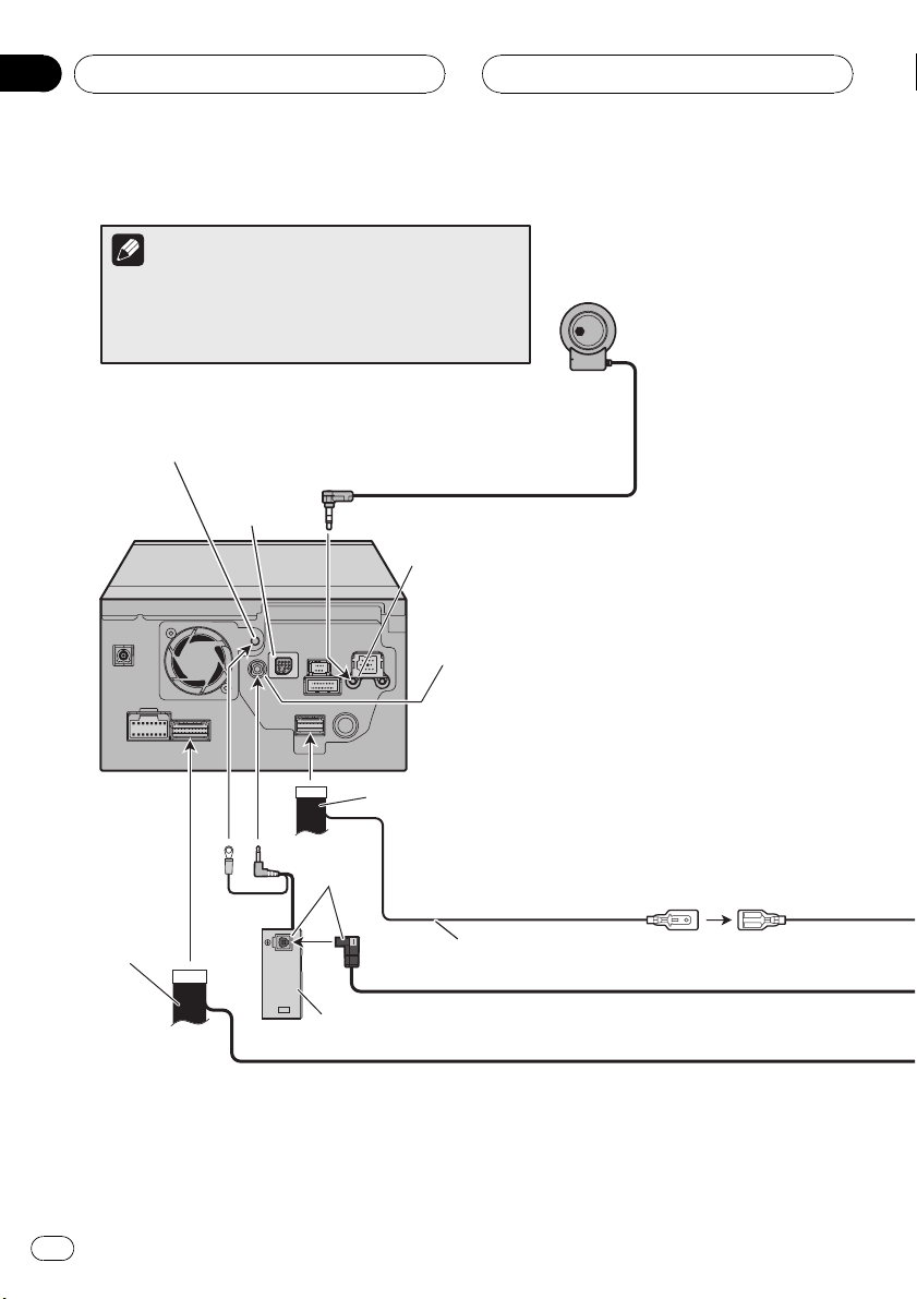
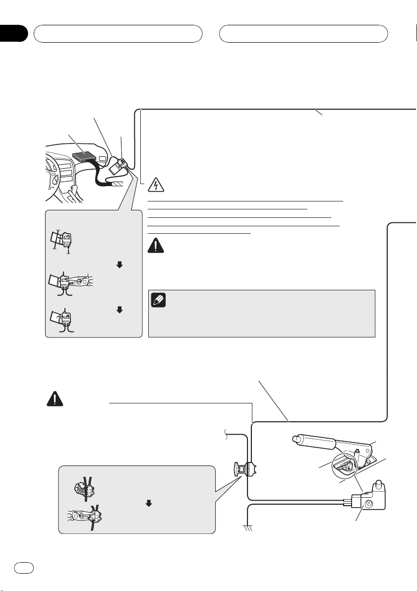
Connecting the power cord (2)
Speed detection circuit lead
Vehicle injection
computer
Connector
Pink (CAR SPEED SIGNAL INPUT)
The mobile navigation system is connected here to detect the
distance the vehicle travels. Always connect the vehicle´s speed
detection circuit or the ND-PG1 speed pulse generator, sold
separately. Failure to make this connection will increase errors in
the location display.
WARNING
IMPROPER CONNECTION MAY RESULT IN SERIOUS DAMAGE
OR INJURY INCLUDING ELECTRICAL SHOCK, AND
Connection method
Pass the extension
cord and the lead for
the speed detection
circuit through this
hole.
Clamp firmly
with needlenosed pliers.
INTERFERENCE WITH THE OPERATION OF THE VEHICLE´S
ANTILOCK BRAKING SYSTEM, AUTOMATIC TRANSMISSION
AND SPEEDMETER INDICATION.
CAUTION
· It is strongly suggested that the speed pulse wire be connected for
accuracy of navigation and better performance of interlock.
· If the speed pulse wire is unavailable for some reason, it is
recommended that the pulse generator (ND-PG1) be used.
Note
Close the cover.
Light green
Used to detect the ON/OFF status of the parking brake. This lead must be
connected to the power supply side of the parking brake switch.
If this connection is made incorrectly or omitted, certain functions
of your navigation system will be unusable.
The position of the speed detection circuit and the position of the
parking brake switch vary depending on the vehicle model. For details,
consult your authorized Pioneer dealer or an installation professional.
5 m (16 ft. 5 in.)
WARNING
LIGHT GREEN LEAD AT POWER CONNECTOR IS
DESIGNED TO DETECT PARKED STATUS AND MUST
BE CONNECTED TO THE POWER SUPPLY SIDE OF THE
PARKING BRAKE SWITCH. IMPROPER CONNECTION
OR USE OF THIS LEAD MAY VIOLATE APPLICABLE
LAW AND MAY RESULT IN SERIOUS INJURY OR
DAMAGE.
Connection method
Clamp the parking brake switch
power supply side lead.
Clamp firmly with needle-nosed
pliers.
14
En
Power supply side
Ground side
Parking brake switch
Connecting the System
Section
02
English
Extension lead (for speed signal)
Violet/white (REVERSEGEAR SIGNAL INPUT)
This is connected so that the navigation system
can detect whether the vehicle is moving
forwards or backwards. Connect the violet/white
lead to the lead whose voltage changes when
the shift lever is put in reverse. Unless
connected, the sensor may not detect your
vehicle traveling forward/backward properly,
and thus the position of your vehicle detected by
the sensor may be misaligned from the actual
position.
Note
When you use the ND-PG1 speed pulse
generator (sold separately), please make sure to
connect this lead. When you use a rear view
camera, please make sure to connect this lead.
Otherwise you cannot switch to rear view camera
picture.
The navigation unit
Power cord
Connection method
Clamp the backup
light lead.
Clamp firmly with
needle-nosed
pliers.
CAUTION
Be sure to use only the supplied extension lead. Use of another
lead could cause fire, smoke and/or damage this navigation
system.
Extension lead
(for reverse signal)
Check the position of your
vehicle´s backup light (the one
that lights up when the shift lever
is in reverse [R]) and find the
backup light lead in the trunk.
Fuse resistor
5 m (16 ft. 5 in.)
Backup
light lead
En
15
Section
02
Connecting the System
When connecting to separately sold power amp
Subwoofer output or non-fading output
(SUBWOOFER OUTPUT or NONFADING OUTPUT)
23 cm (9 in.)
RCA connector 1
The navigation unit
Rear output
(REAR OUTPUT)
15 cm (5-7/8 in.)
Front output
(FRONT OUTPUT)
15 cm (5-7/8 in.)
15 cm (5-7/8 in.)
Blue/white
To system control terminal of the power amp
(max. 300 mA 12 V DC).
16
En
Connecting the System
Perform these connections when using the
optional amplifier.
RCA cables
(sold separately)
Section
02
English
Power amp
(sold separately)
Power amp
(sold separately)
Power amp
(sold separately)
System remote control
Left Right
Front speaker
Rear speaker
Subwoofer
Front speaker
Rear speaker
Subwoofer
Note
You can change the RCA output of the subwoofer depending on your subwoofer
system. (Refer to the operation manual.)
En
17
Section
02
Connecting the System
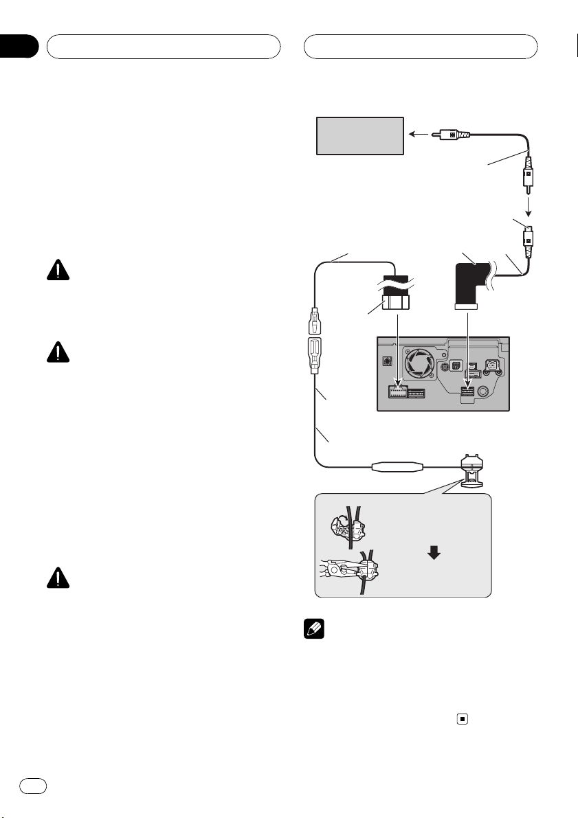
When connecting a rear view
camera
When this product is used with a rear view
camera, it is possible to automatically switch
from the video to rear view image when the
gear shift is moved to REVERSE (R). Rear
View mode also allows you to check what is
behind you while driving.
WARNING
USE INPUT ONLY FOR REVERSE OR MIRROR
IMAGE REAR VIEW CAMERA. OTHER USE MAY
RESULT IN INJURY OR DAMAGE.
CAUTION
! The screen image may appear reversed.
! The rear view camera function is to use this
product as an aid to keep an eye on trailers, or
backing into a tight parking spot. Do not use
this function for entertainment purposes.
! The object in rear view may appear closer or
more distant than in reality.
! Please note that the edges of the rear view
camera images may differ slightly according
to whether full screen images are displayed
when backing, and whether the images are
used for checking the rear when the vehicle is
moving forward.
CAUTION
Be sure to use only the supplied extension
lead. Use of another lead could cause fire,
smoke and/or damage this navigation system.
Rear view
camera
Violet/white
Power cord
5 m
(16 ft. 5 in.)
Extension lead (for reverse signal)
Fuse resistor
Connection method
To video output
RCA cable
(sold separately)
Brown
(REAR VIEW CAMERA IN)
RCA connector 2
The navigation unit
Clamp the reversing
lamp lead.
Clamp firmly with
needle-nosed pliers.
20 cm
(7-7/8 in.)
Notes
! It is necessary to set [Camera Input]in[Sys-
tem Settings]to[On] when connecting the
rear view camera. (For details, refer to the operation manual.)
! Connect to the rear view camera. Do not con-
nect to any other equipment.
18
En
 Loading...