

Page 1

19820-6NL-07
PNOZ X8P
4
D Betriebsanleitung
4
GB Operating instructions
4
F Manuel d'utilisation
4 E Instrucciones de uso
4 I Istruzioni per l`uso
4 NL Gebruiksaanwijzing
Sicherheitsbestimmungen
• Das Gerät darf nur von Personen
installiert und in Betrieb genommen
werden, die mit dieser Betriebsanleitung
und den geltenden Vorschriften über
Arbeitssicherheit und Unfallverhütung
vertraut sind. Beachten Sie die VDEsowie die örtlichen Vorschriften, insbesondere hinsichtlich Schutzmaßnahmen.
• Beim Transport, der Lagerung und im
Betrieb die Bedingungen nach EN 600682-78 einhalten (s. technische Daten).
• Durch Öffnen des Gehäuses oder
eigenmächtige Umbauten erlischt jegliche
Gewährleistung.
• Montieren Sie das Gerät in einen
Schaltschrank; Staub und Feuchtigkeit
können sonst zu Beeinträchtigungen der
Funktionen führen.
• Sorgen Sie an allen Ausgangskontakten
bei kapazitiven und induktiven Lasten für
eine ausreichende Schutzbeschaltung.
Bestimmungsgemäße Verwendung
Das Sicherheitsschaltgerät dient dem
sicherheitsgerichteten Unterbrechen eines
Sicherheitsstromkreises. Das Sicherheitsschaltgerät erfüllt Forderungen der
EN 60947-5-1, EN 60204-1 und
VDE 0113-1 und darf eingesetzt werden in
Anwendungen mit
• Not-Halt-Tastern
• Schutztüren
• Lichtschranken
Das Gerät ist für die Absicherung von
berührungslosen Verdeckungen geeignet,
da ein dynamischer Start möglich ist.
Safety Regulations
• The unit may only be installed and
operated by personnel who are familiar
with both these instructions and the
current regulations for safety at work and
accident prevention. Follow VDE and
local regulations especially as regards
preventative measures.
• Transport, storage and operating
conditions should all conform to
EN 60068-2-78.
• Any guarantee is void following opening
of the housing or unauthorised
modifications.
• The unit should be panel mounted,
otherwise dampness or dust could lead to
function impairment.
• Adequate protection must be provided on
all output contacts especially with
capacitive and inductive loads.
Authorised Applications
The safety relay provides a safety-related
interruption of a safety curcuit. The safety
relay meets the requirements of EN 609475-1, EN 60204-1 and VDE 0113-1 and may
be used in applications with
• E-STOP pushbuttons
• Safety gates
• Light barriers
The device is suitable for non-contact
barriers (e.g. light curtains) because a
dynamic start is possible.
Conseils préliminaires
• La mise en oeuvre de l’appareil doit être
effectuée par une personne spécialisée
en installations électriques, en tenant
compte des prescriptions des différentes
normes applicables (NF, EN, VDE...)
notamment au niveau des risques
encourus en cas de défaillance de
l’équipement électrique.
• Respecter les exigences de la norme
EN 60068-2-78 lors du transport, du
stockage et de l'utilisation de l'appareil.
• L’ouverture de l’appareil ou sa modification annule automatiquement la
garantie.
• L’appareil doit être monté dans une armoire; l’humidité et la poussière pouvant
entraîner des aléas de fonctionnement.
• Vérifiez que le pouvoir de coupure des
contacts de sortie est suffisant en cas de
circuits capacitifs ou inductifs.
Domaines d’utilisation
Le bloc logique de sécurité sert à
interrompre en toute sécurité un circuit de
sécurité. Le bloc logique de sécurité satisfait
aux exigences des normes EN 60947-5-1,
EN 60204-1 et VDE 0113-1 et peut être
utilisé dans des applications avec des
• poussoirs d'arrêt d'urgence
• protecteurs mobiles
• barrières immatérielles
L'appareil est adapté à la surveillance de
barrières immatérielles car une validation
dynamique est possible (surveillance du
circuit de réarmement).
Gerätebeschreibung
Das Sicherheitsschaltgerät PNOZ X8P ist in
einem P-99-Gehäuse untergebracht. Es
stehen verschiedene Varianten für den
Betrieb mit Wechselspannung und eine
Variante für den Betrieb mit Gleichspannung
zur Verfügung.
Merkmale:
• Relaisausgänge: 3 Sicherheitskontakte
(Schließer) und 2 Hilfskontakte (Öffner),
zwangsgeführt
• Anschlussmöglichkeit für Not-Halt-Taster,
Schutztürgrenztaster und Starttaster
• Statusanzeige
• Rückführkreis zur Überwachung externer
Schütze
• 2 Halbleiterausgänge melden Betriebsbereitschaft bzw. Störung bei Erd- oder
Querschluss
Das Schaltgerät erfüllt folgende Sicherheitsanforderungen:
• Schaltung ist redundant mit Selbstüberwachung aufgebaut (EN 954-1 Kat. 4).
• Sicherheitseinrichtung bleibt auch bei
Ausfall eines Bauteils wirksam.
• Bei jedem Ein-Aus-Zyklus der Maschine
wird automatisch überprüft, ob die Relais
der Sicherheitseinrichtung richtig öffnen
und schließen.
Description
The Safety Relay PNOZ X8P is enclosed in
a 45 mm P-99 housing. There are different
versions available for AC operation and one
for DC operation.
Features:
• Relay outputs: 3 safety contacts (N/O)
and 2 auxiliary contacts (N/C), positiveguided.
• Connections for Emergency Stop button,
safety sate limit switch and reset button.
• Status indicators.
• Feedback control loop for monitoring of
external contactors/relays.
• 2 semiconductor outputs: one shows
ready for operation and one shows an
earth fault or shorts across the input
channels.
The relay complies with the following safety
requirements:
• The circuit is redundant with built-in selfmonitoring (EN 954-1 Category 4).
• The safety function remains effective in
the case of a component failure.
• The correct opening and closing of the
safety function relays is tested
automatically in each on-off cycle.
Description de l’appareil
Inséré dans un boîtier P-99, le bloc logique
de sécurité PNOZ X8P est disponible en
versions différentes pour les tensions de
commandes alternatives et 1 version pour
les tensions continues.
Particularités :
• Sorties disponibles : 3 contacts à
fermeture de sécurité et 2 contacts à
ouverture pour signalisation
• Bornes de raccordement pour poussoirs
AU, détecteurs de position et poussoir de
validation
• LEDs de visualisation
• Boucle de retour pour l’auto-contrôle des
contacteurs externes
• 2 sorties statiquesd'information (relais en
position travail et défaut court-circuit ou
mise à la terre)
Le relais PNOZ X8P répond aux exigences
suivantes :
• conception redondante avec autosurveillance (selon EN 954-1 cat. 4)
• sécurité garantie même en cas de
défaillance d’un composant
• test cyclique (ouverture/fermeture des
relais internes) à chaque cycle Marche/
Arrêt de la machine
- 1 -
Page 2
• AC-Schaltgeräte haben einen kurzschlussfesten Netztransformator. DC-Schaltgeräte
besitzen eine elektronische Sicherung.
• AC relays are fitted with a short-circuit
proof power transformer. DC relays have
an electronic fuse.
• transfo. interne protégé contre les c.c
(relais en AC)
• fusible électronique (relais en DC)
Funktionsbeschreibung
Das Schaltgerät PNOZ X8P dient dem
sicherheitsgerichteten Unterbrechen eines
Sicherheitsstromkreises. Nach Anlegen der
Versorgungsspannung leuchtet die LED
"Power". Das Gerät ist betriebsbereit, wenn
der Rückführkreis Y1-Y2 und Startkreis
S33-S34 geschlossen sind.
• Eingangskreis geschlossen (z. B. NotHalt-Taster nicht betätigt):
Die LED "CH. 1 IN" und CH. 2 IN"
leuchten. Relais K1 und K2 gehen in
Wirkstellung und halten sich selbst. Die
Statusanzeigen für "CH. 1" und "CH. 2"
leuchten. Durch Öffnen der Öffnerkontakte von K1 und K2 geht K3 nach
Ablauf der Rückfallverzögerung von
180 ms in Ruhestellung. Die Sicherheitskontakte (13-14/23-24/33-34) sind
geschlossen, die Hilfskontakte (41-42/51-
52) sind geöffnet.
• Eingangskreis wird geöffnet (z. B. Not-HaltTaster betätigt):
Die Statusanzeige für "CH. 1 IN" und
"CH. 2 IN" erlischt. Relais K1 und K2 fallen
in die Ruhestellung zurück. Die Statusanzeige für "CH. 1" und "CH. 2" erlischt. Die
Sicherheitskontakte (13-14/23-24/ 33-34)
werden redundant geöffnet, die Hilfskontakte (41-42/51-52) geschlossen.
Start mit Überwachung (Taster im Startkreis
und Y1-S37 geschlossen)
Bei Betätigen des Starttasters zieht Relais K3
an und hält sich selbst. Die LED "Start"
leuchtet. Erst nach Loslassen des Starttasters
ist das Gerät betriebsbereit. Relais K3 fällt ab
und die LED "Start" leuchtet nicht mehr.
Function Description
The relay PNOZ X8P provides a safetyoriented interruption of a safety circuit.
When the operating voltage is supplied the
LED "Power" is illuminated. The unit is
ready for operation, when the Feedback
control loop Y1-Y2 and the reset circuit S33S34 are closed.
• Input Circuit closed (e.g. the Emergency
Stop button is not pressed):
The LED "CH. 1 IN" and "CH. 2 IN" are
illuminated. Relays K1and K2 energise
and retain themselves. The status
indicators for "CH. 1" and "CH. 2"
illuminate. When the N/C auxiliary
contacts K1 and K2 open, K3 goes into
rest condition after a delay-on de-energisation period of 180 ms.The safety contacts (13-14/23-24/33-34) are closed, the
auxiliary contacts (41-42/51-52) are open.
• Input Circuit is opened (e.g. Emergency
Stop is pressed)
The status indicators for "CH.1 IN" and
"CH. 2 IN" go out. Relays K1 and K2 deenergise. The status indicators for "CH.1"
and "CH.2" go out. The safety contacts
(13-14/23-24/33-34) will be opened
(redundant), the auxiliary contacts (41-42/
51-52) close.
Reset with monitoring (Button in reset
circuit and Y1-S37 linked)
By pressing the reset button, relay K3
energises and retains itself. The LED "Start"
illuminates. Only after releasing the reset
button is the unit ready for operation. Relay
K3 de-energises and the LED "Start" is no
longer illuminated.
Description du fonctionnement
Le relais PNOZ X8P assure de façon sure,
l’ouverture d’un circuit de sécurité. A la mise
sous tension du relais (A1-A2), la LED
"Power" s'allume. Le relais est activé si la
boucle de retour Y1-Y2 et le circuit de
réarmement S33-S34 sont fermés.
• Circuits d'entrée fermés (poussoir AU non
actionné) :
Les LEDs "CH. 1 IN" et "CH.2 IN" sont
allumées. L'ouverture des contacts K1 et
K2 coupe l'alimentation de K3. Ce dernier
passe en position repos au bout d'une
temporisation d'env. 180 ms. Les relais
K1 et K2 passent en position travail et
s'auto-maintiennent. Les LEDs "CH.1" et
CH.2" s'allument. Les contacts de
sécurité (13-14/23-24/33-34) sont fermés
et les contacts d'info. (41-42/51-52) sont
ouvert.
• Circuits d'entrée ouverts (poussoir AU
actionné) :
Les LEDs "CH.1 IN" et "CH.2 IN" s'éteingnent. Les relais K1 et K2 retombent. Les
LEDs "CH.1" et "CH.2" s'éteingnent. Les
contacts de sécurité (13-14/23-24/33-34)
s'ouvrent et les contacts d'info. (
51-52
) se ferment.
Surveillance du poussoir de réarmement
(pontage des bornes S1-Y37)
Une action sur le poussoir de réarmement
fait monter le relais K3 qui s'auto-maintient.
La LED "Start" est allumée. Le PNOZ X9
n'est activé qu'au relâchement du poussoir
de réarmement. Le relais K3 retombe et la
LED "Start" s'éteint.
41-42/
Y31
Y35
Y32
Y30
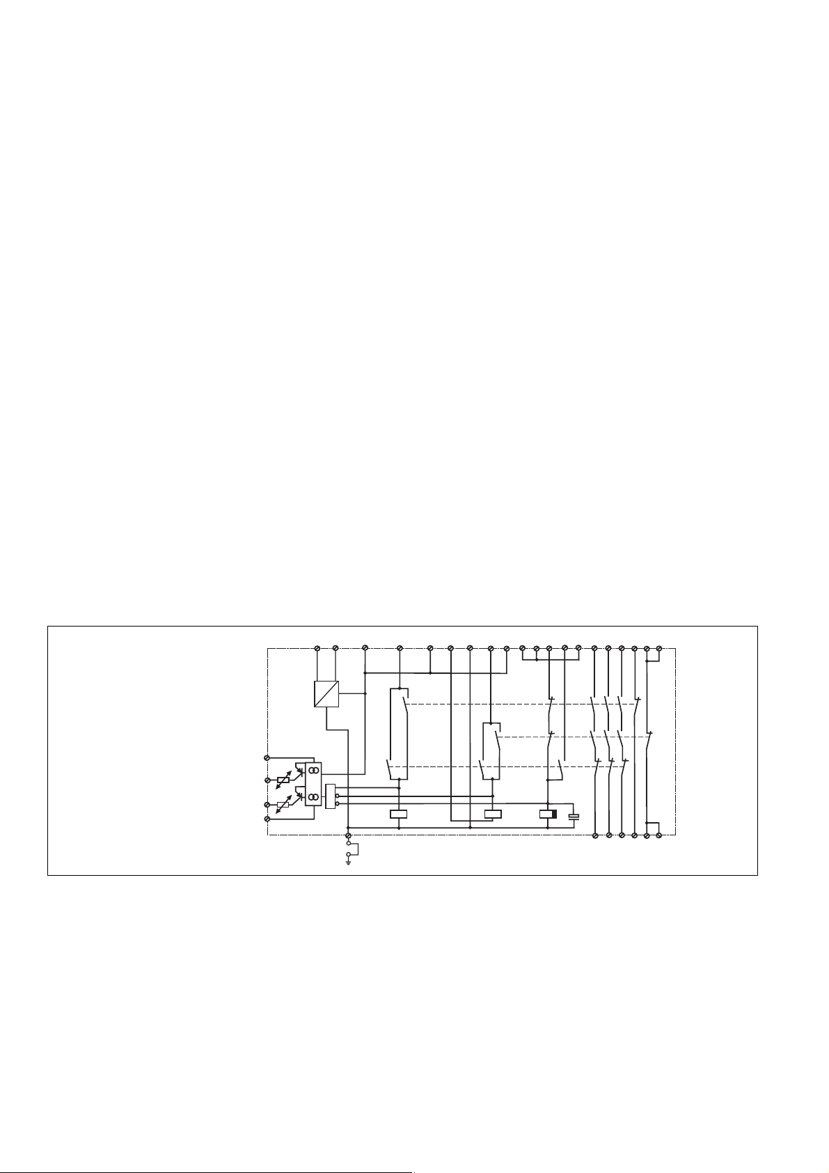
Fig. 1: Innenschaltbild/
Internal Wiring Diagram/
Schéma de principe
Halbleiterausgänge
Der Halbleiterausgang Y35 leitet, wenn die
Versorgungsspannung anliegt und die
interne Sicherung nicht ausgelöst hat.
Der Halbleiterausgang Y32 leitet, wenn die
Relais K1 und K2 in Wirkstellung sind. Er
sperrt, wenn die Relais in Ruhestellung
sind.
Betriebsarten:
• Einkanaliger Betrieb:
Eingangsbeschaltung nach VDE 0113
Teil 1 und EN 60204-1, keine Redundanz
im Eingangskreis, Erdschlüsse im
Tasterkreis werden erkannt.
A1(L+) A2(L-)
~
_
24 VDC ext.
0 V ext.
S11
+
=
&
K1
Semi-conductor outputs
The semi-conductor Y35 conducts when the
operating voltage is applied and the internal
fusing is healthy. The semi-conductor Y32
conducts if the relays K1 and K2 are
energised. Y32 switches off when the relays
de-energise to rest position
Operating Modes
• Single-channel operation: Input wiring
according to VDE 0113 part 1 and
EN 60204-1, no redundancy in the input
circuit. Earth faults are detected in the
emergency stop circuit.
S21 Y1
S34
K2
K3
41
51
S37
Y1S11
K1
K2
K3
13 23 33
14 24 34
Y2S33S22S12 S52
51
42
52
52
Sorties statiques
La sortie statique Y35 est passante si la
tension d'alimentation est présente et si le
fusible électronique n'a pas déclenché.
La sortie statique Y32 est passante si les
relais K1 et K2 sont en position travail. Elle
est bloquée si les relais sont en position
repos.
Modes de fonctionnement
• Commande par 1 canal : conforme aux
prescriptions de la EN 60204/1, pas de
redondance dans le circuit d’entrée. La
mise à la terre du circuit d’entrée est
détectée
- 2 -
Page 3

• Zweikanaliger Betrieb: redundanter
Eingangskreis, Erdschlüsse im Tasterkreis und Querschlüsse zwischen den
Tasterkontakten werden erkannt.
• Automatischer Start: Gerät ist aktiv,
sobald Eingangskreis geschlossen ist.
• Manueller Start: Gerät ist erst dann aktiv,
wenn ein Starttaster betätigt wird.
• Manueller Start mit Überwachung: Gerät
ist erst aktiv, wenn der Starttaster betätigt
und wieder losgelassen wurde.
• Kontaktvervielfachung und -verstärkung
durch Anschluss von externen Schützen.
• Two-channel operation: Redundancy in
the input circuit. Earth faults in the
Emergency Stop circuit and shorts across
the emergency stop push button are also
detected.
• Automatic reset: Unit is active as soon as
the input circuit is closed.
• Manual reset: Unit is only active when a
reset button has been pressed.
• Manual reset with monitoring: Unit is only
activated, when the reset button ist
pressed and then released.
• Increase in the number of available
contacts by connection of external
contactors/relays.
• Commande par 2 canaux: circuit d’entrée
redondant. La mise à la terre et les
courts-circuits entre les contacts sont
détectées.
• Réarmement automatique : le relais est
activé dès la fermeture des canaux
d’entrée.
• Réarmement manuel : le relais n’est
activé qu’après une impulsion sur un
poussoir de validation.
• Surveillance de circuit de réarmement :
le relais n'est activé qu'après le
relâchement du poussoir de validation.
• Augmentation du nombre de contacts ou
du pouvoir de coupure par l’utilisation de
contacteurs externes.
Montage
Das Sicherheitsschaltgerät muss in einen
Schaltschrank mit einer Schutzart von mind.
IP54 eingebaut werden. Zur Befestigung auf
einer Normschiene dient ein Rastelement
auf der Rückseite des Geräts.
Inbetriebnahme
Beachten Sie bei der Inbetriebnahme:
• Auslieferungszustand: Brücke zwischen
Y1-Y2 (Rückführkreis)
• Nur die Ausgangskontakte 13-14/23-24/
33-34 sind Sicherheitskontakte. Ausgangskontakte 41-42/51-52 sind Hilfskontakte (z. B. für Anzeige).
• Vor die Ausgangskontakte eine
Sicherung (10 A flink oder 6 A träge)
schalten, um das Verschweißen der
Kontakte zu verhindern.
• Berechnung der max. Leitungslänge I
R
lmax
=
I
max
Rl / km
R
= max. Gesamtleitungswiderstand
lmax
(s. technische Daten)
Rl /km = Leitungswiderstand/km
Da die Funktion Querschlusserkennung
nicht einfehlersicher ist, wird sie von Pilz
während der Endkontrolle geprüft. Eine
Überprüfung nach der Installation des
Geräts ist wie folgt möglich:
1. Gerät betriebsbereit (Ausgangs-
kontakte geschlossen)
2. Die Testklemmen S12-S22 zur
Querschlussprüfung kurzschließen.
3. Die Sicherung im Gerät muss auslösen
und die Ausgangskontakte öffnen.
Leitungslängen in der Größenordnung
der Maximallänge können das Auslösen
der Sicherung um bis zu 2 Minuten
verzögern.
4. Sicherung wieder zurücksetzen: den
Kurzschluss entfernen und die
Versorgungspannung für ca. 1 Minute
abschalten.
• Leitungsmaterial aus Kupferdraht mit
einer Temperaturbeständigkeit von
60/75 °C verwenden.
• Sorgen Sie beim Anschluss von magnetisch wirkenden, auf Reedkontakten
basierenden Näherungsschaltern dafür,
dass der max. Einschaltspitzenstrom (am
Eingangskreis) den Näherungsschalter
nicht überlastet.
• Angaben im Kapitel „Technische Daten“
unbedingt einhalten.
max
Installation
The safety relay must be panel mounted
(min. IP54). There is a notch on the rear of
the unit for DIN-Rail attachment.
Operation
Please note for operation:
• Unit delivered with a bridge between Y1Y2 (Feedback Control Loop)
• Only the output contacts 13-14/23-24/3334 are safety contacts. Output contact 4142/51-52 are auxiliary contacts (e.g. for
signalling).
• To prevent a welding together of the
contacts, a fuse (10 A quick/6 A slow
acting) must be connected before the
output contacts.
• Calculate the max. Cable runs I
:
R
lmax
=
I
max
Rl / km
R
= max. overall cable resistance (see
lmax
Technical details)
Rl /km = Cable resistance/km
As the function for detecting shorts across
the inputs is not failsafe, it is tested by
Pilz during the final control check.
However, a test is possible after installing
the unit and it can be carried out as
follows:
1. Unit ready for operation (output
contacts closed)
2. Short circuit the test (connection)
terminals S12-S22 for detecting shorts
across the inputs
3. The unit‘s fuse must be triggered and
the output contacts must open. Cable
lengths in the scale of the maximum
length can delay the fuse triggering for
up to 2 minutes.
4. Reset the fuse: remove the short circuit
and switch off the operating voltage for
approx. 1 minute.
• Use copper wiring that will withstand
60/75 °C
• When connecting magnetically operated,
reed proximity switches, ensure that the
max. peak inrush current (on the input
circuit) does not overload the proximity
switch.
• Important details in the section "Technical
Data“ should be noted and adhered to.
max
Montage
Le relais doit être monté en armoire ayant
un indice de protection mini IP54. Sa face
arrière permet un montage sur rail DIN.
Mise en oeuvre
Remarques préliminaires :
• Pontages présents à la livraison: Y1-Y2
(boucle de retour)
• Seuls les contacts 13-14,23-24/33-34
sont des contacts de sécurité. Les
contacts 41-42/51-52 sont des contacts
d’information (ex. voyant)
• Protection de contacts de sortie par
des fusibles 10 A rapides ou 6 A
normaux pour éviter leur soudage
:
• Calcular les longueurs de câblage max
I
dans le circuit d’entrée:
max
R
lmax
=
I
max
Rl / km
R
= Résistivité de câblage totale max.
lmax
(voir les caractéristiques techniques)
Rl /km = résistivité de câblage/km
La fonction de détection de court-circuit
est testé par Pilz lors du contrôle final. Un
test sur site est possible de la façon
suivante :
1. Appareil en fonction (contacts de sortie
fermés)
2. Court-circuiter les bornes de
raccordement nécessaires au test
S12-S22
3. Le fusible interne du relais doit
déclencher et les contacts de sortie
doivent s‘ouvrir. Le temps de réponse
du fuisible peut aller jusqu‘à 2 min. si
les longueurs de câblage sont proches
des valeurs maximales.
4. Réarmement du fusible : enlever le
court-circuit et couper l‘alimentation du
relais pendant au moins 1 min.
• Utiliser uniquement des fils de cablâge en
cuivre 60/75 °C.
• Lors du raccordement de détecteurs de
proximité magnétiques, basés sur des
contacts Reed, veuillez vous assurer que
le courant de crête max. à la mise sous
tension (sur le circuit d'entrée) ne
surcharge pas les détecteurs de
proximité.
• Respecter les données indiquées dans le
chap. „Caractéristiques techniques“.
- 3 -
Page 4

Ablauf:
• Versorgungsspannung: Versorgungsspannung an Klemmen A1 und A2
anlegen
• Eingangskreis:
- Einkanalig: S21-S22 und S12-S52
brücken. Öffnerkontakt von Auslöseelement an S12 und S11 anschließen.
- Zweikanalig ohne Querschlusser-
kennung: S21- S22 brücken; Öffnerkontakt von Auslöseelement an S11S12/S11-S52 anschließen.
- Zweikanalig mit Querschluss-
erkennung: S11-S52 brücken; Öffnerkontakt von Auslöseelement an S11S12/S21-S22 anschließen.
• Startkreis:
Einkanaliger Betrieb und zweikanaliger
Betrieb ohne Querschlusserkennung
(zweikanalig gegen +24 V geschaltet):
- Automatischer Start: S33-S34 brücken.
- Manueller Start: Taster an S33-S34
- Manueller Start mit Überwachung:
Taster zwischen S33-S34, Y1-S37
brücken.
Zweikanaliger Betrieb mit Querschlusserkennung:
- Automatischer Start: S12-S34 brücken.
- Manueller Start: Taster zwischen S12-
S34
- Manueller Start mit Überwachung:
Taster zwischen S12-S34, Y1-S37
brücken.
• Rückführkreis:
Brücke an Y1-Y2 oder externe Schütze
anschließen.
•
24 V Versorgungsspannung für Halbleiterausgänge: +24 V DC an Klemme Y31 und
0 V an Klemme Y30 anschließen.
Die Sicherheitskontakte sind aktiviert
(geschlossen) und die Hilfskontakte (41-42/
51-52) sind geöffnet. Die Statusanzeige für
"CH.1", "CH. 2", CH.1 IN" und "CH. 2 IN"
leuchten. Das Gerät ist betriebsbereit.
Wird der Eingangskreis geöffnet, öffnen die
Sicherheitskontakte 13-14/23-24/33-34 und
die Hilfskontakte 41-42/51-52 schließen. Die
Statusanzeige erlischt.
Wieder aktivieren
• Eingangskreis schließen.
• Bei manuellem Start ohne Überwachung
zusätzlich Taster zwischen S33 und S34
betätigen, bei manuellem Start mit
Überwachung Taster betätigen und
wieder loslassen.
Die Statusanzeigen leuchten wieder, die
Sicherheitskontakte sind geschlossen.
To operate:
• Supply operating voltage: Connect the
terminals A1 and A2 with the operating
voltage.
• Input circuit:
- Single-channel: Bridge S21-S22 and
S12-S52. Connect N/C contact from
safety switch (e.g. Emergency-Stop) to
S12 and S11.
- Two-channel without detection of shorts
across the contacts: Bridge S21 -S22.
Connect N/C contact from trigger
element to S11 - S12/S11 - S52
- Two-channel with detection of shorts
across the contacts: Bridge S11 -S52.
Connect N/C contact from trigger
element to S11 - S12/S21 - S22.
• Reset circuit:
Singel-channel operation and dualchannel operation without detection of
shorts across the contacts (dual-channel
switched against +24 VDC):
- Automatic reset: Bridge S33-S34
- Manual reset: Connect button to S33-
S34
- Manual reset with monitoring: Connect
button to S33-S34, bridge Y1-S37.
Dual-channel operation with detection of
shorts across the contacts:
- Automatic reset: Bridge S12-S34
- Manual reset: Connect button to S12-
S34
- Manual reset with monitoring: Connect
button to S12-S34, bridge Y1-S37.
• Feedback control loop:
Bridge Y1 - Y2 or connect external N/C
contacts in series from other devices.
• 24 VDC supply voltage for semiconductor output: Connect +24 VDC to
terminals Y31 and 0 VDC to Y30.
The safety contacts are activated (closed)
and the auxiliary contacts (41-42/51-52) are
open. The status indicators "CH.1", "CH.2",
"CH.1 IN" and "CH.2 IN" are illuminated.
The unit is ready for operation. If the input
circuit is opened, the safety contacts 13-14/
23-24/33-34 open and the auxiliary contacts
41-42/51-52 close. The status indicator
goes out.
Reactivation
• Close the input circuit.
• For manual reset without monitoring,
momentary closure of the button between
S33 and S34 must be pressed; for
manual reset with monitoring, press the
button and release again.
The status indicators light up again, the
safety contacts are closed.
Mise en oeuvre :
• Tension d’alimentation: amener la tension
d’alimentation sur A1 et A2
• Circuits d’entrée:
- Commande par 1 canal : câblage du
contact à ouverture entre S11-S12,
pontage entre S21-S22 et S12-S52
- Commande par 2 canaux sans
détection de courts-circuits : câblage
des contacts à ouverture entre S11S12/S11-S52 , pontage de S21-S22
- Commande par 2 canaux avec
détection de courts-circuits : câblage
des contacts à ouverture entre S11S12/S21-S22 , pontage de S11-S52
• Circuit de réarmement:
Commande mono-canal et en 2 canaux
sans détection de courts-circuits entre les
canaux (les 2 canaux reliés an +24 V):
- Réarmement automatique: pontage des
bornes S33-S34
- Réarmement manuel: câblage d’un
poussoir sur S33-S34
- Surveillance du circuit de réarmement:
câblage d'un poussoir sur S33-S34 et
pontage des bornes Y1-S37 .
Commande en 2 canaux avec détection
de courts-circuits:
- Réarmement automatique: pontage des
bornes S12-S34
- Réarmement manuel: câblage d’un
poussoir sur S12-S34
- Surveillance du circuit de réarmement:
câblage d'un poussoir sur S12-S34 et
pontage des bornes Y1-S37.
• Boucle de retour: Pontage de Y1-Y2 ou
branchement des contacts externes
• Alimentation en 24 VCC des sorties
statiques : relier le +24 V DC à la borne
Y31 et le 0 V à la borne Y30.
Les contacts de sécurité se ferment et les
contacts d’information 41-42/51-52
s’ouvrent. Les LEDs "CH.1", "CH.2", "CH.1
IN" et "CH.2 IN" sont allumées. L’appareil
est prêt à fonctionner. Si le circuit d’entrée
est ouvert, les contacts de sécurité
retombent et les contacts d’information 4142/51-52 se ferment. Les LEDs s’éteignent.
Remise en route :
• fermer le circuit d’entrée
• en cas de réarmement manuel sans
surveillance, appuyer sur le poussoir de
validation entre S33-S34. En cas de
surveillance du circuit de réarmement,
appuyer puis relacher le poussoir de
validation.
Les affichages d'état s'allument à nouveau.
Les contacts de sécurité sont fermées.
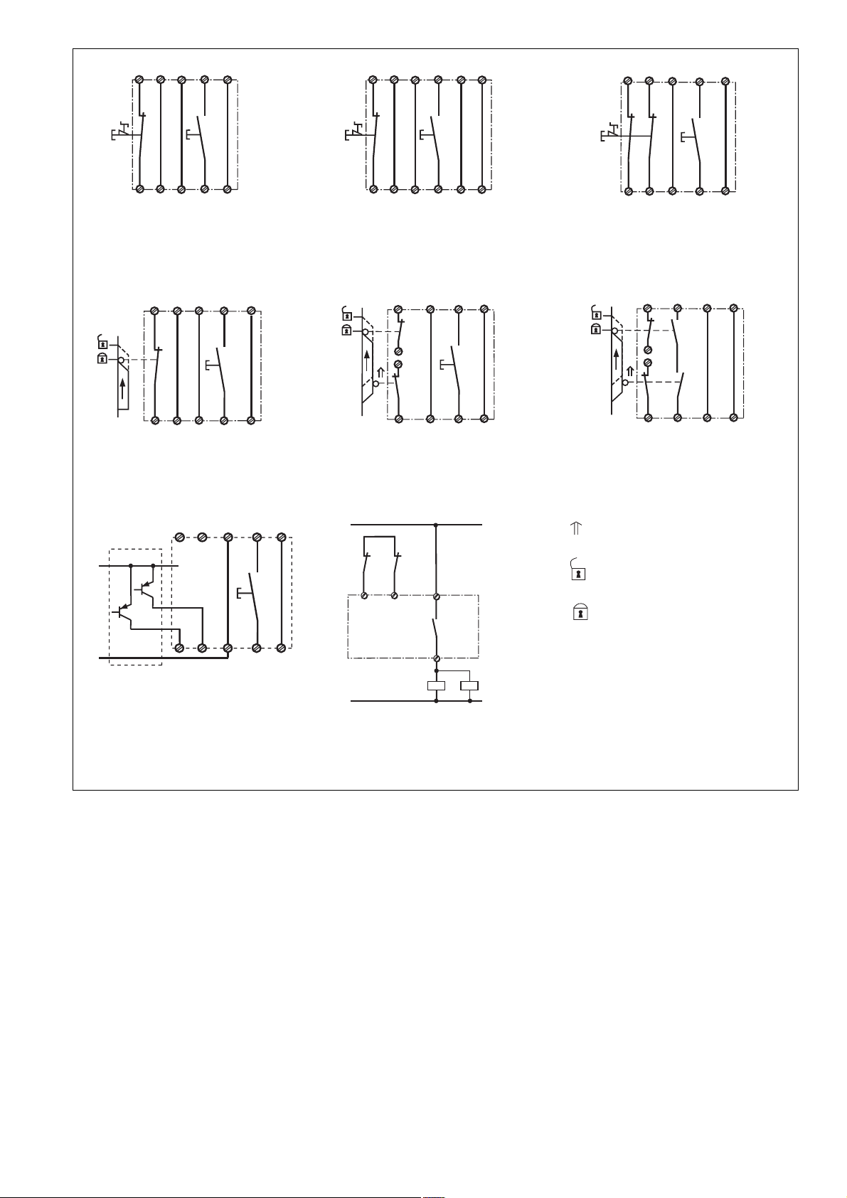
Anwendung
In Fig. 2 ... Fig. 9 sind Anschlussbeispiele
für Not-Halt-Beschaltung mit manuellem und
überwachtem Start, Schutztüransteuerungen sowie Kontaktvervielfachung durch
externe Schütze.
Fig. 7: Gleichzeitigkeit: 150 ms
Application
In Fig. 2 ... Fig. 9 are connection examples
for Emergency Stop wiring with manual and
monitored reset. Safety gate controls as well
as contact expansion via external
contactors.
Fig. 7: Simultaneity 150 ms by Safety Gate
Contol
- 4 -
Utilisation
Dans les figures 2 à 9 sont représentés les
différents cablages possibles du PNOZ X9 :
poussoirs AU avec surveillance du circuit
de réarmement, interrupteurs de position et
augmentation du nombre des contacts par
contacteurs externes.
Fig. 7: Désynchronisme: 150 ms
Page 5
S11 S12
S21
S33
Y1
S11 S12
S21
S33
Y1
S21
S11
S11
S12
Y1
S1
S12
S52
S22
S3
S34
Y2
Fig. 2: Eingangskreis einkanalig, manueller
Start/Single-channel input circuit, manual
reset/Commande par 1 canal, validation
manuelle
S3
S33
S34
Y1
Y2
S11
S12
S1
S21
S22
S12
S52
Fig. 5: Schutztürsteuerung einkanalig/
Single-channel safety gate control/
Surveillance de protecteur, commande par 1
canal
OSSD
S11
24 V DC
S3
S33S21S11
Y1
S1
S12
S52
S22
S3
S34
S37Y1Y2
Fig. 3: Eingangskreis einkanalig, überwachter Starttaster/Single-channel input circuit,
monitored reset/Commande par 1 canal,
surveillance du poussoir de validation
S12
S3
S34
Y1
Y2
S21
S12
S11
S1
S22
S11
S2
S52
Fig. 6: Schutztürsteuerung zweikanalig/Twochannel safety gate control/Surveillance de
protecteur, commande par 2 canaux
L1
K4 K5
Y1
Y2
13
S1
S22
S12
S52
S3
S34
Y2
Fig. 4: Eingangskreis zweikanalig, manueller Start/Two-channel input circuit, manual
reset/Commande par 2 canaux, validation
manuelle
S33
S34
S1
S2
S21
S22
Y1
Y2
S11
S52
S11
S12
Fig. 7: Schutztürsteuerung zweikanalig,
automatischer Start/Two channel safety
gate control,automatic reset/Surveillance de
protecteur, commande par 2 canaux,
validation automatique
betätigtes Element/Switch
activated/élément actionné
Tür nicht geschlossen/Gate
open/porte ouverte
Tür geschlossen/Gate closed/
porte fermée
GND
S12 S22 S34S52
S37
Fig. 8: Lichtschrankensteuerung, zweikanalig, Querschlusserkennung durch BWS,
überwachter Start/Dual-channel light curtain
control, short circuit detection via ESPE,
monitored reset/Commande par 2 canaux
par barrage immatériel ,surveillance du
poussoir de validation
Fehler - Störungen
• Erdschluss bei PNOZ X8P für Wechselspannung: Die Versorgungsspannung
bricht zusammen und die Sicherheitskontakte werden geöffnet.
• Erdschluss bei PNOZ X8P für Gleichspannung: Eine elektronische Sicherung
bewirkt das Öffnen der Ausgangskontakte
bei Fehlströmen. Nach Wegfall der
Störungsursache und Abschalten der
Versorgungsspannung für ca. 1 Minute ist
das Gerät wieder betriebsbereit.
• Fehlfunktionen der Kontakte: Bei
verschweißten Kontakten ist nach Öffnen
des Eingangskreises keine neue Aktivierung möglich.
• LED "Power" leuchtet nicht: Kurzschluss
oder Versorgungsspannung fehlt
14
K4
K5
N
Fig. 9: Anschlussbeispiel für externe
Schütze, einkanalig/Connection example for
external contactors/relays, single-channel/
Branchement contacteurs externes,
commande par 1 canal
Faults
• Earth fault on PNOZ X8P for AC
operation: The supply voltage fails and
the safety contacts are opened.
• Earth fault on PNOZ X8P for DC
operation:
An electronic fuse causes the output
contacts to open with fault currents. Once
the cause of the fault has been removed
and operating voltage has been switched
off for approximately 1 minute, the unit
will be ready for operation.
• Contact failure: In the case of welded
contacts, no further activation is possible
following an opening of the input circuit.
• LED "Power" is not illuminated if shortcircuit or the supply voltage is lost.
S1/S2: Not-Halt- bzw. Schutztürschalter/
Emergency Stop Button, Safety
Gate Limit Switch/Poussoir AU,
détecteurs de position
S3: Starttaster/Reset button/Poussoir de
réarmement
Erreurs - Défaillances
• Défaut de masse du PNOZ X8P (AC): la
tension d’alimentation s’effondre et les
contacts desortie s’ouvrent.
• Défaut de masse du PNOZ X8P (DC):
Un fusible électronique entraîne
l’ouverture des contacts de sortie en cas
de courant de fuite. Une fois la cause du
défaut éliminée et la tension
d’alimentation coupée pendeent environ
1 minute, l’appareil est à nouveau prêt à
fonctionner.
• Défaut de fonctionnement des contacts
de sortie: en cas de soudage d’un contact
lors de l’ouverture du circuit d’entrée, un
nouvel réarmement est impossible.
• LED "Power" éteinte: tension
d'alimentation non présente ou courtcircuit interne.
- 5 -
Page 6

Technische Daten
Technical Data
Caractéristiques techniques
Elektrische Daten
Versorgungsspannung U
B
Spannungstoleranz
Leistungsaufnahme bei U
B
Frequenzbereich
Restwelligkeit
Spannung und Strom an
Eingangskreis
UB = 24 V DC
UB = 24 ... 230 V AC
Start- und Rückführkreis
UB = 24 V DC
UB = 24 ... 230 V AC
Anzahl der Ausgangskontakte
Sicherheitskontakte (S)
Hilfskontakte (Ö)
Gebrauchskategorie nach
EN 60947-4-1
EN 60947-5-1(DC13:
6 Schaltspiele/Min.)
Kontaktmaterial
Kontaktabsicherung extern
EN 60947-5-1 (IK = 1 kA)
Schmelzsicherung flink
Schmelzsicherung träge
Sicherungsautomat
Charakteristik
Halbleiterausgänge (kurzschlussfest)
Externe Spannungsversorgung
Spannungstoleranz
Max. Gesamtleitungswiderstand R
Eingangskreise
einkanalig DC
einkanalig AC
zweikanalig ohne
Querschlusserkennung DC
zweikanalig ohne
Querschlusserkennung AC
zweikanalig mit
Querschlusserkennung DC
zweikanalig mit
Querschlusserkennung AC
Min. Eingangswiderstand im
Einschaltmoment
Sicherheitstechnische Kenndaten
der Sicherheitsausgänge
PL nach EN ISO 13849-1
Kategorie nach EN 954-1
SIL CL nach EN IEC 62061
PFH nach EN IEC 62061
SIL nach IEC 61511
PFD nach IEC 61511
tM in Jahren
Zeiten
Einschaltverzögerung
UB = 24 V DC
Automatischer Start
Automatischer Start nach Netz-Ein
Manueller Start
Überwachter Start
UB = 24 ... 230 V AC
Automatischer Start
Automatischer Start nach Netz-Ein
Manueller Start
Überwachter Start
Electrical data
Supply Voltage U
B
Voltage Tolerance
Power consumption at U
B
Frequency Range
Residual Ripple
Voltage and Current at
Input circuit
UB = 24 V DC
UB = 24 ... 230 V AC
Reset circuit and feedback loop
UB = 24 V DC
UB = 24 ... 230 V AC
Number of output contacts
Safety contacts (N/O)
Auxiliary contacts (N/C)
Utilization category in accordance with
EN 60947-4-1
EN 60947-5-1(DC13: 6 cycles/min)
Contact material
External contact fuse protection
EN 60947-5-1 (IK = 1 kA)
Blow-out fuse quick
Blow-out fuse slow
Safety cut-out
Characteristic
Semiconductor outputs (short circuitproof)
External supply voltage
Voltage tolerance
Max. overall cable resistance R
lmax
input circuits
Single-channel DC
Single-channel AC
dual-channel without detection of
shorts across the input contacts DC
dual-channel without detection of
shorts across the input contacts AC
Dual-channel with detection of
shorts across contacts DC
Dual-channel with detection of
shorts across contacts AC
Min. input resistance in the starting
torque
Safety-related characteristics of
the safety outputs
PL in accordance with
EN ISO 13849-1
Category in accordance with
EN 954-1
SIL CL in accordance with
EN IEC 62061
PFH in accordance with
EN IEC 62061
SIL in accordance with IEC 61511
PFD in accordance with IEC 61511
tM in years
Times
Switch-on delay
UB = 24 V DC
Automatic reset
Automatic reset after Power-On
Manual reset
Monitored manual reset
UB = 24 ... 230 V AC
Automatic reset
Automatic reset after Power-On
Manual reset
Monitored manual reset
Données électriques
Tension d’alimentation U
Plage de la tension d’alimentation
Consommation pour U
Fréquence
Ondulation résiduelle
Tension et courant du
Circuit d’entrée
UB = 24 V DC
UB = 24 ... 230 V AC
Circuit de réarmement et boucle de retour
UB = 24 V DC
UB = 24 ... 230 V AC
Nombre de contacts de sortie
contacts de sécurité (F)
contact d'info (O)
Catégorie d’utilisation selon
EN 60947-4-1
EN 60947-5-1(DC13:
6 manoeuvres/min)
Matériau contact
Protection des contacts externe
EN 60947-5-1 (IK = 1 kA)
Fusibles rapide
Fusibles normal
Dijoncteur
Caractéristique
Sorties statiques (protégées contre c.c.)
Tension d’alimentation externe
Plage de la tension d’alimentation
Résistance de câblage totale max.
lmax
R
circuits d'entrée
lmax
Commande par 1 canal DC
Commande par 1 canal AC
Command par 2 canaux sans
détection des courts-circuit DC
Command par 2 canaux sans
détection des courts-circuit AC
Commande par 2 canaux avec
détection des court-circuits DC
Commande par 2 canaux avec
détection des court-circuits AC
Résistance d'entrée min. au moment
de la mise en marche
Caractéristiques techniques de
sécurité des sorties de sécurité
PL selon EN ISO 13849-1
Catégorie selon EN 954-1
SIL CL selon EN IEC 62061
PFH selon EN IEC 62061
SIL selon IEC 61511
PFD selon IEC 61511
tM en années
Temporisations
Temps de réarmement
UB = 24 V DC
Réarmement automatique
Réarmement automatique après
mise sous tension
Réarmement manuel
Réarmement manuel auto-contrôlé
UB = 24 ... 230 V AC
Réarmement automatique
Réarmement automatique après
mise sous tension
Réarmement manuel
Réarmement manuel auto-contrôlé
B
AC: 24 V, 110 V, 115 V,
120 V, 230 V
DC: 24 V
-15 ... +10 %
B
AC: 6,5 VA
DC: 2,5 W
50 ... 60 Hz
DC: 160 %
24 V DC/45 mA
24 V DC/40 mA
24 V DC/50 mA
24 V DC/60 mA
3
2
AC1: 240 V/0,01 ... 8 A/
2000 VA
DC1: 24 V/0,01 ... 8 A/200 W
AC15: 230 V/5 A;
DC13: 24 V/7 A
AgSnO2+ 0,2 µm Au
10 A
6 A
24 V AC/DC: 6 A
B/C
24 V DC / 50 mA
24 V DC
-20 % - 20 %
100 Ohm
100 Ohm
200 Ohm
200 Ohm
16 Ohm
28 Ohm
89 Ohm
PL e (Cat. 4)
Cat. 4
SIL CL 3
2,31E-09
SIL 3
2,03E-06
20
typ. 160 ms, max. 200 ms
typ. 185 ms, max. 220 ms
typ. 190 ms, max. 250 ms
typ. 130 ms, max. 180 ms
typ. 175 ms, max. 220 ms
typ. 200 ms, max. 250 ms
typ. 190 ms, max. 250 ms
typ. 130 ms, max. 180 ms
- 6 -
Page 7

Rückfallverzögerung
UB = 24 V DC
bei Not-Halt
bei Netzausfall
UB = 24 ... 230 V AC
bei Not-Halt
bei Netzausfall
Wiederbereitschaftszeit bei max.
Schaltfrequenz 1/s
nach Not-Halt
nach Netzausfall
UB = 24 V DC
UB = 24 ... 230 V AC
Min. Startimpulsdauer bei
überwachtem Start
Gleichzeitigkeit Kanal 1 und 2
Überbrückung bei Spannungseinbrüchen
Umweltdaten
EMV
Schwingungen nach EN 60068-2-6
Frequenz
Amplitude
Klimabeanspruchung
Luft- und Kriechstrecken nach
EN 60947-1
Verschmutzungsgrad
Überspannungskategorie
Bemessungsisolationsspannung
Bemessungsstoßspannungs-festigkeit
Umgebungstemperatur
Lagertemperatur
Schutzart
Einbauraum (z. B. Schaltschrank)
Gehäuse
Klemmenbereich
Mechanische Daten
Gehäusematerial
Gehäuse
Front
Querschnitt des Außenleiters
(Schraubklemmen)
1 Leiter, flexibel
2 Leiter gleichen Querschnitts, flexi-
bel mit Aderendhülse, ohne
Kunststoffhülse
ohne Aderendhülse oder mit TWIN-
Aderendhülse
Querschnitt des Außenleiters
(Federkraftklemmen)
flexibel ohne Aderendhülse
Gehäuse mit Federkraftklemmen
Abisolierlänge
Klemmstellen pro Anschluss
Anzugsdrehmoment für
Schraubklemmen
Abmessungen (Schraubklemmen)
H x B x T
Abmessungen (Federkraftklemmen)
H x B x T
Einbaulage
Gewicht
UB = 24 V DC
UB = 24 ... 230 V AC
Delay-on De-Energisation
UB = 24 V DC
at E-STOP
with power failure
UB = 24 ... 230 V AC
at E-STOP
with power failure
Recovery time at max. switching
frequency 1/s
after E-STOP
after power failure
UB = 24 V DC
UB = 24 ... 230 V AC
Min. start pulse duration with a
monitored reset
Simultaneity channel 1 and 2
Supply interruption before de-energisation
Environmental data
EMC
Vibration to EN 60068-2-6
Frequency
Amplitude
Climate Suitability
Airgap Creepage in accordance with
EN 60947-1
Pollution degree
Overvoltage category
Rated insulation voltage
Rated impulse withstand voltage
Ambient temperature
Storage temperature
Protection type
Mounting (eg. panel)
Housing
Terminals
Mechanical data
Housing material
Housing
Front panel
Cable cross section (screw
terminals)
1 core, flexible
2 core, same cross section flexible
with crimp connectors, without
insulating sleeve
without crimp connectors or with
TWIN crimp connectors
Cable cross section (spring-loaded
terminals)
flexible without crimp connectors
Housing with spring-loaded terminals
Stripping length
Termination points per connection
Torque setting for screw terminals
Dimensions (screw terminals)
H x W x D
Dimensions (spring-loaded terminals)
H x W x D
Fitting Position
Weight
UB = 24 V DC
UB = 24 ... 230 V AC
Temps de retombée
UB = 24 V DC
en cas d'arrêt d'urgence
en cas de coupure d'alimentation
UB = 24 ... 230 V AC
en cas d'arrêt d'urgence
en cas de coupure d'alimentation
Temps de remise en service en cas de
fréquence de commutation max. 1/s
arrêt d'urgence
après une coupure d'alimentation
UB = 24 V DC
UB = 24 ... 230 V AC
Durée minimale de l’impulsion pour
un réarmement auto-contrôlé
Désynchronisme canal 1 et 2
Tenue aux micro-coupures
Données sur l'environnement
CEM
Vibrations selon EN 60068-2-6
Frequence
Amplitude
Conditions climatiques
Cheminement et claquage selon
EN 60947-1
Niveau d'encrassement
Catégorie de surtensions
Tension assignée d'isolement
Tension assignée de tenue aux chocs
Température d’utilisation
Température de stockage
Indice de protection
Lieu d'implantation (ex. armoire)
Boîtier
Bornes
Données mécaniques
Matériau du boîtier
Boîtier
Face avant
Capacité de raccordement
(borniers à vis)
1 conducteur souple
2 conducteurs de même diamètre
souple avec embout, sans chapeau
plastique
souple sans embout ou avec
embout TWIN
Capacité de raccordement (borniers
à ressort)
souple sans embout
Boîtier avec borniers à ressort
Longueur de dénudage
Bornes par raccordement
Couple de serrage (borniers à vis)
Dimensions (borniers à vis)
H x P x L
Dimensions (borniers à ressort)
H x L x P
Position de travail
Poids
UB = 24 V DC
UB = 24 ... 230 V AC
typ. 15 ms, max. 30 ms
typ. 100 ms, max. 200 ms
typ. 15 ms, max. 30 ms
typ. 160 ms, max. 220 ms
50 ms
180 ms
250 ms
30 ms
150 ms
35 ms
EN 60947-5-1,
EN 61000-6-2
10 ... 55 Hz
0,35 mm
EN 60068-2-78
2
III
250 V
4 kV
-10 ... + 55 °C
-40 ... +85 °C
IP54
IP40
IP20
PPO UL 94 V0
ABS UL 94 V0
0,25 ... 2,5 mm2, 24 - 12 AWG
0,25 ... 1 mm2, 24 - 16 AWG
0,20 ... 1,5 mm2, 24 - 16 AWG
0,20 ... 1,5 mm2, 24 - 16 AWG
8 mm
2
0,5 Nm
94 x 45 x 121 mm
101 x 45 x 121 mm
beliebig/any/indifférente
320 g
420 g
Es gelten die 2009-11 aktuellen Ausgaben
der Normen
The version of the standards current at
2009-11 shall apply
- 7 -
Se référer à la version des normes en vigeur
au 2009-11.
Page 8

Konventioneller thermischer Strom bei gleichzeitiger Belastung mehrerer Kontakte/Conventional thermal current
while loading several contacts/Courant thermique conventionnel en cas de charge sur plusieurs contacts (AC1, DC1)
Anzahl der Kontakte/number of contacts/nombre des contacts 3 2 1
Ith (A) pro Kontakt bei Versorgungsspannung AC/per contact
with operating voltage AC/par contact pour tension d’alimentation AC 6,0 7,3 8,0
Ith (A) pro Kontakt bei Versorgungsspannung DC/per contact
with operating voltage DC/par contact pour tension d’alimentation DC 7,0 8,0 8,0
Um ein Versagen der Geräte zu verhindern,
an allen Ausgangskontakten für eine ausreichende Funkenlöschung sorgen. Bei
kapazitiven Lasten sind eventuell auftretende
Stromspitzen zu beachten. Bei DC-Schützen
Freilaufdioden zur Funkenlöschung einsetzen,
um die Lebendauer der Schütze zu erhöhen.
To prevent failure of the unit, all output
contacts should be fused adequately. With
capacative loads, possible current peaks are
to be avoided. With DC contactors/relays
use suitable spark suppression to ensure
extended life of the contactors/relays.
Bestelldaten/Order reference/Caractéristiques
Typ/
Type/
Type
PNOZ X8P C
PNOZ X8P
PNOZ X8P C
PNOZ X8P
PNOZ X8P C
PNOZ X8P
PNOZ X8P C
PNOZ 8P
PNOZ X8P C
PNOZ X8P
PNOZ X8P C
PNOZ X8P
Merkmale/
Features/
Caractéristiques
24 V DC
24 V DC
110 V AC
110 V AC
115 V AC
115 V AC
120 V AC
120 V AC
230 V AC
230 V AC
24 V AC
24 V AC
Prévoir un dispositif d’extinction d’arc sur les
contacts de sortie pour éviter un éventuel
disfonctionnement du relais.
Tenir compte des pointes d’intensité en cas
de charge capacitive. Equiper les
contacteurs DC de diodes de roue libre .
Klemmen/
Terminals/
Borniers
Federkraftklemmen/spring-loaded terminals/
borniers à ressort
Schraubklemmen/screw terminals/borniers à vis
Federkraftklemmen/spring-loaded terminals/
borniers à ressort
Schraubklemmen/screw terminals/borniers à vis
Federkraftklemmen/spring-loaded terminals/
borniers à ressort
Schraubklemmen/screw terminals/borniers à vis
Federkraftklemmen/spring-loaded terminals/
borniers à ressort
Schraubklemmen/screw terminals/borniers à vis
Federkraftklemmen/spring-loaded terminals/
borniers à ressort
Schraubklemmen/screw terminals/borniers à vis
Federkraftklemmen/spring-loaded terminals/
borniers à ressort
Schraubklemmen/screw terminals/borniers à vis
Bestell-Nr./
Order no./
Référence
787 760
777 760
787 764
777 764
787 765
777 765
787 766
777 766
787 768
777 768
787 770
777 770
Lebensdauer der Ausgangsrelais/Service Life of Output relays/Durée de vie des relais de sortie
10
AC15: 230 V
DC1: 24 V
DC13: 24 V
1
Courant coupé (A)
Nennbetriebstrom (A)
Nominal operating current (A)
0.1
10 100 1000 10000
Schaltspielzahl x 10
Cycles x 10
Nombre de manvres x 10
AC1: 230 V
3
3
3
- 8 -
Page 9

Abmessungen in mm/Dimensions in mm/Dimensions en mm
Gehäuse mit steckbaren Schraubklemmen/
Housing with plug-in screw terminals/
Boîtier avec borniers débrochables à vis
75 (2.95")
87 (3.42")
94 (3.70")
Steckbare Klemmen abziehen
Schraubendreher in Gehäuseaussparung
hinter der Klemme ansetzen und Klemme
heraushebeln.
Klemmen nicht an den Kabeln abziehen!
121 (4.76")
Remove plug-in terminals
Insert screwdriver into the cut-out of the housing
behind the terminal and lever the terminal.
Do not remove the terminals by pulling the
cables!
45
(1.77")
Gehäuse mit steckbaren Federkraftklemmen/
Housing with plug-in spring-loaded terminals/
Boîtier avec borniers débrochables à ressort/
121 (4.76")
75 (2.95")
87 (3.42")
101 (3.98")
Démonter les borniers
débrochables
Placer un tournevis derrière les bornes et sortir le
bornier.
Ne pas retirer les borniers en tirant sur les câbles !
45
(1.77")
Abziehen der Klemmen am Beispiel einer
Schraubklemme
EG-Konformitätserklärung:
Diese(s) Produkt(e) erfüllen die Anforderungen der Richtlinie 2006/42/EG über
Maschinen des europäischen Parlaments
und des Rates.
Die vollständige EG-Konformitätserklärung
finden Sie im Internet unter www.pilz.com
Bevollmächtigter: Norbert Fröhlich,
Pilz GmbH & Co. KG, Felix-Wankel-Str. 2,
73760 Ostfildern, Deutschland
How to remove the terminals using a screw
terminal as an example
EC Declaration of Conformity:
This (these) product(s) comply with the
requirements of Directive 2006/42/EC of the
European Parliament and of the Council on
machinery.
The complete EC Declaration of Conformity
is available on the Internet at www.pilz.com
Authorised representative: Norbert Fröhlich,
Pilz GmbH & Co. KG, Felix-Wankel-Str. 2,
73760 Ostfildern, Germany
Démontage d’un bornier à vis
Déclaration de conformité CE :
Ce(s) produit(s) satisfait (satisfont) aux
exigences de la directive 2006/42/CE
relative aux machines du Parlement
Européen et du Conseil.
Vous trouverez la déclaration de conformité
CE complète sur notre site internet
www.pilz.com
Représentant : Norbert Fröhlich,
Pilz GmbH & Co. KG, Felix-Wankel-Str. 2,
73760 Ostfildern, Allemagne
- 9 -
Page 10

Technischer Support
y
0
+49 711 3409-444 +49 711 3409-444
...
In vielen Ländern sind wir durch
unsere Tochtergesellschaften und
Handelspartner vertreten.
Nähere Informationen entnehmen
Sie bitte unserer Homepage oder
nehmen Sie Kontakt mit unserem
Stammhaus auf.
Technical support
... ...
In many countries we are
represented by our subsidiaries
and sales partners.
Please refer to our Homepage
for further details or contact our
headquarters.
Assistance technique
+49 711 3409-444
Nos filiales et partenaires
commerciaux nous représentent
dans plusieurs pays.
Pour plus de renseignements,
consultez notre site internet ou
contactez notre maison mère.
- 10 -
www
www.pilz.com
Pilz GmbH & Co. KG
Felix-Wankel-Straße 2
73760 Ostfildern, German
Telephone: +49 711 3409Telefax: +49 711 3409-133
E-Mail: pilz.gmbh@pilz.de
Originalbetriebsanleitung/Original instructions/Notice originale
19820-6NL-07-2010-08 Printed in Germany
Page 11

19820-6NL-07
PNOZ X8P
4 E Instrucciones de uso
4 I Istruzioni per l`uso
4 NL Gebruiksaanwijzing
Prescripciones de seguridad
• El dispositivo tiene que ser instalado y
puesto en funcionamiento exclusivamente
por personas que estén familiarizadas, tanto
con estas instrucciones de uso como con las
prescripciones vigentes relativas a la
seguridad en el trabajo y a la prevención de
accidentes.
• Hay que observar tanto las prescripciones
VDE como las prescripciones locales,
especialmente en lo que se refiere a las
medidas de protección.
• Durante el transporte, el almacenaje y el
funcionamiento hay que atenerse a las
condiciones conforme a EN 60068-2-78 (ver
datos técnicos).
• La garantía se pierde en caso de que se
abra la carcasa o se lleven a cabo
modificaciones por cuenta propia.
• Montar el dispositivo dentro de un armario de
distribución; en caso contrario es posible que
el polvo y la suciedad puedan afectar el
funcionamiento.
• Hay que cuidar de que haya un conexionado
de seguridad suficiente en todos los
contactos de salida con cargas capacitivas e
inductivas.
Campo de aplicación adecuado
El dispositivo sirve para la interrupción
orientada a la seguridad de un circuito de
corriente de seguridad. El dispositivo de
seguridad cumple los requisitos de las
normas EN 60947-5-1, EN 60204-1 y
VDE 0113-1 y puede utilizarse en
aplicaciones con
• pulsadores de parada de emergencia
• puertas protectoras
• barreras fotoélectricas
El dispositivo es apropiado para la
protección de cubiertas sin contacto, ya que
es imposible un rearme dinámico.
Norme di sicurezza
• Il dispositivo può venire installato e
messo in funzione solo da persone che
hanno acquisito familiarità con le presenti
istruzioni per l’uso e le disposizioni vigenti
in materia di sicurezza di lavoro e
antinfortunistica.
• Osservare le disposizioni della VDE
nonché le norme locali, soprattutto per
quanto riguarda le misure preventive di
protezione.
• Durante il trasporto, l’immagazzinamento
e il funzionamento attenersi alle
condizioni prescritte dalla norma EN
60068-2-78 (v. Dati tecnici).
• Se viene aperto l’alloggiamento oppure
se vengono apportate delle modifiche in
proprio decade qualsiasi diritto di
garanzia.
• Montare il dispositivo in un armadio
elettrico; altrimenti la polvere e l’umidità
possono pregiudicare le funzioni.
• Occorre dotare tutti i contatti di uscita dei
carichi capacitivi e induttivi con un circuito
di sicurezza sufficiente.
Uso previsto
Il modulo di sicurezza consente
l'interruzione sicura di un circuito di
sicurezza. Il modulo di sicurezza risponde
ai requisiti secondo EN 60947-5-1,
EN 60204-1 e VDE 0113-1 e può essere
utilizzato in applicazioni con
• pulsanti di arresto d'emergenza
• ripari mobili
• barriere fotoelletriche
Il dispositivo è adatto per la protezione di
ripari senza contatto, in quanto è possibile
lo start dinamico.
Veiligheidsvoorschriften
• Het apparaat mag uitsluitend worden
geïnstalleerd en in bedrijf genomen door
personen die vertrouwd zijn met deze
hand-leiding en met de geldende
voorschriften op het gebied van arbeidsveiligheid en ongevallenpreventie. Neemt
u de van toepassing zijnde Europese
richtlijnen en de plaatselijke voorschriften
in acht, in het bijzonder m.b.t. tot
veiligheidsmaatregelen.
• Bij transport, opslag en in bedrijf zijn de
richtlijnen volgens EN 60068-2-78 in acht
te nemen (zie technische gegevens).
• Het openen van de behuizing of het
eigen-machtig veranderen van de
schakeling heeft verlies van de garantie
tot gevolg.
• Monteer het apparaat in een schakelkast.
Stof en vochtigheid kunnen anders de
werking nadelig beïnvloeden.
• Zorgt u bij capacitieve of inductieve
belasting van de uitgangscontacten voor
adequate contactbeschermingsmaatregelen.
Gebruik volgens de voorschriften
Het veiligheidsrelais dient om een
veiligheidscircuit veilig te onderbreken. Het
veiligheidsrelais voldoet aan de eisen van
EN 60947-5-1, EN 60204-1 en
VDE 0113-1 en mag worden gebruikt in
toepassingen met
• noodstopknoppen
• hekken
• lichtschermen
Het apparaat is geschikt voor contactloze
afschermingen omdat er een dynamische
start mogelijk is.
Descripción del dispositivo
El dispositivo de seguridad PNOZ X8P está
alojado en una carcasa P-99. Hay disponibles diferentes variantes para el
funcionamiento con tensión alterna y una
variante para el funcionamiento con tensión
continua.
Características:
• Salidas de relés: 3 contactos de
seguridad (normalmente abiertos) y 2
contactos auxiliares (normalmente
cerrados), de guía forzosa
• Opción de conexión para pulsador de
parada de emergencia, final de carrera de
seguridad de puerta protectora y pulsador
de rearme
• Indicador de estado
• Circuito de realimentación para supervisión de contactores externos
• 2 salidas de semiconductor comunican
disposición para el funcionamiento o bien
fallos, en caso de cortocircuito transversal
o contacto a tierra
El dispositivo cumple los siguientes
requisitos de seguridad:
• Concepción redundante con autosupervisión (EN 954-1, categoría 4).
Descrizione del dispositivo
Il modulo di sicurezza PNOZ X8P è inserito
in una custodia P-99. Sono disponibili
diverse versioni per funzionamento in AC ed
una per DC.
Caratteristiche:
• Uscite relè: 3 contatti di sicurezza (NA) e
due contatti ausiliari (contatti NC), a
conduzione forzata
• Possibilità di collegamento per pulsanti di
arresto di emergenza, finecorsa ripari
mobili e pulsante di start
• LED di stato
• Circuito di retroazione per il controllo dei
relè esterni
• 2 uscite a semiconduttore segnalano il
funzionamento o il guasto in caso di
dispersione verso terra o cortocircuito
Il dispositivo di sicurezza è conforme ai
seguenti requisiti di sicurezza:
• Concezione ridondante con autocontrollo
(EN 954-1, categoria 4).
• Il dispositivo mantiene la funzione di
sicurezza anche in caso di guasto di un
componente.
- 11 -
Apparaatbeschrijving
Het veiligheidsrelais PNOZ X8P is in een P99-behuizing ondergebracht. Er zijn
verschillende varianten voor wisselspanning
en één variant voor gelijkspanning
beschikbaar.
Kenmerken:
• Relaisuitgangen: 3 veiligheidscontacten
(maakcontacten) en 2 hulpcontacten
(verbreekcontacten), mechanisch
gedwongen
• Aansluitmogelijkheid voor noodstopknoppen, deurcontacten en de startknop
• Status-LED’s
• Terugkoppelcircuit voor de bewaking van
externe magneetschakelaars
• 2 halfgeleideruitgangen geven melding
indien bedrijfsklaar of bij storing bij
aardsluiting of onderlinge sluiting
Het relais voldoet aan de volgende
veiligheidseisen:
• De schakeling is redundant met
zelfcontrole opgebouwd (EN 954-1
categorie 4).
• Ook bij uitvallen van een component blijft
de veiligheidsschakeling werken.
Page 12

• El dispositivo de seguridad permanece
activo aún cuando falle un componente.
• En cada ciclo de marcha/parada de la
máquina, se verifica automáticamente, si
los relés del dispositivo de seguridad
abren y cierran correctamente.
• La parte AC tiene un transformador de
red resistente a cortocircuitos, la parte
DC un fusible electrónico.
• Ad ogni ciclo di inserimentodisinserimento della macchina, viene
controllato automaticamente se i relè del
dispositivo di sicurezza aprono e
chiudono correttamente.
• La parte in AC è dotata di un
trasformatore di rete protetto dai
cortocircuiti, la parte in DC è dotata di un
fusibile elettronico.
• Bij elke aan/uit-cyclus van de machine
wordt automatisch getest of de relaiscontacten van de veiligheidsvoorziening
correct openen en sluiten.
• AC-relais hebben een kortsluitvaste
nettransformator. DC-relais hebben een
elektronische zekering.
Descripción del funcionamiento
El dispositivo PNOZ X8P sirve para la interrupción, por motivos de seguridad, de un
circuito eléctrico de seguridad. Después de
aplicarse la tensión de alimentación se
enciende el LED "Power”. El dispositivo está
preparado para funcionar, cuando se
cierran los circuitos de realimentación Y1Y2 y de rearme S33-S34.
• Circuito de entrada cerrado (p. ej.
pulsador de parada de emergencia no
accionado):
Los LEDs "CH.1 IN” y "CH.2 IN” se
iluminan. Los relés K1 y K2 pasan a la
posición activa y se automantienen. Los
indicadores de estado para "CH.1” y
"CH.2” se iluminan. Mediante la apertura
de los contactos normalmente cerrados
de K1 y K2, pasa K3 a la posición de
reposo, después de transcurrido el
retardo a la desconexión de 180 ms. Los
contactos de seguridad (13-14/23-24/33-
34) están cerrados, los contactos
auxiliares (41-42/51-52) están abiertos.
• Se abre el circuito de entrada (p. ej.,
pulsador de parada de emergencia
accionado):
El indicador de estado para "CH.1 IN” y
"CH.2 IN” se apaga. Los relés K1 y K2
vuelven a la posición de reposo. Los
indicadores de estado "CH.1” y "CH.2” se
apagan. Los contactos de seguridad (1314/23-24/33-34) se abren por
redundancia, los contactos auxiliares (4142/51-52) se cierran.
Descrizione del funzionamento
Il dispositivo elettrico PNOZ X8P serve per
interrompere in modo sicuro un circuito
eletttrico di sicurezza. Dopo l’applicazione
della tensione di alimentazione si accende il
LED «Power». Il dispositivo è pronto per il
funzionamento quando il circuito di retroazione Y1-Y2 ed il circuito di start S33-S34
sono chiusi.
• Circuito di ingresso chiuso (p. e. pulsante
di arresto di emergenza non azionato):
I LED «CH.1 IN» e «CH.2 IN» sono
accesi. I relè K1 e K2 si attivano automantenendosi. Le visualizzazioni di stato
per «CH.1» e «CH.2» sono accese. In
caso di apertura dei contatti NC di K1 e
K2, K3 passa nella posizione di riposo
dopo il ritardo di sgancio di 180 ms. I
contatti di sicurezza (13-14/23-24/33-34)
sono chiusi, i contatti ausiliari (41-42/51-
52) sono aperti.
• Apertura del circuito di ingresso (p. es.
pulsante di arresto di emergenza
azionato):
I LED di stato per «CH.1 IN» e «CH.2 IN»
si spengono. I relè K1 e K2 tornano alla
posizione di riposo. LED di stato per
«CH.1» e «CH.2» si spengono. I contatti
di sicurezza (13-14/23-24/33-34) si
aprono in modo ridondante, i contatti
ausiliari (41-42/51-52) si chiudono.
Functiebeschrijving
Het relais type PNOZ X8P dient om een
veiligheidscircuit veilig te onderbreken. Na
het inschakelen van de voedingsspanning
licht de LED "Power" op. Het apparaat is
bedrijfsklaar wanneer het terugkoppelcircuit
Y1-Y2 en het startcircuit S33-S34 gesloten
zijn.
• Ingangscircuit gesloten (b.v.
noodstopknop niet bediend):
De LED "CH. 1 IN" en "CH. 2 IN" lichten
op. Relais K1 en K2 worden bekrachtigd
en nemen zichzelf over. De status-LED’s
voor "CH. 1" en "CH. 2" lichten op. Door
het openen van de verbreekcontacten van
K1 en K2 valt K3 na het aflopen van de
afvalvertraging van 180 ms af. De
veiligheidscontacten (13-14/23-24/33-34)
zijn gesloten, de hulpcontacten (41-42/51-
52) zijn geopend.
• Ingangscircuit wordt geopend (b.v.
noodstopknop bediend):
De status-LED’s voor "CH. 1 IN" en
"CH. 2 IN" doven. Relais K1 en K2 vallen
af. De status-LED’s voor "CH. 1" en "CH.
2" doven. De veiligheidscontacten (13-14/
23-24/33-34) worden redundant geopend,
de hulpcontacten (41-42/51-52) worden
gesloten.
Fig. 1: Esquema de conexiones
eléctricas/Schema di collegamento
interno/ Intern schema
Rearme con supervisión (pulsador en el
circuito de rearme e Y1-S37 cerrados)
Al accionarse el pulsador de rearme, se
excita el relé K3 y se automantiene. El LED
"Start” se ilumina. Después de soltarse el
pulsador de rearme, está el dispositivo listo
para funcionar. El relé K3 se desactiva y el
LED "Start” se apaga.
Salidas de semiconductor
La salida de semiconductor Y35 conduce,
cuando se aplica la tensión de funcionamiento y no se disparó el fusible interno.
Y31
Y35
Y32
Y30
A1(L+) A2(L-)
~
_
24 VDC ext.
0 V ext.
S11
+
=
&
K1
Start controllato (pulsante nel circuito di
start e Y1-S37 chiusi)
All’azionamento del pulsante di start il relè
K3 si eccita automantenendosi. Il LED
«Start» è acceso. Il dispositivo è pronto per
il funzionamento solo quando il pulsante di
start viene rilasciato. Il relè K3 si diseccita
ed il LED «Start» si spegne.
Uscite a semiconduttore
L’uscita a semiconduttore Y35 conduce
quando è applicata la tensione di alimentaione ed il fusibile interno non è scattato.
41
S21 Y1
S34
K2
K3
S37
Y1S11
K1
K2
K3
13 23 33
14 24 34
Y2S33S22S12 S52
51
42
52
Start met bewaking (knop in het startcircuit
en Y1-S37 gesloten)
Bij het indrukken van de startknop komt
relais K3 op en neemt zichzelf over. De
LED "Start" licht op. Pas na het loslaten van
de startknop is het apparaat bedrijfsklaar.
Relais K3 valt af en de LED "Start" licht niet
meer op.
Halfgeleideruitgangen
De halfgeleideruitgang Y35 geleidt als de
voedingsspanning ingeschakeld is en de
interne zekering niet geactiveerd is.
51
52
- 12 -
Page 13

La salida de semiconductor Y32 conduce,
cuando los relés K1 y K2 están en posición
activa. Bloquea, cuando los relés están en
posición de reposo.
Modos de funcionamiento:
• Funcionamiento monocanal: Modo de
conexión de la entrada según VDE 0113,
parte 1 y EN 60204-1, no existe
redundancia en el circuito de entrada; son
reconocidos los defectos a tierra en el
circuito del pulsador.
• Funcionamiento bicanal: Circuito de
entrada redundante, son reconocidos
defectos a tierra en el circuito del
pulsador y cortocircuitos transversales
entre los contactos del pulsador.
• Rearme automático: El dispositivo se
activa tan pronto como se cierra el
circuito de entrada.
• Rearme manual: El dispositivo sólo se
activa, cuando se acciona un pulsador de
rearme.
• Rearme manual con supervisión: El
dispositivo está activado, cuando el
pulsador de rearme es accionado y
soltado nuevamente.
• Multiplicación y refuerzo de contactos
mediante la conexión de contactores
externos.
L’uscita a semiconduttore Y32 conduce
quando i relè K1 e K2 sono attivi. L’uscita
blocca quando i relè sono nella posizione di
riposo.
Modalità operative:
• Funzionamento monocanale: cablaggio di
ingresso secondo VDE 0113 parte 1 e
EN 60204-1; senza ridondanza nel
circuito di ingresso, le dispers. verso terra
nel circ. del pulsante vengono rilevate.
• Funzionamento bicanale: circuito di
ingresso ridondante; vengono rilevate le
dispersioni verso terra nel circuito del
pulsante, nonché i cortocircuiti trasversali
tra i contatti del pulsante stesso.
• Start autom.: il dispositivo è attivo non
appena il circuito di ingresso è chiuso.
• Start manuale: il dispositivo è attivo solo
dopo che è stato azionato un pulsante di
start.
• Start manuale controllato: Il dispositivo è
attivo solo dopo che è stato azionato e
rilasciato il pulsante start.
• Aumento del numero e della portata dei
contatti mediante il collegamento di relè
esterni.
De halfgeleideruitgang Y32 geleidt als de
relais K1 en K2 bekrachtigd zijn. Hij geleidt
niet als de relais afgevallen zijn.
Bedrijfsmodi:
• Eenkanalig bedrijf: ingangsschakeling
volgens VDE 0113 deel 1 en EN 60204-1,
geen redundantie in het ingangscircuit,
aardsluitingen in het ingangscircuit
worden gedetecteerd.
• Tweekanalig bedrijf: redundant ingangscircuit, aardsluitingen in het ingangscircuit
en onderlinge sluitingen tussen de
ingangscontacten worden gedetecteerd.
• Automatische start: apparaat is actief,
zodra het ingangscircuit gesloten is.
• Handmatige start: apparaat is pas dan
actief, als een startknop bediend wordt.
• Handmatige start met bewaking: apparaat
is pas actief als de startknop bediend en
weer losgelaten is.
• Contactvermeerdering en -versterking
door aansluiten van externe
magneetschakelaars.
Montaje
El dispositivo de seguridad debe montarse
en un armario de distribución con un grado
de protección de por lo menos IP54. Para
fijación sobre una guía normalizada sirve un
elemento de enclavamiento en la parte
posterior del dispositivo.
Puesta en marcha
Tenga en cuenta durante la puesta en mar.:
• Estado de entrega: Puente entre Y1-Y2
(circuito de realimentación)
• Solamente los contactos de salida 13-14/
23-24/33-34 son contactos de seguridad.
Los contactos de salida 41-42/51-52 son
contactos auxiliares (p. ej., para indicadores).
• Para evitar contactos soldados por
sobrecalentamiento, conectar un
fusible (10 A de acción rápida o 6 A de
acción lenta) antes de los contactos de
salida.
• Cálculo de la longitud de línea máxima
I
en circuito de entrada, de rearme y
máx
de realimentación:
R
lmax
=
I
max
Rl / km
R
= resistencia total de línea máxima
lmáx
(ver datos técnicos)
Rl /km = resistencia de línea/km
Ya que la función detección de
cortocircuito transversal no es libre de
errores, es probada por Pilz en el control
final. Una verificación después de la
instalación del dispositivo es posible de la
siguiente forma:
1º El dispositivo debe estar preparado
para funcionar (contactos de salida
cerrados).
2º Poner en cortocircuito los bornes de
prueba S12-S22 para verificar el cortocircuito transversal.
3º El fusible en el dispositivo se debe
disparar y los contactos de salida se
abren. Longitudes de línea en el orden
de la longitud máxima, pueden retardar
el disparo del fusible en hasta 2 minutos.
Montaggio
Il modulo di sicurezza deve essere montato
in un armadio elettrico con un grado di
protezione di min. IP54. Per il fissaggio su
una guida DIN è previsto un elemento di
blocco sul lato posteriore del dispositivo.
Messa in funzione
Per la messa in funzione rispettare quanto
segue:
• Stato alla consegna: ponticello tra Y1-Y2
(circuito di retroazione)
• Solo i contatti di uscita 13-14/23-24/33-34
sono dei contatti di sicurezza. I contatti di
uscita 41-42/51-52 sono contatti ausiliari
(per es. per segnalazione).
• A monte dei contatti di uscita si deve
collegare un fusibile (10 A rapido o 6 A
ritardato) per impedire la saldatura tra i
contatti stessi.
• Calcolo della massima lunghezza di
conduzione I
start e di retroazione:
=
I
max
R
= mass. resistenza del cavo totale (vedi
lmax
Dati tecnici)
Rl /km = resistenza del cavo/km
Poiché la funzione di rilevamento del
cortocircuito non è protetto da errori, essa
viene controllata dalla Pilz durante il
collaudo finale. Una verifica dopo l’installazione del dispositivo può essere eseguita nel modo seguente:
1. Dispositivo pronto per il funzionamento
(contatti di uscita chiusi)
2. Cortocircuitare i morsetti di test
S12-S22 per il controllo dei
cortocircuiti.
3. Il fusibile nel dispositivo deve scattare
ed i contatti di uscita si devono aprire. I
cavi di massima lunghezza possono
ritardare la commutazione del fusibile
fino a 2 minuti.
sui circuiti d’ingresso, di
max
R
lmax
Rl / km
- 13 -
Montage
Het veiligheidsrelais moet ingebouwd
worden in een schakelkast die minimaal
voldoet aan beschermingsgraad IP54.
Bevestiging op een DIN-rail is mogelijk via
de daarvoor bestemde relaisvoet op de
achterzijde van het apparaat.
Ingebruikname
Neemt u bij ingebruikname het volgende in
acht:
• Toestand bij levering: brug tussen Y1-Y2
(terugkoppelcircuit)
• Alleen de uitgangscontacten 13-14/23-24/
33-34 zijn veiligheidscontacten. De
uitgangscontacten 41-42/51-52 zijn
hulpcontacten (b.v. voor signalering).
• Uitgangscontacten afzekeren (10 A
snel of 6 A traag) om het verkleven van
de contacten te voorkomen.
• Berekening van de max. kabellengte I
op het ingangs-, start- en
terugkoppelcircuit:
R
lmax
=
I
max
Rl / km
R
= max. weerstand totale kabel
lmax
(zie technische gegevens)
Rl /km = kabelweerstand/km
Omdat de functie detectie van onderlinge
sluiting niet enkelfoutveilig is, wordt deze
door Pilz tijdens de eindcontrole getest.
Een controle na de installatie van het
apparaat is als volgt mogelijk:
1. Apparaat bedrijfsklaar
(uitgangscontacten gesloten)
2. De testklemmen S12-S22 kortsluiten
om de detectie van onderlinge sluiting
te testen.
3. De zekering in het apparaat moet
geactiveerd worden en de uitgangscontacten moeten opengaan.
Kabellengten van ongeveer de
maximale lengte kunnen het activeren
van de zekering met max. 2 minuten
vertragen.
max
Page 14

4º Reponer nuevamente el fusible: retirar
el cortocircuito y desconectar la tensión
de funcionamiento por aprox. 1 minuto.
• Emplear sólo conductores de cobre con
resistencia a la temperatura de 60/75 °C.
• A la hora de conectar interruptores de
proximidad magnetosensibles basados en
contactos Reed, prestar atención a que el
pico máx. de corriente de conexión (en el
circuito de entrada) no sobrecargue el
interruptor de proximidad.
• Respetar necesariamente las indicaciones del capítulo "Datos Técnicos”.
Procedimiento:
• Tensión de alimentación: Aplicar la
tensión de alimentación en los bornes A1
y A2
• Circuito de entrada:
- Monocanal: Puentear S21-S22 y S12-
S52. Conectar en S11 y S12 el
contacto normalmente cerrado del
elemento disparador.
- Bicanal sin detección de cortocircuito
transversal: Puentear S21-S22;
conectar el contacto normalmente
cerrado del elemento disparador en
S11-S12/S11-S52.
- Bicanal con detección de cortocircuito
transversal: Puentear S11-S52;
conectar el contacto normalmente
cerrado del ele-mento disparador en
S11-S12/S21-S22.
• Circuito de rearme:
Funcionamiento monocanal y bicanal sin
detección de corto circuito transversal
(bicanal conectado contra +24 V):
- Rearme automático: puentear S33-S34.
- Rearme manual: Pulsador entre S33-S34
- Rearme manual con supervisión:
Pulsador entre S33-S34, puentear Y1-
S37.
Funcionamiento bicanal con detección de
corto circuito transversal:
- Rearme automático: puentear S12-S34.
- Rearme manual: Pulsador entre S12-S34
- Rearme manual con supervisión:
Pulsador entre S12-S34, puentear Y1S37.
• Circuito de realimentación: Puente en Y1Y2 o conectar contactores externos.
• Tensión de alimentación de 24 V para las
salidas de semiconductor: Conectar +24
V DC en el borne Y31 y 0 V en el borne
Y30.
Los contactos de seguridad están activados
(cerrados) y los contactos auxiliares (41-42/
51-52) están abiertos. Se iluminan los
indicadores de estado para "CH.1”, "CH.2”,
"CH.1 IN” y "CH.2 IN”. El dispositivo está
listo para funcionar.
Cuando se abre el circuito de entrada, se
abren los contactos de seguridad 13-14/2324/33-34 y los contactos auxiliares 41-42/
51-52 se cierran. El indicador de estado se
apaga.
Activar de nuevo
• Cerrar el circuito de entrada.
• En caso de rearme manual sin supervisión, accionar adicionalmente el
pulsador entre S33 y S34, en rearme
manual con supervisión, accionar y soltar
nuevamente el pulsador.
Los indicadores de estado vuelven a
iluminarse y los contactos de seguridad
están cerrados.
4. Ripristinare il fusibile: eliminare il
cortocircuito e disinserire per ca. 1 min
la tensione di alimentazione.
• Usare conduttori di rame con una
resistenza termica di 60/75 °C.
• Durante il collegamento di sensori di
prossimità magnetici con contatti Reed
evitare il sovraccarico del picco massimo di
corrente di inserzione (sul circuito di
ingresso) dei sensori stessi.
• Rispettare assolutamente le indicazioni
riportate nel capitolo «Dati tecnici».
Procedura:
• Tensione di alimentazione:
Applicare la tensione di alimentazione ai
morsetti A1 e A2.
• Circuito di ingresso:
- Monocanale: ponticellare S21-S22 e
S12-S52. Collegare il contatto NC a
S12 e S11.
- Bicanale senza riconoscimento del
cortocircuito trasversale: Ponticellare
S21-S22, collegare il contatto NC a
S11-S12/S11-S52.
- Bicanale con riconoscimento del corto-
circuito trasversale: ponticellare S21S52, collegare il contatto NC
dell’elemento di scatto a S11-S12/S21S22.
• Circuito di start:
Funzionamento monocanale e bicanale
senza rilevamento del cortocircircuito
trasversale (bicanale alimentato +24 V):
- Start automatico: ponticellare S33-S34.
- Start manuale: collegare il pulsante a
S33-S34.
- Start manuale controllato: ponticellare il
pulsante tra S33-S34, Y1-S37.
Funzionamento bicanale con rilevamento
del cortocircuito trasversale:
- Start automatico: ponticellare S12-S34.
- Start manuale: collegare il pulsante tra
S12-S34.
- Start manuale controllato: ponticellare il
pulsante tra S12-S34, Y1-S37.
• Circuito di retroazione:
Collegare il ponticello a Y1-Y2 o relè
esterni.
• Tensione di alimentazione di 24 V per
uscite a semiconduttore: collegare +24 V
DC al morsetto Y31 e 0 V al morsetto
Y30.
I contatti di sicurezza sono attivati (chiusi)
ed i contatti ausiliari (41-42/51-52) sono
aperti. LED di stato per «CH.1», «CH.2»,
«CH.1 IN» e «CH.2 IN» sono accesi. Il dispositivo è pronto per il funzionamento.
Se viene aperto il circuito di ingresso i
contatti di sicurezza 13-14/23-24/33-34 si
aprono ed i contatti ausiliari 41-42/51-52 si
chiudono. Il LED di stato si spegne.
Riattivazione
• Chiudere il circuito di ingresso.
• In caso di start manuale non controllato,
azionare inoltre il pulsante tra S33 e S34;
in caso di start manuale controllato,
azionare e rilasciare il pulsante.
Gli indicatori di stato si riaccendono, i
contatti di sicurezza sono chiusi.
4. Zekering resetten: de kortsluiting
ongedaan maken en de voedingsspanning voor ca. 1 minuut
uitschakelen.
• Kabelmateriaal uit koperdraad met een
temperatuurbestendigheid van 60/75 °C
gebruiken.
• Zorg er voor, dat bij het aansluiten van
magnetische, op basis van Reedcontacten gebaseerde
naderingsschakelaars deze niet wordt
overbelast door de maximale inschakel
piekstroom (op ingangscircuit).
• Aanwijzingen in het hoofdstuk "Technische gegevens” beslist opvolgen.
Instelprocedure:
• Voedingsspanning: voedingspanning op
klemmen A1 en A2 aansluiten
• Ingangscircuit:
- Eenkanalig: S21 met S22 en S12 met
S52 verbinden. Verbreekcontact van
bedieningsorgaan op S12 en S11
aansluiten.
- Tweekanalig zonder detectie van
onderlinge sluiting: S21-S22 verbinden;
verbreekcontact van bedieningsorgaan
op S11-S12/S11-S52 aansluiten.
- Tweekanalig met detectie van
onderlinge sluiting: S11-S52 verbinden;
verbreekcontact van bedieningsorgaan
op S11-S12/S21-S22 aansluiten.
• Startcircuit:
Eenkanalig bedrijf en tweekanalig bedrijf
zonder detectie van onderlinge sluiting
(tweekanalig naar +24 V geschakeld):
- Automatische start: S33-S34 verbin-
den.
- Handmatige start: knop op S33-S34
- Handmatige start met bewaking: knop
tussen S33-S34, Y1-S37 verbinden.
Tweekanalig bedrijf met detectie van
onderlinge sluiting:
- Automatische start: S12-S34 verbin-
den.
- Handmatige start: knop tussen S12-
S34
- Handmatige start met bewaking: knop
tussen S12-S34, Y1-S37 verbinden.
• Terugkoppelcircuit:
Brug op Y1-Y2 of contacten van externe
magneetschakelaars aansluiten.
• 24 V voedingsspanning voor halfgeleideruitgangen: +24 V DC op klem Y31 en
0 V op klem Y30 aansluiten.
De veiligheidscontacten zijn geactiveerd
(gesloten) en de hulpcontacten(41-42/51-
52) zijn geopend. De status-LED’s voor
"CH.1", "CH. 2", CH.1 IN" en "CH. 2 IN"
lichten op. Het apparaat is bedrijfsklaar.
Als het ingangscircuit geopend wordt, gaan
de veiligheidscontacten 13-14/23-24/33-34
open en het de hulpcontacten 41-42/51-52
sluiten. De status-LED’s doven.
Opnieuw activeren
• Ingangscircuit sluiten.
• Bij handmatige start zonder bewaking
tevens de knop tussen S33 en S34
bedienen, bij handmatige start met
bewaking knop bedienen en weer
loslaten.
De status-LED’s lichten weer op, de
veiligheidscontacten zijn gesloten.
- 14 -
Page 15

S21
S22
S52
S34
S12
S12
S11
S11
Y2
Y1
S1
S3
Aplicación
En las Fig. 2 ... a Fig. 8 se presentan ejemplos de conexión para modo de conexión de
parada de emergencia con rearme manual y
con supervisión, controles de puerta
protectora así como multiplicación de
contactos mediante contactores externos.
Fig. 7: Simultaneidad: 150 ms
Uso
In Fig. 2 ... Fig. 8 sono riportati degli esempi
di collegamento per il cablaggio dell’arresto
di emergenza con start manuale e
controllato, per il controllo di ripari mobili,
nonché per l’aumento del numero dei
contatti mediante relè esterni.
Fig. 7: Simultaneità: 150 ms.
Toepassing
In fig. 2 ... fig. 8 worden aansluitvoorbeelden
gegeven van noodstopschakeling met
handmatige en bewaakte start,
hekbewaking en contactvermeerdering door
middel van externe magneetschakelaars.
Fig. 7: Gelijktijdigheid: 150 ms
S1
S11 S12
S52
S12
S21
S22
S3
S33
S34
Y1
Y2
Fig. 2: Circuito de entrada monocanal,
rearme manual/Circuito di ingresso
monocanale, start manuale/Eenkanalig
ingangscircuit, handmatige start
S3
S33
S34
Y1
Y2
S11
S12
S1
S21
S22
S12
S52
Fig. 5: Control de puerta protectora
monocanal/Controllo monocanale riparo
mobile/Eenkanalige hekbewaking
S1
S11 S12
S52
S12
S21
S22
S3
S33
S34
Y1
S37Y1Y2
Fig. 3: Circuito de entrada monocanal,
pulsador de rearme supervisado/Circuito di
ingresso monocanale, pulsante di start
controllato/Eenkanalig ingangscircuit,
bewaakte startknop
S12
S3
S34
Y1
Y2
S21
S12
S11
S1
S22
S11
S2
S52
Fig. 6: Control de puerta protectora bicanal/
Controllo bicanale riparo mobile/Tweekanalige
hekbewaking
Fig. 4: Circuito de entrada bicanal, rearme
manual/Circuito di ingresso bicanale, start
manuale/Tweekanalig ingangscircuit,
handmatige start
S33
S34
S1
S2
S21
S22
Y1
Y2
S11
S52
S11
S12
Fig. 7: Control de puerta protectora bicanal,
rearme automático/Controllo bicanale riparo
mobile, start automatico/Tweekanalige
hekbewaking, automatische start
S11
OSSD
GND
24 V DC
S12 S22 S34S52
Fig. 8: Control de barrera fotoeléctrica,
bicanal, detección de corto circuito
transversal mediante BWS, rearme
supervisado/Controllo barriera fotoelettrica,
bicanale, rilevamento del cortocircuito
trasversale mediante fotocellula, start
controllato/
Tweekanalige lichtschermbewaking, detectie van onderlinge sluiting
door lichtscherm, bewaakte start
Defectos - Averías
• Defecto a tierra en PNOZ X8P para
tensión alterna: La tensión de
alimentación cae y los contactos de
seguridad se abren.
• Defecto a tierra en PNOZ X8P para
tensión continua: Un fusible electrónico
induce la apertura de los contactos de
salida en caso de corrientes de defecto.
Una vez haya desaparecido la causa del
error y se haya desconectado la tensión
de alimentación durante aprox. 1 minuto,
el dispositivo volverá a estar listo para el
servicio.
S3
S33S21S11
Y1
L1
Elemento accionado/elemento
azionato/Bekrachtigd element
Y1
K4 K5
Y2
13
Puerta abierta/riparo aperto/Hek
open
Puerta cerrada/riparo chiuso/
Hek gesloten
S1/S2: Interruptor de parada de emergencia
S37
14
K4
K5
N
o de puerta protectora/Pulsante di
arresto di emergenza o finecorsa
riparo mobile/
Noodstop- of hekschakelaar
S3: Pulsador de rearme/Pulsante di start/
Fig. 9:
Startknop
Ejemplo de conexión para contactores
externos, monocanal/Esempio di
collegamento per relè esterni, monocanale/
Aansluitvoorbeeld van externe
magneetschakelaars, eenkanalig
Errori - guasti
• Dispersione verso terra del PNOZX8P per
funzionamento in AC: la tensione di
alimentazione si interrompe e i contatti di
sicurezza di aprono.
• Dispersione verso terra del PNOZX8P per
funzionamento in DC: un fusibile
elettronico provoca l’apertura dei contatti
di uscita in caso di correnti anomale. Una
volta rimosso la causa del disturbo e
interrotto la tensione di alimentazione per
un minuto circa, il dispositivo sarà pronto
al funzionamento.
Fouten - Storingen
• Aardsluiting bij PNOZ X8P voor
wisselspanning: De voedingsspanning
valt uit en de veiligheidscontacten worden
geopend.
• Aardsluiting bij PNOZ X8P voor
gelijkspanning:
Een elektronische zekering zorgt bij een
foutstroom voor het openen van de
uitgangscontacten. Na het wegvallen van
de storingsoorzaak en het uitschakelen
van de bedrijfsspanning voor ca. 1 minuut
is het apparaat weer bedrijfsklaar.
- 15 -
Page 16

• Funcionamiento defectuoso de los contactos: En contactos soldados por sobrecalentamiento no es posible reactivar el
dispositivo después de la apertura del
circuito de entrada.
• No está encendido el LED "Power”:
Cortocircuito o falta la tensión de
alimentación
• Malfunzionamenti dei contatti: In caso di
contatti saldati tra loro, non è possibile la
riattivazione dopo l’apertura del circuito di
ingresso.
• Il LED «Power» non si accende:
cortocircuito o mancanza della tensione di
alimentazione.
• Contactfout: bij verkleefde contacten is na
openen van het ingangscircuit geen
nieuwe activering mogelijk.
• LED "Power" licht niet op: kortsluiting of
voedingsspanning ontbreekt.
Datos técnicos
Datos eléctricos
Tensión de alimentación U
Tolerancia de tensión
Consumo de energía con U
Rango de frecuencia
Ondulación residual
Tensión y corriente en
circuito de entrada
UB = 24 V DC
UB = 24 ... 230 V AC
circuito de rearme y realimentación
UB = 24 V DC
UB = 24 ... 230 V AC
Número de contactos de salida
contactos de seguridad (NA)
contacto auxiliar (NC)
Categoría de uso según
EN 60947-4-1
EN 60947-5-1
(DC13: 6 ciclos/Min)
Material de los contactos
Protección externa de los contactos
según EN 60947-5-1 (IK = 1 kA)
fusible de acción rápida
fusible de acción lenta
fusible automático
característica
Salida por semiconductor (resistente
a cortocircuitos)
Tensión de alimentación externa
Tolerancia
Resistencia máxima del total de la
línea R
monocanal DC
Circuitos de entrada
lmáx
monocanal AC
bicanal sin detección de
cortocircuitos DC
bicanal sin detección de
cortocircuitos AC
bicanal con detección de derivacion
DC
bicanal con detección de derivacion
AC
Resistencia de entrada mín. en el
instante de la conexión
Datos característicos de técnica
de seguridad
PL según EN ISO 13849-1
Categoría según EN 954-1
SIL CL según EN IEC 62061
PFH según EN IEC 62061
SIL según IEC 61511
PFD según IEC 61511
tM en años
B
B
Dati tecnici
Dati elettrici
Tensione di alimentazione U
Tolleranza di tensione
Potenza assorbita con U
Campo di frequenza
Ondulazione residua
Tensione e corrente su
circuito d’ingresso
UB = 24 V DC
UB = 24 ... 230 V AC
circuito di start e di retroazione
UB = 24 V DC
UB = 24 ... 230 V AC
Numero dei contatti di uscita
Contatti di sicurezza (NA)
Contatto ausiliario (NC)
Categoria d’uso secondo
EN 60947-4-1
EN 60947-5-1 (DC13: 6 cicli di
commutazione/min)
Materiale di contatto
Fusibile dei contatti, esterno,
secondo norma EN 60947-5-1 (IK = 1 kA)
Fusibile rapido
Fusibile ritardato
Interruttore automatico
Caratteristiche
Uscite a semiconduttore (protette da
corto circuito)
Tensione di alimentazione externa
Tolleranza
Resistenza totale del conduttore
max. R
canale singolo DC
circuiti d’ingresso
lmax
canale singolo AC
bicanale senza riconoscimento di
cortocircuito trasversale DC
bicanale senza riconoscimento di
cortocircuito trasversale AC
canale doppio con riconoscimento
del cortocircuito DC
canale doppio con riconoscimento
del cortocircuito AC
Resistenza di inserzione min. nella
coppia di avvio
Dati tecnici di sicurezza
PL secondo EN ISO 13849-1
Categoria secondo EN 954-1
SIL CL secondo EN IEC 62061
PFH secondo EN IEC 62061
SIL secondo IEC 61511
PFD secondo IEC 61511
tM in anni
B
B
Technische gegevens
Elektrische gegevens
Voedingsspanning U
Spanningstolerantie
Opgenomen vermogen bij U
Frequentiebereik
Rimpelspanning
Spanning en stroom op
Ingangscircuit
UB = 24 V DC
UB = 24 ... 230 V AC
Start- en terugkoppelcircuit
UB = 24 V DC
UB = 24 ... 230 V AC
Aantal uitgangscontacten
Veiligheidscontacten (M)
hulpcontact (V)
Gebruikscategorie volgens
EN 60947-4-1
EN 60947-5-1(DC13: 6
schakelingen/min.)
Contactmateriaal
Contactafzekering extern volgens
EN 60947-5-1 (IK = 1 kA)
Smeltzekering snel
Smeltzekering traag
Zekeringautomaat
Karakteristiek
Halfgeleideruitgangen (kortsluitvast)
Externe voedingsspanning
Tolerantie
Max. weerstand totale kabel R
ingangscircuits
eenkanalig DC
eenkanalig AC
tweekanalig zonder detectie van
onderlinge sluiting DC
tweekanalig zonder detectie van
onderlinge sluiting AC
Tweekanalig met detectie van
onderlinge sluiting DC
Tweekanalig met detectie van
onderlinge sluiting AC
Min. ingangsweerstand tijdens het
inschakelmoment
Veiligheidstechnische
kengegevens
PL volgens EN ISO 13849-1
Categorie volgens EN 954-1
SIL CL volgens EN IEC 62061
PFH volgens EN IEC 62061
SIL volgens IEC 61511
PFD volgens IEC 61511
tM in jaren
B
B
lmax
AC: 24 V, 110 V, 115 V,
120 V, 230 V
DC. 24 V
-15 ... +10 %
AC: 6,5 VA
DC: 2,5 W
50 ... 60 Hz
DC: 160 %
24 V DC/45 mA
24 V DC/40 mA
24 V DC/50 mA
24 V DC/60 mA
3
2
AC1: 240 V/0,01 ... 8 A/
2000 VA
DC1: 24 V/0,01 ... 8 A/
200 W
AC15: 230 V/5 A;
DC13: 24 V/7 A
AgSnO2+ 0,2 µm Au
10 A
6 A
24 V AC/DC: 6 A
B/C
24 V DC / 50 mA
24 V DC
-20 % / + 20 %
100 Ohm
100 Ohm
200 Ohm
200 Ohm
16 Ohm
28 Ohm
89 Ohm
PL e (Cat. 4)
Cat. 4
SIL CL 3
2,31E-09
SIL 3
2,03E-06
20
- 16 -
Page 17

Tiempos
Retardo a la conexión
UB = 24 V DC
rearme automático
rearme automático tras conexión
de red
rearme manual
rearme con supervisión
UB = 24 V DC
rearme automático
rearme automático tras conexión
de red
rearme manual
rearme con supervisión
Retardo a la desconexión
UB = 24 V DC
en caso de parada de emergencia
en caso de interrupción del
suministro eléctrico
UB = 24 ... 230 V AC
en caso de parada de emergencia
en caso de interrupción del
suministro eléctrico
Tiempo de recuperación con la
frecuencia máxima de 1/s
tras parada de emergencia
tras interrupción del suministro eléctrico
UB = 24 V DC
UB = 24 ... 230 V AC
Duración mín. impulso de rearme
con rearme supervisado
Simultaneidad canal 1 y 2
Inmunidad a cortes de tensión
Medio ambiente
CEM
Vibraciones según
EN 60068-2-6
frecuencia
amplitud
Condiciones ambientales
Distancias de fuga y dispersión
superficial según EN 60947-1
Grado de suciedad
Categoría de sobretensión
Tensión de aislamiento de
dimensionado
Resistencia tensión transitoria de
dimensionado
Temperatura ambiente
Temperatura de almacenaje
Tipo de protección
Recinto de montaje (p. ej. armario
de distribución)
carcasa
zona de bornes
Datos mecánicos
Material de la carcasa
carcasa
frente
Sección del conductor externo
(bornes de tornillo)
1 conductor flexible
2 conductores de misma sección,
flexible con terminal, sin
revestimiento de plástico
flexible sin terminal o con terminal
TWIN
Sección del conductor exterior
(bornes de muelle)
flexible sin terminal
Carcasa con bornes de muelle
longitud de pelar
bornes por conexión
Tempi
Ritardo d’inserzione
UB = 24 V DC
Start automatico
Start automatico dopo attivazione
dell'alimentazione di rete
Start manuale
Start controllato
UB = 24 V DC
Start automatico
Start automatico dopo attivazione
dell'alimentazione di rete
Start manuale
Start controllato
Ritardo di sgancio
UB = 24 V DC
in caso di arresto di emergenza
in caso di perdita di alimentazione
UB = 24 ... 230 V AC
in caso di arresto di emergenza
in caso di perdita di alimentazione
Tempo di ripristino per frequenza di
commutazione max. 1/s
dopo arresto di emergenza
dopo perdita di alimentazione
UB = 24 V DC
UB = 24 ... 230 V AC
Durata minima dell’impulso di start
con start controllato
Simultaneità canali 1 e 2
Ininfluenza mancanza tensione
Dati ambientali
CEM
Oscillazioni secondo la norma
EN 60068-2-6
Frequenza
Ampiezza
Sollecitazione climatica
Caratteristiche dielettriche secondo
la norma EN 60947-1
Grado di contaminazione
Categoria di sovratensione
Tensione nominale di isolamento
Tensione di tenuta agli urti
Temperatura ambiente
Temperatura di magazzinaggio
Grado di protezione
Spazio di montaggio (p. es. quadro
elettrico ad armadio)
Custodia
Zona morsetti
Dati meccanici
Materiale impiegato per la custodia
Custodia
Parte frontale
Sezione del cavo esterno
(morsetti a vite)
1 conduttore, flessibile
2 conduttori con lo stesso diametro,
flessibile con capocorda, senza
manicotto di plastica
flessibile senza capocorda o con
capocorda TWIN
Sezione del conduttore
esterno (morsetti con molla a gabbia)
flessibile senza capocorda
Custodia con morsetti con molla a
gabbia
Lunghezza di spelatura
Prese morsetti per connessione
Tijden
Inschakelvertraging
UB = 24 V DC
Automatische start
Automatische start na
netinschakeling
Handmatige start
Bewaakte start
UB = 24 V DC
Automatische start
Automatische start na
netinschakeling
Handmatige start
Bewaakte start
Afvalvertraging
UB = 24 V DC
Bij noodstop
Bij uitvallen spanning
UB = 24 ... 230 V AC
Bij noodstop
Bij uitvallen spanning
Resettijd bij max. schakelfrequentie
1/s
na noodstop
na uitvallen spanning
UB = 24 V DC
UB = 24 ... 230 V AC
Min. startpulsduur bij bewaakte
start
Gelijktijdigheid kanaal 1 en 2
Maximale spanningsonderbreking
Omgevingscondities
EMC
Trillingsbestendigheid
volgens EN 60068-2-6
Frequentie
Amplitude
Klimaatcondities
Lucht- en kruipwegen volgens
EN 60947-1
Vervuilingsgraad
Oversturingscategorie
Nominale isolatiespanning
Nominale
stootspanningbestendigheid
Omgevingstemperatuur
Opslagtemperatuur
Beschermingsgraad
Inbouwruimte (b.v. schakelkast)
Behuizing
Aansluitklemmen
Mechanische gegevens
Behuizingsmateriaal
Behuizing
Front
Doorsnede van de aansluitkabels
(schroefklemmen)
1 draad, flexibel
2 draaden mad dezelfde doorsnede,
flexibel met adereindhuls, zonder
kunststofhuls
Flexibel zonder adereindhuls of met
TWIN-adereindhuls
Doorsnede van de aansluitkabels
(veerkrachtklemmen)
flexibel zonder adereindhuls
Behuizing met veerkrachtklemmen
Afstriplengte
Klemmen per aansluiting
typ. 160 ms, max. 200 ms
typ. 185 ms, max. 220 ms
typ. 190 ms, max. 250 ms
typ. 130 ms, max. 180 ms
typ. 175 ms, max. 220 ms
typ. 200 ms, max. 250 ms
typ. 190 ms, max. 250 ms
typ. 130 ms, max. 180 ms
typ. 15 ms, max. 30 ms
typ. 100 ms, max. 200 ms
typ. 15 ms, max. 30 ms
typ. 160 ms, max. 220 ms
50 ms
180 ms
250 ms
30 ms
150 ms
35 ms
EN 60947-5-1,
EN 61000-6-2
10 ... 55 Hz
0,35 mm
EN 60068-2-78
2
III
250 V
4 kV
-10 ... + 55 °C
-40 ... +85 °C
IP54
IP40
IP20
PPO UL 94 V0
ABS UL 94 V0
0,25 ... 2,5 mm2, 24 - 12 AWG
0,25 ... 1 mm2, 24 - 16 AWG
0,20 ... 1,5 mm2, 24 - 16 AWG
0,20 ... 1,5 mm2, 24 - 16 AWG
8 mm
2
- 17 -
Page 18

Par de apriete para los bornes de tornillo
Dimensiones (bornes de tornillo)
Al x An x Pr
Dimensiones (bornes de muelle)
Al x An x Pr
Posición de montaje
Peso
UB = 24 V DC
UB = 24 ... 230 V AC
Coppia di serraggio per i morsetti a vite
Misure (morsetti a vite)
altezza x larghezza x profondità
Misure (morsetti con molla a gabbia)
altezza x larghezza x profondità
Posizione di montaggio
Peso
UB = 24 V DC
UB = 24 ... 230 V AC
Aanhaalmoment voor schroefklemmen
Afmetingen (schroefklemmen)
h x b x d
Afmetingen (veerkrachtklemmen)
h x b x d
Inbouwpositie
Gewicht
UB = 24 V DC
UB = 24 ... 230 V AC
0,5 Nm
94 x 45 x 121 mm
101 x 45 x 121 mm
cualquiera/a scelta/willekeurig
320 g
420 g
Son válidas las versiones actuales de las
normas 2009-11.
Per le norme citate, sono applicate le
versioni in vigore a Gennaio 2009-11.
Van toepassing zijn de in 2009-11 actuele
versies van de normen.
Corriente térmica convencional en caso de carga simultánea de varios contactos/Corrente termica
convenzionale con carico contemporaneo dei contatti/Conventionele thermische stroom bij gelijktijdige
belasting van meerdere contacten (AC1, DC1)
Cantidad de contactos/Numero dei contatti/Aantal contacten 3 2 1
Ith (A) por contacto en tensión de alimentación AC/
per contatto con corrente AC/per contact bij een AC voedingsspanning 6,0 7,3 8,0
Ith (A) por contacto en tensión de alimentación DC/
per contatto con corrente DC/per contact bij een DC voedingsspanning 7,0 8,0 8,0
Para evitar una falla de los dispositivos, se
debe procurar una suficiente extinción de
chispas en todos los contactos de salida. En
cargas capacitivas se deben tener en
cuenta los picos de corriente. Con
contactores de DC, utilizar diodos de
marcha libre para la extinción de chispas,
para aumentar la vida útil de los
contactores.
Per impedire l’avaria dei dispositivi, assicurare su tutti i contatti di uscita un sufficiente
spegnimento della scintilla. Per i carichi capacitivi, rispettare gli eventuali picchi di corrente. Per i relè DC, utilizzare diodi autoscillanti per lo spegnimento della scintilla per
aumentare la durata dei relè stessi.
Om een falen van de relais te verhinderen, moet
aan alle uitgangscontacten voor een adequate
vonkblussing gezorgd worden. Bij capacitieve
belasting dienen eventueel op-tredende
stroompieken vermeden te wor-den. Bij DCmagneetschakelaars vrijloopdioden voor
vonkblussing gebruiken om de levensduur van
de magneetschakelaars te verlengen.
Datos de pedido/Dati di ordinazione/Bestelgegevens
Tipo/
Tipo/
Type
PNOZ X8P C
PNOZ X8P
PNOZ X8P C
PNOZ X8P
PNOZ X8P C
PNOZ X8P
PNOZ X8P C
PNOZ X8P
PNOZ X8P C
PNOZ X8P
PNOZ X8P C
PNOZ X8P
Características/
Caratteristiche/
Kenmerken
110 V AC
110 V AC
115 V AC
115 V AC
120 V AC
120 V AC
230 V AC
230 V AC
24 V AC
24 V AC
24 V DC
24 V DC
Bornes/
Morsetti/
Klemmen
borne de muelle/morsetti a molla/
veerkrachtklemmen
bornes de tornillo/morsetti a vite/schroefklemmen
borne de muelle/morsetti a molla/
veerkrachtklemmen
bornes de tornillo/morsetti a vite/schroefklemmen
borne de muelle/morsetti a molla/
veerkrachtklemmen
bornes de tornillo/morsetti a vite/schroefklemmen
borne de muelle/morsetti a molla/
veerkrachtklemmen
bornes de tornillo/morsetti a vite/schroefklemmen
borne de muelle/morsetti a molla/
veerkrachtklemmen
bornes de tornillo/morsetti a vite/schroefklemmen
borne de muelle/morsetti a molla/
veerkrachtklemmen
bornes de tornillo/morsetti a vite/schroefklemmen
Nº de pedido/
N. Ord./
Bestelnr.
787 760
777 760
787 764
777 764
787 765
777 765
787 766
777 766
787 768
777 768
787 770
777 770
- 18 -
Page 19

Vida útil de los relés de salida/Durata dei relè di uscita/Levensduur van de uitgangsrelais
10
AC15: 230 V
DC1: 24 V
DC13: 24 V
1
Nominale bedrijfsstroom (A)
Corriente nominal de servicio (A)
Corrente di esercizio nominale (A)
0.1
10 100 1000 10000
Número de ciclos x 10
Numero dei cicli di commutazione x 10
Aantal schakelingen x 10
Dimensiones en mm/Dimensioni in mm/Afmetingen in mm
Carcasa con bornes de tornillo enchufables/
Custodia con morsetti estraibili a vite/
Behuizing met steekbare schroefklemmen/
AC1: 230 V
3
3
3
Carcasa con bornes enchufables de muelle/
Custodia con morsetti estraibili a molla/
Behuizing met steekbare veerkrachtklemmen/
121 (4.76")
75 (2.95")
87 (3.42")
94 (3.70")
Extraer las bornas enchufables
Colocar un destornillador en el hueco de la
carcasa tras la borna y hacer palanca:
¡ No tirar de las bornas por el cable !
45
(1.77")
75 (2.95")
87 (3.42")
101 (3.98")
Rimozione dei morsetti estraibili
Inserire il cacciavite nell’incavo dietro il
connettore e fare leva:
Non estrarre il connettore tirandolo per i cavi!
121 (4.76")
45
(1.77")
Steekbare klemmen uitnemen
Plaats de schroevendraaier in de uitsparing
achter de klemmen en druk de klemmen naar
buiten. De klemmen verwijderen door aan de
kabels te trekken!
Ejemplo de extracción en una borna de
tronillo
Esempio di come estrarre un connettore
usando un cacciavite
- 19 -
Als voorbeeld ziet u het verwijderen van
schroefklemmen.
Page 20

y
0
Declaración CE de conformidad:
Estos productos cumplen los requisitos de
la Directiva de Máquinas 2006/42/CE del
Parlamento Europeo y del Consejo.
La declaración CE de conformidad completa
pueden encontrarla en la página web de
Internet www.pilz.com
Apoderado: Norbert Fröhlich,
Pilz GmbH & Co. KG, Felix-Wankel-Str. 2,
73760 Ostfildern, Deutschland
Dichiarazione di conformità CE:
Questo(i) prodotto(i) soddisfa i requisiti della
Direttiva 2006/42/CE del Parlamento e del
Consiglio Europeo sulle macchine.
Il testo integrale della Dichiarazione di
conformità CE è disponibile in Internet
all’indirizzo www.pilz.com
Mandatario: Norbert Fröhlich,
Pilz GmbH & Co. KG, Felix-Wankel-Str. 2,
73760 Ostfildern, Germania
EG-conformiteitsverklaring:
Deze produkten voldoen aan de eisen van
de Europese Machinerichtlijn 2006/42/EG.
De volledige EG-conformiteitsverklaring
vindt u op wwww.pilz.com
Gevolmachtige: Norbert Fröhlich,
Pilz GmbH & Co. KG, Felix-Wankel-Str. 2,
73760 Ostfildern, Duitsland
Asistencia técnica
+49 711 3409-444 +49 711 3409-444
...
Estamos representados en
muchos países por nuestros
socios comerciales.
Obtendrá más información a
través de nuestra Homepage
o entrando en contacto con
nuestra casa matriz.
Supporto tecnico
... ...
In molti Paesi siamo rappresentati
da partner commerciali.
Per maggiori informazioni potete
contattarci direttamente o tramite
la nostra Homepage.
Technische Support
+49 711 3409-444
In veel landen zijn wij
vertegenwoordigd door
handelspartners.
Voor meer informatie kunt
u onze homepage raadplegen
of contact opnemen met
ons hoofdkantoor.
- 20 -
www
www.pilz.com
Pilz GmbH & Co. KG
Felix-Wankel-Straße 2
73760 Ostfildern, German
Telephone: +49 711 3409Telefax: +49 711 3409-133
E-Mail: pilz.gmbh@pilz.de
Manual de Instrucciones original/Istruzioni originali/Originele bedrijfshandleiding
19820-6NL-07-2010-08 Printed in Germany
 Loading...