

E-STOP relays, safety gate monitors
Up to Category 3, EN 954-1
PNOZ X6
Safety relay for monitoring E-STOP
pushbuttons and safety gates.
Approvals
PNOZ X6
Unit features
` Positive-guided relay outputs:
– 3 safety contacts (N/O), instanta-
neous
` Connection options for:
– E-STOP pushbutton
– Safety gate limit switch
– Reset button
` LED indicator for:
– Switch status channel 1/2
– Supply voltage
` Suitable to be driven via a semicon-
ductor output
` See order reference for unit types
` Simultaneity monitoring, selectable
Unit description
The safety relay meets the requirements of EN 60204-1 and IEC 602041 and may be used in applications with
` E-STOP pushbuttons
` Safety gates
Safety features
` The circuit is redundant with built-in
self-monitoring.
` The safety function remains effecti-
ve in the case of a component failure.
` The correct opening and closing of
the safety function relays is tested
automatically in each on-off cycle.
` The tranformer is short circuit-
proof. An electronic fuse is used on
a DC supply.
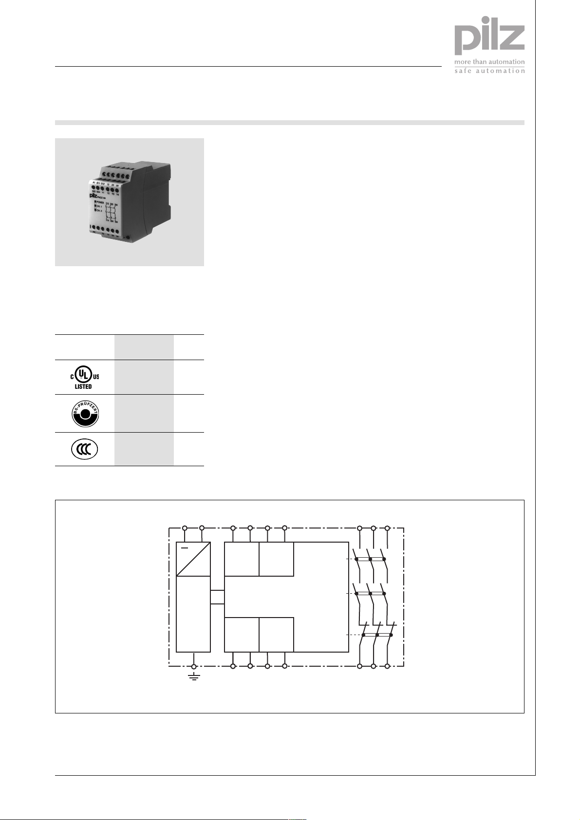
Block diagram
The relay conforms to the following
safety criteria:
A1 A2 S23 S24
~
S11 S12
InputInput
=
Power
Power
Reset/
Start
Y1 Y2
UB AC
Reset/
Start
Y3 Y4
13 23 33
K1
K2
K3
14 24 34
Pilz GmbH & Co. KG, Sichere Automation, Felix-Wankel-Straße 2, 73760 Ostfildern, Germany
Telephone: +49 711 3409-0, Telefax: +49 711 3409-133, E-Mail: pilz.gmbh@pilz.de
NSG-D-2-047-01/05
E-STOP relays, safety gate monitors
Up to Category 3, EN 954-1
PNOZ X6
Function description
` Single-channel operation: no red-
undancy in the input circuit, earth
faults in the reset and input circuit
are detected.
` Dual-channel operation without de-
tection of shorts across contacts:
redundant input circuit, detects
– earth faults in the reset and input
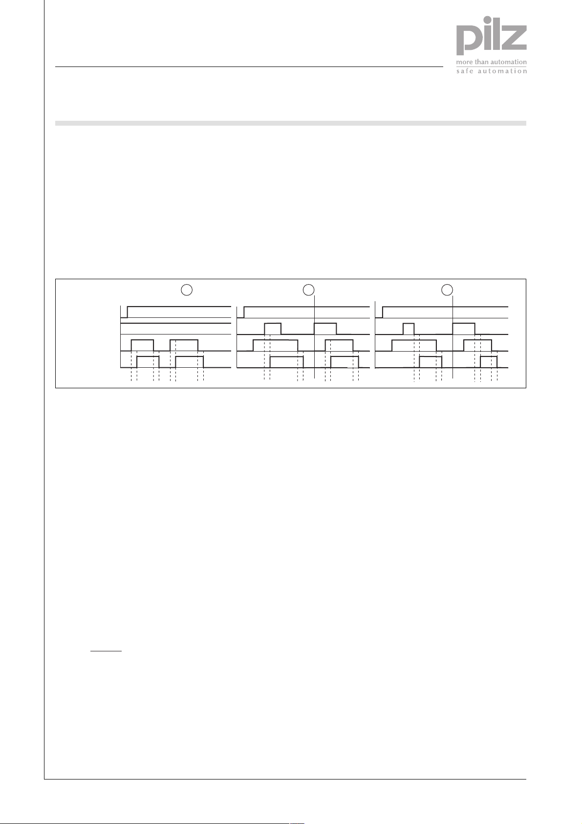
Timing diagram
1 2
POWER
Reset/Start
Input
Output safe
t1 t2
t1 t2
Key
` Power: Supply voltage
` Reset/start: Reset circuit Y1-Y2,
Y3-Y4
` Input: Input circuits S11-S12, S23-
S24
` Output safe: Safety contacts 13-14,
23-24, 33-34
circuit,
– short circuits in the input circuit
and, with a monitored reset, in
the reset circuit too.
` Automatic start: Unit is active once
the input circuit has been closed.
` Manual reset: Unit is active once
the input circuit is closed and then
the reset circuit is closed.
` M on it or ed re se t: Un i t i s ac ti ve on c e
ab
t1
t1
t2
t2
` c: Automatic reset
` d: Manual reset
` e: Monitored reset
` a: Input circuit closes before reset
circuit
` b: Reset circuit closes before input
circuit
– the input circuit is closed and
then the reset circuit is closed
and opened again.
– the reset circuit is closed and
then opened again once the input circuit is closed.
` Increase in the number of available
contacts by connecting contact expander modules or external contactors/relays.
ab
t1
: Switch-on delay
` t
1
: Delay-on de-energisation
` t
2
3
t2
t2
t1
Wiring
Please note:
` Information given in the “Technical
details” must be followed.
` Outputs 13-14, 23-24, 33-34 are
safety contacts.
` To prevent contact welding, a fuse
should be connected before the
output contacts (see technical details).
` Calculation of the max. cable runs
in the input circuit:
l
max
R
lmax
=
I
max
Rl / km
= max. overall cable resi-
R
lmax
stance (see technical details)
/km = cable resistance/km
R
l
` Use copper wire that can withstand
60/75 °C.
` Sufficient fuse protection must be
provided on all output contacts with
capacitive and inductive loads.
Telephone: +49 711 3409-0, Telefax: +49 711 3409-133, E-Mail: pilz.gmbh@pilz.de
NSG-D-2-047-01/05Pilz GmbH & Co. KG, Sichere Automation, Felix-Wankel-Straße 2, 73760 Ostfildern, Germany
-2
E-STOP relays, safety gate monitors
Up to Category 3, EN 954-1
PNOZ X6
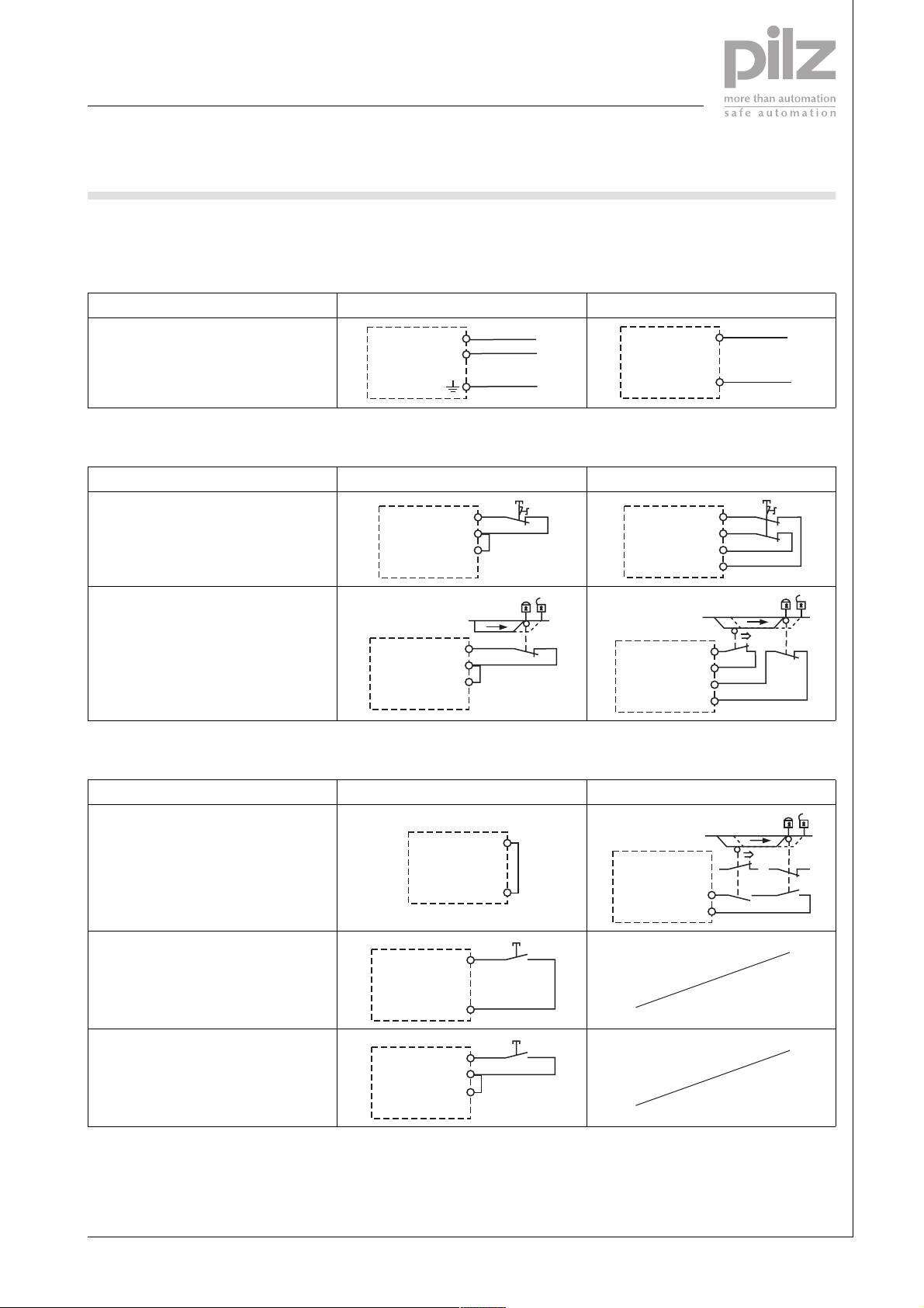
Preparing for operation
` Supply voltage
Supply voltage AC DC
A1
A2
L1
N
PE
` Input circuit
Input circuit Single-channel Dual-channel
E-STOP
without detection of shorts across
contacts
S11
S12
S24
S1
Safety gate
without detection of shorts across
contacts
S11
S12
S24
S1
` Reset circuit
S11
S12
S24
S23
A1
A2
S11
S23
S24
S12
S1
L+
L-
S1
S2
Reset circuit E-STOP wiring, safety gate Safety gate (dual-channel)
Automatic reset
Y1
Manual reset
Monitored reset
Y2
S3
Y1
Y2
S3
Y1
Y2
Y3
Y1
Y2
S2S1
Pilz GmbH & Co. KG, Sichere Automation, Felix-Wankel-Straße 2, 73760 Ostfildern, Germany
Telephone: +49 711 3409-0, Telefax: +49 711 3409-133, E-Mail: pilz.gmbh@pilz.de
NSG-D-2-047-01/05

E-STOP relays, safety gate monitors
Up to Category 3, EN 954-1
PNOZ X6
` Simultaneity monitoring
Simultaneity Simultaneity max. 200 ms Simultaneity ∞
Y3
Y4
` Feedback loop
Feedback loop Automatic reset Manual reset
Contacts from external contactors
Y1
Y2
13 (23, 33)
14 (24, 34)
K5
K6
K5
K6
L1
N
` Key
S1/S2 Two-hand button
S3 Reset button
Switch operated
Gate open
Gate closed
Y1
Y2
13 (23, 33)
14 (24 ,34)
K5
Y3
Y4
K6
K5
K6
S3
L1
N
Telephone: +49 711 3409-0, Telefax: +49 711 3409-133, E-Mail: pilz.gmbh@pilz.de
NSG-D-2-047-01/05Pilz GmbH & Co. KG, Sichere Automation, Felix-Wankel-Straße 2, 73760 Ostfildern, Germany
-4

E-STOP relays, safety gate monitors
Up to Category 3, EN 954-1
PNOZ X6
Terminal configuration
A1 S11 S12 13 23 33
S23A2S24 Y1Y2Y214Y324Y4
19586
PNOZ X6
POWER
CH. 1
CH. 2
2313 33
2414 34
34
Installation
` The safety relay should be installed
in a control cabinet with a protection type of at least IP54.
` Use the notch on the rear of the unit
to attach it to a DIN rail.
` Ensure the unit is mounted securely
on a vertical DIN rail (35 mm) by
using a fixing element (e.g. retaining
bracket or an end angle).
Dimensions
75 (2.95")
87 (3.42")
121 (4.76")
45
(1.77")
Pilz GmbH & Co. KG, Sichere Automation, Felix-Wankel-Straße 2, 73760 Ostfildern, Germany
Telephone: +49 711 3409-0, Telefax: +49 711 3409-133, E-Mail: pilz.gmbh@pilz.de
NSG-D-2-047-01/05

E-STOP relays, safety gate monitors
Up to Category 3, EN 954-1
PNOZ X6
Notice
Service life graph
This data sheet is only intended for use
during configuration. For installation
and operation, please refer to the ope-
10
AC1: 230 V
rating instructions supplied with the
unit.
DC13: 24 V
1
D Nennbetriebstrom (A)
GB Nominal operating current (A)
F Courant coupé (A)
Technical details
Electrical data
Supply voltage UB AC
Supply voltage U
B
DC
Voltage tolerance -15 % / 10 %
Power consumption at U
Power consumption at U
B
B
AC
DC
Frequency range AC 50 – 60 Hz
Residual ripple DC 160 %
Voltage and current at
input circuit: 24 VDC
reset circuit: 24 VDC
feedback loop: 24 VDC
Output contacts in accordance with EN 954-1, Category 3 Safety contacts (N/O): 3
Utilisation category in accordance with EN 60947-4-1
AC1: 240 V
AC1: 400 V
DC1: 24 V
Utilisation category in accordance with EN 60947-5-1
AC15: 230 V
DC13 (6 cycles/min): 24 V
Contact material AgSnO
External contact fuse protection (EN 60947-5-1)
Blow-out fuse, quick
Blow-out fuse, slow
Circuit breaker
Max. overall cable resistance R
reset circuits
input circuits,
lmax
Single-channel
Dual-channel without detection of shorts across contacts
0.1
E Corriente nominal de servicio (A)
I Corrente di esercizio nominale (A)
NL Nominale bedrijfsstroom (A)
10 100 1000 10000
D Schaltspielzahl x 10
GB Cycles x 10
F Nombre de manvres x 10
24 V, 42 V, 110 - 120 V, 230 - 240 V
24 V
6.5 VA Order no.: 774721, 774725, 774726
3.0 VA Order no.: 774729
2.0 W Order no.: 774729
50.0 mA
100.0 mA Order no.: 774721, 774725, 774726
55.0 mA Order no.: 774729
100.0 mA Order no.: 774721, 774725, 774726
55.0 mA Order no.: 774729
I
: 0.01 A, I
min
P
: 2000 VA
max
I
: 0.01 A, I
min
P
: 2000 VA
max
I
: 0.01 A, I
min
P
: 200 W
max
: 5.0 A
I
max
I
: 7.0 A
max
10 A
6 A
6 A, 24 VAC/DC, characteristic B/C
100 Ohm
200 Ohm
3
3
: 8.00 A
max
: 5.00 A
max
: 8.0 A
max
+ 0.2 µm Au
2
DC1: 24 V
AC1: 400 V
AC15: 230 V
E Número de ciclos x 10
I Numero dei cicli di commutazione x 10
3
NL Aantal schakelingen x 10
3
3
3
Telephone: +49 711 3409-0, Telefax: +49 711 3409-133, E-Mail: pilz.gmbh@pilz.de
NSG-D-2-047-01/05Pilz GmbH & Co. KG, Sichere Automation, Felix-Wankel-Straße 2, 73760 Ostfildern, Germany
-6

E-STOP relays, safety gate monitors
Up to Category 3, EN 954-1
PNOZ X6
Times
Switch-on delay
with automatic reset typ.
with automatic reset max.
with automatic reset after power on typ.
with automatic reset after power on max.
Delay-on de-energisation
with E-STOP typ.
with E-STOP max.
with power failure typ.
with power failure max.
Recovery time at max. switching frequency 1/s
after E-STOP
after power failure
Min. start pulse duration with a monitored reset 30 ms
Simultaneity, channel 1 and 2 200 ms / ∞
Supply interruption before de-energisation 20 ms
Environmental data
EMC EN 61000-6-2, EN 60947-5-1
Vibration in accordance with EN 60068-2-6
Frequency
Amplitude
Climatic suitability EN 600068-2-78
Airgap creepage EN 60947-1
Ambient temperature -10 – 55 °C
Storage temperature -40 – 85 °C
Protection type
Mounting (e.g. cabinet)
Housing
Terminals
Mechanical data
Housing material
Housing
Front
Max. cross section of external conductors with screw terminals
1 core flexible
2 core, same cross section, flexible:
with crimp connectors, without insulating sleeve
without crimp connectors or with TWIN crimp connectors
Torque setting with screw terminals 0.60 Nm
Dimensions (H x W x D)
with screw terminals 87.0 mm x 45.0 mm x 121.0 mm
Weight 390 g Order no.: 774721, 774725, 774726
270 ms Order no.: 774721, 774725, 774726
250 ms Order no.: 774729
370 ms Order no.: 774721, 774725, 774726
350 ms Order no.: 774729
260 ms
350 ms
15 ms
30 ms
150 ms Order no.: 774721, 774725, 774726
110 ms Order no.: 774729
200 ms Order no.: 774721, 774725, 774726
160 ms Order no.: 774729
50 ms
250 ms Order no.: 774721, 774725, 774726
200 ms Order no.: 774729
10 - 55 Hz
0.35 mm
IP54
IP40
IP20
PPO UL 94 V0
ABS UL 94 V0
0.20 - 4.00 mm
0.20 - 2.50 mm
0.20 - 2.50 mm
295 g Order no.: 774729
2
2
2
The standards current on 09/04 apply.
Max. continuous current
Number of contacts I
1 8.00 A Order no.: 774 729 8.00 A
2 8.00 A Order no.: 774 729 7.30 A
3 8.00 A Order no.: 774 729 6.00 A
Pilz GmbH & Co. KG, Sichere Automation, Felix-Wankel-Straße 2, 73760 Ostfildern, Germany
Telephone: +49 711 3409-0, Telefax: +49 711 3409-133, E-Mail: pilz.gmbh@pilz.de
(A) at UBDC I
max
(A) at UBAC
max
NSG-D-2-047-01/05

E-STOP relays, safety gate monitors
Up to Category 3, EN 954-1
PNOZ X6
Order reference
Type Features Terminals Order no.
PNOZ X6 42 VAC Screw terminals 774 721
PNOZ X6 110 - 120 VAC Screw terminals 774 725
PNOZ X6 230 - 240 VAC Screw terminals 774 726
PNOZ X6 24 VAC/DC Screw terminals 774 729
Telephone: +49 711 3409-0, Telefax: +49 711 3409-133, E-Mail: pilz.gmbh@pilz.de
NSG-D-2-047-01/05Pilz GmbH & Co. KG, Sichere Automation, Felix-Wankel-Straße 2, 73760 Ostfildern, Germany
-8
 Loading...