

E-STOP relays, safety gate monitors
Up to PL e of EN ISO 13849-1
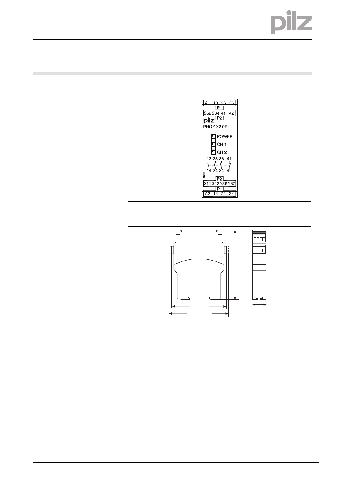
PNOZ X2.9P
Gertebild
][Bildunterschrift_NOT_Sch.tuer_Licht
Safety relay for monitoring E-STOP
pushbuttons, safety gates and light
beam devices
Approvals
PNOZ X2.9P
SÜDDEUTSCHLAND
Unit features
Gertemerkmale
` Positive-guided relay outputs:
– 3 safety contacts (N/O), instanta-
neous
– 1 auxiliary contact (N/C), instan-
taneous
` Connection options for:
– E-STOP pushbutton
– Safety gate limit switch
– Reset button
– Light barriers
` LED indicator for:
– Supply voltage
– Switch status channel 1/2
` Plug-in connection terminals (either
spring-loaded terminal or screw
terminal)
` See order reference for unit types
Unit description
Bestimmung/Gertebesc hreibung NOT-AUS , Schutzt, Lichtsc hr_PNOZ
The safety relay meets the requirements of EN 60947-5-1, EN 60204-1
and VDE 0113-1 and may be used in
applications with
` E-STOP pushbuttons
` Safety gates
` Light beam devices
Safety features
][Sicherheitseigenscha ften Schaltgerät_allgem einer Teil
The relay meets the following safety
requirements:
` The circuit is redundant with built-in
self-monitoring.
` The safety function remains effec-
tive in the case of a component failure.
` The correct opening and closing of
the safety function relays is tested
automatically in each on-off cycle.
Sicherheitseigenschaften
` No galvanic isolation between sup-
ply voltage and input circuit
Zulassungen
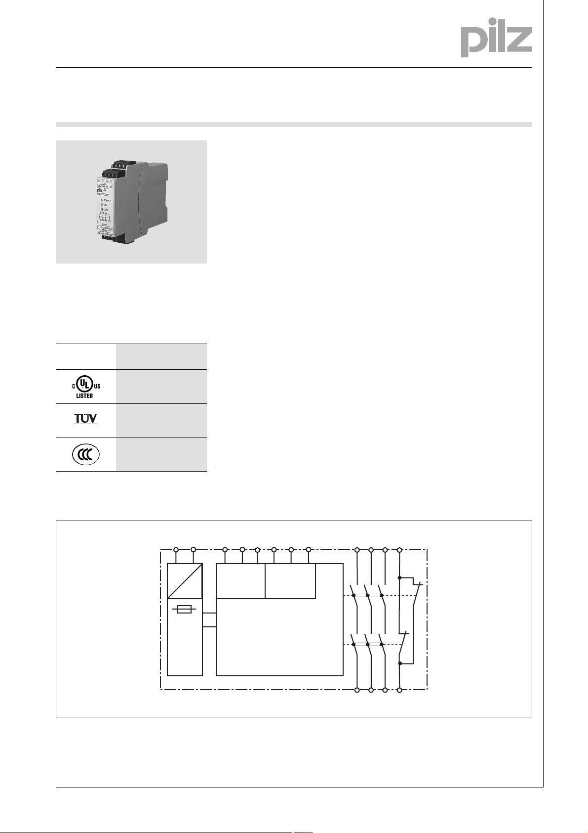
Block diagram
Blockschaltbild
A1 A2 Y36 Y37
S11 S12 S52
=
Input
S34
Reset/
Start
=
Power
13 23 33 41
K1
K2
14 24 34 42
1002002-EN-02-2011-01
E-STOP relays, safety gate monitors
Up to PL e of EN ISO 13849-1
PNOZ X2.9P
Function description
][Funktionen_einkanalig_Erd_Start
` Single-channel operation: no re-
dundancy in the input circuit, earth
faults in the reset circuit are detected.
][Funktionen_zweikanalig_ohne_quer
` Dual-channel operation without de-
tection of shorts across contacts:
redundant input circuit, detects
– earth faults in the reset and input
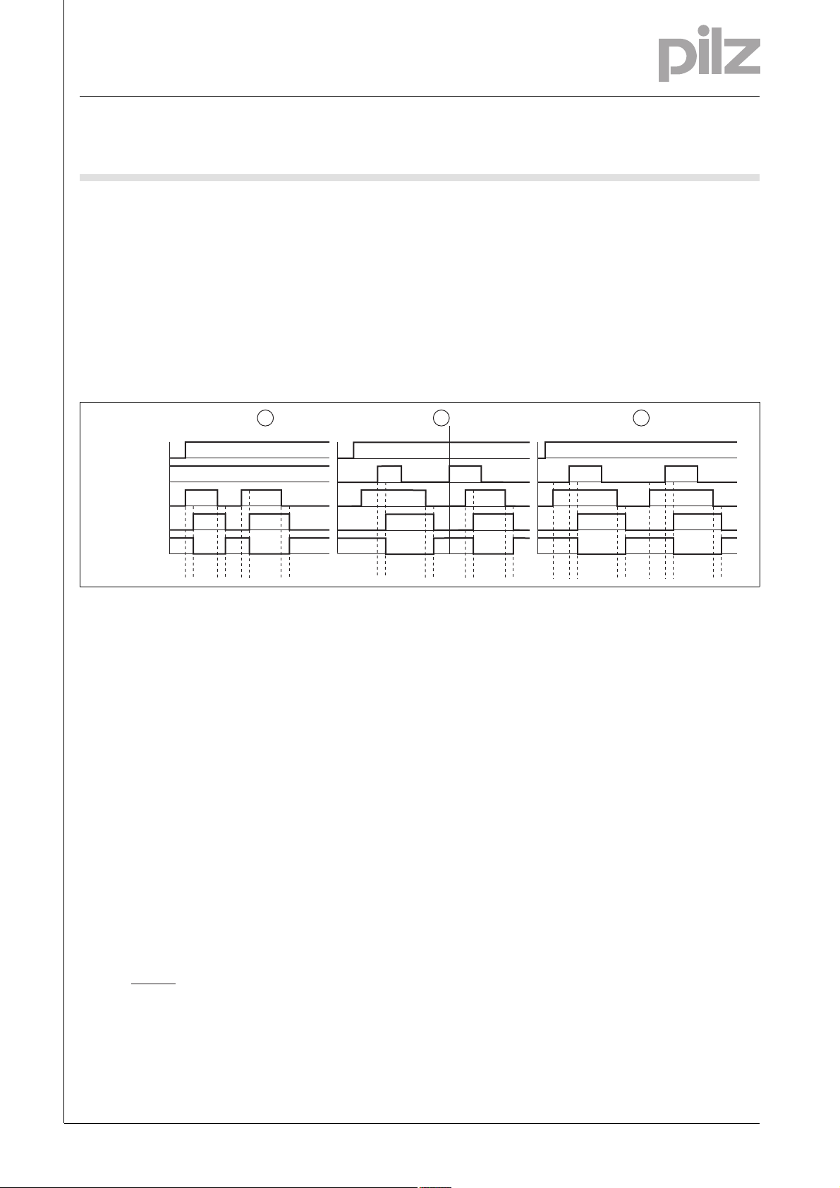
Timing diagram
1 2
POWER
Reset/Start
Input
Output safe
Output aux.
t1 t2
t1 t2
Key
` Power: Supply voltage
` Reset/start: Reset circuit S12-S34,
Y36-Y37
` Input: Input circuits S11, S12, S52
` Output safe: Safety outputs 13-14,
23-24, 33-34
circuit,
– short circuits in the input circuit
and, with a monitored reset, in
the reset circuit too.
][Funktionen_autoStart
` Automatic start: Unit is active once
the input circuit has been closed.
][Funktionen_manuStart
` Manual reset: Unit is active once
the input circuit is closed and then
the reset circuit is closed.
][Funktionen_berStart_Wartezeit
][Zeitdiagramm_auto_manu_ueber2_aux
ab
t1
t1
t2
` Output aux: Auxiliary contacts 41-
42
` c: Automatic reset
` d: Manual reset
` e: Monitored reset
` a: Input circuit closes before reset
circuit
` Monitored reset: Unit is active once
the input circuit is closed and once
the reset circuit is closed after the
waiting period has elapsed
(see technical details).
][Funktionen_Kontaktvervielfachung
` Increase in the number of available
instantaneous safety contacts by
connecting contact expansion
modules or external contactors.
3
t2
t1 t2 t1 t2t3 t3
` b: Reset circuit closes before input
circuit
: Switch-on delay
` t
1
` t2: Delay-on de-energisation
: Waiting period
` t
3
Wiring
][Verdrahtung_Si_unverz_1Hi_unverz
Please note:
` Information given in the “Technical
details” must be followed.
` Outputs 13-14, 23-24, 33-34 are
safety contacts, output 41-42 is an
auxiliary contact (e.g. for display).
` To prevent contact welding, a fuse
should be connected before the
output contacts (see technical details).
` Calculation of the max. cable runs
in the input circuit:
l
max
R
lmax
=
I
max
Rl / km
R
= max. overall cable resist-
lmax
ance (see technical details)
/km = cable resistance/km
R
l
` Use copper wire that can withstand
60/75 °C.
` Sufficient fuse protection must be
provided on all output contacts with
capacitive and inductive loads.
1002002-EN-02-2011-01
-2
E-STOP relays, safety gate monitors
Up to PL e of EN ISO 13849-1
PNOZ X2.9P
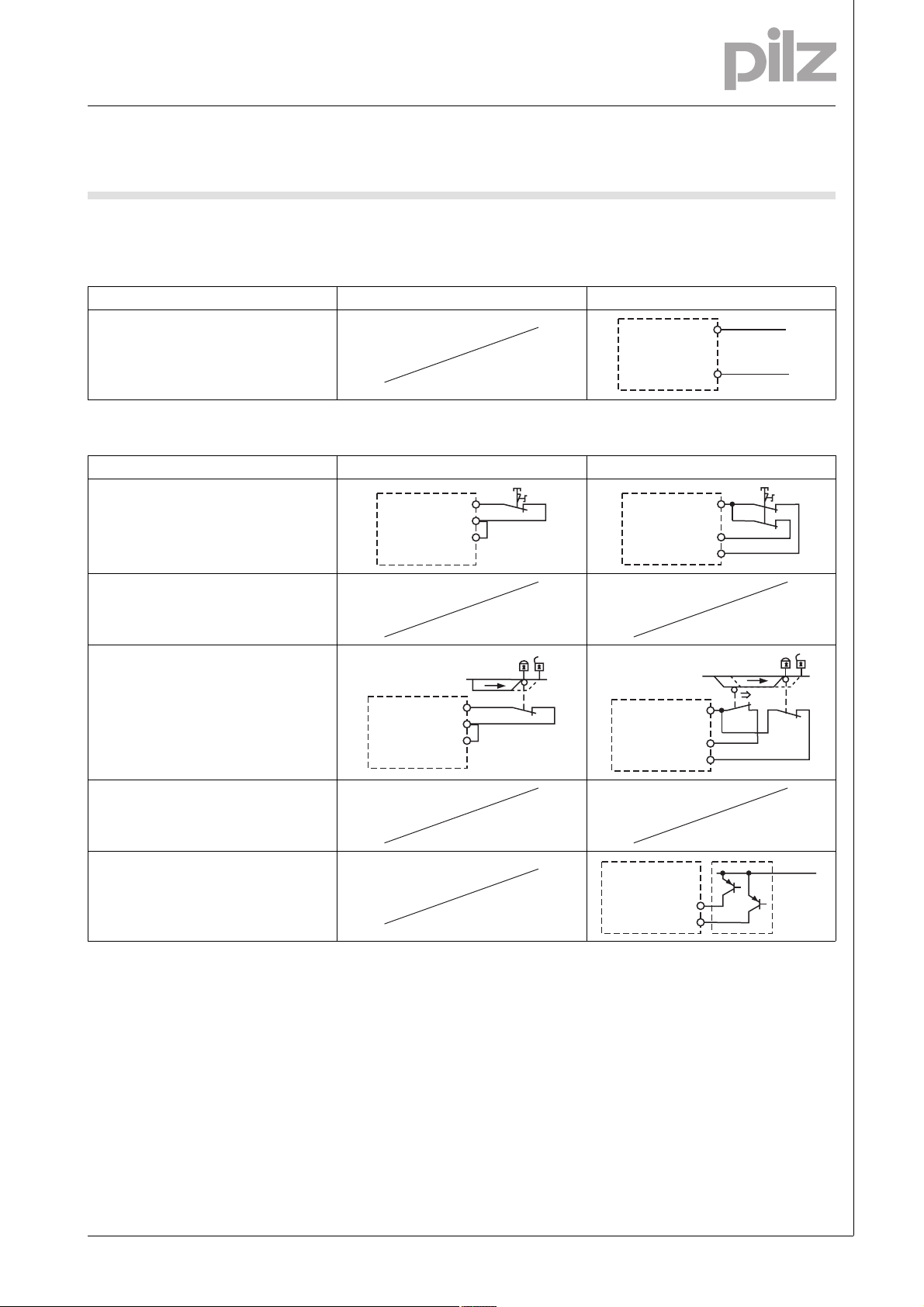
Preparing for operation
Betriebsbereitschaft her stellen
` Supply voltage
Supply voltage AC DC
` Input circuit
Input circuit Single-channel Dual-channel
E-STOP
without detection of shorts across contacts
E-STOP
with detection of shorts across contacts
Safety gate
without detection of shorts across contacts
S11
S12
S52
S11
S12
S52
S1
S1
S11
S12
S52
A1
A2
S11
S12
S52
S1
L+
L-
S1
S2
Safety gate
with detection of shorts across contacts
Light beam device
with detection of shorts across contacts
via ESPE
24 V DC
S12
S52
1002002-EN-02-2011-01
E-STOP relays, safety gate monitors
Up to PL e of EN ISO 13849-1
PNOZ X2.9P
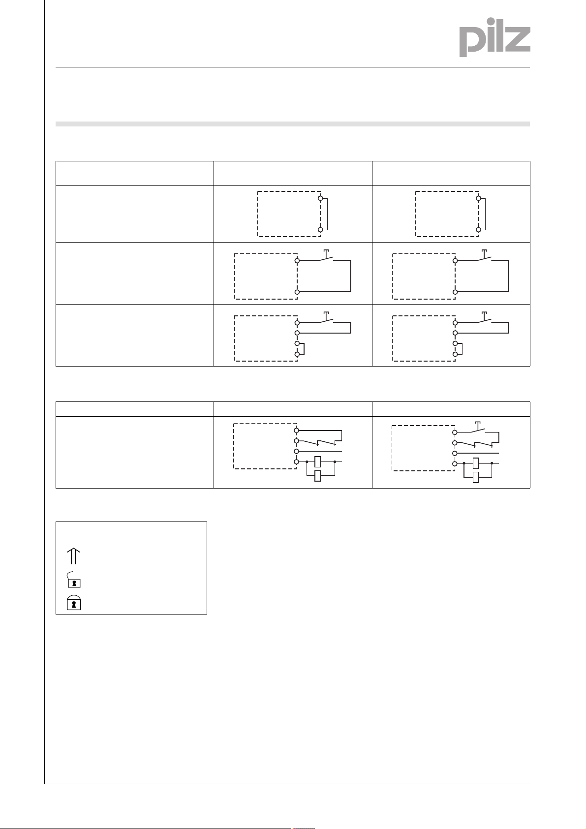
` Reset circuit
Reset circuit E-STOP wiring (single-channel)
Safety gate (single-channel)
Automatic reset
S12
S34
Manual reset
S12
S34
Monitored reset
S12
S34
Y36
Y37
S3
S3
E-STOP wiring (dual-channel)
Safety gate (dual-channel)
` Feedback circuit
Feedback circuit Automatic reset Manual reset
Contacts from external contactors
S12
S34
13 (23,33)
14 (24,34)
K5
K6
K5
K6
L1
N
S12
S34
S12
S34
Y36
Y37
S12
S34
13 (23, 33)
14 (24 ,34)
S12
S34
K5
K6
K5
K6
S3
S3
S3
L1
N
` Key
S1/S2 E-STOP/safety gate switch
S3 Reset button
Switch operated
Gate open
Gate closed
1002002-EN-02-2011-01
-4
E-STOP relays, safety gate monitors
Up to PL e of EN ISO 13849-1
PNOZ X2.9P
Terminal configuration
Klemmenbelegung
Installation
Montage_PNOZ_X
` The safety relay should be installed
in a control cabinet with a protection type of at least IP54.
` Use the notch on the rear of the unit
to attach it to a DIN rail.
` Ensure the unit is mounted securely
on a vertical DIN rail (35 mm) by using a fixing element (e.g. retaining
bracket or an end angle).
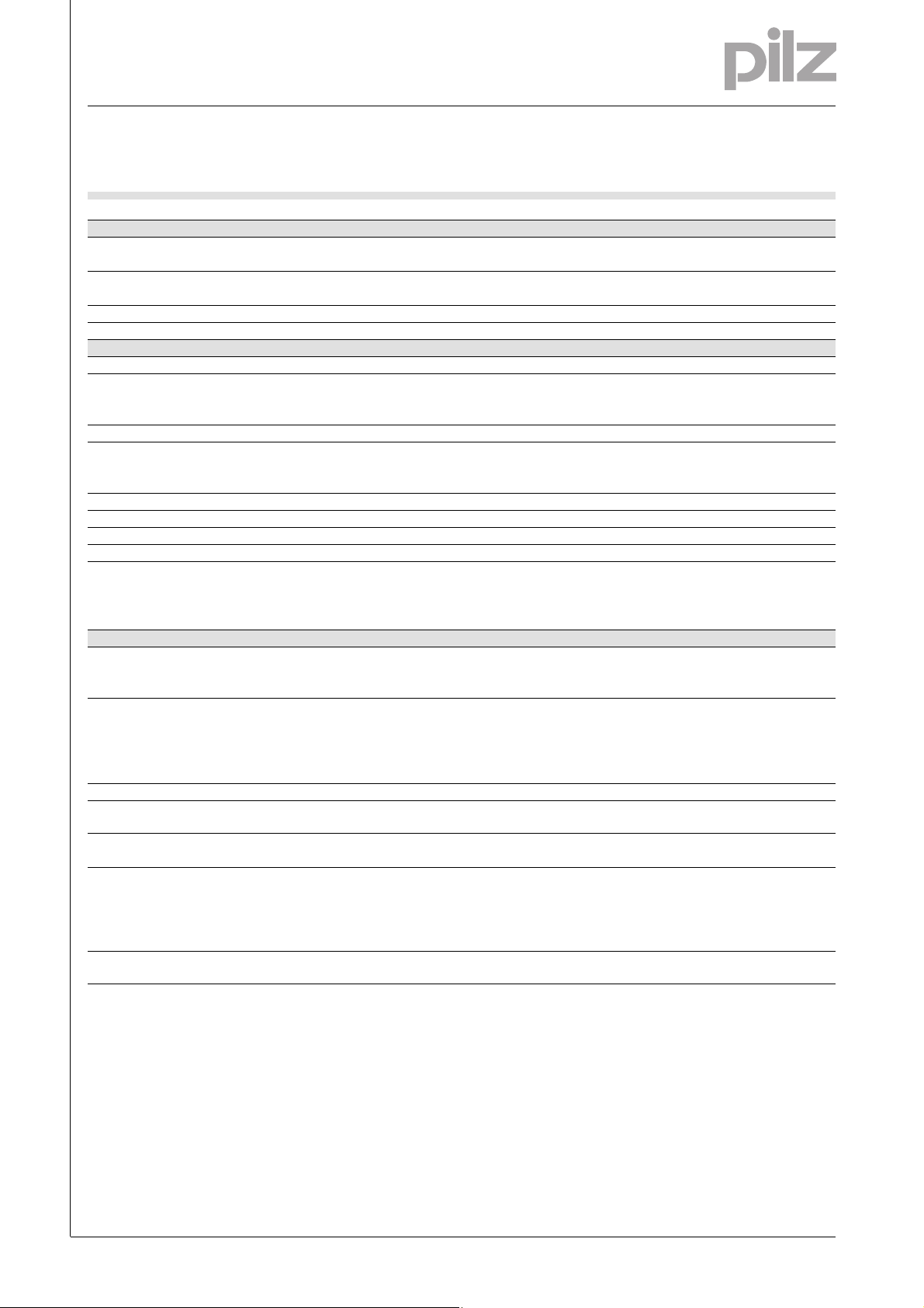
Dimensions in mm (")
Abmessungen
* with spring-loaded terminals
94 (3.70")
* 101 (3.98")
121 (4.76")
22,5
(0.88")
1002002-EN-02-2011-01

E-STOP relays, safety gate monitors
Up to PL e of EN ISO 13849-1
PNOZ X2.9P
Notice
][WICHTIG_PDB_alt
This data sheet is only intended for use
during configuration. For installation
and operation, please refer to the operating instructions supplied with the
unit.
Service life graph
Lebensdauerkurve_Rela is_Text vor Kurv e
The service life graphs indicate the
number of cycles from which failures
due to wear must be expected. The
wear is mainly caused by the electrical
load; the mechanical load is negligible.
Lebensdauerkurve_Relais_Text nach Kurve_SIS422 Bsp
Example
` Inductive load: 0.2 A
` Utilisation category: AC15
` Contact service life: 700 000 cycles
Provided the application requires fewer than 700 000 cycles, the PFH value
10
1
Courant coupé (A)
D Nennbetriebstrom (A)
GB Nominal operating current (A)
F
0.1
E Corriente nominal de servicio (A)
I Corrente di esercizio nominale (A)
NL Nominale bedrijfsstroom (A)
10 100 1000 10000
D Schaltspielzahl x 10
GB Cycles x 10
F Nombre de manuvres x 10
AC15: 230 V
DC13: 24 V
3
3
(see technical details) can be used in
the calculation.
To increase the service life, sufficient
spark suppression must be provided
on all output contacts. With capacitive
loads, any power surges that occur
Lebensdauerkurve
DC1: 24 V
AC1: 230 V
E Número de ciclos x 10
I Numero dei cicli di commutazione x 10
3
NL Aantal schakelingen x 10
3
3
must be noted. With contactors, use
freewheel diodes for spark suppression.
Lebensdauerkurve_Relais_Text nach Kurve-2_ Empfehlung sichere Halbleiterausgänge
We recommend you use semiconductor outputs to switch 24 VDC loads.
][Technische Daten PNO Z
3
Technical details
Electrical data
Supply voltage
Supply voltage U
DC 24 V
B
Voltage tolerance -15 %/+10 %
Power consumption at U
DC 2.0 W
B
Residual ripple DC 160 %
Voltage and current at
Input circuit DC: 24.0 V 30.0 mA
Reset circuit DC: 24.0 V 60.0 mA
Feedback loop DC: 24.0 V 60.0 mA
Number of output contacts
Safety contacts (S) instantaneous: 3
Auxiliary contacts (N/C): 1
1002002-EN-02-2011-01
-6

E-STOP relays, safety gate monitors
Up to PL e of EN ISO 13849-1
PNOZ X2.9P
Electrical data
Utilisation category in accordance with EN 60947-4-1
Safety contacts: AC1 at 240 V I
Safety contacts: DC1 at 24 V I
Auxiliary contacts: AC1 at 240 V I
Auxiliary contacts: DC1 at 24 V I
: 0.01 A , I
min
P
: 1500 VA
max
: 0.01 A , I
min
: 150 W
P
max
: 0.01 A , I
min
: 1500 VA
P
max
: 0.01 A , I
min
P
: 150 W
max
Utilisation category in accordance with EN 60947-5-1
Safety contacts: AC15 at 230 V I
Safety contacts: DC13 at 24 V (6 cycles/min) I
Auxiliary contacts: AC15 at 230 V I
Auxiliary contacts: DC13 at 24 V (6 cycles/min) I
max
max
max
max
: 3.0 A
: 4.0 A
: 3.0 A
: 4.0 A
Contact material AgSnO2 + 0.2 µm Au
External contact fuse protection (I
= 1 kA) to EN 60947-5-1
K
Blow-out fuse, quick
Safety contacts: 6 A
Auxiliary contacts: 6 A
Blow-out fuse, slow
Safety contacts: 4 A
Auxiliary contacts: 4 A
Circuit breaker 24 VAC/DC, characteristic B/C
Safety contacts: 4 A
Auxiliary contacts: 4 A
Max. overall cable resistance R
input circuits, reset circuits
single-channel at U
DC 50 Ohm
B
dual-channel without detect. of shorts across contacts at U
lmax
DC 80 Ohm
B
Min. input resistance when switching on 205 Ohm
Safety-related characteristic data
PL in accordance with EN ISO 13849-1: 2006 PL e (Cat. 4)
Category in accordance with EN 954-1 Cat. 4
SIL CL in accordance with EN IEC 62061 SIL CL 3
PFH in accordance with EN IEC 62061 2.31E-09
SIL in accordance with IEC 61511 SIL 3
PFD in accordance with IEC 61511 2.03E-06
t
in years 20
M
Times
Switch-on delay
with automatic reset typ. 200 ms
with automatic reset max. 400 ms
with automatic reset after power on typ. 200 ms
with automatic reset after power on max. 400 ms
with manual reset typ. 100 ms
with manual reset max. 400 ms
on monitored reset with rising edge typ. 30 ms
on monitored reset with rising edge max. 50 ms
Delay-on de-energisation
with E-STOP typ. 10 ms
with E-STOP max. 20 ms
with power failure typ. 70 ms
with power failure max. 120 ms
Recovery time at max. switching frequency 1/s
after E-STOP 50 ms
after power failure 150 ms
max
max
max
max
: 6.0 A
: 6.0 A
: 6.0 A
: 6.0 A
1002002-EN-02-2011-01
E-STOP relays, safety gate monitors
Up to PL e of EN ISO 13849-1
PNOZ X2.9P
Times
Waiting period with a monitored reset
with rising edge 200 ms
Min. start pulse duration with a monitored reset
with rising edge 30 ms
Simultaneity, channel 1 and 2 ∞
Supply interruption before de-energisation 20 ms
Environmental data
EMC EN 60947-5-1, EN 61000-6-2
Vibration to EN 60068-2-6
Frequency 10 - 55 Hz
Amplitude 0.35 mm
Climatic suitability EN 60068-2-78
Airgap creepage in accordance with EN 60947-1
Pollution degree 2
Overvoltage category III / II
Rated insulation voltage 250 V
Rated impulse withstand voltage 4.00 kV
Ambient temperature -10 - 55 °C
Storage temperature -40 - 85 °C
Protection type
Mounting (e.g. cabinet) IP54
Housing IP40
Terminals IP20
Mechanical data
Housing material
Housing PPO UL 94 V0
Front ABS UL 94 V0
Cross section of external conductors with screw terminals
1 core flexible 0.25 - 2.50 mm² , 24 - 12 AWG No. 777300
2 core, same cross section, flexible:
with crimp connectors, without insulating sleeve 0.25 - 1.00 mm² , 24 - 16 AWG No. 777300
without crimp connectors or with TWIN crimp connectors 0.20 - 1.50 mm² , 24 - 16 AWG No. 777300
Torque setting with screw terminals 0.50 Nm No. 777300
Cross section of external conductors with spring-loaded termi-
nals: Flexible with/without crimp connectors
Spring-loaded terminals: Terminal points per connection 2 No. 787300
Stripping length 8 mm No. 787300
Dimensions
Height 101.0 mm No. 787300
Width 22.5 mm
Depth 121.0 mm
Weight 175 g No. 787300
Technische Daten_Satz No .
No. stands for order number.
0.20 - 1.50 mm² , 24 - 16 AWG No. 787300
94.0 mm No. 777300
180 g No. 777300
Si-Kennzahlen_Zusatz_Relais_Lebensdauer_PDB
It is essential to consider the relay's
service life graphs. The relay outputs'
safety-related characteristic data is
only valid if the values in the service life
graphs are met.
All the units used within a safety function must be considered when calculating the safety characteristic data.
Technische Daten_Satz No rmen
The standards current on 2009-11 apply.
][Dauerstrom_DC
The PFH value depends on the switching frequency and the load on the relay
output.
If the service life graphs are not accessible, the stated PFH value can be
used irrespective of the switching frequency and the load, as the PFH value
already considers the relay's B10d value as well as the failure rates of the
other components.
Si_Kennzahlen_Erläute rung
1002002-EN-02-2011-01
-8

E-STOP relays, safety gate monitors
Up to PL e of EN ISO 13849-1
PNOZ X2.9P
Conventional thermal current
(A) at UBDC
I
th
1 contact 6.00 A
2 contacts 6.00 A
3 contacts 4.50 A
Order reference
Type Features Terminals Order no.
PNOZ X2.9P C 24 VDC Spring-loaded terminals 787 300
PNOZ X2.9P 24 VDC Screw terminals 777 300
Bestelldaten
1002002-EN-02-2011-01
 Loading...