


21 401-6NL-07
PNOZ s9
4 D Betriebsanleitung
4 GB Operating instructions
4 F Manuel d'utilisation
21 401-6NL-07PNOZ s9
Sicherheitsschaltgerät PNOZ s9
761002507
Das Gerät erfüllt die Forderungen der
EN 60947-5-1, EN 60204-1 und VDE 0113-1.
Das Gerät dient zusammen mit einem Grundgerät als
` Kontakterweiterungsblock zur Kontaktver-
stärkung und Kontaktvervielfältigung für ein
Grundgerät. Grundgeräte sind alle Sicherheitsschaltgeräte mit Rückführkreisüberwachung.
` Wischrelais (Impulsrelais)
– nach EN ISO 12100-1 und EN ISO 12100-
2 (Schrittschaltung für begrenzte Bewegung gefahrbringender Maschinenteile
während Montage-, Einricht- und Einstellarbeiten)
– in Sicherheitsstromkreisen nach VDE 0113
und EN 60204-1 (z. B. bei beweglichen
Verdeckungen)
` Sicheres Zeitrelais
– nach EN 1088 (Entsperrung mit Verzöge-
rung durch Zeiteinheit)
– in Sicherheitsstromkreisen nach
VDE 0113-1 und EN 60204-1 (z.B. bei be-
weglichen Verdeckungen)
Die zu realisierende Kategorie nach EN 954-1
und EN ISO 13849-1 ist abhängig von der Kategorie des Grundgeräts. Sie kann vom Kontakterweiterungsblock nicht überschritten
werden.
` Das Gerät kann auch ohne Grundgerät als
Wischrelais oder sicheres Zeitrelais eingesetzt werden.
Das Gerät ist bestimmt für den Einsatz mit
` Sicherheitsschaltgeräten der Reihe PNOZ X,
PNOZsigma, PNOZelog, PNOZmulti
` Schutztürwächtern der Reihe PST
` Zweihandbediengeräte der Reihe
PNOZsigma, P2HZ
Zu Ihrer Sicherheit
547263243
` Installieren und nehmen Sie das Gerät nur
dann in Betrieb, wenn Sie diese Betriebsanleitung gelesen und verstanden haben und
Sie mit den geltenden Vorschriften über Arbeitssicherheit und Unfallverhütung vertraut
sind.
Beachten Sie die VDE- sowie die örtlichen
Vorschriften, insbesondere hinsichtlich
Schutzmaßnahmen
` Durch Öffnen des Gehäuses oder eigen-
mächtige Umbauten erlischt jegliche Gewährleistung.
4 E Instrucciones de uso
4 I Istruzioni per l`uso
4 NL Gebruiksaanwijzing
Safety relay PNOZ s9
The unit meets the requirements of EN 609475-1, EN 60204-1 and VDE0113-1. In conjunction with a base unit the unit is used as a
` Contact expansion module to increase the
number of contacts available on a base unit.
Base units are all safety relays with feedback
loop monitoring.
` Pulse relay
– In accordance with EN ISO 12100-1 and
EN ISO 12100-2 (inching circuit for limited
movement of hazardous machine components during installation, set up and positioning)
– in safety circuits in accordance with
VDE 0113 and EN 60204-1 (e.g. on movable guards)
` Safe timer relays
– in accordance with EN 1088 (release with
delay through timer)
– in safety circuits in accordance with
VDE 0113-1 and EN 60204-1 (e.g. on mov-
able guards)
The category that can be achieved in accordance with EN 954-1 and EN ISO 13849-1 depends on the category of the base unit. The
contact expansion module may not exceed
this.
` The unit can also be used without a base unit
as a pulse relay or safe timer.
The unit is designed for use with
` Safety relays from the PNOZ X, PNOZsigma,
PNOZelog, PNOZmulti series
` Safety gate monitors from the PST series
` Two-hand relays from the PNOZsigma,
P2HZ series
For your safety
` Only install and commission the unit if you
have read and understood these operating
instructions and are familiar with the applicable regulations for health and safety at work
and accident prevention.
Ensure VDE and local regulations are met,
especially those relating to safety.
` Any guarantee is rendered invalid if the hous-
ing is opened or unauthorised modifications
are carried out.
Bloc logique de sécurité PNOZ s9
L'appareil satisfait aux exigences des normes
EN 60947-5-1, EN 60204-1 et VDE 0113-1 et
peut être utilisé avec un appareil de base en
tant que
` bloc d'extension de contacts pour une aug-
mentation et un renforcement du nombre de
contacts d'un appareil de base. Les appareils de base sont tous des blocs logiques de
sécurité avec surveillance de la boucle de retour.
` Relais de passage (relais d'impulsion)
– selon l'EN ISO 12100-1 et l'EN ISO 12100-
2 (marche à-coup pour un mouvement limité des éléments dangereux d'une machine pendant les travaux de montage, de
réglage et d'ajustage)
– dans les circuits de commande de sécurité
selon VDE 0113 et l'EN 60204-1 (par
exemple pour les protecteurs mobiles)
` Relais temporisé de sécurité
– selon l'EN 1088 (pilotage temporisé d'un
système d'interverrouillage)
– dans les circuits de commande de sécurité
selon VDE 0113-1 et l'EN 60204-1 (par
exemple pour des protecteurs mobiles)
La catégorie à atteindre conformément aux
normes EN 954-1 et EN ISO 13849-1 dépend
de la catégorie de l'appareil de base. Elle ne
peut pas être dépassée par le bloc d'extension
de contacts.
` L'appareil peut également être utilisé sans
appareil de base en tant que relais de passage ou relais temporisé de sécurité.
L'appareil est destiné à une utilisation avec
` blocs logiques de sécurité de la série
PNOZ X, PNOZsigma, PNOZelog et
PNOZmulti
` relais de surveillance de protecteur mobile
de la série PST
` relais de commande bimanuelle de la série
PNOZsigma, P2HZ
Pour votre sécurité
` Vous n'installerez l'appareil et ne le mettrez
en service qu'après avoir lu et compris le
présent manuel d'utilisation et vous être familiarisé avec les prescriptions en vigueur
sur la sécurité du travail et la prévention des
accidents.
Respectez les normes locales ou VDE, particulièrement en ce qui concerne la sécurité.
` L'ouverture de l'appareil ou sa modification
annule automatiquement la garantie.
- 1 -
Gerätemerkmale
761004427
` Relaisausgänge zwangsgeführt, wahlweise
unverzögert, rückfallverzögert (auch nach
triggerbar), wischend oder ansprechverzögert:
–3 Sicherheitskontakte
–1 Hilfskontakt
` Sichere Trennung der Sicherheitskontakte
17-18, 27-28, 37-38 von allen anderen
Stromkreisen
` Einschaltzeit, Wischzeit oder Rückfallverzö-
gerung einstellbar
` LED-Anzeige für:
– Versorgungsspannung
– Eingangszustand Kanal 1
– Eingangszustand Kanal 2
– Schaltzustand Kanal 1/2
–Startkreis
–Fehler
` steckbare Anschlussklemmen (wahlweise
Federkraftklemmen oder Schraubklemmen)
Sicherheitseigenschaften
1047602443
Das Gerät erfüllt folgende Sicherheitsanforderungen:
` Das Gerät überwacht seine Ausgangskon-
takte selbst.
` Die Sicherheitseinrichtung bleibt auch bei
Ausfall eines Bauteils wirksam.
` Erdschluss im Rückführkreis wird erkannt.
` Erdschluss im Eingangskreis:
Die Ausgangsrelais fallen ab und die Sicherheitskontakte öffnen.
114378891
` Das Gerät hat eine elektronische Sicherung.
Unit features
Positive-guided relay outputs, either instan-
`
-
taneous, delay-on de-energisation (also retriggerable), pulsing or delay-on
energisation:
– 3 safety contacts
– 1 auxiliary contact
` Safe separation of safety contacts 17-18, 27-
28, 37-38 from all other circuits
` Switch-on time, pulse time or delay-on de-
energisation selectable
` LED for:
– Supply voltage
– Input status, channel 1
– Input status, channel 2
– Switch status channel 1/2
– Reset circuit
–Errors
` Plug-in connection terminals (either spring-
loaded terminals or screw terminals)
Safety features
The unit meets the following safety requirements:
` The unit monitors its own output contacts.
` The safety function remains effective in the
case of a component failure.
` Earth fault in the feedback loop is detected.
` Earth fault in the input circuit:
The output relays de-energise and the safety contacts open.
` The unit has an electronic fuse.
Caractéristiques de l'appareil
Sorties de relais à contacts liés, au choix non
`
temporisés, temporisés à la retombée (également redéclenchable), de passage ou temporisés à l'appel :
– 3 contacts de sécurité
– 1 contact d'information
` Séparation galvanique entre les contacts de
sécurité 17-18, 27-28, 37-38 de tous les
autres circuits électriques
` Temps de montée, de passage ou tempori-
sation à la retombée réglables
` LEDs de visualisation pour les états
suivants :
– tension d'alimentation
– état d'entrée canal 1
– état d'entrée canal 2
– état de commutation des canaux 1/2
– circuit de réarmement
–erreurs
` Borniers débrochables (au choix avec rac-
cordement à ressort ou à vis)
Caractéristiques de sécurité
L'appareil satisfait aux exigences de sécurité
suivantes :
` L'appareil surveille lui-même ses contacts de
sortie.
` La sécurité reste garantie, même en cas de
défaillance d'un composant.
` La mise à la terre dans la boucle de retour est
détectée.
` Mise à la terre dans le circuit d'entrée :
les relais de sortie retombent et les contacts
de sécurité s'ouvrent.
` L'appareil est équipé d'une sécurité électro-
nique.
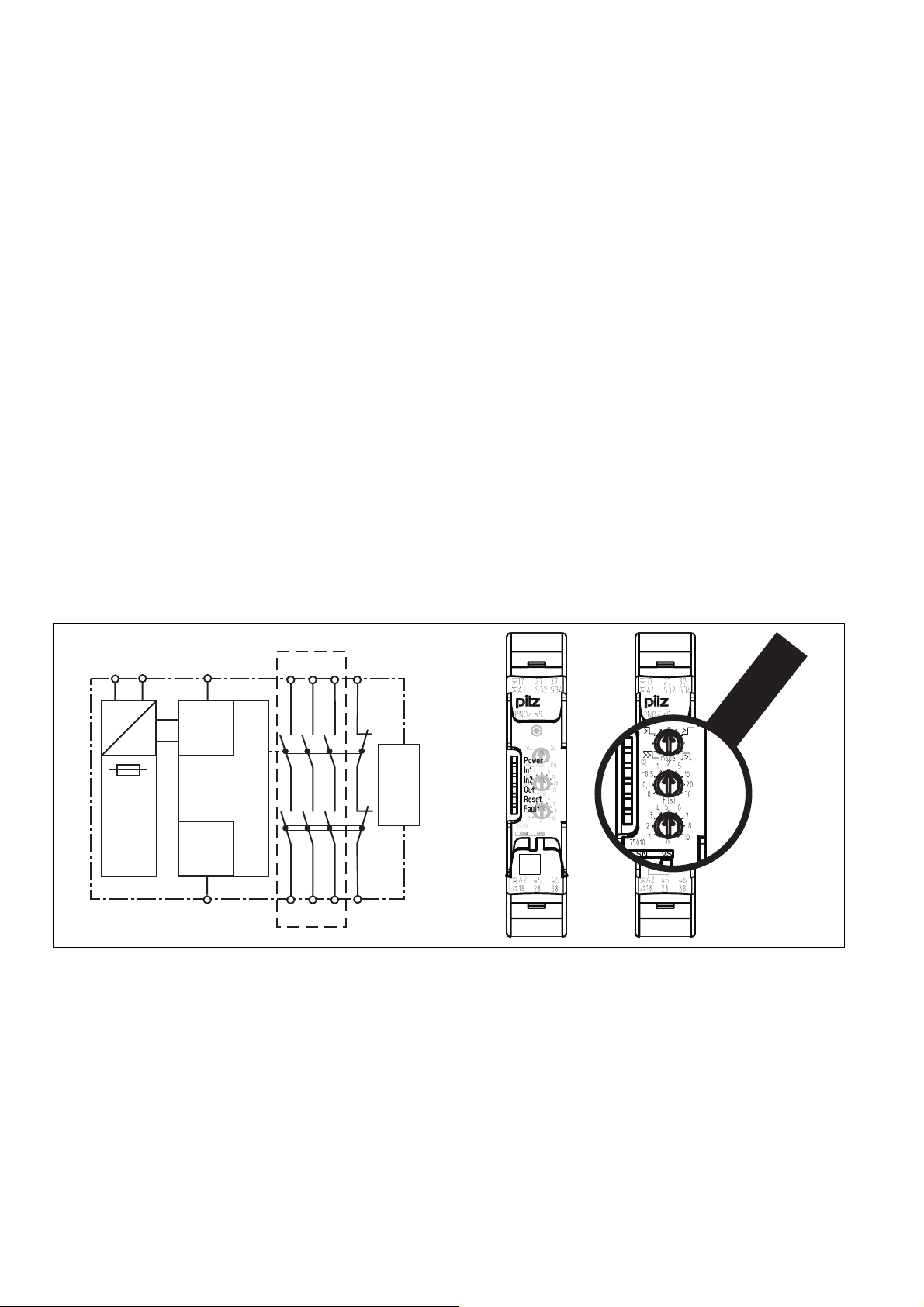
Blockschaltbild/Klemmenbelegung Block diagram/terminal configuration Schéma de principe / affectation des
bornes
A1 A2
S32
=
Input
=
Power
Reset
S34
569781643
*Sichere Trennung nach EN 60947-1, 6 kV
Mitte: Frontansicht mit Abdeckung
Rechts: Frontansicht ohne Abdeckung
K1
K2
*
45
37
17
27
unit
base
Interface
18
28 38 46
*Safe separation in accordance with
EN 60947-1, 6 kV
Centre: Front view with cover
Right: Front view without cover
* Séparation galvanique selon la norme
EN 60947-1, 6 kV
Schéma du milieu : vue frontale avec capot de
protection
A droite : vue frontale sans capot de protection
- 2 -

Funktionsbeschreibung
761123083
` rückfallverzögert, nicht nachtriggerbar
Ist die Versorgungsspannung am Eingangskreis unterbrochen, öffnen die Sicherheitskontakte nach Ablauf der
eingestellten Rückfallzeit, auch wenn die
Sicherheitsfunktion während der Verzögerungszeit zurückgenommen wird. Das
Gerät kann erst nach Ablauf der Verzögerungszeit wieder aktiviert werden.
` rückfallverzögert, nachtriggerbar
(nur als eigenständige Anwendung oder
mit PNOZsigma Grundgerät möglich!)
Ist die Versorgungsspannung am Eingangskreis unterbrochen, öffnen die Sicherheitskontakte nach Ablauf der
eingestellten Rückfallzeit.
Wird während der Verzögerungszeit die
Sicherheitsfunktion zurückgenommen
(z.B. Schutztür geschlossen), bleibt das
Gerät aktiv.
` einschaltwischend
Die Sicherheitskontakte schließen, wenn
die Versorgungsspannung anliegt, der
Rückführkreis geschlossen ist und danach der Eingangskreis geschlossen
wird. Nach Ablauf der Wischzeit werden
die Sicherheitskontakte wieder geöffnet.
Wird der Eingangskreis während der
Wischzeit für mehr als 10 ms geöffnet,
öffnen die Sicherheitskontakte sofort
und der Hilfskontakt wird geschlossen.
` ansprechverzögert
Die eingestellte Verzögerungszeit wird
gestartet, wenn die Versorgungsspannung anliegt, der Rückführkreis geschlossen ist und danach der
Eingangskreis geschlossen wird.
Wenn Eingangs- und Rückführkreis nach
Ablauf der Verzögerungszeit geschlossen sind, schließen die Sicherheitskontakte und der Hilfskontakt wird geöffnet.
Wird der Eingangskreis für mehr als 10
ms geöffnet, öffnen die Sicherheitskontakte sofort und der Hilfskontakt wird geschlossen.
1050357643
mit PNOZsigma Grundgerät:
` Zweikanalige Ansteuerung über PNOZsigma
Verbindungsstecker
mit anderen Grundgeräten oder ohne Grundgerät:
` Einkanalige Ansteuerung: ein Eingangskreis
wirkt auf die Ausgangsrelais
Function description
Delay-on de-energisation, not retriggera-
`
ble
If the supply voltage at the input circuit is
interrupted, the safety contacts will open
once the set release time has elapsed,
even if the safety function is cancelled
during the delay time. The unit cannot be
reactivated until the delay time has
elapsed.
` Delay-on de-energisation, retriggerable
(only possible as a standalone application or with the PNOZsigma base unit!)
If the supply voltage at the input circuit is
interrupted, the safety contacts will open
once the set release time has elapsed.
If the safety function is cancelled during
the delay time (e.g. safety gate closed),
the unit will remain active.
` Pulse on switching on
The safety contacts close when supply
voltage is applied, the feedback loop is
closed and finally the input circuit is
closed. The safety contacts are reopened once the pulse time has elapsed.
If the input circuit is opened for more
than 10 ms during the pulse time, the
safety contacts will open immediately
and the auxiliary contact will be closed.
` Delay-on energisation
The set delay time is started when supply
voltage is applied, the feedback loop is
closed and finally the input circuit is
closed.
If the input circuit and feedback loop are
closed once the delay time has elapsed,
the safety contacts will close and the
auxiliary contact will be opened.
If the input circuit is opened for more
than 10 ms, the safety contacts will open
immediately and the auxiliary contact will
be closed.
with PNOZsigma base unit:
` Dual-channel operation via PNOZsigma con-
nector
with other base units or without base unit:
` Single-channel operation: one input circuit
affects the output relays
Description du fonctionnement
temporisé à la retombée, non redéclen-
`
chable
Si la tension d'alimentation est interrompue sur le circuit d'entrée, les contacts
de sécurité s'ouvrent après l'expiration
du temps de retombée sélectionné, et
ce, même si la fonction de sécurité a été
annulée durant la temporisation. L'appareil ne peut être réactivé qu'après l'expiration de la temporisation.
` temporisé à la retombée, redéclenchable
(uniquement possible comme application autonome ou avec l'appareil de base
PNOZsigma !)
Si la tension d'alimentation est interrompue sur le circuit d'entrée, les contacts
de sécurité s'ouvrent après l'expiration
du temps de retombée configuré.
Si la fonction de sécurité est annulée durant la temporisation (par exemple, protecteur mobile fermé), l'appareil reste
actif.
` à contact de passage à l'appel
Les contacts de sécurité se ferment lorsque l'appareil est sous tension, la boucle
de retour puis le circuit d'entrée sont fermés. Après l'expiration du temps de passage, les contacts de sécurité s'ouvrent
de nouveau.
Si le circuit d'entrée est ouvert pendant
plus de 10 ms durant le temps de passage, les contacts de sécurité s'ouvrent immédiatement et le contact d'information
se ferme.
` temporisé à l'appel
La temporisation sélectionnée est lancée
lorsque l'appareil est sous tension, la
boucle de retour puis le circuit d'entrée
sont fermés.
Si le circuit d'entrée et la boucle de retour sont fermés après l'expiration de la
temporisation, les contacts de sécurité
se ferment et le contact d'information
s'ouvre.
Si le circuit d'entrée est ouvert pendant
plus de 10 ms, les contacts de sécurité
s'ouvrent immédiatement et le contact
d'information se ferme.
avec un appareil de base PNOZsigma
` Commande à deux canaux par le connecteur
PNOZsigma
avec d'autres appareils de base ou sans appareil de base :
` Commande monocanale : un circuit d'entrée
agit sur les relais de sortie
- 3 -

Montage
561318667
Kontakterweiterungsblock ohne Grundgerät montieren:
` Stellen Sie sicher, dass der Abschluss-
stecker seitlich am Gerät gesteckt ist
Grundgerät und Kontakterweiterungsblock
PNOZsigma verbinden:
` Entfernen Sie den Abschlussstecker seitlich
am Grundgerät und am Kontakterweiterungsblock
` Verbinden Sie das Grundgerät und den Kon-
takterweiterungsblock mit dem mitgelieferten Verbindungsstecker, bevor Sie die
Geräte auf der Normschiene montieren.
Montage im Schaltschrank
` Montieren Sie das Sicherheitsschaltgerät in
einen Schaltschrank mit einer Schutzart von
mindestens IP54.
` Befestigen Sie das Gerät mit Hilfe des Rast-
elements auf der Rückseite auf einer Normschiene (35 mm).
` Bei senkrechter Einbaulage: Sichern Sie das
Gerät durch ein Halteelement (z. B. Endhalter
oder Endwinkel).
` Vor dem Abheben von der Normschiene Ge-
rät nach oben oder unten schieben.
Installation
Install contact expander module without
base unit:
` Ensure that the plug terminator is inserted at
the side of the unit.
Connect base unit and PNOZsigma contact
expander module:
` Remove the plug terminator at the side of the
base unit and at the contact expander module
` Connect the base unit and the contact ex-
pander module to the supplied connector
before mounting the units to the DIN rail.
Installation in control cabinet
` The safety relay should be installed in a con-
trol cabinet with a protection type of at least
IP54.
` Use the notch on the rear of the unit to attach
it to a DIN rail (35 mm).
` When installed vertically: Secure the unit by
using a fixing element (e.g. retaining bracket
or end angle).
` Push the unit upwards or downwards before
lifting it from the DIN rail.
Montage
Installer le bloc d'extension de contacts
sans appareil de base :
` Assurez-vous que la fiche de terminaison est
branchée sur le côté de l'appareil.
Raccorder l'appareil de base et le bloc d'extension de contacts PNOZsigma
` Retirez la fiche de terminaison sur le côté de
l'appareil de base et sur le bloc d'extension
de contacts
` Avant de monter les appareils sur le rail DIN,
reliez l'appareil de base et le bloc d'extension de contacts à l'aide du connecteur fourni.
Montage dans une armoire
` Montez le bloc logique de sécurité dans une
armoire électrique ayant un indice de protection d'au moins IP54.
` Montez l'appareil sur un rail DIN à l'aide du
système de fixation situé sur la face arrière
(35 mm).
` Si l'appareil est monté à la verticale : sécuri-
sez-le à l'aide d'un élément de maintien
(exemple : support terminal ou équerre terminale).
` Avant de retirer l'appareil du rail DIN, pous-
sez l'appareil vers le haut ou vers le bas.
Verdrahtung
117588491
Beachten Sie:
` Angaben im Abschnitt „Technische Daten“
unbedingt einhalten.
` Die Ausgänge 17-18, 27-28, 37-38 sind Si-
cherheitskontakte, der Ausgang 45-46 ist ein
Hilfskontakt (z. B. für Anzeige).
` Vor die Ausgangskontakte eine Sicherung
(s. techn. Daten) schalten, um das Verschweißen der Kontakte zu verhindern.
` Berechnung der max. Leitungslänge I
Eingangskreis:
R
lmax
=
I
max
Rl / km
= max. Gesamtleitungswiderstand
R
lmax
(s. techn. Daten)
R
/ km = Leitungswiderstand/km
l
` Leitungsmaterial aus Kupferdraht mit einer
Temperaturbeständigkeit von 60/75 °C verwenden.
` Sorgen Sie an allen Ausgangskontakten bei
kapazitiven und induktiven Lasten für eine
ausreichende Schutzbeschaltung.
Wiring
Please note:
` Information given in the “Technical details”
must be followed.
` Outputs 17-18, 27-28, 37-38 are safety con-
tacts, output 45-46 is an auxiliary contact
(e.g. for display).
` To prevent contact welding, a fuse should be
connected before the output contacts (see
technical details).
im
` Calculation of the max. cable runs l
max
input circuit:
R
lmax
=
I
max
Rl / km
= max. overall cable resistance (see
R
lmax
technical details)
R
/km = cable resistance/km
l
` Use copper wire that can withstand
60/75 °C.
` Sufficient fuse protection must be provided
on all output contacts with capacitive and inductive loads.
max
Raccordement
Important :
` Respectez impérativement les données indi-
quées dans la partie "Caractéristiques techniques".
` Les sorties 17-18, 27-28, 37-38 sont des
contacts de sécurité, la sortie 45-46 est un
contact d'information (par exemple pour l'affichage).
` Protection des contacts de sortie par des fu-
in the
sibles (voir les caractéristiques techniques)
pour éviter leur soudage.
` Calcul de la longueur de câble max. I
le circuit d'entrée :
R
lmax
=
I
max
Rl / km
= résistance max. de l'ensemble du
R
lmax
câblage (voir les caractéristiques techniques)
/km = résistance du câblage/km
R
l
` Utilisez uniquement des fils de câblage en
cuivre résistant à des températures de
60/75 °C.
` Assurez-vous du pouvoir de coupure des
contacts de sortie en cas de charges capacitives ou inductives.
Betriebsbereitschaft herstellen Preparing for operation Préparation à la mise en service
Betriebsarten und Verzögerungszeit
599372811
Die Betriebsart und die Verzögerungszeit werden an den Drehschaltern am Gerät eingestellt.
Öffnen Sie dazu die Abdeckung auf der Frontseite des Geräts.
WICHTIG
Verstellen Sie die Drehschalter nicht während des Betriebs. Ansonsten erscheint
eine Fehlermeldung, die Sicherheitskontakte öffnen und das Gerät ist erst wieder
betriebsbereit, nachdem die Versorgungsspannung aus- und wieder eingeschaltet
wurde.
Operating modes and delay time
The operating mode and delay time are set via
the rotary switches on the unit. You can do this
by opening the cover on the front of the unit.
NOTICE
Do not adjust the rotary switch during operation, otherwise an error message will appear, the safety contacts will open and the
unit will not be ready for operation until the
supply voltage has been switched off and
then on again.
Modes de fonctionnement et temporisation
Le mode de fonctionnement et la temporisation
se règlent sur le sélecteur de l'appareil. Ouvrez
le capot de protection sur la face avant de l'appareil.
IMPORTANT
Ne modifiez pas le sélecteur en cours de
fonctionnement. Sinon, l'appareil signale
un défaut et les contacts de sécurité
s'ouvrent. L'appareil n'est alors prêt à refonctionner qu'après avoir coupé puis remis en marche la tension d'alimentation.
max
sur
- 4 -
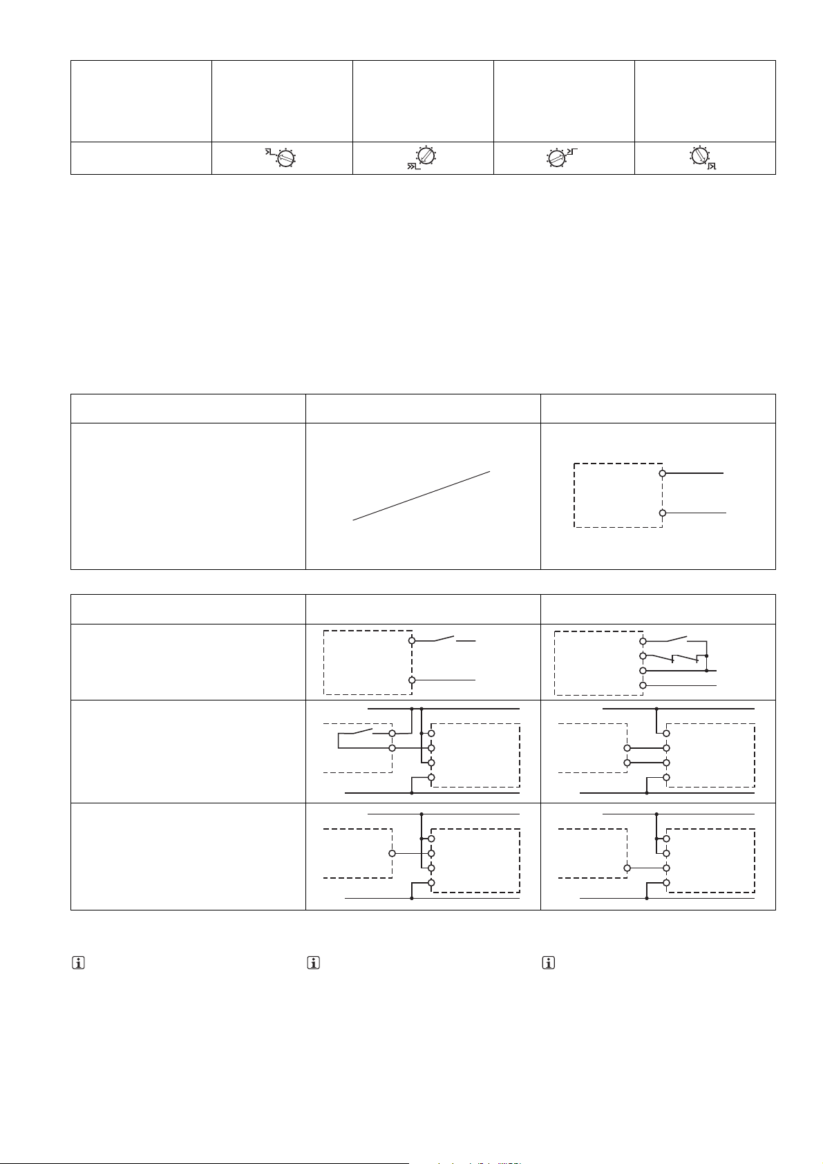
Betriebsarten einstellen Set operating modes Réglage des modes de fonctionnement
Betriebsartenwahlschalter
"mode"/
operating mode selector
switch "mode"/
sélecteur de mode de marche "mode"
568192395
` Versorgungsspannung ausschalten.
rückfallverzögert nicht
nachtriggerbar/ delay-on
de-energisation, not retriggerable/ temporisé à la retombée, non
redéclenchable
` Betriebsart mit dem Betriebsartenwahlschal-
ter "mode" wählen.
` Wenn der Betriebsartenwahlschalter "mode"
auf der Grundstellung ist (senkrechte Position), erscheint eine Fehlermeldung.
rückfallverzögert nachtriggerbar/ delay-on de-energisation, retriggerable/
ansprechverzögert/ delayon energisation/ temporisé
à l'appel
temporisé à la retombée,
redéclenchable
` Switch off supply voltage.
` Select operating mode via the operating
mode selector switch "mode".
` If the operating mode selector switch
"mode" is in its start position (vertical position), an error message will appear.
` Couper la tension d'alimentation.
` Sélectionner le mode de fonctionnement à
l'aide du sélecteur de mode de marche
«mode».
` Si le sélecteur de mode de marche « mode »
est positionné sur sa position de base (posi-
einschaltwischend/ pulse
on switching on/ à contact
de passage à l'appel
tion verticale), l'appareil signale une erreur.
Verzögerungszeit einstellen
599376267
Zeitenwahlschalter "t[s]"
Faktorwahlschalter "n"
n x t[s] = Verzögerungszeit
Beispiel:
t = 4 s, n = 5
Verzögerungszeit = 5 x 4 = 20 s
Set delay time
Time selector switch "t[s]"
Factor selector switch "n"
n x t[s] = Delay time
Example:
t = 4 s, n = 5
Delay time = 5 x 4 = 20 s
Régler la temporisation
Sélecteur de temporisation « t[s] »
Sélecteur de facteurs « n »
n x t[s] = temporisation
Exemple :
t = 4 s, n = 5
Temporisation = 5 x 4 = 20 s
Anschluss Connection Connexion
` Versorgungsspannung ` Supply voltage ` Tension d'alimentation
Versorgungsspannung/power supply/tension
d'alimentation
Achtung!
Die Versorgungsspannung darf nur wie in den
unten aufgeführten Beispielen angeschlossen
werden./
Caution!
The supply voltage must only be connected as
in the examples listed below./
Attention !
La tension d'alimentation doit uniquement être
raccordée comme indiqué dans les exemples
ci-dessous.
AC DC
A1
A2
L+
L-
` Eingangskreis 1-kanalig ` 1-channel input circuit ` Circuit d'entrée monocanal
ohne Grundgerät (stand alone)/
without base unit (standalone)/
sans appareil de base (autonome)
Grundgerät:
Sicherheitsschaltgerät PNOZ X/
Base unit:
PNOZ X safety relay
Appareil de base :
Bloc logique de sécurité PNOZ X
Grundgerät: Sicherheitsschaltgerät
PNOZelog; Ansteuerung durch Halbleiterausgänge (24 V DC)/
Base unit: PNOZelog safety relay; Driven via
semiconductor outputs (24 V DC)/
Appareil de base : Bloc logique de sécurité
PNOZelog; Commande par sorties statiques
(24 V DC)
841091595
* nur PNOZ e1p; alle anderen PNOZelog Sicherheitsschaltgeräte ohne Rückfallverzögerung bei PNOZ s9
INFO
zum Anschluss "Rückführkreis" mit Grundgeräten PNOZ X oder PNOZelog:
Die Eingänge, die den Rückführkreis auswerten sind abhängig vom Grundgerät und
von der Applikation.
Eingangskreis/Input circuit/
Circuit d'entrée
S3
A1
S32
S34
A2
A1
S32
S34
A2
+24 V DC
0 V
PNOZs9
PNOZs9
S32
A2
24 V DC
PNOZ X
0 V
24 V DC
PNOZelog
Output
0 V
* PNOZ e1p only; all other PNOZelog safety relays without delay-on de-energisation with
PNOZ s9
INFORMATION
To connect the "feedback loop" to PNOZ X
or PNOZelog base units:
The inputs that evaluate the feedback loop
depend on the base unit and application.
Rückführkreis/Feedback loop/
Boucle de retour
PNOZs9
24 V DC
PNOZ X
feedback
loop
0 V
24 V DC
PNOZelog
feedback
loop
0 V
S32
S34
A1
A2
K5
S34
45
46
A2
S34
45
46
A2
S3
K6
24 V DC
0 V
PNOZs9
PNOZs9
* uniquement PNOZ e1p ; tous les autres blocs
logiques de sécurité PNOZelog sans temporisation à la retombée pour PNOZ s9
INFORMATION
pour le raccordement de la « boucle de retour » avec des appareils de base PNOZ X
ou PNOZelog :
Les entrées qui analysent la boucle de retour dépendent de l'appareil de base et de
l'application.
*
- 5 -
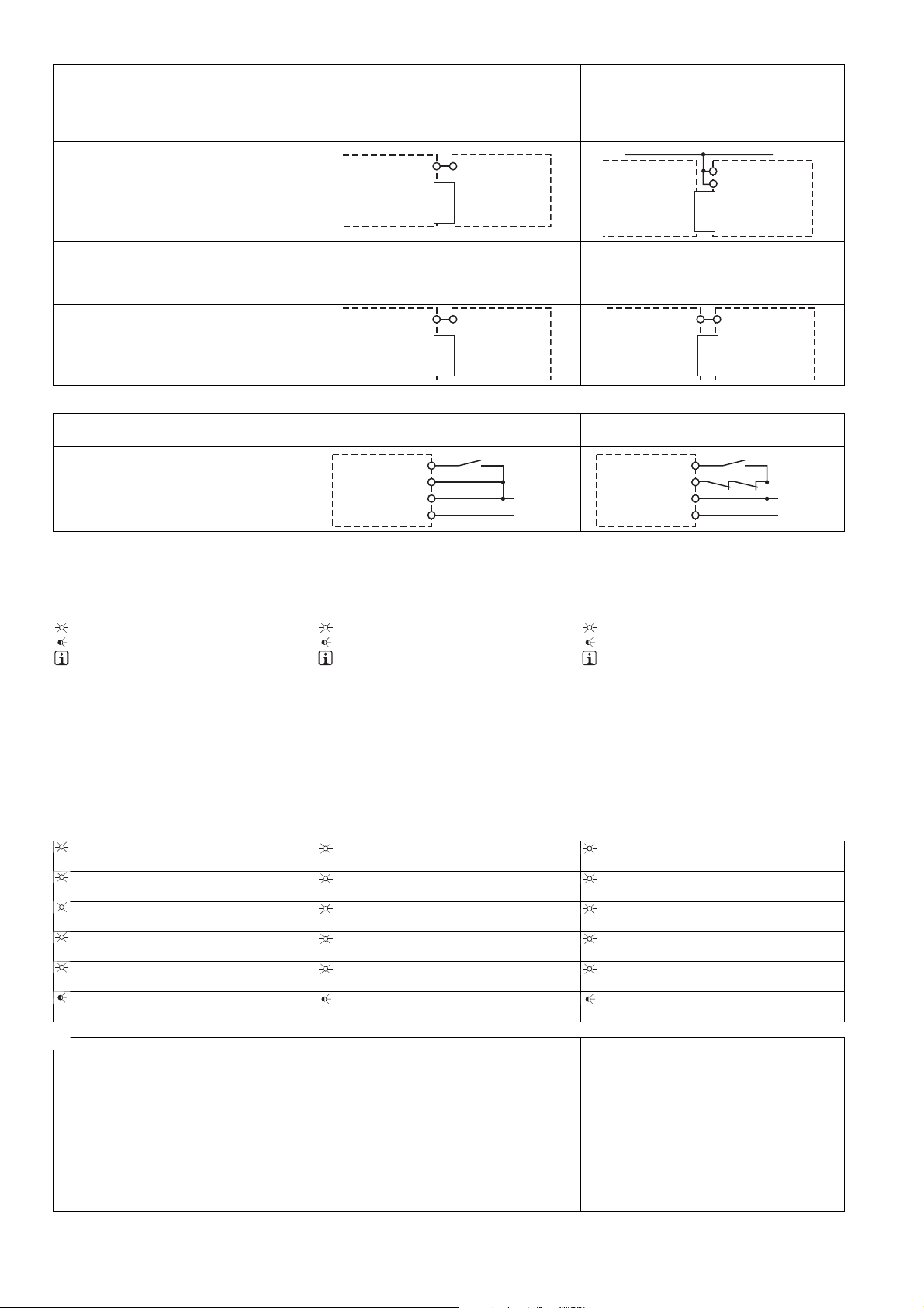
` Eingangskreis 2-kanalig ` 2-channel input circuit ` Circuit d'entrée à deux canaux
Der Eingangskreis wird über den Verbindungsstecker eingebunden und ausgewertet/ The input curcuit is connected and evaluated via the
connector/ Le circuit d'entrée est relié et analysé par le connecteur
Der Eingangskreis wird über den Verbindungsstecker eingebunden und ausgewertet/ The input curcuit is connected and evaluated via the
connector/ Le circuit d'entrée est relié et analysé par le connecteur
Grundgerät: Sicherheitsschaltgeräte
PNOZ s3, PNOZ s4, PNOZ s5/ Base units:
safety relays PNOZ s3, PNOZ s4, PNOZ s5/
Appareil de base : bloc logiques de sécurité
PNOZ s3, PNOZ s4, PNOZ s5
PNOZ s3
PNOZ s4
PNOZ s5
S11
Interface
PNOZsigma
S34
PNOZ s9
Grundgerät: Zweihandbediengerät PNOZ s6/
Base unit: Two-hand control device PNOZ s6/
Appareil de base : relais de commande bimanuelle PNOZ s6
S12
PNOZ s6
Interface
PNOZsigma
S34
PNOZ s9
Grundgerät: Sicherheitsschaltgeräte
PNOZ s1, PNOZ s2/ Base units: safety relays
PNOZ s1, PNOZ s2/ Appareil de base : bloc logiques de sécurité PNOZ s1, PNOZ s2
A1
S34
PNOZ s1
PNOZ s2
Interface
PNOZsigma
Grundgerät: Zweihandbediengerät
PNOZ s6.1/ Base unit: Two-hand control device PNOZ s6.1/ Appareil de base : relais de
commande bimanuelle PNOZ s6.1
S24
PNOZ s6.1
Interface
PNOZsigma
S34
` Applikation ` Application ` Application
ohne Grundgerät/ without base unit/ sans appareil de base
ohne Rückführkreis/ without feedback loop/
sans boucle de retour
PNOZs9
S32
S34
A1
A2
S3
24 V DC
0 V
mit Rückführkreis/ with feedback loop/ avec
boucle de retour
PNOZs9
S32
S34
A1
A2
K5
S3
K6
24 V DC
PNOZ s9
PNOZ s9
24 V DC
0 V
Betrieb
557883787
Das Gerät ist betriebsbereit, wenn die LED Power permanent leuchtet.
LEDs zeigen den Status und Fehler während
des Betriebs an:
LED leuchtet
LED blinkt
552061195
INFO
Statusanzeigen und Fehleranzeigen können unabhängig voneinander auftreten. Bei
einer Fehleranzeige leuchtet oder blinkt die
LED "Fault" (Ausnahme: "Versorgungsspannung zu gering"). Eine zusätzlich blinkende LED weist auf eine mögliche
Fehlerursache hin. Eine zusätzlich statisch
leuchtende LED weist auf einen normalen
Betriebszustand hin. Es können mehrere
Statusanzeigen und Fehleranzeigen gleichzeitig auftreten.
Statusanzeigen Status indicators Affichages de l'état
551604875
Power
Versorgungsspannung liegt an.
840819211
In1
Eingangskreis an S32 ist geschlossen.
840821387
In2
Eingangskreis an S32 ist geschlossen.
840823563
Out
Sicherheitskontakte sind geschlossen.
551614091
Reset
An S34 liegt 24 V DC an.
599616011
Out
Eingestellte Verzögerungszeit läuft.
Fehleranzeigen Fault indicators Affichage des erreurs
840828427
Alle LEDs aus
Gerät ausgeschaltet.
901369355
Fault
Diagnose: Abschlussstecker nicht gesteckt
` Abhilfe: Abschlussstecker stecken, Ver-
sorgungsspannung aus- und wieder ein-
schalten.
Mit Grundgerät PNOZsigma:
Diagnose: Eingangskreis S32 ist unerlaubt
geschlossen
Operation
The unit is ready for operation when the Power
LED is permanently lit.
LEDs indicate the status and errors during operation:
LED on
LED flashes
INFORMATION
Status indicators and error indicators may
occur independently. In the case of an error
display, the "Fault" LED will light or flash
(exception: "Supply voltage too low"). An
LED that is also flashing indicates the potential cause of the error. An LED that is lit
and is static indicates a normal operating
status. Several status indicators and error
indicators may occur simultaneously.
Power
Supply voltage is present.
In1
Input circuit at S32 is closed.
In2
Input circuit at S32 is closed.
Out
Safety contacts are closed.
Reset
24 VDC is present at S34.
Out
Set delay time is running.
All LEDs off
Unit switched off.
Fault
Diagnostics: Plug terminator not connected
` Remedy: Insert plug terminator, switch
supply voltage off and then on again.
With PNOZsigma base unit:
Diagnostics: Input circuit S32 is closed
without authorisation
Utilisation
L'appareil est prêt à fonctionner lorsque la LED
Power reste allumée en permanence.
Les LEDs indiquent l'état et les erreurs lors du
fonctionnement:
LED allumée
LED clignotante
INFORMATION
L'affichage de l'état et des erreurs peut survenir indépendamment. Lors de l'affichage
d'une erreur, la LED "Fault" s'allume ou clignote (exception : "Tension d'alimentation
trop faible"). Une LED clignotante supplémentaire informe sur une cause possible
d'erreur. Une LED supplémentaire qui s'allume de façon permanente informe de l'état
normal de fonctionnement. Plusieurs affichages de l'état et des erreurs peuvent survenir en même temps.
Power
la tension d'alimentation est présente.
In1
Le circuit d'entrée S32 est fermé.
In2
Le circuit d'entrée S32 est fermé.
Out
Les contacts de sécurité sont fermés.
Réarmement
24 V DC sur S34.
Out
La temporisation réglée fonctionne.
Toutes les LEDs sont éteintes
Appareil éteint.
Fault
Diagnostic : fiche de terminaison non branchée
` Solution : Brancher la fiche de terminai-
son, couper puis remettre en marche la
tension d'alimentation.
Avec appareil de base PNOZsigma :
Diagnostic : Le circuit d'entrée S32 est fermé sans autorisation.
- 6 -

551776267
Fault
Diagnose: Interner Fehler, Gerät defekt
` Abhilfe: Versorgungsspannung aus- und
wieder einschalten, gegebenenfalls Gerät tauschen.
551778571
Power
Diagnose: Versorgungsspannung zu gering
` Abhilfe: Versorgungsspannung überprü-
fen.
552056587
Reset
Fault
Diagnose: Unerlaubte Stellung eines Drehschalters oder ein Drehschalter wurde während des Betriebs verstellt.
` Abhilfe: Versorgungsspannung aus- und
wieder einschalten.
552058891
Power, In1, In2, Out, Reset, Fault
Diagnose: Der Betriebsartenwahlschalter
"mode" steht in Grundstellung (senkrechte
Position)
` Abhilfe: Versorgungsspannung aus-
schalten und am Betriebsartenwahlschalter "mode" gewünschte Betriebsart
einstellen.
Fehler - Störungen
551266315
` Fehlfunktionen der Kontakte: Bei ver-
schweißten Kontakten ist nach Öffnen des
Eingangskreises keine neue Aktivierung
möglich.
Fault
Diagnostics: Internal error, unit defective
` Remedy: Switch supply voltage off and
then on again, change unit if necessary.
Power
Diagnostics: Supply voltage too low
` Remedy: Check the supply voltage.
Reset
Fault
Di agn ost ics: Po sit ion of r ota ry switc h is not
permitted or rotary switch was adjusted
during operation.
` Remedy: Switch supply voltage off and
then on again.
Power, In1, In2, Out, Reset, Fault
Diagnostics: The operating mode selector
switch "mode" is in its start position (vertical position)
` Remedy: Switch off the supply voltage
and set the required operating mode on
operating mode selector switch "mode".
Faults - malfunctions
Contact malfunctions: If the contacts have
`
welded, reactivation will not be possible after
the input circuit has opened.
Fault
Diagnostic : erreur interne, appareil défectueux
` Remède : couper puis remettre en mar-
che la tension d'alimentation, si besoin
échanger l'appareil
Power
Diagnostic : tension d'alimentation trop faible
` Remède : vérifier la tension d'alimenta-
tion
Réarmement
Fault
Diagnostic : sélecteur rotatif dans une position incorrecte ou un sélecteur rotatif à été
déréglé durant le fonctionnement.
` Remède : couper puis remettre en mar-
che la tension d'alimentation.
Power, In1, In2, Out, Reset, Fault
Diagnostic : le sélecteur de mode de marche « mode » est positionné sur la position
de base (position verticale)
` Remède : coupez la tension d'alimenta-
tion et régler le mode de fonctionnement
souhaité sur le sélecteur de mode de
marche « mode ».
Erreurs – Défaillances
Défaut de fonctionnement des contacts de
`
sortie : si les contacts sont soudés, un réarmement est impossible après ouverture du
circuit d'entrée.
- 7 -

Technische Daten Technical details Caractéristiques techniques
Elektrische Daten Electrical data Données électriques
Versorgungsspannung Supply voltage Tension d'alimentation
Versorgungsspannung U
DC Supply voltage UB DC Tension d'alimentation UBDC 24 V
B
Spannungstoleranz Voltage tolerance Plage de la tension d'alimentation -20 %/+20 %
Leistungsaufnahme bei U
DC Power consumption at UB DC Consommation UBDC 2,0 W
B
Restwelligkeit DC Residual ripple DC Ondulation résiduelle DC 20 %
Versorgungsstrom an A1 typ. Typ. supply current at A1 Courant d'alimentation sur A1 env. 70 mA
Spannung und Strom an Voltage and current at Tension et courant sur
Eingangskreis DC: Input circuit DC: circuit d'entrée DC : 15,0 mA
Rückführkreis DC: 24,0 V Feedback loop DC: 24,0 V boucle de retour DC : 24,0 V 15,0 mA
Max. Einschaltstromimpuls Max. inrush current impulse Impulsion de courant max. lors de
la mise sous tension
A1 A1 A1 0,70 A
Eingangskreis Input circuit Circuit d'entrée 0,10 A
Rückführkreis Feedback loop Boucle de retour 0,10 A
Anzahl der Ausgangskontakte Number of output contacts Nombre de contacts de sortie
Sicherheitskontakte (S) verzögert: Safety contacts (N/O), delayed: Contacts de sécurité (F) temporisés :3
Hilfskontakte (Ö) verzögert: Auxiliary contacts (N/C), delayed: Contacts d'information (O) tempori-
1
sés :
Gebrauchskategorie nach
EN 60947-4-1
Sicherheitskontakte: AC1 bei 240 V Safety contacts: AC1 at 240 V Contacts de sécurité : AC1
Sicherheitskontakte: DC1 bei 24 V Safety contacts: DC1 at 24 V Contacts de sécurité : DC1 pour
Hilfskontakte: AC1 bei 240 V Auxiliary contacts: AC1 at 240 V Contacts d'information : AC1
Hilfskontakte: DC1 bei 24 V Auxiliary contacts: DC1 at 24 V Contacts d'information : DC1
Gebrauchskategorie nach
EN 60947-5-1
Sicherheitskontakte: AC15 bei
230 V
Sicherheitskontakte: DC13 bei 24 V
(6 Schaltspiele/min)
Hilfskontakte: AC15 bei 230 V Auxiliary contacts: AC15 at 230 V Contacts d'information : AC15
Hilfskontakte: DC13 bei 24 V (6
Schaltspiele/min)
Utilisation category in accordance
with EN 60947-4-1
Catégorie d'utilisation selon
EN 60947-4-1
pour 240 V
24 V
pour 240 V
pour 24 V
Utilisation category in accordance
with EN 60947-5-1
Catégorie d'utilisation selon
EN 60947-5-1
Safety contacts: AC15 at 230 V Contacts de sécurité : AC15
pour 230 V
Safety contacts: DC13 at 24 V
(6 cycles/min)
Contacts de sécurité : DC13
pour 24 V (6 manœuvres/min)
pour 230 V
Auxiliary contacts: DC13 at 24 V
(6 cycles/min)
Contacts d'information : DC13
pour 24 V (6 manœuvres/min)
I
: 0,01 A , I
min
P
: 1500 VA
max
I
: 0,01 A , I
min
P
: 150 W
max
: 0,01 A , I
I
min
P
: 1500 VA
max
: 0,01 A , I
I
min
P
: 150 W
max
I
: 5,0 A
max
I
: 5,0 A
max
I
: 5,0 A
max
I
: 5,0 A
max
max
max
max
max
: 6,0 A
: 6,0 A
: 6,0 A
: 6,0 A
Konventioneller thermischer Strom Conventional thermal current Courant thermique conventionnel 6,0 A
Kontaktmaterial Contact material Matériau des contacts AgCuNi + 0,2 µm Au
Kontaktabsicherung, extern
= 1 kA) nach EN 60947-5-1
(I
K
External contact fuse protection
(IK = 1 kA) to EN 60947-5-1
Protection des contacts en externe
(IK = 1 kA) selon EN 60947-5-1
Schmelzsicherung flink Blow-out fuse, quick Fusible rapide
Sicherheitskontakte: Safety contacts: Contacts de sécurité : 10 A
Hilfskontakte: Auxiliary contacts: Contacts d'information : 10 A
Schmelzsicherung träge Blow-out fuse, slow Fusible normal
Sicherheitskontakte: Safety contacts: Contacts de sécurité : 6 A
Hilfskontakte: Auxiliary contacts: Contacts d'information : 6 A
Sicherungsautomat 24V AC/DC,
Charakteristik B/C
Circuit breaker 24 VAC/DC, characteristic B/C
Disjoncteur 24 V AC/DC, caractéristique B/C
Sicherheitskontakte: Safety contacts: Contacts de sécurité : 6 A
Hilfskontakte: Auxiliary contacts: Contacts d'information : 6 A
Max. Gesamtleitungswiderstand
R
lmax
Max. overall cable resistance
R
lmax
Résistance max. de l'ensemble du
câblage R
lmax
A1/A2 A1/A2 A1/A2 20 Ohm
Eingangskreis Input circuit Circuit d'entrée 30 Ohm
Rückführkreis Feedback loop Boucle de retour 30 Ohm
- 8 -

Sicherheitstechnische Kenndaten
PL nach EN ISO 13849-1 PL in accordance with
Kategorie nach EN 954-1 Category in accordance with
SIL CL nach EN IEC 62061 SIL CL in accordance with
PFH nach EN IEC 62061 PFH in accordance with
Safety-related characteristic
data
EN ISO 13849-1
EN 954-1
EN IEC 62061
EN IEC 62061
Caractéristiques techniques de
sécurité
PL selon EN ISO 13849-1
PL e (Cat. 4)
Catégorie selon EN 954-1
Cat. 4
SIL CL selon EN IEC 62061
SIL CL 3
PFH selon EN IEC 62061
2,34E-09
SIL nach IEC 61511 SIL in accordance with IEC 61511 SIL selon IEC 61511 SIL 3
PFD nach IEC 61511 PFD in accordance with IEC 61511 PFD selon IEC 61511 2,75E-05
in Jahren tM in years tM en années 20
t
M
Zeiten Times Temporisations
Einschaltverzögerung Switch-on delay Temps de montée
bei manuellem Start typ. with manual reset typ. pour un réarmement manuel env. 60 ms
bei manuellem Start max. with manual reset max. pour un réarmement manuel max. 80 ms
Rückfallverzögerung Delay-on de-energisation Temps de retombée
bei Not-Halt typ. with E-STOP typ. sur un arrêt d'urgence env. 40 ms
bei Not-Halt max. with E-STOP max. sur un arrêt d'urgence max. 50 ms
Wiederbereitschaftszeit bei max.
Schaltfrequenz 1/s
Recovery time at max. switching
frequency 1/s
Temps de remise en service pour
une fréquence de commutation
max. de 1/s
nach Netzausfall after power failure après une coupure d'alimentation 800 ms
Verzögerungszeit t
: einstellbar Delay time tV: selectable Temporisation tV : réglable 0,00 s; 0,10 s; 0,20 s; 0,30 s;
V
0,40 s; 0,50 s; 0,60 s; 0,70 s;
0,80 s; 1,00 s; 1,50 s; 2,00 s;
2,50 s; 3,00 s; 3,50 s; 4,00 s;
5,00 s; 6,00 s; 7,00 s; 8,00 s;
10,00 s; 12,00 s; 14,00 s; 15,00
s; 16,00 s; 20,00 s; 25,00 s;
30,00 s; 35,00 s; 40,00 s; 50,00
s; 60,00 s; 70,00 s; 80,00 s;
90,00 s; 100,00 s; 120,00 s;
140,00 s; 150,00 s; 160,00 s;
180,00 s; 200,00 s; 210,00 s;
240,00 s; 300,00 s
Wiederholgenauigkeit Repetition accuracy Précision en reproductibilité +/- 1% + +/-20ms
Wiederholgenauigkeit im Fehlerfall Repetition accuracy in the case of a
fault
Précision en reproductibilité en cas
de défaut
+/- 15% + +/-20ms
Zeitgenauigkeit Time accuracy Précision temporelle +/- 1% + +/-20ms
Überbrückung bei Spannungsein-
brüchen der Versorgungsspannung
Überbrückung bei Spannungsein-
brüchen im Eingangskreis
Supply interruption before de-energisation
Supply interruption before de-energisation in the input circuit
Inhibition en cas de micro-coupures
de la tension d'alimentation
Inhibition en cas de micro-coupures
dans le circuit d'entrée
10 ms
10,0 ms
Umweltdaten Environmental data Données sur l'environnement
EMV EMC CEM EN 60947-5-1, EN 61000-6-2,
EN 61000-6-4
Schwingungen nach EN 60068-2-6 Vibration to EN 60068-2-6 Vibrations selon EN 60068-2-6
Frequenz Frequency Fréquence 10 - 55 Hz
Amplitude Amplitude Amplitude 0,35 mm
Klimabeanspruchung Climatic suitability Sollicitations climatiques EN 60068-2-78
Luft- und Kriechstrecken nach
EN 60947-1
Airgap creepage in accordance
with EN 60947-1
Cheminement et claquage
selon EN 60947-1
Verschmutzungsgrad Pollution degree Niveau d'encrassement 2
Überspannungskategorie Overvoltage category Catégorie de surtensions III
Bemessungsisolationsspannung Rated insulation voltage Tension assignée d'isolement 250 V
Bemessungsstoßspannungsfestig-
keit
Rated impulse withstand voltage Tension assignée de tenue aux
chocs
6,00 kV
Umgebungstemperatur Ambient temperature Température d'utilisation -15 - 55 °C
Lagertemperatur Storage temperature Température de stockage -40 - 85 °C
Schutzart Protection type Indice de protection
Einbauraum (z. B. Schaltschrank) Mounting (e.g. cabinet) Lieu d'implantation (par exemple :
IP54
armoire électrique)
Gehäuse Housing Boîtier IP40
Klemmenbereich Terminals Borniers IP 20
Mechanische Daten Mechanical data Données mécaniques
Gehäusematerial Housing material Matériau du boîtier
Gehäuse Housing Boîtier PC
Front Front Face avant PC
- 9 -

Mechanische Daten Mechanical data Données mécaniques
Querschnitt des Außenleiters bei
Schraubklemmen
Cross section of external conductors with screw terminals
Capacité de raccordement des borniers à vis
1 Leiter flexibel 1 core flexible 1 câble flexible 0,25 - 2,50 mm² , 24 - 12 AWG
No. 750109
2 Leiter gleichen Querschnitts, flexibel:
mit Aderendhülse, ohne Kunststoffhülse
ohne Aderendhülse oder mit TWIN
Aderendhülse
Anzugsdrehmoment bei Schraubklemmen
Querschnitt des Außenleiters bei
Federkraftklemmen: flexibel mit/
ohne Aderendhülse
2 core, same cross section, flexible: 2 câbles flexibles de même
section :
with crimp connectors, without in-
avec embout, sans cosse plastique 0,25 - 1,00 mm² , 24 - 16 AWG
sulating sleeve
without crimp connectors or with
sans embout ou avec embout TWIN 0,20 - 1,50 mm² , 24 - 16 AWG
TWIN crimp connectors
Torque setting with screw terminals Couple de serrage des borniers à
vis
Cross section of external conductors with spring-loaded terminals:
Flexible with/without crimp connec-
Capacité de raccordement des borniers à ressort : flexible avec/sans
embout
No. 750109
No. 750109
0,50 Nm No. 750109
0,20 - 2,50 mm² , 24 - 12 AWG
No. 751109, 751189
tors
Federkraftklemmen: Klemmstellen
pro Anschluss
Spring-loaded terminals: Terminal
points per connection
Borniers à ressort : points de raccordement pour chaque borne
2 No. 751109, 751189
Abisolierlänge Stripping length Longueur dénudation 9 mm No. 751109, 751189
Abmessungen Dimensions Dimensions
Höhe Height Hauteur 100,0 mm No. 751109, 751189
96,0 mm No. 750109
Breite Width Largeur 17,5 mm
Tiefe Depth Profondeur 120,0 mm
Gewicht Weight Poids 175 g
No. ist gleichbedeutend mit Bestell-Nr.
585241611
Es gelten die 2007-02 aktuellen Ausgaben der
Normen.
No. stands for order number.
The standards current on 2007-02 apply.
No. correspond à la référence du produit.
Les versions actuelles 2007-02 des normes
s'appliquent.
Bestelldaten Order reference Caractéristiques
Typ/
Type/
Type
PNOZ s9 24 V DC mit Schraubklemmen/
PNOZ s9 C 24 V DC mit Federkraftklemmen/
PNOZ s9 C
(coated version)
Merkmale/
Features/
Caractéristiques
Klemmen/
Terminals/
Borniers
with screw terminals/
avec borniers à vis
with spring-loaded terminals/
avec borniers à ressort
24 V DC mit Federkraftklemmen/
with spring-loaded terminals/
avec borniers à ressort
Bestell-Nr./
Order no./
Référence
750 109
751 109
751 189
EG-Konformitätserklärung
1139424011
Diese(s) Produkt(e) erfüllen die Anforderungen
der Richtlinie 2006/42/EG über Maschinen des
europäischen Parlaments und des Rates. Die
vollständige EG-Konformitätserklärung finden
Sie im Internet unter www.pilz.com.
Bevollmächtigter: Norbert Fröhlich, Pilz GmbH
& Co. KG, Felix-Wankel-Str. 2, 73760 Ostfildern, Deutschland
21 401-6NL-072010-08Printed in Germany
EC Declaration of Conformity
This (these) product(s) comply with the requirements of Directive 2006/42/EC of the European
Parliament and of the Council on machinery.
The complete EC Declaration of Conformity is
available on the Internet at www.pilz.com.
Authorised representative: Norbert Fröhlich,
Pilz GmbH & Co. KG, Felix-Wankel-Str. 2,
73760 Ostfildern, Germany
Déclaration de conformité CE
Ce(s) produit(s) satisfait (satisfont) aux exigences de la directive 2006/42/CE relative aux machines du Parlement Européen et du Conseil.
Vous trouverez la déclaration de conformité CE
complète sur notre site internet www.pilz.com.
Représentant : Norbert Fröhlich, Pilz GmbH &
Co. KG, Felix-Wankel-Str. 2, 73760 Ostfildern,
Allemagne
Originalbetriebsanleitung/Original instructions/Notice originale
21 401-6NL-07, 2010-08 Printed in Germany Printed in Germany

21 401-6NL-07
PNOZ s9
4 E Instrucciones de uso
4 I Istruzioni per l`uso
4 NL Gebruiksaanwijzing
21 401-6NL-07PNOZ s9
Dispositivo de seguridad PNOZ s9
761002507
El dispositivo cumple los requisitos de las normas EN 60947-5-1, EN 60204-1 y VDE 0113-1
y actúa, junto con un dispositivo base, como
` bloque de ampliación de contactos para re-
fuerzo y multiplicidad de contactos de un
dispositivo base. Los dispositivos base son
todos los dispositivos de seguridad con supervisión de circuito de realimentación.
` relé de contacto deslizante (relé de impulsos)
– según EN ISO 12100-1 y EN ISO 12100-2
(mando de marcha a impulsos para el desplazamiento limitado de elementos de una
máquina durante trabajos de montaje, instalación y ajuste)
– en circuitos de corriente de seguridad
según VDE 0113 y EN 60204-1 (por ejemplo, para cubiertas móviles)
` Relé temporizador de seguridad
– según EN 1088 (desbloqueo con retardo
mediante unidad de tiempo)
– en circuitos de corriente de seguridad
según VDE 0113-1 y EN 60204-1 (por ej.,
para cubiertas móviles)
La categoría realizable según EN 954-1 y
EN ISO 13849-1 depende de la categoría del
dispositivo base. No puede ser rebasada por el
bloque de ampliación de contactos.
` El dispositivo puede utilizarse también sin el
dispositivo base como relé de contacto deslizante o relé temporizador seguro.
El dispositivo se ha diseñado para el uso con
` dispositivos de seguridad de la serie
PNOZ X, PNOZsigma, PNOZelog,
PNOZmulti
` Supervisores de puertas protectoras de la
serie PST
` dispositivos de mando a dos manos de la se-
rie PNOZsigma, P2HZ
Para su propia seguridad
547263243
` No instalar y poner en marcha el dispositivo
hasta que se hayan leído y comprendido
estas instrucciones de uso y se está familiarizado con la normativa vigente en materia
de seguridad en el trabajo y prevención de
accidentes.
Respetar la normativa VDE y la normativa local, especialmente en lo que se refiere a las
medidas de protección.
` La garantía se pierde en caso de que se abra
la carcasa o se lleven a cabo remodelaciones
por cuenta propia.
Modulo di sicurezza PNOZ s9
Il dispositivo soddisfa i requisiti delle norme
EN 60947-5-1, EN 60204-1 e VDE 0113-1. Il dispositivo gestisce
` il modulo di espansione dei contatti per l'au-
mento di numero e portata dei contatti di un
dispositivo base. Dispositivi base sono tutti i
moduli di sicurezza con controllo del circuito
di retroazione.
` Relè impulsivo (relè impulsi)
– secondo EN ISO 12100-1 ed
EN ISO 12100-2 (controllo sequenza movimento limitato per parti di macchine potenzialmente pericolose durante
operazioni di montaggio, allestimento e
messa in servizio)
– in circuiti elettrici di sicurezza secondo
VDE 0113 ed EN 60204-1 (ad es. con protezioni mobili)
` Relè temporizzato di sicurezza
– secondo EN 1088 (sblocco con ritardo
mediante timer)
– in circuiti elettrici di sicurezza secondo
VDE 0113-1 ed EN 60204-1 (ad es. con
coperture in movimento)
La categoria da raggiungere secondo EN 9541 ed EN ISO 13849-1 dipende dalla categoria
del dispositivo base. Il modulo di espansione
contatti non la può superare.
` Il dispositivo può essere utilizzato anche
senza unità base, come relè impulsivo o relè
temporizzato di sicurezza.
Il dispositivo è adatto all'utilizzo con
` moduli di sicurezza della serie PNOZ X,
PNOZsigma, PNOZelog, PNOZmulti
` ripari mobili della serie PST
` comandi bimanuali della serie PNOZsigma,
P2HZ
Per la vostra sicurezza
`
Installare il dispositivo dopo aver letto attentamente le presenti istruzioni per l'uso, e aver
preso conoscenza delle disposizioni vigenti
relative alla sicurezza sul lavoro e sull'antinfortunistica.
Osservare le disposizioni delle norme applicabili, soprattutto per quanto riguarda le misure preventive di protezione.
` Se la custodia viene aperta oppure se vengo-
no apportate modifiche in proprio, il diritto di
garanzia decade.
Veiligheidsrelais PNOZ s9
Het apparaat voldoet aan de eisen van
EN 60947-5-1, EN 60204-1 en VDE 0113-1.
Het apparaat dient in combinatie met een basisrelais als
` contactuitbreidingsrelais voor contactver-
sterking en -vermeerdering voor een basisrelais. Basisrelais zijn alle veiligheidsrelais met
terugkoppelcircuitbewaking.
` wisrelais (impulsrelais)
– volgens EN ISO 12100-1 en
EN ISO 12100-2 (stapsgewijze schakeling
voor beperkte beweging van gevaarlijke
machinedelen gedurende montage, instellen en afstellen)
– in veiligheidscircuits volgens VDE 0113 en
EN 60204-1 (b.v. bij beweegbare afschermingen)
` Veilig tijdrelais
– volgens EN 1088 (deblokkering met vertra-
ging door tijdseenheid)
– in veiligheidscircuits volgens VDE 0113-1
en EN 60204-1 (b.v. bij beweegbare af-
schermingen)
De te realiseren categorie volgens EN 954-1 is
afhankelijk van de categorie van het basisrelais.
Deze kan niet door het contactuitbreidingsrelais worden overschreden.
` Het apparaat kan ook zonder basisrelais als
wisrelais of veilig tijdrelais gebruikt worden.
Het apparaat is bestemd voor gebruik met
` veiligheidsrelais uit de serie PNOZ X,
PNOZsigma, PNOZelog, PNOZmulti
` hekbewakingsrelais uit de serie PST
` tweehandenbedieningsrelais uit de serie
PNOZsigma, P2HZ
Voor uw veiligheid
`
Installeer en neem het apparaat alleen in gebruik, als u deze gebruiksaanwijzing gelezen
en begrepen hebt en vertrouwd bent met de
geldende voorschriften op het gebied van arbeidsveiligheid en ongevallenpreventie.
Neemt u de van toepassing zijnde Europese
richtlijnen en de plaatselijke voorschriften in
acht, in het bijzonder m.b.t. veiligheidsmaatregelen.
` Het openen van de behuizing of het eigen-
machtig veranderen van de schakeling heeft
verlies van de garantie tot gevolg.
- 11 -

Características del dispositivo
761004427
` Salidas de relé de guía forzosa, opcio-
nalmente sin retardo, con retardo a la
desconexión (también redisparables), por
impulsos o retardo a la respuesta:
– 3 contactos de seguridad
– 1 contacto auxiliar
` Separación segura de los contactos de se-
guridad 17-18, 27-28, 37-38 del resto de circuitos eléctricos
` tiempo de conexión, tiempo de impulso o re-
tardo a la desconexión ajustable
` Indicador LED para:
– Tensión de alimentación
– estado de las entradas canal 1
– estado de las entradas canal 2
– estado de conmutación canal 1/2
– circuito de rearme
– errores
` bornes de conexión enchufables (bornes de
muelle o de tornillo)
Características de seguridad
1047602443
El dispositivo cumple los requisitos de seguridad siguientes:
` El dispositivo supervisa automáticamente
sus contactos de salida.
` La instalación de seguridad permanece acti-
va aun cuando falla uno de los componentes.
` Se detectan defectos a tierra en el circuito de
realimentación.
` Defecto a tierra en el circuito de entrada:
los relés de salidas se desexcitan y los contactos de seguridad se abren.
114378891
` El dispositivo lleva un fusible electrónico.
Diagrama de bloques/Asignación de
bornes
Caratteristiche del dispositivo
Uscite a relé a conduzione forzata, a scelta:
`
non ritardate, con ritardo alla diseccitazione
(anche retriggerabili), impulsive o ritardate
all'eccitazione:
– 3 contatti di sicurezza
– 1 contatto ausiliario
` Separazione sicura dei contatti di sicurezza
17-18, 27-28, 37-38 da tutti gli altri circuiti
` Tempo di eccitazione, tempo di impulso o di
ritardo alla diseccitazione impostabili
` LED per:
– tensione di alimentazione
– stato ingresso canale 1
– stato ingresso canale 2
– stato di commutazione canale 1/2
– circuito di start
–guasto
` morsetti di collegamento estraibili (a scelta
morsetti a vite o a molla)
Caratteristiche di sicurezza
Il dispositivo risponde ai seguenti requisiti di sicurezza:
` il dispositivo controlla autonomamente i pro-
pri contatti di uscita.
` Il dispositivo mantiene la sua funziona di si-
curezza anche in caso di guasto di un componente.
` Il cortocircuito nel circuito di retroazione vie-
ne riconosciuto.
` Guasti a terra nel circuito di ingresso:
i relè di uscita si diseccitano e i contatti di sicurezza si aprono.
` Il dispositivo è dotato di un fusibile elettroni-
co.
Schema a blocchi/schema di collegamento dei morsetti
Apparaatkenmerken
Relaisuitgangen mechanisch gedwongen,
`
optioneel niet-vertraagd, afvalvertraagd (ook
mogelijkheid van opnieuw triggeren), wissend of opkomvertraagd:
– 3 veiligheidscontacten
– 1 hulpcontact
` Veilige scheiding van de veiligheidscontac-
ten 17-18, 27-28, 37-38 van alle andere
stroomcircuits
` Inschakeltijd, wistijd of afvalvertraging instel-
baar
` LED voor:
– Voedingsspanning
– Ingangstoestand kanaal 1
– Ingangstoestand kanaal 2
– Schakeltoestand kanaal 1/2
– Startcircuit
–Fout
` Steekbare aansluitklemmen (naar keuze
veerkracht- of schroefklemmen)
Veiligheidseigenschappen
Het apparaat voldoet aan de volgende veiligheidseisen:
` Het apparaat bewaakt zelf zijn uitgangscon-
tacten.
` Ook bij uitvallen van een component blijft de
veiligheidsschakeling werken.
` Aardsluiting in het terugkoppelcircuit wordt
gedetecteerd.
` Aardsluiting in ingangscircuit:
De uitgangsrelais vallen af en de veiligheidscontacten gaan open.
` Het apparaat heeft een elektronische zeke-
ring.
Blokschema/klembezetting
A1 A2
S32
17
=
Input
=
Power
Reset
S34
569781643
*Separación segura según EN 60947-1, 6 kV
Centro: Vista frontal con cubierta
Derecha: Vista frontal sin cubierta
K1
K2
18
*
45
37
27
unit
base
Interface
28 38 46
*Separazione sicura secondo EN 60947-1, 6 kV
Al centro: vista frontale con copertura
A destra: vista frontale senza copertura
* Veilige scheiding volgens EN 60947-1, 6 kV
Midden: Vooraanzicht met afscherming
Rechts: Vooraanzicht zonder afscherming
- 12 -

Descripción de funciones
761123083
` con retardo a la desconexión, no redis-
parable
Si se interrumpe la tensión de alimentación del circuito de entrada, los contactos de seguridad se abren después de
transcurrir el tiempo de desconexión ajustado aunque la función de seguridad se
anule durante el tiempo de retardo. El
dispositivo no podrá reactivarse hasta
que haya transcurrido el tiempo de retardo.
` con retardo a la desconexión, redispara-
ble
(posible solamente como aplicación
autónoma o con dispositivo base
PNOZsigma)
En caso de que se interrumpa la tensión
de alimentación del circuito de entrada,
los contactos de seguridad se abren
después de transcurrir el tiempo de
desconexión ajustado.
El dispositivo continúa activo aunque la
función de seguridad se anule durante el
tiempo de retardo (p. ej., puerta protectora cerrada).
` conexión por impulso
Los contactos de seguridad se cierran
cuando se recibe tensión de alimentación, el circuito de realimentación está
cerrado y después se cierra el circuito de
entrada. Los contactos se seguridad se
abren nuevamente cuando finaliza el
tiempo de impulso.
Si el circuito de entrada se abre más de
10 ms durante el tiempo de impulso, los
contactos de seguridad se abren inmediatamente y el contacto auxiliar se cierra.
` con retardo a la respuesta
El tiempo de retardo ajustado comienza
cuando se recibe tensión de alimentación, el circuito de realimentación está
cerrado y después se cierra el circuito de
entrada.
Si el circuito de entrada y de realimentación están cerrados cuando ha finalizado
el tiempo de retardo, se cierran los contactos de seguridad y se abre el contacto
auxiliar.
Si el circuito de entrada se abre más de
10 ms, los contactos de seguridad se
abren inmediatamente y el contacto auxiliar se cierra.
1050357643
con dispositivo base PNOZsigma:
` Excitación bicanal a través de conectores
PNOZsigma
con otros dispositivos base o sin dispositivo
base:
` Excitación monocanal: un circuito de entra-
da actúa sobre los relés de salida
Descrizione delle funzioni
ritardato alla diseccitazione, non retrig-
`
gerabile
Se la tensione di alimentazione del circuito di ingresso viene interrotta, i contatti di sicurezza si aprono una volta
trascorso il tempo di diseccitazione impostato, anche se la funzione di sicurezza viene ripristinata durante il tempo di
ritardo. Il dispositivo può essere riavviato
solo al termine del tempo di ritardo.
` ritardo alla diseccitazione retriggerabile
(possibile solo in applicazioni stand-alone o con il dispositivo base PNOZsigma!)
Se la tensione di alimentazione del circuito di ingresso viene interrotta, i contatti di sicurezza si aprono una volta
trascorso il tempo di diseccitazione impostato.
Se durante il tempo di ritardo viene ripristinata la funzione di sicurezza (ad es. i ripari mobili si chiudono) e si aziona il
pulsante di start, il dispositivo resta attivo.
` impulsivo all'eccitazione
I contatti di sicurezza si chiudono in presenza della tensione di alimentazione, il
circuito di retroazione è chiuso e in seguito si chiude il circuito di ingresso. Trascorso il tempo impostato i contatti di
sicurezza si aprono nuovamente.
Se durante il conteggio del tempo impulsivo il circuito di ingresso resta aperto
per più di 10 ms, i contatti di sicurezza si
aprono immediatamente e il contatto ausiliario si chiude.
` ritardato all'eccitazione
Il tempo di ritardo impostato parte quando la tensione di alimentazione è presente, il circuito di retroazione è chiuso e in
seguito si chiude il circuito di ingresso.
Quando è trascorso il tempo di ritardo e
sono chiusi il circuito di ingresso e di retroazione, si chiudono anche i contatti di
sicurezza e si apre il contatto ausiliario.
Se il circuito di ingresso resta aperto per
oltre 10 ms, i contatti di sicurezza si
aprono immediatamente e il contatto ausiliario si chiude.
con dispositivo base PNOZsigma:
` Comando bicanale mediante connettore
PNOZsigma
con altri dispositivi base o senza dispositivo
base:
` Comando monocanale: un circuito di ingres-
so agisce su entrambi i relè di uscita
Functiebeschrijving
afvalvertraagd, zonder mogelijkheid van
`
opnieuw triggeren
Als de voedingsspanning op het ingangscircuit onderbroken is, worden de veiligheidscontacten na verloop van de
ingestelde afvaltijd geopend, ook wanneer de veiligheidsfunctie tijdens de vertragingstijd ingetrokken wordt. Het
apparaat kan pas na verloop van de vertragingstijd opnieuw worden geactiveerd.
` afvalvertraagd, mogelijkheid van op-
nieuw triggeren
(alleen als zelfstandige toepassing of met
PNOZsigma basisrelais mogelijk!)
Als de voedingsspanning op het ingangscircuit is onderbroken, dan worden de
veiligheidscontacten na verloop van de
ingestelde afvaltijd geopend.
Als tijdens de vertragingstijd de veiligheidsfunctie ingetrokken (b.v. hek gesloten), blijt het apparaat actief.
` inschakelwissend
De veiligheidscontacten worden gesloten, wanneer de voedingsspanning ingeschakeld is, het terugkoppelcircuit
gesloten is en vervolgens het ingangscircuit gesloten wordt. Na afloop van de
wistijd worden de veiligheidscontacten
weer geopend.
Als het ingangscircuit tijdens de wistijd
meer dan 10 ms geopend wordt, worden
de veiligheidscontacten onmiddellijk geopend en wordt het hulpcontact gesloten.
` opkomvertraagd
De ingestelde vertragingstijd wordt gestart, wanneer de voedingsspanning ingeschakeld is, het terugkoppelcircuit
gesloten is en vervolgens het ingangscircuit gesloten wordt.
Als het ingangs- en het terugkoppelcircuit na verloop van de vertragingstijd gesloten zijn, worden de
veiligheidscontacten gesloten en wordt
het hulpcontact geopend.
Als het ingangscircuit meer dan 10 ms
geopend wordt, worden de veiligheidscontacten onmiddellijk geopend en
wordt het hulpcontact gesloten.
met PNOZsigma basisrelais:
` Tweekanalige aansturing via PNOZsigma
verbindingsstekker
met andere basisrelais of zonder basisrelais:
` Eenkanalige aansturing: één ingangscircuit
werkt op de uitgangsrelais
- 13 -

Montaje
561318667
Montaje del bloque de ampliación de contactos sin dispositivo base:
` Asegúrese de que la clavija de terminación
se ha enchufado en el lateral del dispositivo
Conexión de dispositivo base y bloque de
ampliación de contactos PNOZsigma:
` Desenchufar la clavija de terminación del la-
teral del dispositivo y del bloque de ampliación de contactos
` Conectar el dispositivo base y el bloque de
ampliación de contactos mediante el conector suministrado antes de montar los
equipos en la guía normalizada.
Montaje en el armario de distribución
` Montar el dispositivo dentro de un armario
de distribución con un grado de protección
de IP54 como mínimo.
` Fijar el dispositivo a una guía normalizada
mediante el elemento de encaje de la parte
trasera (35 mm).
` Con posición de montaje vertical: fije el dis-
positivo mediante un elemento de sujeción
(por ejemplo un soporte o un ángulo final).
` Deslizar el dispositivo hacia arriba o abajo
antes de separarlo de la guía.
Cableado
117588491
Tenga en cuenta:
` Respetar sin falta las especificaciones del
capítulo "Datos técnicos".
` Las salidas 17-18, 27-28, 37-38 son contac-
tos de seguridad, la salida 45-46 es un contacto auxiliar (por ejemplo, para
visualización).
` Conectar un fusible (ver datos técnicos) an-
tes de los contactos de salida para evitar que
se suelden los contactos.
` Cálculo de la longitud de línea máxima I
en el circuito de entrada:
R
lmax
=
I
max
Rl / km
= resistencia total máxima de la línea
R
lmáx.
(ver datos técnicos)
/ km = resistencia de la línea/km
R
l
` Utilizar material de alambre de cobre con una
resistencia a la temperatura de 60/75 °C para
las líneas.
` Asegure un conexionado de protección
suficiente para cargas capacitivas e inductivas en todos los contactos de salida.
Montaggio
Montaggio del modulo di espansione contatti senza dispositivo base:
` assicurarsi che il connettore di terminazione
sia inserito lateralmente nel dispositivo
Collegamento dispositivo base e modulo di
espansione contatti PNOZsigma:
` rimuovere il connettore di terminazione late-
rale dal dispositivo base e dal modulo di
espansione contatti
` collegare il dispositivo base e il modulo di
espansione contatti mediante il connettore
appositamente fornito prima di montarli sulla
guida DIN.
Montaggio nell'armadio elettrico
` Il modulo di sicurezza deve essere montato
in un armadio elettrico dotato di un tipo di
protezione corrispondente almeno al grado
IP 54.
` Fissare il dispositivo su una guida DIN con
l'aiuto dell'elemento a scatto situato sul retro
(35 mm).
` In caso di montaggio verticale: fissare il di-
spositivo per mezzo di un apposito elemento
(ad es. staffe di fissaggio o angoli terminali).
` Prima di estrarlo dalla guida DIN, spingere il
dispositivo verso l'alto o verso il basso.
Cablaggio
Prestare attenzione:
` attenersi assolutamente alle indicazioni ri-
portate al capitolo "Dati Tecnici".
` Le uscite 17-18, 27-28, 37-38 sono contatti
di sicurezza, l'uscita 45-46 è un contatto ausiliario (ad es. per segnalazione).
` Per evitare la saldatura dei contatti, collegare
un fusibile (v. Dati Tecnici) a monte dei contatti di uscita.
` Calcolo della lunghezza max. del conduttore
nel circuito di ingresso:
I
máx.
max
R
lmax
=
I
max
Rl / km
R
= resistenza max. conduttore (v. Dati
lmax
Tecnici)
/ km = resistenza del conduttore/km
R
l
` Per i cavi utilizzare fili di rame con una resi-
stenza termica di 60/75° C.
` Per i carichi capacitivi e induttivi occorre do-
tare tutti i contatti di uscita di un circuito protezione adeguato.
Montage
Contactuitbreidingsrelais zonder basisrelais
monteren:
` Zorg dat de afsluitconnector op de zijkant
van het apparaat is geplaatst
Basisrelais en contactuitbreidingsrelais
PNOZsigma verbinden:
` Verwijder de afsluitstekker van de zijkant van
het basisrelais en het contactuitbreidingsrelais
` Verbind het basisrelais en het contactuitbrei-
dingsrelais met de meegeleverde verbindingsstekker voordat u de apparaten op de
DIN-rail monteert.
Montage in schakelkast
` Monteer het veiligheidsrelais in een schakel-
kast met een beschermingsgraad van minimaal IP54.
` Bevestig het apparaat met behulp van de re-
laisvoet op de achterzijde op een DIN-rail (35
mm).
` Bij verticale inbouwpositie: zet het apparaat
vast met een bevestigingselement (bijv. een
eindsteun).
` Schuif voordat u de DIN-rail opheft het appa-
raat omhoog of omlaag.
Bedrading
Let u op het volgende:
` Volg altijd de aanwijzingen in de paragraaf
"Technische gegevens".
` De uitgangen 17-18, 27-28, 37-38 zijn veilig-
heidscontacten; de uitgang 45-46 is een
hulpcontact (b.v. voor signalering).
` Zeker de uitgangscontacten af (zie techni-
sche gegevens) om verkleving van de contacten te voorkomen.
` Berekening van de max. kabellengte I
het ingangscircuit:
R
lmax
=
I
max
Rl / km
= max. weerstand totale kabel (zie
R
lmax
techn. gegevens)
/ km = kabelweerstand/km
R
l
` Kabelmateriaal van koperdraad met een
temperatuurbestendigheid van 60/75 °C gebruiken.
` Zorg bij capacitieve of inductieve belasting
van de uitgangscontacten voor adequate
contactbeschermingsmaatregelen.
Disposición para el funcionamiento Selezione del funzionamento Bedrijfsklaar maken
Modos de funcionamiento y tiempo de retardo
599372811
El modo de funcionamiento y el tiempo de retardo se ajustan mediante los mandos del dispositivo. Abrir la cubierta frontal del dispositivo.
IMPORTANTE
No cambiar la posición del mando durante
el funcionamiento. De lo contrario aparecerá un mensaje de error, se abrirán los
contactos de seguridad y el dispositivo no
reanudará el funcionamiento hasta que se
haya desconectado y conectado la tensión
de alimentación.
Modalità operative e tempi di ritardo
La modalità operativa e il tempo di ritardo vengono impostati mediante il selettore del dispositivo. A questo scopo aprire la copertura sulla
parte frontale del dispositivo.
IMPORTANTE
Non spostare il selettore durante il funzionamento. In caso contrario appare una segnalazione di errore, i contatti di sicurezza
si aprono e il dispositivo è nuovamente
pronto all'uso solo dopo aver disinserito e
quindi riattivato la tensione di alimentazione.
Bedrijfsmodi en vertragingstijd
De bedrijfsmodus en de vertragingstijd worden
ingesteld met de draaischakelaars op het apparaat. Open hiertoe de afscherming aan de
frontzijde van het apparaat.
BELANGRIJK
Verstel de draaischakelaar niet tijdens het
werken. Doet u dit toch, dan verschijnt een
foutmelding, worden de veiligheidscontacten verbroken en wordt het apparaat pas
weer bedrijfsklaar na het uit- en weer aanschakelen van de voedingsspanning.
max
in
- 14 -

Ajuste de modos de funcionamiento Impostazione delle modalità operative Bedrijfsmodi instellen
Selector de modos de
funcionamiento "mode"/
Selettore modalità operative "mode"/Bedrijfsmoduskeuzeschakelaar "mode"
con retardo a la
desconexión, no redisparable/ritardato alla diseccitazione, non retriggerabile/
afvalvertraagd zonder mogelijkheid van opnieuw
con retardo a la
desconexión, redisparable/ritardato alla diseccitazione, retriggerabile/
afvalvertraagd mogelijkheid van opnieuw triggeren
con retardo a la respuesta/
ritardato alla risposta/opkomvertraagd
Conexión por impulso/
implusivo all'eccitazione/
inschakelwissend
triggeren
568192395
` Desconectar la tensión de alimentación.
` Seleccionar el modo de funcionamiento me-
diante el selector "mode".
` Si el selector "mode" está en posición inicial
(posición vertical), aparece un mensaje de
error
Ajuste del tiempo de retardo
599376267
Selector de tiempos "t[s]"
Selector de factor "n"
n x t[s] = tiempo de retardo
Ejemplo:
t = 4 s, n = 5
tiempo de retardo = 5 x 4 = 20 s
` Disattivare la tensione di alimentazione.
` Selezionare la modalità operativa tramite il
selettore di modalità "mode".
` Quando il selettore di modalità "mode" si tro-
va in posizione base (posizione verticale) vie-
ne visualizzato un avviso di errore.
Impostare il tempo di ritardo
Selettore tempi "t[s]"
Selettore fattore "n"
n x t[s] = tempo di ritardo
Esempio:
t = 4 s, n = 5
tempo di ritardo = 5 x 4 = 20 s
` Voedingsspanning uitschakelen.
` Bedrijfsmodus kiezen met de bedrijfsmodus-
keuzeschakelaar "mode".
` Wanneer de bedrijfsmoduskeuzeschakelaar
"mode" zich in de basisstand bevindt (loodrechte positie), verschijnt een foutmelding.
Vertragingstijd instellen
Tijdkeuzeschakelaar "t[s]"
Factorkeuzeschakelaar "n"
n x t[s] = vertragingstijd
Voorbeeld:
t = 4 s, n = 5
Vertragingstijd = 5 x 4 = 20 s
Conexión Collegamento Aansluiting
` Tensión de alimentación ` Tensione di alimentazione ` Voedingsspanning
Tensión de alimentación/Tensione d'alimentazione/Voedingsspanning
¡Atención!
La tensión de alimentación solo se debe
conectar, según los ejemplos indicados mas
abajo./
Attenzione!
La tensione di alimentazione può essere collegata solo come indicato negli esempi
seguenti./
Let op!
De voedingsspanning mag uitsluitend volgens
onderstaande voorbeelden worden aangesloten.
AC DC
A1
A2
` Circuito de entrada monocanal ` Circuito di ingresso monocanale ` Ingangscircuit 1-kanalig
Sin dispositivo base (stand alone)/
Senza dispositivo base (stand-alone)/zonder
basisrelais (stand alone)
Dispositivo base:
Dispositivo de seguridad PNOZ X/
Dispositivo base:
modulo di sicurezza PNOZ X
Basisrelais:
Veiligheidsrelais PNOZ X
Dispositivo base: Dispositivo de seguridad
PNOZelog; excitación mediante salidas por
semiconductor (24 V DC)/
Dispositivo base: modulo di sicurezza
PNOZelog; comandato mediante uscite a semiconduttore (24 V DC)/
Basisrelais: Veiligheidsrelais PNOZelog; aansturing via halfgeleideruitgangen (24 V DC)
841091595
* sólo PNOZ e1p; los demás dispositivos de seguridad PNOZelog sin retardo a la desconexión
con PNOZ s9
INFORMACIÓN
para la conexión de "circuito de realimentación" con los dispositivos base PNOZ X o
PNOZelog:
Las entradas que evalúan el circuito de
realimentación, dependen del dispositivo
base y de la aplicación.
Circuito de entrada/Circuito d'ingresso/Ingangscircuit
S3
A1
S32
S34
A2
A1
S32
S34
A2
+24 V DC
0 V
PNOZs9
PNOZs9
S32
A2
24 V DC
PNOZ X
0 V
24 V DC
PNOZelog
Output
0 V
* solo PNOZ e1p; tutti gli altri moduli di sicurezza della serie PNOZelog senza ritardo di disattivazione su PNOZ s9
INFO
per il collegamento del "circuito di retroazione" con dispositivi base PNOZ X o
PNOZelog:
Gli ingressi adibiti alla verifica del circuito di
retroazione dipendono dal dispositivo base
e dall'applicazione.
Circuito de realimentación/Circuito di retroazione/Terugkoppelcircuit
PNOZs9
24 V DC
PNOZ X
feedback
loop
0 V
24 V DC
PNOZelog
feedback
loop
0 V
S32
S34
A1
A2
K5
* alleen PNOZ e1p; alle andere PNOZelog veiligheidsrelais zonder afvalvertraging bij
PNOZ s9
INFO
voor aansluiting "terugkoppelcircuit" met
basisrelais PNOZ X of PNOZelog:
De ingangen die het terugkoppelcircuit
evalueren zijn afhankelijk van het basisrelais en van de toepassing.
S34
45
46
A2
S34
45
46
A2
K6
S3
PNOZs9
L+
L-
24 V DC
0 V
PNOZs9
*
- 15 -

` Circuito de entrada bicanal ` Circuito di ingresso bicanale ` Ingangscircuit 2-kanalig
El circuito de entrada se integra y evalúa a través del conector/Il circuito di ingresso viene
collegato tramite connettore e quindi verificato/Het ingangscircuit wordt via de verbindingsstekker geïntegreerd en geëvalueerd
Dispositivo base: dispositivos de seguridad
PNOZ s3, PNOZ s4, PNOZ s5/Dispositivo base: moduli di sicurezza PNOZ s3, PNOZ s4,
PNOZ s5/Basisrelais: veiligheidsrelais
PNOZ s3, PNOZ s4, PNOZ s5
PNOZ s3
PNOZ s4
PNOZ s5
S11
Interface
PNOZsigma
S34
PNOZ s9
Dispositivo base: mando a dos manos
PNOZ s6/Dispositivo base: comando bimanuale PNOZ s6/Basisrelais: tweehandenbedieningsrelais PNOZ s6
Dispositivo base: dispositivos de seguridad
PNOZ s1, PNOZ s2/Dispositivo base: moduli
di sicurezza PNOZ s1, PNOZ s2/Basisrelais:
veiligheidsrelais PNOZ s1, PNOZ s2
PNOZ s1
PNOZ s2
Interface
PNOZsigma
Dispositivo base: mando a dos manos
PNOZ s6.1/Dispositivo base: comando bimanuale PNOZ s6.1/Basisrelais: tweehandenbedieningsrelais PNOZ s6.1
A1
S34
24 V DC
PNOZ s9
Il circuito di ingresso viene collegato tramite
connettore e quindi verificato/El circuito de
S12
S34
PNOZ s9
entrada se integra y evalúa a través del conector/Het ingangscircuit wordt via de verbindingsstekker geïntegreerd en geëvalueerd
PNOZ s6
Interface
PNOZsigma
PNOZ s6.1
` Aplicación ` Applicazione ` Toepassing
sin circuito de realimentación/senza circuito di
retroazione/zonder terugkoppelcircuit
sin dispositivo base/senza dispositivo base/
zonder basisrelais
Funcionamiento
557883787
El dispositivo está listo para el servicio cuando
el LED "POWER" permanece encendido.
Los LED indican el estado y los errores durante
el funcionamiento:
LED encendido
LED parpadea
552061195
INFORMACIÓN
Las indicaciones de estado y de error pueden producirse independientemente unas
de otras. Cuando se indica un error, se
enciende o parpadea el LED "Fault" (excepción: "Tensión de alimentación demasiado baja"). Un LED parpadeante
adicional señala una posible causa del error. Un LED adicional encendido permanentemente señala condiciones de
funcionamiento normales. Puede ocurrir
que se produzcan varias indicaciones de
PNOZs9
S32
S34
A1
A2
Funzionamento
Il dispositivo è pronto all'uso quando il LED
Power resta sempre illuminato.
I LED indicano lo stato e gli eventuali guasti/errori durante il funzionamento:
LED illuminato
LED lampeggiante
INFO
Gli indicatori di stato e di errore/guasto
possono accendersi indipendentemente gli
uni dagli altri. In caso di indicazione di errore/guasto il LED "Fault" si illumina o lampeggia (eccezione: "tensione di
alimentazione troppo bassa"). Un ulteriore
LED lampeggiante rimanda ad una possibile causa di guasto. Un LED illuminato fisso
indica un normale stato di funzionamento.
Possono accendersi più indicatori di stato
e di errore/guasto contemporaneamente.
S3
24 V DC
0 V
estado y de error al mismo tiempo.
indicadores de estado Indicazioni di stato Status-LED's
551604875
Alimentación
Hay tensión de alimentación.
840819211
In1
Circuito de entrada a S32 cerrado.
840821387
In2
Circuito de entrada a S32 cerrado.
840823563
Out
Los contactos de seguridad están cerrados.
551614091
Reset
S34 recibe 24 V DC.
599616011
Out
El tiempo de retardo ajustado corre.
Indicaciones de error Visualizzazione guasti Foutweergaven
840828427
Todos los LED apagados
Dispositivo desconectado.
Power
tensione di alimentazione presente.
In1
il circuito di ingresso su S32 è chiuso.
In2
il circuito di ingresso su S32 è chiuso.
Out
i contatti di sicurezza sono chiusi.
Reset
Su S34 sono applicati 24 V DC.
Out
tempo di ritardo impostato attivo.
Tutti i LED spenti
Dispositivo spento.
con circuito de realimentación/con circuito di
retroazione/met terugkoppelcircuit
PNOZs9
Bedrijf
Het apparaat is bedrijfsklaar, als de LED "Power" permanent oplicht.
LED's geven de status en fouten tijdens het bedrijf aan:
LED licht op
LED knippert
INFO
Status-LED's en fout-LED's kunnen onafhankelijk van elkaar geactiveerd worden.
Bij een foutmelding licht de LED "Fault"
continu of knipperend op (uitzondering:
"Voedingsspanning te klein"). Een daarnaast knipperende LED wijst op een mogelijke foutoorzaak. Een daarnaast continu
oplichtende LED wijst op een normale bedrijfstoestand. Er kunnen meerdere statusLED's en fout-LED's tegelijk geactiveerd
worden.
Power
Voedingsspanning aanwezig.
In1
Ingangscircuit op S32 is gesloten
In2
Ingangscircuit op S32 is gesloten
Out
Veiligheidscontacten zijn gesloten.
Reset
Op S34 staat 24 V DC.
Out
Ingestelde vertragingstijd loopt.
Alle LED's uit
Apparaat uitgeschakeld.
S24
S32
S34
A1
A2
Interface
PNOZsigma
K5
S34
PNOZ s9
S3
K6
24 V DC
0 V
- 16 -

901369355
Fault
Diagnóstico: clavija de terminación no
enchufada
` Solución: enchufar la clavija de termina-
ción, desconectar y conectar la tensión
de alimentación.
Con dispositivo base PNOZsigma:
Diagnóstico: circuito de entrada S32 cerrado sin permiso
551776267
Fault
Diagnóstico: Error interno, dispositivo defectuoso
` Solución: Desconectar y conectar la ten-
sión de alimentación, en su caso, cambi-
ar el equipo.
551778571
Power
Diagnóstico: Tensión de alimentación demasiado baja
` Solución: Verificar tensión de alimenta-
ción.
552056587
Reset
Fault
Diagnóstico: conmutador o interruptor giratorio se ha situado en una posición no autorizada durante el funcionamiento.
` Solución: desconectar y conectar la ten-
sión de alimentación.
552058891
Power, In1, In2, Out, Reset, Fault
Diagnóstico: el selector de modos de
funcionamiento "mode" está situado en
posición inicial (posición vertical)
` Solución: desconectar la tensión de ali-
mentación y situar el selector "mode" en
el modo de funcionamiento elegido.
Errores - Fallos
551266315
` Funcionamiento defectuoso de los contac-
tos: En caso de contactos soldados,
después de abrir el circuito de entrada no es
posible ninguna nueva activación.
Fault
Diagnosi: connettore terminale non inserito
` Risoluzione: inserire il connettore termi-
nale, disinserire e reinserire la tensione di
alimentazione.
Con dispositivo base PNOZsigma:
Diagnosi: il circuito di ingresso S32 è stato
chiuso senza consenso
Fault
Diagnosi: errore interno, dispositivo guasto
` Risoluzione: disinserire e reinserire la
tensione di alimentazione, se necessario
sostituire il dispositivo.
Power
Diagnosi: tensione di alimentazione troppo
bassa
` Risoluzione: controllare la tensione di ali-
mentazione.
Reset
Fault
Diagnosi: posizione non consentita di un
selettore o un selettore è stato spostato durante il funzionamento.
` Risoluzione: disinserire e reinserire la
tensione di alimentazione.
Power, In1, In2, Out, Reset, Fault
Diagnosi: il selettore di modalità operativa
"mode" è in posizione base (posizione verticale)
` Risoluzione: disinserire la tensione di ali-
mentazione ed impostare la modalità
operativa desiderata mediante il seletto-
re "mode".
Errori - Guasti
` Gausto dei contatti: in caso di saldatura dei
contatti, dopo l'apertura dei circuiti di ingresso non è possibile nessuna nuova attivazione.
Fault
Diagnose: Afsluitconnector niet geplaatst
` Oplossing: Plaats afsluitconnector,
schakel voedingsspanning uit en weer in.
Met basisrelais PNOZsigma:
Diagnose: Ingangscircuit S32 is zonder
toestemming gesloten
Fault
Diagnose: Interne fout, apparaat defect
` Oplossing: Schakel voedingsspanning
uit en weer in; vervang eventueel het ap-
paraat.
Power
Diagnose: Voedingsspanning te klein
` Oplossing: Voedingsspanning controle-
ren.
Reset
Fault
Diagnose: Niet toegestane stand van een
draaischakelaar of er is tijdens het bedrijf
een draaischakelaar verzet.
` Oplossing: Voedingsspanning uit- en
weer inschakelen.
Power, In1, In2, Out, Reset, Fault
Diagnose: De bedrijfsmoduskeuzeschakelaar "mode" staat in de basisstand (loodrechte positie)
` Oplossing: Voedingsspanning uitscha-
kelen en met bedrijfsmoduskeuzescha-
kelaar "mode" de gewenste
bedrijfsmodus instellen.
Fouten - Storingen
` Contactfout: Bij verkleefde contacten is na
openen van het ingangscircuit geen nieuwe
activering mogelijk.
- 17 -

Datos técnicos Dati tecnici Technische gegevens
Datos eléctricos Dati elettrici Elektrische gegevens
Tensión de alimentación Tensione di alimentazione Voedingsspanning
Tensión de alimentación U
DC Tensione di alimentazione UB DC Voedingsspanning UBDC 24 V
B
Tolerancia de tensión Tolleranza di tensione Spanningstolerantie -20 %/+20 %
Consumo de energía con U
DC Potenza assorbita con UB DC Opgenomen vermogen bij UBDC 2,0 W
B
Ondulación residual DC Ondulazione residua DC Rimpelspanning DC 20 %
Corriente de alimentación en A1 típ. Corrente di alimentazione su A1 tip. Voedingsstroom op A1 typ. 70 mA
Tensión y corriente en Tensione e corrente on Spanning en stroom op
Circuito de entrada DC: Circuito di ingresso DC: Ingangscircuit DC: 15,0 mA
Circuito de realimentación DC:
Circuito di retroazione DC: 24,0 V Terugkoppelcircuit DC: 24,0 V 15,0 mA
24,0 V
Impulso de corriente de conexión
Impulso di inserzione max. Max. Inschakelstroom
max.
A1 A1 A1 0,70 A
Circuito de entrada Circuito di ingresso Ingangscircuit 0,10 A
Circuito de realimentación Circuito di retroazione Terugkoppelcircuit 0,10 A
Número de contactos de salida Numero dei contatti di uscita Aantal uitgangscontacten
Contactos de seguridad (NA) con
retardo:
Contactos auxiliares (NC) con retar-
Contatti di sicurezza (NA) ritardati: Veiligheidscontacten (M)
vertraagd:
Contatti ausiliari (NC) ritardati: Hulpcontacten (V) vertraagd: 1
3
do:
Categoría de uso según
EN 60947-4-1
Contactos de seguridad: AC1
con 240 V
Contactos de seguridad: DC1
con 24 V
Contactos auxiliares: AC1 con
240 V
Contactos auxiliares: DC1 con 24 V Contatti ausiliari: DC1 con 24 V Hulpcontacten: DC1 bij 24 V I
Categoría de uso según
EN 60947-5-1
Contactos de seguridad: AC15
con 230 V
Contactos de seguridad: DC13
con24 V (6 ciclos/min.)
Contactos auxiliares: AC15 con
230 V
Contactos auxiliares: DC13 con
24 V (6 ciclos/min.)
Categoria d'uso secondo
EN 60947-4-1
Contatti di sicurezza: AC1 con
Gebruikscategorie volgens
EN 60947-4-1
Veiligheidscontacten: AC1 bij 240 V I
240 V
Contatti di sicurezza: DC1 con 24 V Veiligheidscontacten: DC1 bij 24 V I
Contatti ausiliari: AC1 con 240 V Hulpcontacten: AC1 bij 240 V I
Categoria d'uso secondo
EN 60947-5-1
Contatti di sicurezza: AC15 con
230 V
Contatti di sicurezza: DC13 con
24 V (6 cicli di commutazione/min)
Gebruikscategorie volgens
EN 60947-5-1
Veiligheidscontacten: AC15 bij
230 V
Veiligheidscontacten: DC13 bij 24 V
(6 schakelingen/min.)
Contatti ausiliari: AC15 con 230 V Hulpcontacten: AC15 bij 230 V I
Contatti ausiliari: DC13 con 24 V
(6 cicli di commutazione/min)
Hulpcontacten: DC13 bij 24 V
(6 schakelingen/min.)
: 0,01 A , I
mín.
P
máx.
: 0,01 A , I
mín.
P
máx.
: 0,01 A , I
mín.
P
máx.
: 0,01 A , I
mín.
P
máx.
: 5,0 A
I
máx.
: 5,0 A
I
máx.
: 5,0 A
máx.
: 5,0 A
I
máx.
: 1500 VA
: 150 W
: 1500 VA
: 150 W
máx
máx
máx
máx
: 6,0 A
: 6,0 A
: 6,0 A
: 6,0 A
Corriente térmica convencional Corrente termica convenzionale Conventionele thermische stroom 6,0 A
Material de los contactos Materiale di contatto Contactmateriaal AgCuNi + 0,2 µm Au
Protección externa de los contac-
tos (I
= 1 kA) según EN 60947-5-1
K
Fusibile dei contatti, esterno
(IK = 1 kA) secondo EN 60947-5-1
Contactafzekering, extern
(IK = 1 kA) volgens EN 60947-5-1
Fusible de acción rápida Fusibile rapido Smeltzekering snel
Contactos de seguridad: Contatti di sicurezza: Veiligheidscontacten: 10 A
Contactos auxiliares: Contatti ausiliari: Hulpcontacten: 10 A
Fusible de acción lenta Fusibile ritardato Smeltzekering traag
Contactos de seguridad: Contatti di sicurezza: Veiligheidscontacten: 6 A
Contactos auxiliares: Contatti ausiliari: Hulpcontacten: 6 A
Fusible automático 24 V AC/DC,
característica B/C
Interruttore automatico 24V AC/DC,
caratteristica B/C
Zekeringautomaat 24V AC/DC, karakteristiek B/C
Contactos de seguridad: Contatti di sicurezza: Veiligheidscontacten: 6 A
Contactos auxiliares: Contatti ausiliari: Hulpcontacten: 6 A
Resistencia de línea total máx.
R
lmax
Max. resistenza totale del cavo
R
lmax
Max. weerstand totale kabel R
lmax
A1/A2 A1/A2 A1/A2 20 Ohm
Circuito de entrada Circuito di ingresso Ingangscircuit 30 Ohm
Circuito de realimentación Circuito di retroazione Terugkoppelcircuit 30 Ohm
- 18 -

Datos característicos de técnica
de seguridad
Dati tecnici di sicurezza Veiligheidstechnische kengege-
vens
PL según EN ISO 13849-1 PL secondo EN ISO 13849-1 PL volgens EN ISO 13849-1 PL e (Cat. 4)
Categoría según EN 954-1 Categoria secondo EN 954-1 Categorie volgens EN 954-1 Cat. 4
SIL CL según EN IEC 62061 SIL CL secondo EN IEC 62061 SIL CL volgens EN IEC 62061 SIL CL 3
PFH según EN IEC 62061 PFH secondo EN IEC 62061 PFH volgens EN IEC 62061 2,34E-09
SIL según IEC 61511 SIL secondo IEC 61511 SIL volgens IEC 61511 SIL 3
PFD según IEC 61511 PFD secondo IEC 61511 PFD volgens IEC 61511 2,75E-05
t
en años tM in anni tM in jaren 20
M
Tiempos Tempi Tijden
Retardo a la conexión Ritardo all'eccitazione Inschakelvertraging
con rearme manual, típ. con start manuale tipo Bij handmatige start ca. 60 ms
con rearme manual, máx. con start manuale max. Bij handmatige start max. 80 ms
Retardo de desconexión Ritardo allo sgancio Afvalvertraging
para parada de emergencia típ. con arresto di emergenza tip. Bij noodstop ca. 40 ms
para parada de emergencia máx. con arresto di emergenza max. Bij noodstop max. 50 ms
Recuperación para frecuencia de
conmutación máx. 1/s
Tempo di ripristino con frequenza di
commutazione max. 1/s
Resettijd bij max. schakelfrequentie
1/s
tras una caída de tensión dopo mancanza di alimentazione Na uitvallen van de spanning 800 ms
Tiempo de retardo t
: ajustable Tempo di ritardo tV: impostabile Vertragingstijd tV: Instelbaar 0,00 s; 0,10 s; 0,20 s; 0,30 s;
V
0,40 s; 0,50 s; 0,60 s; 0,70 s;
0,80 s; 1,00 s; 1,50 s; 2,00 s;
2,50 s; 3,00 s; 3,50 s; 4,00 s;
5,00 s; 6,00 s; 7,00 s; 8,00 s;
10,00 s; 12,00 s; 14,00 s; 15,00
s; 16,00 s; 20,00 s; 25,00 s;
30,00 s; 35,00 s; 40,00 s; 50,00
s; 60,00 s; 70,00 s; 80,00 s;
90,00 s; 100,00 s; 120,00 s;
140,00 s; 150,00 s; 160,00 s;
180,00 s; 200,00 s; 210,00 s;
240,00 s; 300,00 s
Precisión de repetición Precisione di ripetibilità Herhalingsnauwkeurigheid +/- 1% + +/-20ms
Precisión de repetición en caso de
error
Precisione di ripetibilità in caso di
guasto
Herhalingsnauwkeurigheid in geval
van een fout
+/- 15% + +/-20ms
Precisión cronológica Precisione dei tempi Tijdnauwkeurigheid +/- 1% + +/-20ms
A prueba de cortes de la tensión de
alimentación
A prueba de cortes de tensión en el
circuito de entrada
Ininfluenza mancanza tensione di
alimentazione
Ininfluenza mancanza tensione nel
circuito di ingresso
Maximale onderbreking van de voedingsspanning
Maximale spanningsonderbreking
in het ingangscircuit
10 ms
10,0 ms
Medio ambiente Dati ambientali Omgevingscondities
CEM Compatibilità elettromagnetica EMC EN 60947-5-1, EN 61000-6-2,
EN 61000-6-4
Vibraciones según EN 60068-2-6 Oscillazioni secondo EN 60068-2-6 Trillingen volgens EN 60068-2-6
Frecuencia Frequenza Frequentie 10 - 55 Hz
Amplitud Ampiezza Amplitude 0,35 mm
Condiciones climáticas Sollecitazioni climatiche Klimaatcondities EN 60068-2-78
Distancias de fuga y dispersión su-
perficial según EN 60947-1
Caratteristiche dielettriche
secondo EN 60947-1
Lucht- en kruipwegen volgens
EN 60947-1
Grado de suciedad Grado di contaminazione Vervuilingsgraad 2
Categoría de sobretensión Categoria di sovratensione Oversturingscategorie III
Tensión de aislamiento de dimen-
Tensione nominale di isolamento Nominale isolatiespanning 250 V
sionado
Resistencia tensión transitoria de
dimensionado
Tensione di tenuta agli urti Nominale stootspanningbestendig-
heid
6,00 kV
Temperatura ambiente Temperatura ambiente Omgevingstemperatuur -15 - 55 °C
Temperatura de almacenaje Temperatura di immagazzinamento Opslagtemperatuur -40 - 85 °C
Tipo de protección Grado di protezione Beschermingsgraad
Lugar de montaje (por ejemplo, ar-
mario de distribución)
Vano di montaggio (ad es. quadro
elettrico)
Inbouwruimte (b.v. schakelkast) IP54
Carcasa Custodia Behuizing IP40
Zona de bornes Zona morsetti Aansluitklemmen IP 20
Datos mecánicos Dati meccanici Mechanische gegevens
Material de la carcasa Materiale custodia Behuizingsmateriaal
Carcasa Custodia Behuizing PC
Frontal Parte frontale Front PC
- 19 -
Datos mecánicos Dati meccanici Mechanische gegevens
Sección del conductor externo con
bornes de tornillo
Sezione dei cavi con morsetti a vite Doorsnede van de aansluitkabels
bij schroefklemmen
1 conductor flexible 1 cavo flessibile 1 draad flexibel 0,25 - 2,50 mm² , 24 - 12 AWG
No. 750109
2 conductores de igual sección, flexibles:
con terminal, sin revestimiento de
plástico
sin terminal o con terminal TWIN senza capocorda o con capocorda
Par de apriete para bornes de tornillo
Sección del conductor externo con
bornes de muelle: flexible con/sin
terminal
Bornes de muelle: Número de bornes por conexión
2 cavi di uguale sezione, flessibili: 2 draden met dezelfde doorsnede,
flexibel:
con capocorda, senza manicotto in
plastica
Met adereindhuls, zonder kunststofhuls
Zonder adereindhuls of met TWIN-
TWIN
Coppia di serraggio con morsetti a
vite
Sezione dei cavi con morsetti a
molla: flessibile con/senza capocorda
Morsetti a molla: slot morsetti per
collegamento
adereindhuls
Aanhaalmoment bij schroefklem-
men
Doorsnede van de aansluitkabels
bij veerkrachtklemmen: Flexibel
met/zonder adereindhuls
Veerkrachtklemmen: Klemmen per
aansluiting
0,25 - 1,00 mm² , 24 - 16 AWG
No. 750109
0,20 - 1,50 mm² , 24 - 16 AWG
No. 750109
0,50 Nm No. 750109
0,20 - 2,50 mm² , 24 - 12 AWG
No. 751109, 751189
2 No. 751109, 751189
Longitud de desguarnecimiento Lunghezza isolamento Afstriplengte 9 mm No. 751109, 751189
Medidas Dimensioni Afmetingen
Altura Altezza Hoogte 100,0 mm No. 751109, 751189
96,0 mm No. 750109
Ancho Larghezza Breedte 17,5 mm
Profundidad Profondità Diepte 120,0 mm
Peso Peso Gewicht 175 g
No. es idéntico al Número de Pedido
585241611
Se aplican las versiones actuales 2007-02 de
las normas.
„No.“ sta per „numero d'ordine”
Per le norme citate, sono applicate le 2007-02
versioni in vigore al momento.
No. is gelijk aan aan bestelnummer:
Van toepassing zijn de 2007-02 actuele versies
van de normen.
Datos de pedido Dati di ordinazione Bestelgegevens
Tipo/
Tipo/
Type
PNOZ s9 24 V DC con bornes de tornillo/
PNOZ s9 C 24 V DC con bornes de muelle/
PNOZ s9 C
(coated version)
Características/
Caratteristiche/
Kenmerken
Bornes/
Morsetti/
Klemmen
con morsetti a vite/
met schroefklemmen
con morsetti a molla/
met veerkrachtklemmen
24 V DC con bornes de muelle/
con morsetti a molla/
met veerkrachtklemmen
N.º pedido/
N. Ord./
Bestelnr.
750 109
751 109
751 189
Declaración CE de conformidad
1139424011
Estos productos cumplen los requisitos de la
Directiva de Máquinas 2006/42/CE del Parlamento Europeo y del Consejo. La declaración
CE de conformidad completa pueden encontrarla en la página web de Internet
www.pilz.com.
Apoderado: Norbert Fröhlich, Pilz GmbH & Co.
KG, Felix-Wankel-Str. 2, 73760 Ostfildern, Alemania
21 401-6NL-072010-08Printed in Germany
Dichiarazione di conformità CE
Questo(i) prodotto(i) soddisfa i requisiti della Direttiva 2006/42/CE del Parlamento e del Consiglio Europeo sulle macchine. Il testo integrale
della Dichiarazione di conformità CE è disponibile in Internet all'indirizzo www.pilz.com
Mandatario: Norbert Fröhlich, Pilz GmbH & Co.
KG, Felix-Wankel-Str. 2, 73760 Ostfildern, Germania
EG-conformiteitsverklaring
Deze produkten voldoen aan de eisen van de
Europese Machinerichtlijn 2006/42/EG. De volledige EG-conformiteitsverklaring vindt u op
wwww.pilz.com.
Gevolmachtige: Norbert Fröhlich, Pilz GmbH &
Co. KG, Felix-Wankel-Str. 2, 73760 Ostfildern,
Duitsland
Manual de Instrucciones original/Istruzioni originali/Originele bedrijfshandleiding
21 401-6NL-07, 2010-08 Printed in Germany Printed in Germany
 Loading...