

Page 1
Safe timer relay/contact expansion modules
up to PL e of EN ISO 13849-1
PNOZ s9
Gertebild
Bildunterschrift
Contact expander module for increasing the number of available contacts,
Pulse-on timer relay for step-by-step
control of movement sequences,
Delay-on energisation timer for unlocking an interlock with delay,
Shutdown of application with delay-on
de-energistaion, controlled stop
Approvals
PNOZ s9
SÜDDEUTSCHLAND
Zulassungen
Unit features
Gertemerkmale
` Positive-guided relay outputs, ei-
ther instantaneous, delay-on deenergisation (also retriggerable),
pulsing or delay-on energisation:
– 3 safety contacts
– 1 auxiliary contact
` Safe separation of safety contacts
17-18, 27-28, 37-38 from all other
circuits
` Switch-on time, pulse time or de-
lay-on de-energisation selectable
` LED for:
– Supply voltage
– Input status, channel 1
– Input status, channel 2
– Switch status channel 1/2
– Reset circuit
– Errors
` Plug-in connection terminals (either
spring-loaded terminals or screw
terminals)
Unit description
Gertebeschreibung
The unit meets the requirements of
EN 60947-5-1, EN 60204-1 and
VDE0113-1. In conjunction with a base
unit the unit is used as a
` Contact expansion module to in-
crease the number of contacts
available on a base unit. Base units
are all safety relays with feedback
loop monitoring.
` Pulse relay
– In accordance with
EN ISO 12100-1 and
EN ISO 12100-2 (inching circuit
for limited movement of hazardous machine components during
installation, set up and positioning)
– in safety circuits in accordance
with VDE 0113 and EN 60204-1
(e.g. on movable guards)
` Safe timer relays
– in accordance with EN 1088 (re-
lease with delay through timer)
– in safety circuits in accordance
with VDE 0113-1 and EN 60204-
1 (e.g. on movable guards)
The category that can be achieved in
accordance with EN 954-1 and
EN ISO 13849-1 depends on the category of the base unit. The contact expansion module may not exceed this.
` The unit can also be used without a
base unit as a pulse relay or safe
timer.
The unit is designed for use with
` Safety relays from the PNOZ X,
PNOZsigma, PNOZelog,
PNOZmulti series
` Safety gate monitors from the PST
series
` Two-hand relays from the
PNOZsigma, P2HZ series
Safety features
][Sicherheitseigenschaften_Kontakterweiterung_mit_RFK
The unit meets the following safety requirements:
` The unit monitors its own output
contacts.
` The safety function remains effec-
tive in the case of a component failure.
` Earth fault in the feedback loop is
detected.
` Earth fault in the input circuit:
The output relays de-energise and
the safety contacts open.
Sicherheitseigenschaften Zusatz - Sicherung DC_PNOZ
` The unit has an electronic fuse.
NSG-D-2-400-2010-08
Page 2
Safe timer relay/contact expansion modules
up to PL e of EN ISO 13849-1
PNOZ s9
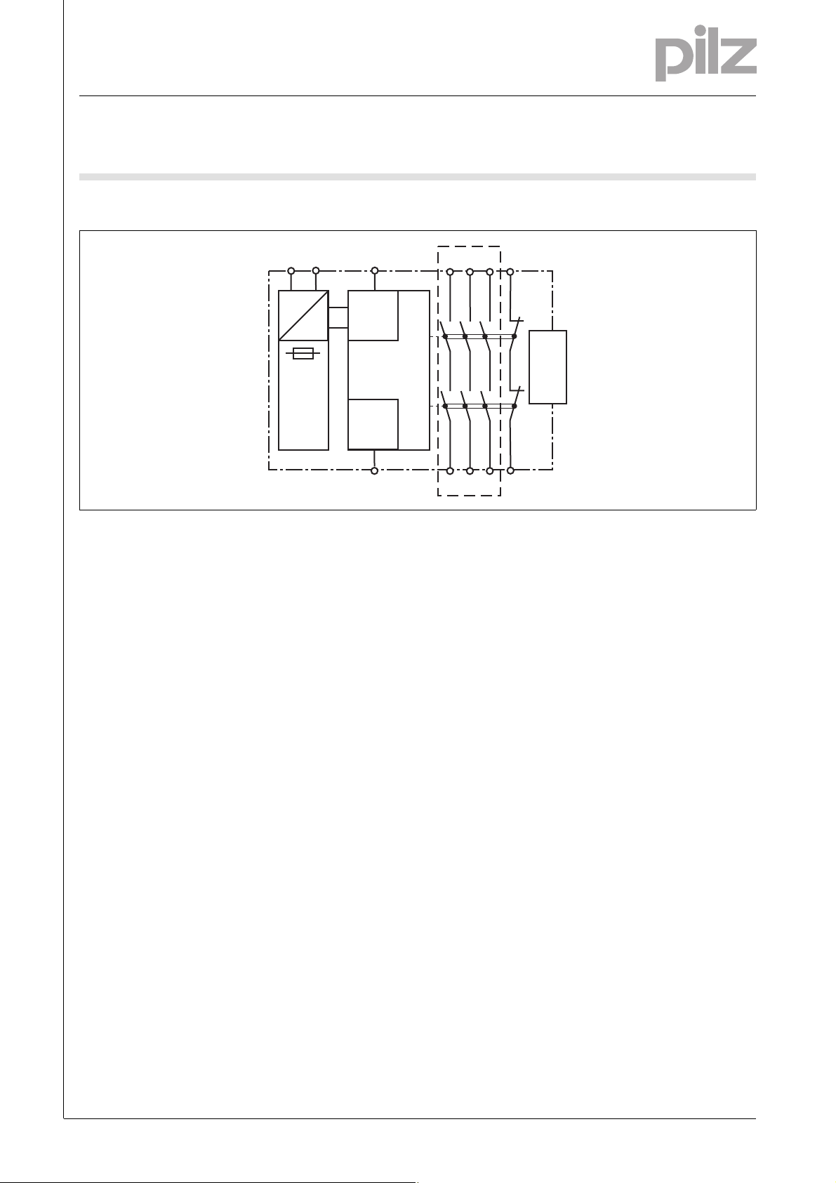
Block diagram
Blockschaltbild
A1 A2
][Blockschaltbild_nur sichere Trennung
S32
17
27
37
*
45
=
Input
=
Power
Reset
S34
*Safe separation in accordance with EN 60947-1, 6 kV
Function description
Funktionsbeschreibung
` Delay-on de-energisation, not re-
triggerable
If the supply voltage at the input circuit is interrupted, the safety contacts will open once the set release
time has elapsed, even if the safety
function is cancelled during the delay time. The unit cannot be reactivated until the delay time has
elapsed.
` Delay-on de-energisation, retrig-
gerable
(only possible as a standalone application or with the PNOZsigma
base unit!)
If the supply voltage at the input circuit is interrupted, the safety contacts will open once the set release
time has elapsed.
If the safety function is cancelled
during the delay time (e.g. safety
gate closed), the unit will remain active.
` Pulse on switching on
The safety contacts close when
supply voltage is applied, the feedback loop is closed and finally the
input circuit is closed. The safety
contacts are reopened once the
pulse time has elapsed.
If the input circuit is opened for
more than 10 ms during the pulse
time, the safety contacts will open
immediately and the auxiliary contact will be closed.
` Delay-on energisation
The set delay time is started when
supply voltage is applied, the feedback loop is closed and finally the
input circuit is closed.
If the input circuit and feedback
loop are closed once the delay time
has elapsed, the safety contacts
will close and the auxiliary contact
will be opened.
If the input circuit is opened for
more than 10 ms, the safety contacts will open immediately and the
auxiliary contact will be closed.
Funktionsbeschreibung_Erweiterungsgerät
with PNOZsigma base unit:
` Dual-channel operation via
PNOZsigma connector
with other base units or without base
unit:
` Single-channel operation: one input
circuit affects the output relays
K1
K2
18
28 38 46
unit
base
Interface
NSG-D-2-400-2010-08
-2
Page 3

Safe timer relay/contact expansion modules
up to PL e of EN ISO 13849-1
PNOZ s9
Timing diagrams
Delay-on de-energisation, not retriggerable
Zeitdiagramm
1 2
POWER
Input
Output safe
Output aux.
Feedback
Key
` Power: Supply voltage
` Input: Input circuit S32
` Output safe: Safety contacts 17-18,
27-28, 37-38
` Output aux: Auxiliary contact 45-46
t1 tv
` Feedback: Feedback loop S34
: Switch-on delay
` t
1
: Delay time
` t
v
tvt1
` c: Delay-on de-energisation with
the time t
` d: No retriggering in the time t
v
v
Delay-on de-energisation, retriggerable
Zeitdiagramm
Key
` Power: Supply voltage
` Input: Input circuit S32
` Output safe: Safety contacts 17-18,
27-28, 37-38
` Output aux: Auxiliary contact 45-46
` Feedback: Feedback loop S34
: Switch-on delay
` t
1
` tv: Delay-on de-energisation
: Overall delay time
` t
ges
` c: Delay-on de-energisation with
the time t
v
` d: Retriggering in the time tv for
overall delay-on de-energisation
t
ges
POWER
Input
Output safe
Output aux.
Feedback
1 2
t1 tv
tv
tges
tv
t1
NSG-D-2-400-2010-08
Page 4

Safe timer relay/contact expansion modules
up to PL e of EN ISO 13849-1
PNOZ s9
Pulse on switching on
Zeitdiagramm
POWER
Output safe
Output aux.
Feedback
Key
` Power: Supply voltage
` Input: Input circuit S32
` Output safe: Safety contacts 17-18,
27-28, 37-38
` Output aux: Auxiliary contact 45-46
` Feedback: Feedback loop S34
1 2
Input
tw tw
t1 t1 t1
: Switch-on delay
` t
1
: Delay-on de-energisation
` t
2
t2
` tw: Pulse time
` c: Normal operating cycle
` d: Fault: Input circuit opened too
early
3 4
t < 10 ms
tv
` e: Fault: Feedback loop closed too
late
` f: Normal operating cycle with
supply interruption < 10 ms
Delay-on energisation
POWER
Output safe
Output aux.
Feedback
Key
` Power: Supply voltage
` Input: Input circuit S32
` Output safe: Safety contacts 17-18,
27-28, 37-38
` Output aux: Auxiliary contact 45-46
` Feedback: Feedback loop S34
Wiring
][Verdrahtung_Si_unverz_1Hi_unverz
Please note:
` Information given in the “Technical
details” must be followed.
` Outputs 17-18, 27-28, 37-38 are
safety contacts, output 45-46 is an
auxiliary contact (e.g. for display).
` To prevent contact welding, a fuse
should be connected before the
output contacts (see technical details).
Zeitdiagramm
1 2
Input
tv tvt2 tv
: Delay-on de-energisation
` t
2
` tv: Delay time
` c: Normal operating cycle
` d: Fault: Input circuit opened too
early
` Calculation of the max. cable runs
in the input circuit:
l
max
R
lmax
=
I
max
Rl / km
R
= max. overall cable resist-
lmax
ance (see technical details)
/km = cable resistance/km
R
l
3 4
t < 10 ms
tv
` e: Fault: Feedback loop closed too
late after t
elapsed
2
` f: Normal operating cycle with
supply interruption < 10 ms
` Use copper wire that can withstand
60/75 °C.
` Sufficient fuse protection must be
provided on all output contacts with
capacitive and inductive loads.
NSG-D-2-400-2010-08
-4
Page 5

Safe timer relay/contact expansion modules
up to PL e of EN ISO 13849-1
PNOZ s9
Preparing for operation
Betriebsbereitschaft herstellen PNOZs
` Supply voltage
Supply voltage AC DC
` 1-channel input circuit/feedback loop
Input circuit Input circuit Feedback circuit
Without base unit (standalone)
Base unit:
Safety relay PNOZ X
Base unit:
Safety relay PNOZelog; driven via semiconductor outputs
(24 VDC)
S32
A2
24 V DC
PNOZ X
0 V
24 V DC
PNOZelog
Output
0 V
A1
S32
S34
A2
A1
S32
S34
A2
S3
+24 V DC
0 V
PNOZs9
PNOZs9
PNOZs9
24 V DC
PNOZ X
feedback
loop
0 V
The inputs that evaluate the feedback loop
will depend on the base unit and application.
24 V DC
PNOZelog
feedback
loop
0 V
The inputs that evaluate the feedback loop
will depend on the base unit and application.
* PNOZ e1p only; all other PNOZelog safety
relays without delay-on de-energisation
with PNOZ s9
S32
S34
A1
A2
A1
A2
K5
S34
45
46
A2
S34
45
46
A2
K6
S3
PNOZs9
L+
L-
24 V DC
0 V
PNOZs9
*
NSG-D-2-400-2010-08
Page 6

Safe timer relay/contact expansion modules
up to PL e of EN ISO 13849-1
PNOZ s9
` 2-channel input circuit
The input circuit is connected and evaluated via the connector.
The input circuit is connected and evaluated via the connector.
` Application
without base unit
Base unit: Safety relays
PNOZ s3, PNOZ s4, PNOZ s5
PNOZ s3
PNOZ s4
PNOZ s5
S11
Interface
PNOZsigma
S34
Base unit: Two-hand control unit
PNOZ s6
S12
PNOZ s6
Interface
PNOZsigma
S34
PNOZ s9
PNOZ s9
Base unit: Safety relays
PNOZ s1, PNOZ s2
PNOZ s1
PNOZ s2
Base unit: Two-hand control unit
PNOZ s6.1
S24
PNOZ s6.1
without feedback loop with feedback loop
PNOZs9
S32
S34
A1
A2
S3
24 V DC
0 V
PNOZs9
S32
S34
A1
A2
Interface
PNOZsigma
Interface
PNOZsigma
K5
A1
S34
S34
24 V DC
PNOZ s9
PNOZ s9
S3
K6
24 V DC
0 V
` Key
S3 Reset button
NSG-D-2-400-2010-08
-6
Page 7

Safe timer relay/contact expansion modules
up to PL e of EN ISO 13849-1
PNOZ s9
Terminal configuration
Klemmenbelegung
Installation
][Montage_PNOZsigma Erweiterungsgert
Install contact expander module
without base unit:
` Ensure that the plug terminator is
inserted at the side of the unit.
Connect base unit and PNOZsigma
contact expander module:
` Remove the plug terminator at the
side of the base unit and at the contact expander module
` Connect the base unit and the con-
tact expander module to the supplied connector before mounting
the units to the DIN rail.
Installation in control cabinet
` The safety relay should be installed
in a control cabinet with a protection type of at least IP54.
` Use the notch on the rear of the unit
to attach it to a DIN rail (35 mm).
` When installed vertically: Secure
the unit by using a fixing element
(e.g. retaining brakket or end angle).
` Push the unit upwards or down-
wards before lifting it from the DIN
rail.
Dimensions
Abmessungen
*with spring-loaded terminals
* 100 (3,94")
98 (3.86")
120 (4.72")
17,5
(0.69")
NSG-D-2-400-2010-08
Page 8

Safe timer relay/contact expansion modules
up to PL e of EN ISO 13849-1
PNOZ s9
NOTICE
][WICHTIG_PDB_alt
This data sheet is only intended for use
during configuration. For installation
Service life graph
10000
and operation, please refer to the operating instructions supplied with the
3
unit.
3
3
D Schaltspielzahl x 10
GB Cycles x 103F Nombre de manvres x 10
Technische Daten
Technical details
Electrical data
Supply voltage
Supply voltage U
DC 24 V
B
Voltage tolerance -20 %/+20 %
Power consumption at U
DC 2.0 W
B
Residual ripple DC 20 %
Typ. supply current at A1 70 mA
Voltage and current at
Input circuit DC: 15.0 mA
Feedback loop DC: 24.0 V 15.0 mA
Max. inrush current impulse
A1 0.70 A
Input circuit 0.10 A
Feedback loop 0.10 A
Number of output contacts
Safety contacts (N/O), delayed: 3
Auxiliary contacts (N/C), delayed: 1
Utilisation category in accordance with EN 60947-4-1
Safety contacts: AC1 at 240 V I
Safety contacts: DC1 at 24 V I
Auxiliary contacts: AC1 at 240 V I
Auxiliary contacts: DC1 at 24 V I
Utilisation category in accordance with EN 60947-5-1
Safety contacts: AC15 at 230 V I
Safety contacts: DC13 at 24 V (6 cycles/min) I
Auxiliary contacts: AC15 at 230 V I
Auxiliary contacts: DC13 at 24 V (6 cycles/min) I
Conventional thermal current 6.0 A
1000
3
100
E Número de ciclos x 103I Numero dei cicli di commutazione x 10
NL Aantal schakelingen x 10
10
D Nennbetriebstrom (A)
GB Nominal operating current (A)
Courant coupé (A)
F
min
P
min
P
min
P
min
P
max
max
max
max
0.5 1 2 3 4 5 6 7 8 9 10
: 0.01 A , I
: 1500 VA
max
: 0.01 A , I
: 150 W
max
: 0.01 A , I
: 1500 VA
max
: 0.01 A , I
: 150 W
max
: 5.0 A
: 5.0 A
: 5.0 A
: 5.0 A
max
max
max
max
Lebensdauerkurve
: 6.0 A
: 6.0 A
: 6.0 A
: 6.0 A
DC-1: 24V
AC-1: 230V
DC-13: 24V
E Corriente nominal de servicio (A)
I Corrente di esercizio nominale (A)
NL Nominale bedrijfsstroom (A)
AC-15: 230V
NSG-D-2-400-2010-08
-8
Page 9

Safe timer relay/contact expansion modules
up to PL e of EN ISO 13849-1
PNOZ s9
Electrical data
Contact material AgCuNi + 0.2 µm Au
External contact fuse protection (I
Blow-out fuse, quick
Safety contacts: 10 A
Auxiliary contacts: 10 A
Blow-out fuse, slow
Safety contacts: 6 A
Auxiliary contacts: 6 A
Circuit breaker 24 VAC/DC, characteristic B/C
Safety contacts: 6 A
Auxiliary contacts: 6 A
Max. overall cable resistance R
A1/A2 20 Ohm
Input circuit 30 Ohm
Feedback loop 30 Ohm
Safety-related characteristic data
PL in accordance with EN ISO 13849-1 PL e (Cat. 4)
Category in accordance with EN 954-1 Cat. 4
SIL CL in accordance with EN IEC 62061 SIL CL 3
PFH in accordance with EN IEC 62061 2.34E-09
SIL in accordance with IEC 61511 SIL 3
PFD in accordance with IEC 61511 2.75E-05
t
in years 20
M
Times
Switch-on delay
with manual reset typ. 60 ms
with manual reset max. 80 ms
Delay-on de-energisation
with E-STOP typ. 40 ms
with E-STOP max. 50 ms
Recovery time at max. switching frequency 1/s
after power failure 800 ms
Delay time t
Repetition accuracy +/- 1% + +/-20ms
Repetition accuracy in the case of a fault +/- 15% + +/-20ms
Time accuracy +/- 1% + +/-20ms
upply interruption before de-energisation 10 ms
S
Supply interruption before de-energisation in the input circuit 10.0 ms
Environmental data
EMC EN 60947-5-1, EN 61000-6-2, EN 61000-6-4
Vibration to EN 60068-2-6
Frequency 10 - 55 Hz
Amplitude 0.35 mm
Climatic suitability EN 60068-2-78
Airgap creepage in accordance with EN 60947-1
Pollution degree 2
Overvoltage category III
Rated insulation voltage 250 V
Rated impulse withstand voltage 6.00 kV
Ambient temperature -15 - 55 °C
Storage temperature -40 - 85 °C
: selectable 0,00 s; 0,10 s; 0,20 s; 0,30 s; 0,40 s; 0,50 s; 0,60 s; 0,70 s; 0,80 s;
V
= 1 kA) to EN 60947-5-1
K
lmax
1,00 s; 1,50 s; 2,00 s; 2,50 s; 3,00 s; 3,50 s; 4,00 s; 5,00 s; 6,00 s;
7,00 s; 8,00 s; 10,00 s; 12,00 s; 14,00 s; 15,00 s; 16,00 s; 20,00 s;
25,00 s; 30,00 s; 35,00 s; 40,00 s; 50,00 s; 60,00 s; 70,00 s; 80,00
s; 90,00 s; 100,00 s; 120,00 s; 140,00 s; 150,00 s; 160,00 s;
180,00 s; 200,00 s; 210,00 s; 240,00 s; 300,00 s
NSG-D-2-400-2010-08
Page 10

Safe timer relay/contact expansion modules
up to PL e of EN ISO 13849-1
PNOZ s9
Environmental data
Protection type
Mounting (e.g. cabinet) IP54
Housing IP40
Terminals IP 20
Mechanical data
Housing material
Housing PC
Front PC
Cross section of external conductors with screw terminals
1 core flexible 0.25 - 2.50 mm² , 24 - 12 AWG No. 750109
2 core, same cross section, flexible:
with crimp connectors, without insulating sleeve 0.25 - 1.00 mm² , 24 - 16 AWG No. 750109
without crimp connectors or with TWIN crimp connectors 0.20 - 1.50 mm² , 24 - 16 AWG No. 750109
Torque setting with screw terminals 0.50 Nm No. 750109
Cross section of external conductors with spring-loaded termi-
nals: Flexible with/without crimp connectors
Spring-loaded terminals: Terminal points per connection 2 No. 751109, 751189
Stripping length 9 mm No. 751109, 751189
Dimensions
Height 100.0 mm No. 751109, 751189
Width 17.5 mm
Depth 120.0 mm
Weight 175 g
Technische Daten_Satz No .
No. stands for order number.
Technische Daten_Satz No rmen
The standards current on 2007-02 apply.
Bestelldaten
0.20 - 2.50 mm² , 24 - 12 AWG No. 751109, 751189
96.0 mm No. 750109
Order reference
Type Features Terminals Order no.
PNOZ s9 24 VDC With screw terminals 750 109
PNOZ s9 C 24 VDC With spring-loaded terminals 751 109
PNOZ s9 C
(coated version)
24 VDC With spring-loaded terminals 751 189
NSG-D-2-400-2010-08
-10
 Loading...