

Page 1

21397-3FR-07
PNOZ s5
4 D Betriebsanleitung
4 GB Operating instructions
4 F Manuel d'utilisation
21397-3FR-07PNOZ s5
Sicherheitsschaltgerät PNOZ s5
582400011
Das Sicherheitsschaltgerät dient dem sicherheitsgerichteten Unterbrechen eines Sicherheitsstromkreises.
114371211
Das Sicherheitsschaltgerät erfüllt Forderungen
der EN 60947-5-1, EN 60204-1 und
VDE 0113-1 und darf eingesetzt werden in Anwendungen mit
` Not-Halt-Tastern
` Schutztüren
` Lichtschranken
Zu Ihrer Sicherheit
547263243
` Installieren und nehmen Sie das Gerät nur
dann in Betrieb, wenn Sie diese Betriebsanleitung gelesen und verstanden haben und
Sie mit den geltenden Vorschriften über Arbeitssicherheit und Unfallverhütung vertraut
sind.
Beachten Sie die VDE- sowie die örtlichen
Vorschriften, insbesondere hinsichtlich
Schutzmaßnahmen
` Durch Öffnen des Gehäuses oder eigen-
mächtige Umbauten erlischt jegliche Gewährleistung.
Gerätemerkmale
470135947
` Relaisausgänge zwangsgeführt:
– 2 Sicherheitskontakte (S) unverzögert
– 2 Sicherheitskontakte (S) rückfallverzögert
` 1 Halbleiterausgang
` Anschlussmöglichkeiten für:
– Not-Halt-Taster
– Schutztürgrenztaster
– Starttaster
– Lichtschranken
– PSEN
` 1 Kontakterweiterungsblock PNOZsigma
über Verbindungsstecker anschließbar
` Rückfallverzögerung einstellbar
` Betriebsarten und Verzögerungszeiten mit
Drehschaltern einstellbar
` LED-Anzeige für:
– Versorgungsspannung
– Eingangszustand Kanal 1
– Eingangszustand Kanal 2
– Schaltzustand Kanal 1/2
–Startkreis
–Fehler
` steckbare Anschlussklemmen (wahlweise
Federkraftklemme oder Schraubklemme)
Sicherheitseigenschaften
117575307
Das Schaltgerät erfüllt folgende Sicherheitsanforderungen:
` Die Schaltung ist redundant mit Selbstüber-
wachung aufgebaut.
` Die Sicherheitseinrichtung bleibt auch bei
Ausfall eines Bauteils wirksam.
` Bei jedem Ein-Aus-Zyklus der Maschine wird
automatisch überprüft, ob die Relais der Sicherheitseinrichtung richtig öffnen und
schließen.
114378891
` Das Gerät hat eine elektronische Sicherung.
PNOZ s5 safety relay
The safety relay provides a safety-related interruption of a safety circuit.
The safety relay meets the requirements of
EN 60947-5-1, EN 60204-1 and VDE 0113-1
and may be used in applications with
` E-STOP pushbuttons
` Safety gates
` Light beam devices
For your safety
Only install and commission the unit if you
`
have read and understood these operating
instructions and are familiar with the applicable regulations for health and safety at work
and accident prevention.
Ensure VDE and local regulations are met,
especially those relating to safety.
` Any guarantee is rendered invalid if the hous-
ing is opened or unauthorised modifications
are carried out.
Unit features
` Positive-guided relay outputs:
– 2 safety contacts (N/O), instantaneous
– 2 safety contacts (N/O), delay-on de-ener-
gisation
` 1 semiconductor output
` Connection options for:
– E-STOP pushbutton
– Safety gate limit switch
– Reset button
– Light barriers
–PSEN
` A connector can be used to connect 1
PNOZsigma contact expander module
` Delay-on de-energisation selectable
` Operating modes and delay times can be se-
lected via rotary switches
` LED indicator for:
– Supply voltage
– Input status, channel 1
– Input status, channel 2
– Switch status channel 1/2
– Reset circuit
–Error
` Plug-in connection terminals (either spring-
loaded terminal or screw terminal)
Safety features
The relay meets the following safety requirements:
` The circuit is redundant with built-in self-
monitoring.
` The safety function remains effective in the
case of a component failure.
` The correct opening and closing of the safety
function relays is tested automatically in
each on-off cycle.
` The unit has an electronic fuse.
Bloc logique de sécurité PNOZ s5
Le bloc logique de sécurité sert à interrompre
en toute sécurité un circuit de sécurité.
Le bloc logique de sécurité satisfait aux exigences des normes EN 60947-5-1, EN 60204-1 et
VDE 0113-1 et peut être utilisé dans des applications avec des
` boutons-poussoirs de arrêt d'urgence
` protecteurs mobiles
` barrières immatérielles
Pour votre sécurité
Vous n'installerez l'appareil et ne le mettrez
`
en service qu'après avoir lu et compris le
présent manuel d'utilisation et vous être familiarisé avec les prescriptions en vigueur
sur la sécurité du travail et la prévention des
accidents.
Respectez les normes locales ou VDE, particulièrement en ce qui concerne la sécurité.
` L'ouverture de l'appareil ou sa modification
annule automatiquement la garantie.
Caractéristiques de l'appareil
` Sorties de relais à contact lié :
– 2 contacts de sécurité (F) instantanés
– 2 contacts de sécurité (F) temporisés à la
retombée
` 1 sortie statique
` Raccordements possibles pour :
– poussoir d'arrêt d'urgence
– interrupteur de position
– poussoir de réarmement
– barrières immatérielles
–PSEN
` Un bloc d'extension de contacts
PNOZsigma raccordable par l'intermédiaire
d'un connecteur enfichable
` Temporisation à la retombée réglable
` Modes de fonctionnement et temporisations
réglables par sélecteur
` LED de visualisation pour :
– tension d'alimentation
– Etat d'entrée canal 1
– Etat d'entrée canal 2
– état de commutation des canaux 1/2
– Circuit de réarmement
– Erreurs
` Borniers débrochables (au choix avec rac-
cordement à ressort ou à vis)
Caractéristiques de sécurité
Le relais satisfait aux exigences de sécurité
suivantes :
` La conception interne est redondante avec
une autosurveillance.
` Le dispositif de sécurité reste actif, même en
cas de défaillance d'un composant.
` L'ouverture et la fermeture correctes des re-
lais internes sont contrôlées automatiquement à chaque cycle marche/arrêt de la
machine.
` L'appareil est équipé d'une sécurité électro-
nique.
- 1 -
Page 2
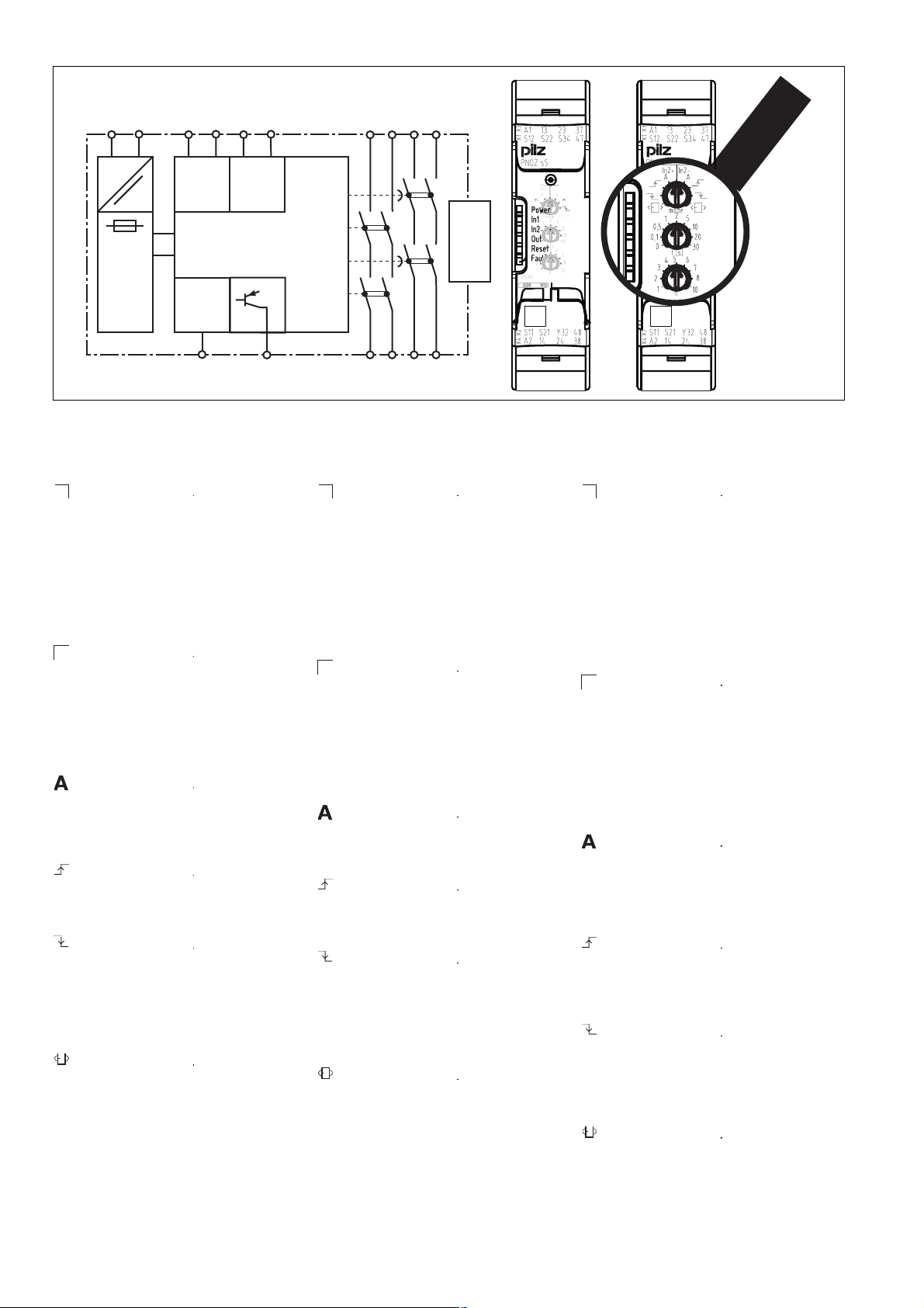
Blockschaltbild/Klemmenbelegung Block diagram/terminal configuration Schéma de principe
A1 A2
=
(~)*
( )*
=
S11 S12
S21 S22
InputInput
K3
13 23
37 47
K1
Power
Reset/
K4
K2
unit
Interface
expansion
Start
S34
*nur bei UB = 48 – 240 V AC/DC * only when UB = 48 – 240 VAC/DC * uniquement pour UB = 48 à 240 V AC
566336011
Mitte: Frontansicht mit Abdeckung
Rechts: Frontansicht ohne Abdeckung
Y32
Centre: Front view with cover
Right: Front view without cover
14 24
38 48
Schéma du milieu : vue frontale avec capot de
protection
A droite : vue frontale sans capot de protection
Funktionsbeschreibung
547279627
` Einkanaliger Betrieb: keine Redundanz
In2+
im Eingangskreis, Erdschlüsse im Startkreis und Eingangskreis werden erkannt.
` Zweikanaliger Betrieb ohne Querschlus-
serkennung: redundanter Eingangskreis,
erkennt
– Erdschlüsse im Start- und Eingangs-
kreis,
– Kurzschlüsse im Eingangskreis und
bei überwachtem Start auch im Startkreis.
550687755
` Zweikanaliger Betrieb mit Querschlus-
In2-
serkennung: redundanter Eingangskreis,
erkennt
– Erdschlüsse im Start- und Eingangs-
kreis,
– Kurzschlüsse im Eingangskreis und
bei überwachtem Start auch im Startkreis,
– Querschlüsse im Eingangskreis.
550690059
` Automatischer Start: Gerät wird aktiv,
nachdem Eingangskreis geschlossen
wurde.
` Manueller Start: Gerät wird aktiv, wenn
der Eingangskreis geschlossen ist und
danach der Startkreis geschlossen wird.
463145099
` Überwachter Start mit steigender Flanke:
Gerät wird aktiv, wenn der Eingangskreis
geschlossen ist und nach Ablauf der
Wartezeit (s. techn. Daten) der Startkreis
geschlossen wird.
457338123
` Überwachter Start mit fallender Flanke:
Gerät wird aktiv, wenn
– der Eingangskreis geschlossen ist und
danach der Startkreis geschlossen
und wieder geöffnet wird.
–der Startkreis geschlossen und nach
Schließen des Eingangskreises wieder
geöffnet wird.
419458699
` Start mit Anlauftest: Das Gerät prüft, ob
nach Anlegen der Versorgungsspannung
geschlossene Schutztüren geöffnet und
wieder geschlossen werden.
1047578379
` Kontaktvervielfältigung und –verstärkung der
– unverzögerten Sicherheitskontakte durch
Anschluss eines Kontakterweiterungsblocks PNOZsigma über Verbindungsstecker
– verzögerten/unverzögerten Sicherheits-
kontakte durch Verdrahtung von
Kontakterweiterungsblöcken oder externen Schützen möglich
Function description
Single-channel operation: no redundan-
`
In2+
cy in the input circuit, earth faults in the
reset circuit and input circuit are detected.
` Dual-channel operation without detec-
tion of shorts across contacts: redundant input circuit, detects
– earth faults in the reset and input cir-
cuit,
– short circuits in the input circuit and,
with a monitored reset, in the reset circuit too.
` Dual-channel operation with detection of
In2-
shorts across contacts: redundant input
circuit, detects
– earth faults in the reset and input cir-
cuit,
– short circuits in the input circuit and,
with a monitored reset, in the reset circuit too,
– shorts between contacts in the input
circuit.
` Automatic reset: Unit is active once the
input circuit has been closed.
` Manual reset: Unit is active once the in-
put circuit is closed and then the reset
circuit is closed.
` Monitored reset with rising edge: Unit is
active once the input circuit is closed and
once the reset circuit is closed after the
waiting period has elapsed
(see technical details).
` Monitored reset with falling edge: Unit is
active once
– the input circuit is closed and then the
reset circuit is closed and opened
again.
– the reset circuit is closed and then
opened again once the input circuit is
closed.
` Reset with start-up test: The unit checks
whether safety gates that are closed are
opened and then closed again when
supply voltage is applied.
` Ability to increase the number of contacts
available on the
– instantaneous safety contacts by using
connectors to link to a PNOZsigma contact expansion module
– delayed/instantaneous safety contacts by
connecting contact expansion modules or
external contactors
Description du fonctionnement
Commande par 1 canal : pas de redon-
`
In2+
dance dans le circuit d'entrée, les mises
à la terre dans les circuits de réarmement
et d'entrée sont détectés
` 2 canaux d'entrée sans détection des
court-circuits : circuit d'entrée redondant; sont détecté
– les mises à la terre dans le circuit de
réarmement et le circuit d'entrée;
– les courts-circuits dans le circuit d'en-
trée ainsi que dans le circuit de réarmement lors d'un réarmement autocontrôlé.
` 2 canaux d'entrée avec détection des
In2-
court-circuits : circuit d'entrée redondant; sont détectés
– les mises à la terre dans le circuit de
réarmement et le circuit d'entrée;
– les courts-circuits dans le circuit d'en-
trée ainsi que dans le circuit de réarmement lors d'un réarmement autocontrôlé;
– les courts-circuits entre les circuits
d'entrée.
` Réarmement automatique : l'appareil est
activé une fois que le circuit d'entrée est
fermé.
` Réarmement manuel : l'appareil est acti-
vé lorsque le circuit d'entrée est fermé et
après que le circuit de réarmement se
soit fermé.
` Réarmement auto-contrôlé avec front
montant : l'appareil est activé lorsque le
circuit d'entrée est fermé et lorsque le
circuit de réarmement se ferme après
l'écoulement du temps d'attente (voir les
caractéristiques techniques).
` Réarmement auto-contrôlé avec front
descendant : l'appareil est actif si
– le circuit d'entrée est fermé puis le cir-
cuit de réarmement fermé et réouvert.
– le circuit de réarmement est fermé
puis réouvert après la fermeture du circuit d'entrée.
` Réarmement avec test des conditions in-
itiales : l'appareil contrôle, après l'application de la tension d'alimentation, si les
protecteurs mobiles fermés sont ouverts
puis refermés.
- 2 -
Page 3

Montage
419461003
Grundgerät ohne Kontakterweiterungsblock montieren:
` Stellen Sie sicher, dass der Abschlussstek-
ker seitlich am Gerät gesteckt ist.
Grundgerät und Kontakterweiterungsblock
PNOZsigma verbinden:
` Entfernen Sie den Abschlussstecker seitlich
am Grundgerät und am Kontakterweiterungsblock.
` Verbinden Sie das Grundgerät und den Kon-
takterweiterungsblock mit dem mitgelieferten Verbindungsstecker bevor Sie die Geräte
auf der Normschiene montieren.
Montage im Schaltschrank
` Montieren Sie das Sicherheitsschaltgerät in
einen Schaltschrank mit einer Schutzart von
mindestens IP54.
` Befestigen Sie das Gerät mit Hilfe des Rast-
elements auf der Rückseite auf einer Normschiene (35 mm).
` Bei senkrechter Einbaulage: Sichern Sie das
Gerät durch ein Halteelement (z. B. Endhalter
oder Endwinkel).
` Vor dem Abheben von der Normschiene das
Gerät nach oben oder unten schieben.
Verdrahtung
117585931
Beachten Sie:
` Angaben im Abschnitt „Technische Daten“
unbedingt einhalten.
` Die Ausgänge 13-14, 23-24 sind unverzöger-
te Sicherheitskontakte, die Ausgänge 37-38,
47-48 sind rückfallverzögerte Sicherheitskontakte.
` Vor die Ausgangskontakte eine Sicherung
(s. techn. Daten) schalten, um das Verschweißen der Kontakte zu verhindern.
` Berechnung der max. Leitungslänge I
Eingangskreis:
R
lmax
=
I
max
Rl / km
R
= max. Gesamtleitungswiderstand
lmax
max
im
(s. techn. Daten)
/ km = Leitungswiderstand/km
R
l
` Leitungsmaterial aus Kupferdraht mit einer
Temperaturbeständigkeit von 60/75 °C verwenden.
` Sorgen Sie an allen Ausgangskontakten bei
kapazitiven und induktiven Lasten für eine
ausreichende Schutzbeschaltung.
583577611
` Bei U
1232919051
` Sorgen Sie beim Anschluss von magnetisch
48 – 240 V AC/DC: S21 mit Schutzlei-
B
tersystem verbinden
wirkenden, auf Reedkontakten basierenden
Näherungsschaltern dafür, dass der max.
Einschaltspitzenstrom (am Eingangskreis)
den Näherungsschalter nicht überlastet.
Installation
Install base unit without contact expander
module:
` Ensure that the plug terminator is inserted at
the side of the unit.
Connect base unit and PNOZsigma contact
expander module:
` Remove the plug terminator at the side of the
base unit and at the contact expander module.
` Connect the base unit and the contact ex-
pander module to the supplied connector
before mounting the units to the DIN rail.
Installation in control cabinet
` The safety relay should be installed in a con-
trol cabinet with a protection type of at least
IP54.
` Use the notch on the rear of the unit to attach
it to a DIN rail (35 mm).
` When installed vertically: Secure the unit by
using a fixing element (e.g. retaining bracket
or end angle).
` Push the unit upwards or downwards before
lifting it from the DIN rail.
Wiring
Please note:
` Information given in the “Technical details”
must be followed.
` Outputs 13-14, 23-24 are instantaneous
safety contacts, outputs 37-38, 47-48 are
delay-on de-energisation safety contacts.
` To prevent contact welding, a fuse should be
connected before the output contacts (see
technical details).
` Calculation of the max. cable runs l
input circuit:
R
lmax
=
I
max
Rl / km
= max. overall cable resistance (see
R
lmax
max
in the
technical details)
/ km = cable resistance/km
R
l
` Use copper wire that can withstand
60/75 °C.
` Sufficient fuse protection must be provided
on all output contacts with capacitive and inductive loads.
` With U
48 – 240 VAC/DC: Connect S21 to
B
the protective earth system
` When connecting magnetically operated,
reed proximity switches, ensure that the
max. peak inrush current (on the input circuit)
does not overload the proximity switch.
` Augmentation et renforcement du
– nombre de contacts de sécurité instanta-
nés par le raccordement d'un bloc d'extension de contacts PNOZsigma par le
biais d'un connecteur
– nombre de contacts de sécurité tempori-
sés ou instantanés par le câblage d'un
bloc d'extension de contacts ou de contacteurs externes
Montage
Installer l'appareil de base sans bloc d'extension de contacts :
` Assurez-vous que la fiche de terminaison est
insérée sur le côté de l'appareil.
Raccorder l'appareil de base et le bloc d'extension de contacts PNOZsigma :
` Retirez la fiche de terminaison sur le côté de
l'appareil de base et sur le bloc d'extension
de contacts.
` Avant de monter les appareils sur le rail DIN,
reliez l'appareil de base et le bloc d'extension de contacts à l'aide du connecteur fourni.
Montage dans une armoire
` Montez le bloc logique de sécurité dans une
armoire électrique ayant un indice de protection d'au moins IP54.
` Montez l'appareil sur un rail DIN à l'aide du
système de fixation situé sur la face arrière
(35 mm).
` Si l'appareil est monté à la verticale : sécuri-
sez-le à l'aide d'un élément de maintien
(exemple : support terminal ou équerre terminale).
` Avant de retirer l'appareil du rail DIN, pous-
sez l'appareil vers le haut ou vers le bas.
Raccordement
Important :
` Respectez impérativement les données indi-
quées dans la partie "Caractéristiques techniques".
` Les sorties 13-14, 23-24 sont des contacts
de sécurité instantanés, les sorties 37-38,
47-48 sont des contacts de sécurité temporisés à la retombée.
` Protection des contacts de sortie par des fu-
sibles (voir les caractéristiques techniques)
pour éviter leur soudage.
` Calcul de la longueur de câble max. I
le circuit d'entrée :
R
lmax
=
I
max
Rl / km
= résistance max. de l'ensemble du
R
lmax
max
sur
câblage (voir les caractéristiques techniques)
/km = résistance du câblage/km
R
l
` Utilisez uniquement des fils de câblage en
cuivre résistant à des températures de 60/
75 °C.
` Assurez-vous du pouvoir de coupure des
contacts de sortie en cas de charges capacitives ou inductives.
` U
48 - 240 V AC/DC : Reliez S21 à la barre
B
de terre commune.
` Lors du raccordement de détecteurs de
proximité magnétiques, basés sur des contacts Reed, veuillez vous assurer que le courant de crête max. à la mise sous tension (sur
le circuit d'entrée) ne surcharge pas les détecteurs de proximité.
- 3 -
Page 4
Betriebsbereitschaft herstellen Preparing for operation Mettre l'appareil en mode de marche
Betriebsarten und Verzögerungszeit
599372811
Die Betriebsart und die Verzögerungszeit werden an den Drehschaltern am Gerät eingestellt.
Öffnen Sie dazu die Abdeckung auf der Frontseite des Geräts.
WICHTIG
Verstellen Sie die Drehschalter nicht während des Betriebs. Ansonsten erscheint
eine Fehlermeldung, die Sicherheitskontakte öffnen und das Gerät ist erst wieder
betriebsbereit, nachdem die Versorgungsspannung aus- und wieder eingeschaltet
wurde.
Operating modes and delay time
The operating mode and delay time are set via
the rotary switches on the unit. You can do this
by opening the cover on the front of the unit.
NOTICE
Do not adjust the rotary switch during operation, otherwise an error message will appear, the safety contacts will open and the
unit will not be ready for operation until the
supply voltage has been switched off and
then on again.
Modes de fonctionnement et temporisation
Le mode de fonctionnement et la temporisation
se règlent sur le sélecteur de l'appareil. Ouvrez
le capot de protection sur la face avant de l'appareil.
IMPORTANT
Ne modifiez pas le sélecteur en cours de
fonctionnement. Sinon, l'appareil signale
un défaut et les contacts de sécurité
s'ouvrent. L'appareil n'est alors prêt à refonctionner qu'après avoir coupé puis remis en marche la tension d'alimentation.
Betriebsarten einstellen
568192395
` Versorgungsspannung ausschalten.
` Betriebsart mit dem Betriebsartenwahlschal-
ter "mode" wählen.
` Wenn der Betriebsartenwahlschalter "mode"
auf der Grundstellung ist (senkrechte Position), erscheint eine Fehlermeldung.
Set operating modes
` Switch off supply voltage.
` Select operating mode via the operating
mode selector switch "mode".
` If the operating mode selector switch
"mode" is in its start position (vertical position), an error message will appear.
Régler le mode de fonctionnement
` Couper la tension d'alimentation.
` Sélectionner le mode de fonctionnement à
l'aide du sélecteur de mode de marche
«mode».
` Si le sélecteur de mode de marche « mode »
est positionné sur sa position de base (position verticale), l'appareil signale une erreur.
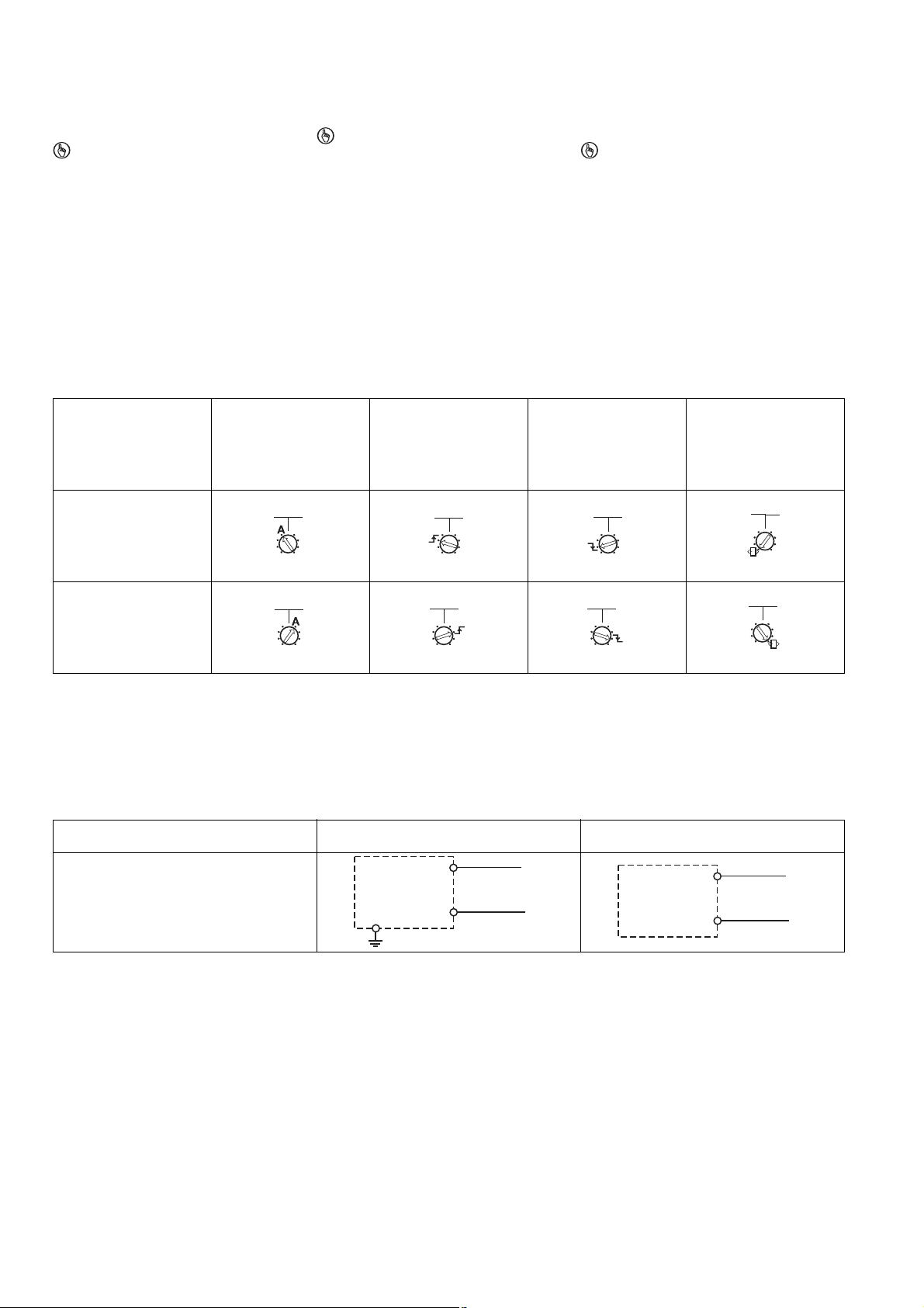
Betriebsartenwahlschalter
"mode"/
Operating mode selector
switch "mode"/
sélecteur de mode de marche "mode"
automatischer, manueller
Start/
automatic, manual reset/
réarmement automatique,
manuel
überwachter Start steigende Flanke/
monitored reset rising
edge/
réarmement auto-contrôlé
avec front montant
überwachter Start fallende
Flanke/
monitored reset falling
edge/
réarmement auto-contrôlé
avec front descendant
automatischer Start mit
Anlauftest/
automatic reset with startup test/
réarmement manuel avec
test des conditions initiales
ohne Querschlusserkennung/
without detection of shorts
In2+
In2-
In2+
In2-
In2+
In2-
across contacts/
sans détection des courtscircuits
mit Querschlusserkennung/
with detection of shorts
In2+
In2-
In2-
In2+
In2+
In2-
across contacts/
avec détection des courtscircuits
Verzögerungszeit einstellen
599376267
Zeitenwahlschalter "t[s]"
Faktorwahlschalter "n"
n x t[s] = Verzögerungszeit
Beispiel:
t = 4 s, n = 5
Verzögerungszeit = 5 x 4 = 20 s
Set delay time
Time selector switch "t[s]"
Factor selector switch "n"
n x t[s] = Delay time
Example:
t = 4 s, n = 5
Delay time = 5 x 4 = 20 s
Régler la temporisation
Sélecteur de temporisation « t[s] »
Sélecteur de facteurs « n »
n x t[s] = temporisation
Exemple :
t = 4 s, n = 5
Temporisation = 5 x 4 = 20 s
Anschluss Connection Raccordement
` Versorgungsspannung ` Supply voltage ` Tension d'alimentation
Versorgungsspannung/power supply/tension
d'alimentation
AC DC
A1
L
A1
In2+
In2+
In2-
In2-
L+
S21
A2
- 4 -
N
A2
L-
Page 5

` Eingangskreis ` Input circuit ` Circuit d'entrée
Eingangskreis/input circuit/circuit d'entrée einkanalig/single-channel /monocanal zweikanalig/dual-channel/à deux canaux
Not-Halt
ohne Querschlusserkennung/
E-STOP
without detection of shorts across contacts/
arrêt d'urgence
S11
S12
S22
sans détection des courts-circuits entre les
canaux
Not-Halt
mit Querschlusserkennung/
E-STOP
with detection of shorts across contacts/
arrêt d'urgence
avec détection des courts-circuits entre les
canaux
Schutztür
ohne Querschlusserkennung/
safety gate
without detection of shorts across contacts/
protecteur mobile
sans détection des courts-circuits entre les
canaux
S11
S12
S22
Schutztür
mit Querschlusserkennung/
safety gate
with detection of shorts across contacts/
protecteur mobile
avec détection des courts-circuits entre les
canaux
Lichtschranke oder Sicherheitsschalter
mit Querschlusserkennung durch BWS (nur
= 24 V DC)/
bei U
B
light barrier or safety switch
with detection of shorts across contacts via
ESPE (only when U
barrière immatérielle ou capteur de sécurité
= 24 V DC)/
B
avec détection des courts-circuits par EPES
(uniquement pour U
1017347979
*Die Spannung (24 V DC) an den Eingängen
verhindert das Öffnen der Sicherheitskontakte,
wenn die Versorgungsspannung an A1-A2 unterbrochen wird.
` Startkreis/Rückführkreis ` Reset circuit/feedback loop ` Circuit de réarmement/boucle de retour
Startkreis/Rückführkreis/
= 24 V DC)
B
*The voltage (24 VDC) at the inputs prevents the
safety contacts from opening if the supply voltage at A1-A2 is interrupted.
Startkreis/reset circuit/circuit de réarmement Rückführkreis/feedback loop/ boucle de rereset circuit/feedback loop/
circuit de réarmement/boucle de retour
automatischer Start/
automatic reset/
réarmement automatique
S12
S34
S1
S1
S1
S1
S1
S1
S2
S2
24 V DC *
GND
A2
S11
S12
S22
S11
S21
S22
S12
S11
S12
S22
S11
S12
S21
S22
S12
S22
*La tension (24 VDC) sur les entrées empêche
l'ouverture des contacts de sécurité lorsque la
tension d'alimentation est coupée sur A1-A2.
tour
S12
S34
13 (23,33,37,47)
14 (24,34,38,48)
K5
K6
K5
K6
L1
N
manueller/überwachter Start/
manual/monitored reset/
réarmement manuel/réarmement auto-contrôlé
S12
S34
S3
13 (23,33,37,47)
14 (24,34,38,48)
` Halbleiterausgang ` Semiconductor output ` Sortie statique
24 V DC UB 48 - 240 V AC/DC
U
B
*
Y32
584276491
*Verbinden Sie die 0-V-Anschlüsse aller externen Netzteile miteinander.
PLC Input
*Connect together the 0V connections on all
the external power supplies.
- 5 -
Y32
S21
* Reliez ensemble les 0 V de toutes les alimentations externes.
S12
S34
PLC Input
Gnd
K5
K6
K5
K6
S3
L1
N
Page 6

Betrieb
557883787
Das Gerät ist betriebsbereit, wenn die LED Power permanent leuchtet.
LEDs zeigen den Status und Fehler während
des Betriebs an:
LED leuchtet
LED blinkt
552061195
INFO
Statusanzeigen und Fehleranzeigen können unabhängig voneinander auftreten. Bei
einer Fehleranzeige leuchtet oder blinkt die
LED "Fault" (Ausnahme: "Versorgungsspannung zu gering"). Eine zusätzlich blinkende LED weist auf eine mögliche
Fehlerursache hin. Eine zusätzlich statisch
leuchtende LED weist auf einen normalen
Betriebszustand hin. Es können mehrere
Statusanzeigen und Fehleranzeigen gleichzeitig auftreten.
Statusanzeigen Status indicators Affichages d'état
551604875
Power
Versorgungsspannung liegt an.
551607179
In1
Eingangskreis an S12 ist geschlossen.
551609483
In2
Eingangskreis an S22 ist geschlossen.
551611787
Out
Sicherheitskontakte sind geschlossen und
Halbleiterausgang Y32 führt High-Signal.
551614091
Reset
An S34 liegt 24 V DC an.
599616011
Out
Eingestellte Verzögerungszeit läuft.
Fehleranzeigen Error indicators Affichage des erreurs
551771659
Alle LEDs aus
Diagnose: Querschluss/Erdschluss; Gerät
ausgeschaltet
` Abhilfe: Querschluss/Erdschluss behe-
ben, Versorgungsspannung für 1 Min.
ausschalten.
551773963
Fault
Diagnose: Abschlussstecker nicht gesteckt
` Abhilfe: Abschlussstecker stecken, Ver-
sorgungsspannung aus- und wieder einschalten.
551776267
Fault
Diagnose: Interner Fehler, Gerät defekt
` Abhilfe: Versorgungsspannung aus- und
wieder einschalten, gegebenenfalls Gerät tauschen.
551778571
Power
Diagnose: Versorgungsspannung zu gering
` Abhilfe: Versorgungsspannung überprü-
fen.
551780875
In1, In2 wechselweise
Fault
Diagnose: Querschluss zwischen S12 und
S22 erkannt
` Abhilfe: Querschluss beheben, Versor-
gungsspannung aus- und wieder einschalten.
552051979
In1
Fault
Diagnose: Einschaltblockade wegen Kurzzeitunterbrechung an S12; Eingangskreise
nicht gleichzeitig betätigt
` Abhilfe: Beide Eingangskreise, S12 und
S22 gleichzeitig öffnen und wieder
schließen.
552054283
In2
Fault
Diagnose: Einschaltblockade wegen Kurzzeitunterbrechung an S22; Eingangskreise
nicht gleichzeitig betätigt
` Abhilfe: Beide Eingangskreise, S12 und
S22 gleichzeitig öffnen und wieder
schließen.
Operation
The unit is ready for operation when the Power
LED is permanently lit.
LEDs indicate the status and errors during operation:
LED on
LED flashes
INFORMATION
Status indicators and error indicators may
occur independently. In the case of an error
display, the "Fault" LED will light or flash
(exception: "Supply voltage too low"). An
LED that is also flashing indicates the potential cause of the error. An LED that is lit
and is static indicates a normal operating
status. Several status indicators and error
indicators may occur simultaneously.
Power
Supply voltage is present.
In1
Input circuit at S12 is closed.
In2
Input circuit at S22 is closed.
Out
Safety contacts are closed and semiconductor output Y32 carries a high signal.
Reset
24 VDC is present at S34.
Out
Set delay time is running.
All LEDs off
Diagnostics: Short across contacts/earth
fault; unit switched off
` Remedy: Rectify short across contacts/
earth fault, switch off supply voltage for 1
min.
Fault
Diagnostics: Plug terminator not connected
` Remedy: Insert plug terminator, switch
supply voltage off and then on again.
Fault
Diagnostics: Internal error, unit defective
` Remedy: Switch supply voltage off and
then on again, change unit if necessary.
Power
Diagnostics: Supply voltage too low
` Remedy: Check the supply voltage.
In1, In2 alternately
Fault
Diagnostics: Short detected between S12
and S22
` Remedy: Rectify short across contacts,
switch supply voltage off and then on
again.
In1
Fault
Diagnostics: Power-up blocked due to
short-term interruption at S12; input circuits not operated simultaneously
` Remedy: Open both input circuits, S12
and S22, simultaneously and then close
again.
In2
Fault
Diagnostics: Power-up blocked due to
short-term interruption at S22; input circuits not operated simultaneously
` Remedy: Open both input circuits, S12
and S22, simultaneously and then close
again.
Exploitation
L'appareil est prêt à fonctionner lorsque la LED
Power reste allumée en permanence.
Les LEDs indiquent l'état et les erreurs lors du
fonctionnement:
LED allumée
LED clignotante
INFORMATION
L'affichage de l'état et des erreurs peut survenir indépendamment. Lors de l'affichage
d'une erreur, la LED "Fault" s'allume ou clignote (exception : "Tension d'alimentation
trop faible"). Une LED clignotante supplémentaire informe sur une cause possible
d'erreur. Une LED supplémentaire qui s'allume de façon permanente informe de l'état
normal de fonctionnement. Plusieurs affichages de l'état et des erreurs peuvent survenir en même temps.
Power
la tension d'alimentation est présente.
In1
Le circuit d'entrée S12 est fermé.
In2
Le circuit d'entrée S22 est fermé.
Out
Les contacts de sécurité sont fermés et la
sortie statique Y32 délivre un niveau haut.
Réarmement
24 V DC sur S34.
Out
La temporisation réglée fonctionne.
Toutes les LEDs sont éteintes
Diagnostic : court-circuit/mise à la terre ;
appareil éteint
` Remède : supprimer le court-circuit/la
mise à la terre, couper la tension d'alimentation pendant 1 min.
Fault
Diagnostic : fiche de terminaison non branchée
` Remède : brancher la fiche de terminai-
son, couper puis remettre en marche la
tension d'alimentation
Fault
Diagnostic : erreur interne, appareil défectueux
` Remède : couper puis remettre en mar-
che la tension d'alimentation, si besoin
échanger l'appareil
Power
Diagnostic : tension d'alimentation trop faible
` Remède : vérifier la tension d'alimenta-
tion
In1, In2 alternativement
Fault
Diagnostic : court-circuit entre S12 et S22
détecté
` Remède : Supprimer le court-circuit,
couper puis remettre en marche la tension d'alimentation
In1
Fault
Diagnostic : blocage du relais à cause
d'une coupure aléatoire sur S12 ; les canaux d'entrée n'ont pas commuté ensemble
` Remède : ouvrir ensemble les canaux
d'entrée S12 et S22 puis les refermer.
In2
Fault
Diagnostic : blocage du relais à cause
d'une coupure aléatoire sur S12 ; les canaux d'entrée n'ont pas commuté ensemble
` Remède : ouvrir ensemble les canaux
d'entrée S12 et S22 puis les refermer.
- 6 -
Page 7

552056587
Reset
Fault
Diagnose: Unerlaubte Stellung eines Drehschalters oder ein Drehschalter wurde während des Betriebs verstellt.
` Abhilfe: Versorgungsspannung aus- und
wieder einschalten.
552058891
Power, In1, In2, Out, Reset, Fault
Diagnose: Der Betriebsartenwahlschalter
"mode" steht in Grundstellung (senkrechte
Position)
` Abhilfe: Versorgungsspannung aus-
schalten und am Betriebsartenwahlschalter "mode" gewünschte Betriebsart
einstellen.
Fehler - Störungen
551266315
` Fehlfunktionen der Kontakte: Bei ver-
schweißten Kontakten ist nach Öffnen des
Eingangskreises keine neue Aktivierung
möglich.
Reset
Fault
Di agn ost ics: Pos iti on o f rotary swi tch is not
permitted or rotary switch was adjusted
during operation.
` Remedy: Switch supply voltage off and
then on again.
Power, In1, In2, Out, Reset, Fault
Diagnostics: The operating mode selector
switch "mode" is in its start position (vertical position)
` Remedy: Switch off the supply voltage
and set the required operating mode on
operating mode selector switch "mode".
Faults - malfunctions
Contact malfunctions: If the contacts have
`
welded, reactivation will not be possible after
the input circuit has opened.
Réarmement
Fault
Diagnostic : sélecteur rotatif dans une position incorrecte ou un sélecteur rotatif à été
déréglé durant le fonctionnement.
` Remède : couper puis remettre en mar-
che la tension d'alimentation.
Power, In1, In2, Out, Reset, Fault
Diagnostic : le sélecteur de mode de marche « mode » est positionné sur la position
de base (position verticale)
` Remède : coupez la tension d'alimenta-
tion et régler le mode de fonctionnement
souhaité sur le sélecteur de mode de
marche « mode ».
Erreurs - défaillances
Défaut de fonctionnement des contacts de
`
sortie : si les contacts sont soudés, un réarmement est impossible après ouverture du
circuit d'entrée.
Technische Daten Technical details Caractéristiques techniques
Elektrische Daten Electrical data Données électriques
Versorgungsspannung Supply voltage Tension d'alimentation
Versorgungsspannung U
Versorgungsspannung U
DC Supply voltage UB DC Tension d'alimentation UBDC 24 V
B
AC/DC Supply voltage UB AC/DC Tension d'alimentation UBAC/DC 48 - 240 V
B
Spannungstoleranz Voltage tolerance Plage de la tension d'alimentation -15 %/+10 %
Leistungsaufnahme bei U
Leistungsaufnahme bei U
AC Power consumption at UB AC Consommation UBAC 8,0 VA No. 750135, 751135
B
DC Power consumption at UB DC Consommation UBDC 4,0 W
B
Frequenzbereich AC Frequency range AC Plage de fréquences AC 50 - 60 Hz
Restwelligkeit DC Residual ripple DC Ondulation résiduelle DC 20 %, 160 %
Spannung und Strom an Voltage and current at Tension et courant sur
Eingangskreis DC: 24,0 V Input circuit DC: 24,0 V circuit d'entrée DC : 24,0 V 40,0 mA
Startkreis DC: 24,0 V Reset circuit DC: 24,0 V circuit de réarmement DC : 24,0 V 40,0 mA
Rückführkreis DC: 24,0 V Feedback loop DC: 24,0 V boucle de retour DC : 24,0 V 40,0 mA
Anzahl der Ausgangskontakte Number of output contacts Nombre de contacts de sortie
Sicherheitskontakte (S)
unverzögert:
Safety contacts (S) instantaneous: Contacts de sécurité (F)
instantanés :
2
Sicherheitskontakte (S) verzögert: Safety contacts (N/O), delayed: Contacts de sécurité (F) temporisés :2
Gebrauchskategorie nach
EN 60947-4-1
Sicherheitskontakte: AC1 bei 240 V Safety contacts: AC1 at 240 V Contacts de sécurité : AC1
Sicherheitskontakte: DC1 bei 24 V Safety contacts: DC1 at 24 V Contacts de sécurité : DC1 pour
Sicherheitskontakte verzögert: AC1
bei 240 V
Sicherheitskontakte verzögert: DC1
bei 24 V
Gebrauchskategorie nach
EN 60947-5-1
Sicherheitskontakte: AC15 bei
230 V
Sicherheitskontakte: DC13 bei 24 V
(6 Schaltspiele/min)
Sicherheitskontakte verzögert:
AC15 bei 230 V
Sicherheitskontakte verzögert:
DC13 bei 24 V (6 Schaltspiele/min)
Utilisation category in accordance
with EN 60947-4-1
Catégorie d'utilisation selon
EN 60947-4-1
pour 240 V
24 V
Safety contacts, delayed: AC1
at 240 V
Safety contacts, delayed: DC1
at 24 V
Utilisation category in accordance
with EN 60947-5-1
Contacts de sécurité temporisés :
AC1 pour 240 V
Contacts de sécurité temporisés :
DC1 pour 24 V
Catégorie d'utilisation selon
EN 60947-5-1
Safety contacts: AC15 at 230 V Contacts de sécurité : AC15
pour 230 V
Safety contacts: DC13 at 24 V
(6 cycles/min)
Safety contacts, delayed: AC15
at 230 V
Safety contacts, delayed: DC13
at 24 V (6 cycles/min)
Contacts de sécurité : DC13
pour 24 V (6 manœuvres/min)
Contacts de sécurité temporisés :
AC15 pour 230 V
Contacts de sécurité temporisés :
DC13 pour 24 V (6 manœuvres/min)
I
: 0,01 A , I
min
: 1500 VA
P
max
I
: 0,01 A , I
min
P
: 150 W
max
I
: 0,01 A , I
min
P
: 1500 VA
max
: 0,01 A , I
I
min
P
: 150 W
max
I
: 3,0 A
max
: 4,0 A
I
max
: 3,0 A
I
max
: 4,0 A
I
max
max
max
max
max
: 6,0 A
: 6,0 A
: 6,0 A
: 6,0 A
Kontaktmaterial Contact material Matériau des contacts AgCuNi + 0,2 µm Au
- 7 -
Page 8

Elektrische Daten Electrical data Données électriques
Kontaktabsicherung, extern
(I
= 1 kA) nach EN 60947-5-1
K
External contact fuse protection
(IK = 1 kA) to EN 60947-5-1
Protection des contacts en externe
(IK = 1 kA) selon EN 60947-5-1
Schmelzsicherung flink Blow-out fuse, quick Fusible rapide
Sicherheitskontakte: Safety contacts: Contacts de sécurité : 6 A
Sicherheitskontakte verzögert: Safety contacts, delayed: Contacts de sécurité temporisés : 6 A
Schmelzsicherung träge Blow-out fuse, slow Fusible normal
Sicherheitskontakte: Safety contacts: Contacts de sécurité : 4 A
Sicherheitskontakte verzögert: Safety contacts, delayed: Contacts de sécurité temporisés : 4 A
Sicherungsautomat 24V AC/DC,
Charakteristik B/C
Circuit breaker 24 VAC/DC, characteristic B/C
Disjoncteur 24 V AC/DC, caractéristique B/C
Sicherheitskontakte: Safety contacts: Contacts de sécurité : 4 A
Sicherheitskontakte verzögert: Safety contacts, delayed: Contacts de sécurité temporisés : 4 A
Halbleiterausgänge (kurz-
schlussfest)
Max. Gesamtleitungswiderstand
R
lmax
Eingangskreise, Startkreise
Semiconductor outputs (short circuit proof)
Max. overall cable resistance
R
lmax
input circuits, reset circuits
Sorties statiques (protégées contre
les courts-circuits)
Résistance max. de l'ensemble du
câblage R
circuits d'entrée, circuits de réar-
lmax
24,0 V DC, 20 mA
mement
einkanalig bei U
einkanalig bei U
zweikanalig ohne Querschlusser-
kennung bei U
zweikanalig ohne Querschlusser-
kennung bei U
zweikanalig mit Querschlusserken-
nung bei U
zweikanalig mit Querschlusserken-
nung bei U
Min. Eingangswiderstand im Ein-
schaltmoment
Sicherheitstechnische Kenndaten
PL nach EN ISO 13849-1: 2006 PL in accordance with
DC single-channel at UBDC monocanal pour UBDC 30 Ohm
B
AC single-channel at UBAC monocanal pour UBAC 30 Ohm No. 750135, 751135
B
DC
B
AC
B
DC
B
AC
B
dual-channel without detect. of
shorts across contacts at UBDC
dual-channel without detect. of
shorts across contacts at UBAC
dual-channel with detect. of shorts
across contacts at UBDC
dual-channel with detect. of shorts
across contacts at UBAC
Min. input resistance in the starting
torque
Safety-related characteristic
data
à deux canaux sans détection des
courts-circuits pour UBDC
à deux canaux sans détection des
courts-circuits pour UBAC
à deux canaux avec détection des
courts-circuits pour UBDC
à deux canaux avec détection des
courts-circuits pour UBAC
Résistance d'entrée min. au mo-
ment de la mise en marche
Caractéristiques techniques de
sécurité
30 Ohm
30 Ohm No. 750135, 751135
30 Ohm
30 Ohm No. 750135, 751135
110 Ohm
PL selon EN ISO 13849-1: 2006
EN ISO 13849-1: 2006
Sicherheitskontakte unverzögert Safety contacts, instantaneous Contacts de sécurité instantanés PL e (Cat. 4)
Sicherheitskontakte verzögert Sicherheitskontakte verzögert Sicherheitskontakte verzögert PL e (Cat. 4)
Kategorie nach EN 954-1 Category in accordance with
Catégorie selon EN 954-1
EN 954-1
Sicherheitskontakte unverzögert Safety contacts, instantaneous Contacts de sécurité instantanés Cat. 4
Sicherheitskontakte verzögert Sicherheitskontakte verzögert Sicherheitskontakte verzögert Cat. 4
SIL CL nach EN IEC 62061 SIL CL in accordance with
SIL CL selon EN IEC 62061
EN IEC 62061
Sicherheitskontakte unverzögert Safety contacts, instantaneous Contacts de sécurité instantanés SIL CL 3
Sicherheitskontakte verzögert Sicherheitskontakte verzögert Sicherheitskontakte verzögert SIL CL 3
PFH nach EN IEC 62061 PFH in accordance with
PFH selon EN IEC 62061
EN IEC 62061
Sicherheitskontakte unverzögert Safety contacts, instantaneous Contacts de sécurité instantanés 2,31E-09
Sicherheitskontakte verzögert Sicherheitskontakte verzögert Sicherheitskontakte verzögert 2,34E-09
SIL nach IEC 61511 SIL in accordance with IEC 61511 SIL selon IEC 61511
Sicherheitskontakte unverzögert Safety contacts, instantaneous Contacts de sécurité instantanés SIL 3
Sicherheitskontakte verzögert Sicherheitskontakte verzögert Sicherheitskontakte verzögert SIL 3
PFD nach IEC 61511 PFD in accordance with IEC 61511 PFD selon IEC 61511
Sicherheitskontakte unverzögert Safety contacts, instantaneous Contacts de sécurité instantanés 2,03E-06
Sicherheitskontakte verzögert Sicherheitskontakte verzögert Sicherheitskontakte verzögert 2,75E-05
t
in Jahren tM in years tM en années 20
M
- 8 -
Page 9

Zeiten Times Temporisations
Einschaltverzögerung Switch-on delay Temps de montée
bei automatischem Start typ. with automatic reset typ. pour un réarmement automatique
180 ms
env.
bei automatischem Start max. with automatic reset max. pour un réarmement automatique
400 ms
max.
bei automatischem Start nach
Netz-Ein typ.
bei automatischem Start nach
Netz-Ein max.
with automatic reset after power on
typ.
with automatic reset after power on
max.
pour un réarmement automatique
après mise sous tension env.
pour un réarmement automatique
après mise sous tension max.
1.430 ms
2.000 ms
bei manuellem Start typ. with manual reset typ. pour un réarmement manuel env. 45 ms
bei manuellem Start max. with manual reset max. pour un réarmement manuel max. 85 ms
bei überwachtem Start mit steigen-
der Flanke typ.
bei überwachtem Start mit steigen-
der Flanke max.
bei überwachtem Start mit fallender
Flanke typ.
bei überwachtem Start mit fallender
Flanke max.
on monitored reset with rising edge
typ.
on monitored reset with rising edge
max.
on monitored reset with falling edge
typ.
on monitored reset with falling edge
max.
pour un réarmement auto-contrôlé
avec front montant env.
pour un réarmement auto-contrôlé
avec front montant max.
pour un réarmement auto-contrôlé
avec front descendant env.
pour un réarmement auto-contrôlé
avec front descendant max.
45 ms
130 ms
60 ms
150 ms
Rückfallverzögerung Delay-on de-energisation Temps de retombée
bei Not-Halt typ. with E-STOP typ. sur un arrêt d'urgence env. 15 ms
bei Not-Halt max. with E-STOP max. sur un arrêt d'urgence max. 20 ms
bei Netzausfall typ. with power failure typ. sur coupure d'alimentation env. 75 ms
bei Netzausfall max. with power failure max. sur coupure d'alimentation max. 110 ms
Wiederbereitschaftszeit bei max.
Schaltfrequenz 1/s
Recovery time at max. switching
frequency 1/s
Temps de remise en service pour
une fréquence de commutation
max. de 1/s
nach Not-Halt after E-STOP après un arrêt d'urgence 150 ms +tv
nach Netzausfall after power failure après une coupure d'alimentation 200 ms
Verzögerungszeit t
: einstellbar Delay time tV: selectable Temporisation tV : réglable 0,00 s; 0,10 s; 0,20 s; 0,30 s;
V
0,40 s; 0,50 s; 0,60 s; 0,70 s;
0,80 s; 1,00 s; 1,50 s; 2,00 s;
2,50 s; 3,00 s; 3,50 s; 4,00 s;
5,00 s; 6,00 s; 7,00 s; 8,00 s;
10,00 s; 12,00 s; 14,00 s;
15,00 s; 16,00 s; 20,00 s;
25,00 s; 30,00 s; 35,00 s;
40,00 s; 50,00 s; 60,00 s;
70,00 s; 80,00 s; 90,00 s;
100,00 s; 120,00 s; 140,00 s;
150,00 s; 160,00 s; 180,00 s;
200,00 s; 210,00 s; 240,00 s;
300,00 s
Wiederholgenauigkeit Repetition accuracy Précision en reproductibilité -1 %/+1 %, -20 ms/+20 ms
Wiederholgenauigkeit im Fehlerfall Repetition accuracy in the case of a
fault
Précision en reproductibilité en cas
de défaut
-15 %/+15 %, -20 ms/+20 ms
Zeitgenauigkeit Time accuracy Précision temporelle -1 %/+1 %, -20 ms/+20 ms
Wartezeit bei überwachtem Start Waiting period with a monitored re-
set
Délai d'attente lors d'un réarmement auto-contrôlé
mit steigender Flanke with rising edge avec front montant 150 ms
mit fallender Flanke with falling edge avec front descendant 240 ms
Min. Startimpulsdauer bei über-
wachtem Start
Min. start pulse duration with a
monitored reset
Durée min. de l'impulsion de réarmement lors d'un réarmement
auto-contrôlé
mit steigender Flanke with rising edge avec front montant 30 ms
mit fallender Flanke with falling edge avec front descendant 70 ms
Gleichzeitigkeit Kanal 1 und 2 Simultaneity, channel 1 and 2 Simultanéité des canaux 1 et 2 ∞
Überbrückung bei Spannungsein-
brüchen der Versorgungsspannung
Supply interruption before de-energisation
Inhibition en cas de micro-coupures
de la tension d'alimentation
20 ms
Umweltdaten Environmental data Données sur l'environnement
EMV EMC CEM EN 60947-5-1, EN 61000-6-2,
EN 61000-6-4
Schwingungen nach EN 60068-2-6 Vibration to EN 60068-2-6 Vibrations selon EN 60068-2-6
Frequenz Frequency Fréquence 10 - 55 Hz
Amplitude Amplitude Amplitude 0,35 mm
Klimabeanspruchung Climatic suitability Sollicitations climatiques EN 60068-2-78
Luft- und Kriechstrecken nach
EN 60947-1
Airgap creepage in accordance
with EN 60947-1
Cheminement et claquage
selon EN 60947-1
Verschmutzungsgrad Pollution degree Niveau d'encrassement 2
Überspannungskategorie Overvoltage category Catégorie de surtensions III
Bemessungsisolationsspannung Rated insulation voltage Tension assignée d'isolement 250 V
Bemessungsstoßspannungsfestig-
keit
Rated impulse withstand voltage Tension assignée de tenue aux
chocs
4,00 kV
Umgebungstemperatur Ambient temperature Température d'utilisation -10 - 55 °C
- 9 -
Page 10

Umweltdaten Environmental data Données sur l'environnement
Lagertemperatur Storage temperature Température de stockage -40 - 85 °C
Schutzart Protection type Indice de protection
Einbauraum (z. B. Schaltschrank) Mounting (e.g. cabinet) Lieu d'implantation (par exemple :
IP54
armoire électrique)
Gehäuse Housing Boîtier IP40
Klemmenbereich Terminals Borniers IP20
Mechanische Daten Mechanical data Données mécaniques
Gehäusematerial Housing material Matériau du boîtier
Gehäuse Housing Boîtier PC
Front Front Face avant PC
Querschnitt des Außenleiters bei
Schraubklemmen
Cross section of external conductors with screw terminals
Capacité de raccordement des borniers à vis
1 Leiter flexibel 1 core flexible 1 câble flexible 0,25 - 2,50 mm² , 24 - 12 AWG
No. 750105, 750135
2 Leiter gleichen Querschnitts, flexibel:
mit Aderendhülse, ohne Kunststoffhülse
ohne Aderendhülse oder mit TWIN
Aderendhülse
Anzugsdrehmoment bei Schraubklemmen
Querschnitt des Außenleiters bei
Federkraftklemmen: flexibel mit/
ohne Aderendhülse
2 core, same cross section, flexible: 2 câbles flexibles de même
section :
with crimp connectors, without in-
avec embout, sans cosse plastique 0,25 - 1,00 mm² , 24 - 16 AWG
sulating sleeve
without crimp connectors or with
sans embout ou avec embout TWIN 0,20 - 1,50 mm² , 24 - 16 AWG
TWIN crimp connectors
Torque setting with screw terminals Couple de serrage des borniers à
vis
Cross section of external conductors with spring-loaded terminals:
Flexible with/without crimp connec-
Capacité de raccordement des borniers à ressort : flexible avec/sans
embout
No. 750105, 750135
No. 750105, 750135
0,50 Nm No. 750105, 750135
0,20 - 2,50 mm² , 24 - 12 AWG
No. 751105, 751135, 751185
tors
Federkraftklemmen: Klemmstellen
pro Anschluss
Spring-loaded terminals: Terminal
points per connection
Borniers à ressort : points de raccordement pour chaque borne
2 No. 751105, 751135, 751185
Abisolierlänge Stripping length Longueur dénudation 9 mm No. 751105, 751135,
751185
Abmessungen Dimensions Dimensions
Höhe Height Hauteur 102,0 mm No. 751105, 751135,
751185
96,0 mm No. 750105, 750135
Breite Width Largeur 22,5 mm
Tiefe Depth Profondeur 120,0 mm
Gewicht Weight Poids 235 g No. 750105, 751105,
751185
280 g No. 750135, 751135
No. ist gleichbedeutend mit Bestell-Nr. No. stands for order number. No. correspond à la référence du produit.
1176133131
ACHTUNG!
Beachten Sie unbedingt die Lebensdauerkurven der Relais. Die sicherheitstechnischen Kennzahlen der Relaisausgänge
gelten nur, solange die Werte der Lebens-
dauerkurven eingehalten werden.
Der PFH-Wert ist abhängig von der Schaltfrequenz und der Belastung des Relaisausganges.
Solange die Lebensdauerkurven nicht erreicht
werden, kann der angegebene PFH-Wert unabhängig von der Schaltfrequenz und der Belastung verwendet werden, da der PFH-Wert den
B10d-Wert der Relais sowie die Ausfallraten
der anderen Bauteile bereits berücksichtigt.
1077650443
Alle in einer Sicherheitsfunktion verwendeten
Einheiten müssen bei der Berechnung der Sicherheitskennwerte berücksichtigt werden.
585241611
CAUTION!
It is essential to consider the relay's service
life graphs. The relay outputs' safety-related characteristic data is only valid if the val-
ues in the service life graphs are met.
The PFH value depends on the switching frequency and the load on the relay output. If the
service life graphs are not accessible, the stated PFH value can be used irrespective of the
switching frequency and the load, as the PFH
value already considers the relay's B10d value
as well as the failure rates of the other components.
All the units used within a safety function must
be considered when calculating the safety
characteristic data.
The standards current on 2006-04 apply.
ATTENTION !
Veuillez absolument tenir compte des courbes de durée de vie des relais. Les caractéristiques de sécurité des sorties relais sont
uniquement valables tant que les valeurs
des courbes de durée de vie sont respec-
tées.
La valeur PFH dépend de la fréquence de commutat ion et de la charge de la sor tie relai s. Tan t
que les courbes de durée de vie ne sont pas atteintes, la valeur PFH indiquée peut être utilisée
indépendamment de la fréquence de commutation et de la charge car la valeur PFH prend
déjà en compte la valeur B10d des relais ainsi
que les taux de défaillance des autres composants.
Toutes les unités utilisées dans une fonction de
sécurité doivent être prises en compte dans le
calcul des caractéristiques de sécurité.
Es gelten die 2006-04 aktuellen Ausgaben der
Normen.
Les versions actuelles 2006-04 des normes
s'appliquent.
Konventioneller thermischer
Strom
Conventional thermal current Courant thermique
conventionnel
Ith(A) pro Kontakt bei UBDC Ith(A) at UBDC Ith(A) pour UBDC
1 Kontakt 1 contact 1 contact 6,00 A
2 Kontakte 2 contacts 2 contacts 6,00 A
3 Kontakte 3 contacts 3 contacts 6,00 A
4 Kontakte 4 contacts 4 contacts 6,00 A
- 10 -
Page 11

Lebensdauerkurve der Ausgangsrelais
1196936075
Die Lebensdauerkurven geben an, ab welcher
Schaltspielzahl mit verschleißbedingten Ausfällen gerechnet werden muss. Der Verschleiß
wird vor allem durch die elektrische Belastung
verursacht, der mechanische Verschleiß ist vernachlässigbar.
Service life graph of output relays
The service life graphs indicate the number of
cycles from which failures due to wear must be
expected. The wear is mainly caused by the
electrical load; the mechanical load is negligible.
Courbe de durée de vie du relais de sortie
Les courbes de durée de vie indiquent à partir
de quel nombre de manœuvres il faut s'attendre à des défaillances liées à l'usure. La charge
électrique est la cause principale de l'usure,
l'usure mécanique étant négligeable.
10
1
0.1
E Corriente nominal de servicio (A)
I Corrente di esercizio nominale (A)
NL Nominale bedrijfsstroom (A)
D Schaltspielzahl x 10
GB Cycles x 10
F Nombre de manuvres x 10
1205832331
D Nennbetriebstrom (A)
GB Nominal operating current (A)
F Courant coupé (A)
Beispiel
` Induktive Last: 0,2 A
` Gebrauchskategorie: AC15
` Lebensdauer der Kontakte: 700 000 Schalt-
spiele
Solange die zu realisierende Applikation eine
Schaltspielzahl von weniger als 700 000 Schaltspiele erfordert, kann mit dem PFH-Wert (s.
technische Daten) gerechnet werden.
Um die Lebensdauer zu erhöhen, an allen Ausgangskontakten für eine ausreichende Funkenlöschung sorgen. Bei kapazitiven Lasten sind
eventuell auftretende Stromspitzen zu beachten. Bei DC-Schützen Freilaufdioden zur Funkenlöschung einsetzen.
1209868299
Wir empfehlen zum Schalten von 24-V-DC-Lasten, Halbleiterausgänge zu verwenden.
10 100 1000 10000
Example
` Inductive load: 0.2 A
` Utilisation category: AC15
` Contact service life: 700 000 cycles
Provided the application requires fewer than
700 000 cycles, the PFH value (see technical
details) can be used in the calculation.
To increase the service life, sufficient spark
suppression must be provided on all output
contacts. With capacitive loads, any power
surges that occur must be noted. With contactors, use freewheel diodes for spark suppression.
We recommend you use semiconductor outputs to switch 24 VDC loads.
AC15: 230 V
DC13: 24 V
3
DC1: 24 V
AC1: 230 V
3
E Número de ciclos x 10
I Numero dei cicli di commutazione x 10
3
NL Aantal schakelingen x 10
3
3
Exemple
` Charge inductive : 0,2 A
` Catégorie d'utilisation : AC15
` Durée de vie des contacts : 700 000 manœu-
vres
Tant que l'application à réaliser requière un
nombre de manœuvres inférieur à 700 000, on
peut se fier à la valeur PFH (voir les caractéristiques techniques).
Assurez-vous qu'il y ait une extinction d'arc
suffisante sur tous les contacts de sortie afin
d'augmenter la durée de vie. Faites attention à
l'apparition de pointes de courant en cas de
charges capacitatives. En cas de contacteurs
DC, utilisez des diodes de roue libre pour l'extinction des étincelles.
Nous vous recommandons d'utiliser des sorties statiques pour la commutation de charges
de 24 V DC.
Bestelldaten Order reference Caractéristiques
Typ/
Type/
Type
PNOZ s5 24 V DC mit Schraubklemmen/
PNOZ s5 C 24 V DC mit Federkraftklemmen/
PNOZ s5 C
(coated version)
PNOZ s5 48 - 240 V AC 48 - 240 V DC mit Schraubklemmen/
PNOZ s5 C 48 - 240 V AC 48 - 240 V DC mit Federkraftklemmen/
Merkmale/
Features/
Caractéristiques
Klemmen/
Terminals/
Borniers
with screw terminals/
avec borniers à vis
with spring-loaded terminals/
avec borniers à ressort
24 V DC mit Federkraftklemmen/
with spring-loaded terminals/
avec borniers à ressort
with screw terminals/
avec borniers à vis
with spring-loaded terminals/
avec borniers à ressort
3
Bestell-Nr./
Order no./
Référence
750 105
751 105
751 185
750 135
751 135
EG-Konformitätserklärung
1139424011
Diese(s) Produkt(e) erfüllen die Anforderungen
der Richtlinie 2006/42/EG über Maschinen des
europäischen Parlaments und des Rates. Die
vollständige EG-Konformitätserklärung finden
Sie im Internet unter www.pilz.com.
Bevollmächtigter: Norbert Fröhlich, Pilz GmbH
& Co. KG, Felix-Wankel-Str. 2, 73760 Ostfildern, Deutschland
21397-3FR-07
EC Declaration of Conformity
This (these) product(s) comply with the requirements of Directive 2006/42/EC of the European
Parliament and of the Council on machinery.
The complete EC Declaration of Conformity is
available on the Internet at www.pilz.com.
Authorised representative: Norbert Fröhlich,
Pilz GmbH & Co. KG, Felix-Wankel-Str. 2,
73760 Ostfildern, Germany
- 11 -
Déclaration de conformité CE
Ce(s) produit(s) satisfait (satisfont) aux exigences de la directive 2006/42/CE relative aux machines du Parlement Européen et du Conseil.
Vous trouverez la déclaration de conformité CE
complète sur notre site internet www.pilz.com.
Représentant : Norbert Fröhlich, Pilz GmbH &
Co. KG, Felix-Wankel-Str. 2, 73760 Ostfildern,
Allemagne
Page 12

Originalbetriebsanleitung/Original instructions/Notice originale
21397-3FR-07, 2010-11 Printed in Germany Printed in Germany
 Loading...