

Page 1

Operating Manual PNOZ s30
Operating Manual PNOZ s30
PNOZ s30
Safety relays
Operating Manual — No. 1001715-EN-11
Page 2

This document is a translation of the original document.
All rights to this documentation are reserved by Pilz GmbH & Co. KG. Copies may be made
for internal purposes.
Suggestions and comments for improving this documentation will be gratefully received.
Pilz®, PIT®, PMI®, PNOZ®, Primo®, PSEN®, PSS®, PVIS®, SafetyBUS p®, SafetyEYE®,
SafetyNET p®, the spirit of safety® are registered and protected trademarks of
Pilz GmbH & Co. KG in some countries.
SD means Secure Digital.
Preface
Page 3

Contents
Contents
Contents Page
Chapter 1 Introduction
1.1 Validity of documentation 1-1
1.2 Overview of documentation 1-2
1.3 Definition of symbols 1-3
Chapter 2 Overview
2.1 Unit structure 2-1
2.1.1 Range 2-1
2.1.2 Unit features 2-1
2.2 Front/side view 2-2
Chapter 3 Safety
3.1 Intended use 3-1
3.2 Safety regulations 3-2
3.2.1 Use of qualified personnel 3-2
3.2.2 Warranty and liability 3-2
3.2.3 Disposal 3-2
3.2.4 For your safety 3-2
Chapter 4 Function description
4.1 Introduction 4-1
4.2 Block diagram 4-2
4.3 Functions 4-3
4.4 Speed configuration 4-7
4.4.1 Select Inputs 4-9
4.4.2 Switch functions 4-10
4.4.3 Basic configuration 4-11
4.4.4 Chip card 4-13
4.5 Input device types 4-14
4.5.1 Proximity switch 4-14
4.5.2 Rotary encoders 4-14
4.5.2.1 Adapter for incremental encoders 4-15
Chapter 5 Installation
5.1 General installation guidelines 5-1
5.1.1 Dimensions 5-1
Chapter 6 Commissioning
6.1 Wiring 6-1
6.1.1 General wiring guidelines 6-1
6.1.2 Pin assignment of RJ45 socket 6-1
6.1.3 Supply voltage 6-1
6.1.4 Connection of proximity switches 6-1
Pilz GmbH & Co. KG, Felix-Wankel-Straße 2, 73760 Ostfildern, Germany
Telephone: +49 711 3409-0, Telefax: +49 711 3409-133, E-Mail: pilz.gmbh@pilz.de
1
Page 4

Contents
6.1.5 Connection of a rotary encoder 6-2
6.1.5.1 Connect rotary encoder to speed monitor 6-2
6.1.5.2 Connect rotary encoder with Z index to
speed monitor
6.1.5.3 Connect rotary encoder to the speed monitor via an adapter
6.1.6 Connection of proximity switch and rotary
encoder
6.1.7 Reset circuit 6-5
6.1.8 Feedback circuit 6-5
6.1.9 Select inputs 6-6
6.1.10 Semiconductor outputs 6-6
6.2 Display menu - Configuration 6-7
6.2.1 Create configuration overview 6-7
6.2.2 Operate rotary knob 6-7
6.2.3 Configure Speed Monitor 6-8
6.2.4 Password protection 6-9
6.2.5 Use chip card 6-9
6.2.5.1 Insert chip card 6-10
6.2.5.2 Write data to chip card 6-11
6.2.5.3 Read data from chip card 6-11
6.2.5.4 Transfer device parameters 6-12
6.2.5.5 Duplicate chip card 6-12
6.2.6 Menu overview 6-12
6.2.6.1 Permanent display 6-12
6.2.6.2 Basic settings Ini pnp pnp 6-12
6.2.6.3 Basic settings for the rotary encoder 6-13
6.2.6.4 Settings 6-15
6.2.6.5 Advanced settings 6-20
6.2.6.6 Information 6-21
6.2.7 Example: Configure basic configuration 2 6-24
6-3
6-4
6-4
Chapter 7 Operation
7.1 Display elements for device diagnostics 7-1
7.1.1 LEDs 7-1
7.1.2 Display 7-1
7.1.2.1 Error stack entries 7-1
7.1.2.2 Current error messages 7-2
7.1.2.3 Open circuit message 7-6
7.1.2.4 Frequency difference message 7-7
Chapter 8 Technical details
8.1 Technical details 8-1
8.2 Service life graph of output relays 8-5
8.3 Categories 8-6
Pilz GmbH & Co. KG, Felix-Wankel-Straße 2, 73760 Ostfildern, Germany
2
Telephone: +49 711 3409-0, Telefax: +49 711 3409-133, E-Mail: pilz.gmbh@pilz.de
Page 5

Contents
8.3.1 Safety level 8-6
8.3.2 Standard rotary encoder 8-6
8.3.3 Standard rotary encoder with additional di-
8.3.4 Safe rotary encoder 8-9
8.3.5 Standard rotary encoder and proximity
8.3.6 2 proximity switches 8-11
8.3.7 Safe rotary encoder with Z index 8-12
8.4 Order reference 8-14
Chapter 9 Examples
9.1 Connection of proximity switch 9-1
9.1.1 Features 9-1
9.1.2 Configuration overview 9-1
9.1.3 Connection 9-2
9.2 Incremental encoder connection 9-4
9.2.1 Features 9-4
9.2.2 Configuration overview 9-4
9.2.3 Connection 9-5
8-7
agnostics through the drive controller
8-10
switch
Pilz GmbH & Co. KG, Felix-Wankel-Straße 2, 73760 Ostfildern, Germany
Telephone: +49 711 3409-0, Telefax: +49 711 3409-133, E-Mail: pilz.gmbh@pilz.de
3
Page 6

Contents
Pilz GmbH & Co. KG, Felix-Wankel-Straße 2, 73760 Ostfildern, Germany
4
Telephone: +49 711 3409-0, Telefax: +49 711 3409-133, E-Mail: pilz.gmbh@pilz.de
Page 7

1 Introduction
1.1 Validity of documentation
11000IntroductionIntroduction1-1.1Validity of docume ntation1100Validity of documenta tion1-BA_Einfhrung
This documentation is valid for speed monitors PNOZ s30 from version
Einf Einleitung
Einf Aufbewahren
2.0. It is valid until new documentation is published.
This operating manual explains the function and operation, describes
the installation and provides guidelines on how to connect the product .
This documentation is intended for instruction and should be retained
for future reference.
Pilz GmbH & Co. KG, Felix-Wankel-Straße 2, 73760 Ostfildern, Germany
Telephone: +49 711 3409-0, Telefax: +49 711 3409-133, E-Mail: pilz.gmbh@pilz.de
1-1
Page 8

1 Introduction
1.2 Overview of documentation
1.2Overview of documentation1200Overview of documentation1-Einf_Uebersicht_plus_Beispiele
1 Introduction
The introduction is designed to familiarise you with the contents, structure and specific order of this manual.
2 Overview
This chapter provides information on the device's most important features.
3 Safety
This chapter must be read as it contains important information on safety
and intended use.
4 Function Description
This chapter describes the mode of operation of the device.
5 Installation
This chapter explains how to install the device.
6 Commissioning
This chapter describes the device's commissioning and wiring.
7 Operation
This chapter describes how to operate the product and gives tips in the
case of a fault.
8 Technical Details
9 Examples
1-2
Pilz GmbH & Co. KG, Felix-Wankel-Straße 2, 73760 Ostfildern, Germany
Telephone: +49 711 3409-0, Telefax: +49 711 3409-133, E-Mail: pilz.gmbh@pilz.de
Page 9
1 Introduction
1.3 Definition of symbols
1.3Definition of symbols1300Definition of symbols1-Einfhrung Zeichen
Information that is particularly important is identified as follows:
DANGER!
This warning must be heeded! It warns of a hazardous situation
that poses an immediate threat of serious injury and death and
indicates preventive measures that can be taken.
WARNING!
This warning must be heeded! It warns of a hazardous situation
that could lead to serious injury and death and indicates preventive measures that can be taken.
CAUTION!
This refers to a hazard that can lead to a less serious or minor
injury plus material damage, and also provides information on
preventive measures that can be taken.
NOTICE
This describes a situation in which the unit(s) could be damaged
and also provides information on preventive measures that can
be taken. It also highlights areas within the text that are of particular importance.
INFORMATION
This gives advice on applications and provides information on
special features.
Pilz GmbH & Co. KG, Felix-Wankel-Straße 2, 73760 Ostfildern, Germany
Telephone: +49 711 3409-0, Telefax: +49 711 3409-133, E-Mail: pilz.gmbh@pilz.de
1-3
Page 10

1 Introduction
1-4
Pilz GmbH & Co. KG, Felix-Wankel-Straße 2, 73760 Ostfildern, Germany
Telephone: +49 711 3409-0, Telefax: +49 711 3409-133, E-Mail: pilz.gmbh@pilz.de
Page 11

2 Overview
2.1 Unit structure
22000OverviewOverview2-2.1Unit structure2100Unit structure2-
2.1.1 Range
Range2-Lieferumfang PNOZ s30
2.1.2 Unit features
Unit features2-Gerätemerkmale_Verwendung
Scope of supply:
Speed monitor PNOZ s30
Terminator
Connection terminals
Chip card
Chip card holder
][Bildunterschrift_Drehzahlwchter
Geraetemerkmale_Zusatz BA Einleitung
Gertemerkmale PNOZ s30
Using the product PNOZ s30:
Speed monitor for safe monitoring of standstill, speed, speed range, position and direction.
The product has the following features:
Measured value recorded by
– Incremental encoder
–Proximity switch
– Analogue voltage input
Measured variables
– Standstill
–Speed
–Speed range
– Position
–Direction
– Analogue voltage (track S)
Positive-guided relay outputs
– 2 safety contacts
– 2 auxiliary contacts
Semiconductor outputs
– 4 auxiliary outputs
Expansion interface for 2 more safe relay outputs
Can be configured via the display on the speed monitor
Configuration is stored on a chip card
Display
– Current frequencies
– Current position
– Warning and error messages
Status and fault LEDs
Rotary encoder connection technology:
RJ45 socket
Pilz GmbH & Co. KG, Felix-Wankel-Straße 2, 73760 Ostfildern, Germany
Telephone: +49 711 3409-0, Telefax: +49 711 3409-133, E-Mail: pilz.gmbh@pilz.de
2-1
Page 12
2 Overview
IN1
IN2 GND Y10
Y11
Y12Y13 Y30
A1
Y1 IY2 Y32
Y33
Y34Y35 Y31
X3X1
A2
S11 S21 11
23
13S34 21
12
24
14 22
PNOZ s30
X2X6
X4
A2
S11 S21 11
23
13S34 21
12
24
14 22
X4
X2X6
IN1
IN2 GND Y10
Y11
Y12Y13 Y30
A1
Y1 IY2 Y32
Y33
Y34Y35 Y31
X3X1
PNOZ s30
Power
In1
In2
Rel 1
Rel 2
Fault
X6
1
2
4
3
5
2.2 Front/side view
2.2Front/side view2200Front/side view2-Klemmenbelegung PNOZ s30
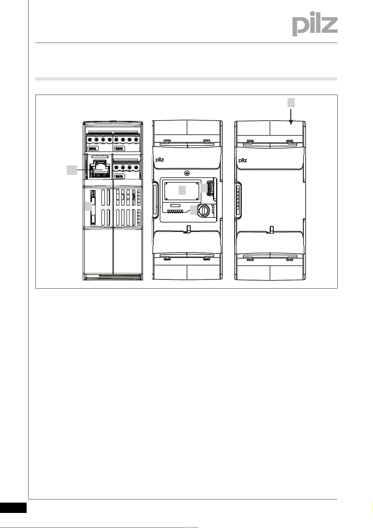
Fig. 2-1: Left: Side view, centre: Front view without cover, right:
Front view with cover
Legende
Legend:
A1, A2:
Supply connections
In1, In2, GND:
Proximity switch 1 - In1 (track A) and 2 - In2 (track B) and GND
Y10 ... Y13:
Select inputs (SEL1, SEL2, SEL4, SEL8)
13-14 and 23-24:
Relay outputs (safety contacts)
11-12 and 21-22:
Relay outputs (auxiliary contacts)
Y32 ... Y35: Semiconductor outputs (auxiliary outputs)
S11: +24 V / 30 mA (supply for S34, Y1 and Y2)
S21: 0 V (GND for S11, S34, Y1 and Y2)
S34: Reset input
Y30: 0 V ext (GND for select input and semiconductor outputs)
Y31: 24 V ext (supply for semiconductor outputs)
2-2
Pilz GmbH & Co. KG, Felix-Wankel-Straße 2, 73760 Ostfildern, Germany
Telephone: +49 711 3409-0, Telefax: +49 711 3409-133, E-Mail: pilz.gmbh@pilz.de
Page 13

2 Overview
2.2 Front/side view
Y1, Y2:
Y1: Feedback input for Rel. 1
Y2: Feedback input for Rel. 2:
X6: RJ45 socket for connecting the encoder
(tracks A, /A, B, /B, Z, /Z, S and GND). Proximity switches can be connected via RJ45 socket or connection terminals.
1: Chip card
2: Display
3: USB connection (service only)
4: Rotary knob
5: Expansion interface for 2 more external relay outputs
LEDs:
–Power
–In1
–In2
–Rel 1
–Rel 2
–Fault
Pilz GmbH & Co. KG, Felix-Wankel-Straße 2, 73760 Ostfildern, Germany
Telephone: +49 711 3409-0, Telefax: +49 711 3409-133, E-Mail: pilz.gmbh@pilz.de
2-3
Page 14

2 Overview
2-4
Pilz GmbH & Co. KG, Felix-Wankel-Straße 2, 73760 Ostfildern, Germany
Telephone: +49 711 3409-0, Telefax: +49 711 3409-133, E-Mail: pilz.gmbh@pilz.de
Page 15

3 Safety
3.1 Intended use
33000SafetySafety3-3.1Intended use3100Intended use3-Gertebeschreibung_Drehzahlwaechter_plus_Position_Bereich
S_DZW_Bestimmung/Gerteb eschreibung_Warnu ngen
The speed monitor monitors standstill, speed, speed range, position
and direction in accordance with EN ISO 13849-1 up to PL e and EN IEC
62061 up to SIL CL 3.
WARNING!
Users must take appropriate measures to detect or exclude
errors (e.g. slippage or broken shearpin) which cause the frequency of the encoder signal to no longer be proportional to the
monitored speed.
Appropriate measures are:
Using the monitored encoder to also control the drive
Mechanical solutions
Z-frequency monitoring with an additional proximity switch (Ini
pnp) on the same axis
Pilz GmbH & Co. KG, Felix-Wankel-Straße 2, 73760 Ostfildern, Germany
Telephone: +49 711 3409-0, Telefax: +49 711 3409-133, E-Mail: pilz.gmbh@pilz.de
3-1
Page 16

3 Safety
3.2 Safety regulations
3.2Safety regulations3200Safety regulations3-
3.2.1 Use of qualified personnel
Use of qualified personnel3-Sich Qualif. Personal
The products may only be assembled, installed, programmed, commissioned, operated, maintained and decommissioned by competent persons.
A competent person is someone who, because of their training, experience and current professional activity, has the specialist knowledge required to test, assess and operate the work equipment, devices,
systems, plant and machinery in accordance with the general standards
and guidelines for safety technology.
It is the company's responsibility only to employ personnel who:
Are familiar with the basic regulations concerning health and safety /
accident prevention
Have read and understood the safety guidelines given in this descrip-
tion
Have a good knowledge of the generic and specialist standards ap-
plicable to the specific application.
3.2.2 Warranty and liability
Warranty and liability3-Sich Gewhrleistung
3.2.3 Disposal
Disposal3-Si ch Entsorgung
All claims to warranty and liability will be rendered invalid if:
The product was used contrary to the purpose for which it is intended
Damage can be attributed to not having followed the guidelines in the
manual
Operating personnel are not suitably qualified
Any type of modification has been made (e.g. exchanging compo-
nents on the PCB boards, soldering work etc.).
In safety-related applications, please comply with the mission time t
M
in the safety-related characteristic data.
When decommissioning, please comply with local regulations regard-
ing the disposal of electronic devices (e.g. Electrical and Electronic
Equipment Act).
3-2
Pilz GmbH & Co. KG, Felix-Wankel-Straße 2, 73760 Ostfildern, Germany
Telephone: +49 711 3409-0, Telefax: +49 711 3409-133, E-Mail: pilz.gmbh@pilz.de
Page 17

3 Safety
3.2 Safety regulations
3.2.4 For your safety
For your safety3-Zu Ihrer Sicherheit_Drehzahlwaechter
The device is designed exclusively for use in an industrial environ-
ment. It is not suitable for use in a domestic environment, as this can
lead to interference.
The guarantee is rendered invalid if the housing is opened or unau-
thorised modifications are carried out.
Sufficient fuse protection must be provided on all output contacts
with capacitive and inductive loads.
Pilz GmbH & Co. KG, Felix-Wankel-Straße 2, 73760 Ostfildern, Germany
Telephone: +49 711 3409-0, Telefax: +49 711 3409-133, E-Mail: pilz.gmbh@pilz.de
3-3
Page 18

3 Safety
3-4
Pilz GmbH & Co. KG, Felix-Wankel-Straße 2, 73760 Ostfildern, Germany
Telephone: +49 711 3409-0, Telefax: +49 711 3409-133, E-Mail: pilz.gmbh@pilz.de
Page 19

4 Function description
4.1 Introduction
44000Function descriptionFunction description4-4.1Introduction4100Introduc tion4-Funktionen_Einführung
Proximity switches or rotary encoders record measured values, which
are evaluated in the speed monitor PNOZ s30. There are 9 monitoring
functions (F1 ... F9), which are performed simultaneously.
Up to 16 different parameter sets (P0 ... P15) for the monitoring functions
can be selected via the select inputs.
Configuration of the monitoring functions is menu-driven, using a rotary
knob. The outputs switch depending on the configuration.
An interface is available to connect a contact expansion module
Sicherheitseigenschaften_multi_allgemein
PNOZsigma, enabling the number of outputs to be expanded.
The relay conforms to the following safety criteria:
The circuit is redundant with built-in self-monitoring.
The safety function remains effective in the case of a component fail-
ure.
Pilz GmbH & Co. KG, Felix-Wankel-Straße 2, 73760 Ostfildern, Germany
Telephone: +49 711 3409-0, Telefax: +49 711 3409-133, E-Mail: pilz.gmbh@pilz.de
4-1
Page 20
4 Function description
A1 A2
Y10 Y11 Y12 Y13 Y30 Y31
Power
Reset/
Start
S34
=
~
Rel. 1
13
11
12
14
23
24
21
22
Feed-
back
Y32 Y33 Y34 Y35
Initiator
Input
In1 In2
GND
24 V
0 V
S11 S21
Inputs (SEL)
Select
Interface
Extended Relais
24 V ext
0 V ext
X6
RJ45
Y1 Y2
Rel. 2
Relay
Control
4.2 Block diagram
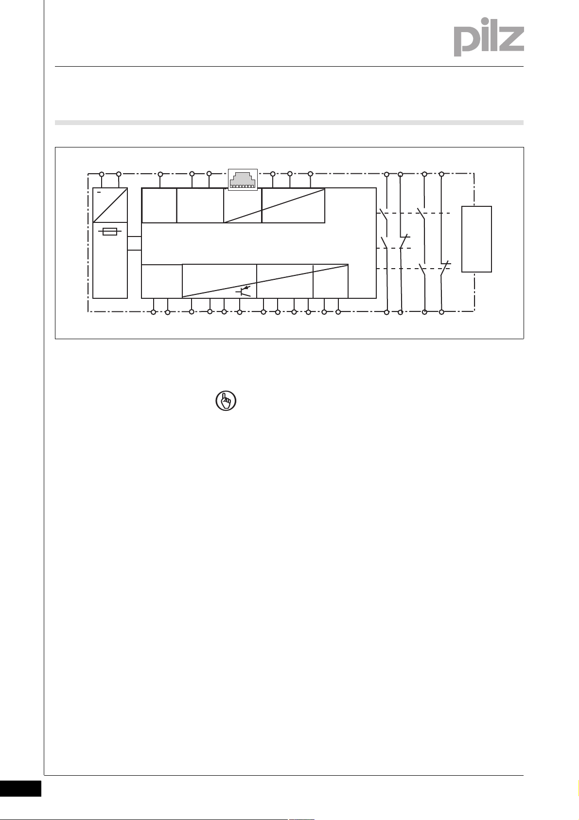
4.2Block diagram4200Block diag ram4-Blockschaltbild PNOZ s30
NOTICE
The individual blocks are galvanically isolated from each other:
Supply voltage: A1, A2
Encoder and initiator inputs: GND, In1, In2, RJ45 socket and
shield
Reset and feedback circuits: S21, S11, S34, Y1, Y2
Semiconductor outputs and select inputs: Y30, Y31, Y32, Y33,
Y34, Y35, Y10, Y11, Y12, Y13
Relay output 13, 14
Relay output 11, 12
Relay output 23, 24
Relay output 21, 22
If possible, the connections for the various earth potentials
(GND, S21, Y30 and A2) should not be connected, as noise susceptibility can be increased significantly as a result.
4-2
Pilz GmbH & Co. KG, Felix-Wankel-Straße 2, 73760 Ostfildern, Germany
Telephone: +49 711 3409-0, Telefax: +49 711 3409-133, E-Mail: pilz.gmbh@pilz.de
Page 21

4 Function description
Reference
Position
X
Window Width
Position
Window
4.3 Functions
4.3Functions4300Functions4-Funktionen_Überwachungsfunktionen
The following monitoring functions can be configured:
Standstill
With standstill monitoring, the output is switched on when the value falls
below the stated standstill value; if the standstill value is exceeded, the
output switches off.
Speed
With overspeed monitoring, the output switches off when the stated value is exceeded.
Speed range
With range monitoring, the output switches off if the rotational speed
(velocity, frequency) is outside the configured range.
Position
Position monitoring is activated via a rising edge at the reset input. The
current position is adopted as a reference position in the middle of the
position window (configured window width) and the assigned output is
switched on.
The output will stay switched on provided the value is within the position
window.
Pilz GmbH & Co. KG, Felix-Wankel-Straße 2, 73760 Ostfildern, Germany
Telephone: +49 711 3409-0, Telefax: +49 711 3409-133, E-Mail: pilz.gmbh@pilz.de
4-3
Page 22

4 Function description
4.3 Functions
If the value moves outside the configured range, position monitoring is
reset and the assigned outputs are switched off. Position monitoring can
be restarted via a rising edge at the reset input
A max. of 4 positions can be configured to be monitored simultaneously.
Please note:
Active position monitoring is not restarted by another rising edge at
the reset input.
Position monitoring cannot be used if proximity switches are em-
ployed.
Direction
If the direction is to be detected safely, this function must be linked to a
safety contact.
If "Direct. Right" is configured, the safety output is switched on during
normal operation in clockwise rotation.
If "Direct. Left" is configured, the safety output is switched on during
normal operation in anti-clockwise rotation.
For both directions, a tolerance can be entered for the wrong direction.
In other words, the drive can run in the wrong direction up to the set tolerance value, without the assigned output switching off.
If an output has been switched off, it cannot switch back on again until
the drive has been run in the right direction up to the tolerance value.
Please note: Direction cannot be detected if proximity switches are
used.
Monitoring for broken shearpins
An additional proximity switch can be connected to track Z to monitor
for broken shearpins
Hysteresis
For each switching function F1 ... F9 (with the exception of direction and
position), a hysteresis can be configured. This prevents the outputs on
the speed monitor from bouncing if there are fluctuations around the response value. The hysteresis becomes effective when the output is
switched on:
Switch-on value = switching threshold – hysteresis
For the lower range limit:
Switch-on value = switching threshold + hysteresis
4-4
Pilz GmbH & Co. KG, Felix-Wankel-Straße 2, 73760 Ostfildern, Germany
Telephone: +49 711 3409-0, Telefax: +49 711 3409-133, E-Mail: pilz.gmbh@pilz.de
Page 23

4 Function description
4.3 Functions
Reset modes
You can choose between the following reset modes:
Automatic reset
If an automatic reset is configured, the output switches on automatically if the speed does not reach the limit value, for example.
Monitored reset with rising edge
If a monitored reset with rising edge is configured, the output switches on if the speed does not reach the limit value and then a rising
edge is detected at S34.
Monitored reset with falling edge
If a monitored reset with falling edge is configured, the output switches on if the speed does not reach the limit value and then a falling
edge is detected at S34.
Switch delay
A delay time can be set for each output (see technical details). The outputs will not switch until the set time has elapsed. It is possible to configure whether the delay time is to be activated when switching on,
switching off, or switching on and off.
WARNING!
Potential loss of safety function due to increased reaction
time
The output switch-off delay (t
will increase the speed monitor's reaction time by the stated
value (see technical details). This must not delay the arrival of a
safe condition by more than the permitted time. The configuration of the switch-off delay must be considered in the risk
assessment as regards hazards, reaction time and safety distance.
, Off) when overspeed is reached
do
Pilz GmbH & Co. KG, Felix-Wankel-Straße 2, 73760 Ostfildern, Germany
Telephone: +49 711 3409-0, Telefax: +49 711 3409-133, E-Mail: pilz.gmbh@pilz.de
4-5
Page 24

4 Function description
4.3 Functions
Feedback loops
Feedback loops are used to monitor external contactors or relays. If a
relay output is activated, it will not switch on until the corresponding
feedback loop is closed.
Start-up delay
To avoid spurious output signals, during the machine's start-up phase,
evaluation of the encoder signals can be delayed after the supply voltage is switched on (see technical details).
Switching direction on semiconductor outputs
The semiconductor outputs can be operated in normally de-energised
or normally energised mode.
Units
The values to be configured can be entered in various units. Depending
on the axis type (linear or rotational axis), various units can be selected
for speed and distance (see chapter entitled "Menu overview").
4-6
Pilz GmbH & Co. KG, Felix-Wankel-Straße 2, 73760 Ostfildern, Germany
Telephone: +49 711 3409-0, Telefax: +49 711 3409-133, E-Mail: pilz.gmbh@pilz.de
Page 25

4 Function description
4.4 Speed configuration
4.4Speed configuration4400Speed configuration4-Funktionen_Drehzahlkonfiguration
The speed monitor is configured using the rotary knob on the device.
Up to 16 parameter sets (P0 ... P15), each with a max. of 9 switch functions (F1 ... F9) can be configured to monitor various operating modes,
for example.
One of the 16 parameter sets is selected via 4 select inputs SEL1 (Y10),
SEL2 (Y11), SEL4 (Y12), SEL8 (Y13).
The switch functions are monitored simultaneously.
Each of a switch function's 16 parameters can be configured as
Standstill limit
Speed limit
Upper or lower limit of speed range
Right-hand direction monitoring
Left-hand direction monitoring
Position monitoring 1 to 4 with width of position window 1 to 4
Exactly one switch function can be assigned to each output. The same
switch function can be assigned to several outputs. With range monitoring, a range is assigned to an output (F2-F3, F4-F5, F6-F7 or F8-F9).
A switch delay and reset mode can be configured for each output.
If only one parameter set is used, configure the parameter set P0. Then
it is not necessary to connect a select input.
INFORMATION
2 basic configurations are available for standard applications, for
simple configuration within the display menu. A basic configuration contains limited menu functions adapted for standard applications, with partly pre-defined parameters. Further information
about basic configurations can be found in this chapter, under
"Basic configuration".
Pilz GmbH & Co. KG, Felix-Wankel-Straße 2, 73760 Ostfildern, Germany
Telephone: +49 711 3409-0, Telefax: +49 711 3409-133, E-Mail: pilz.gmbh@pilz.de
4-7
Page 26
4 Function description
4.4 Speed configuration
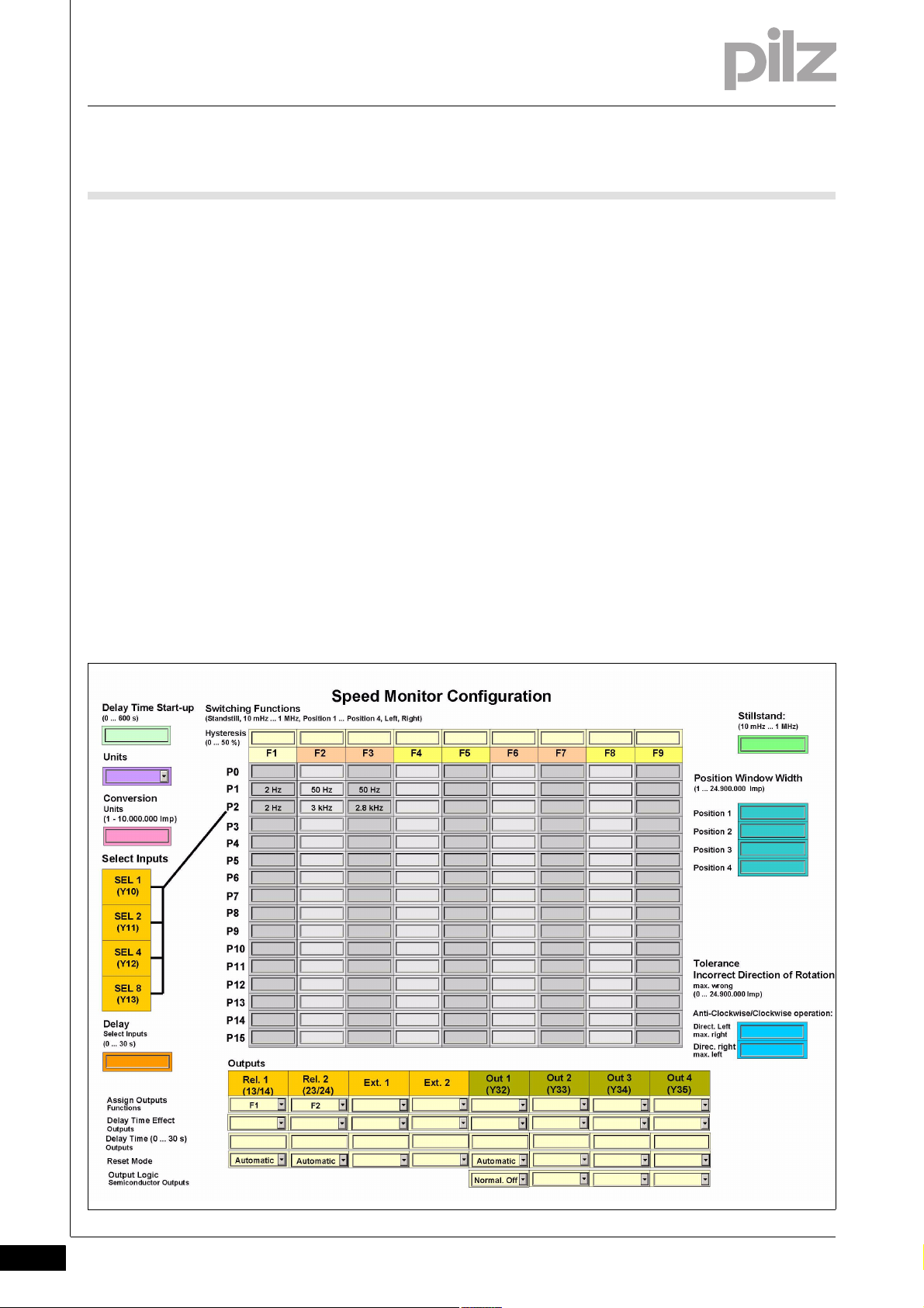
Example configuration:
2 parameter sets for 2 operating modes are configured:
Set-up: P1
Automatic mode: P2
The parameter set P2, "Automatic mode", is selected for speed monitoring (selection via the select inputs, see next chapter "Select inputs").
The following switch functions are selected for the parameter set P2:
F1: Standstill 2 Hz
F2: Overspeed: 3000 Hz
F3: Warning threshold: 2800 Hz
The following outputs are assigned to the switch functions:
F1: Relay output Rel. 1
F2: Relay output Rel. 2
F3: Semiconductor output Out 1
4-8
Pilz GmbH & Co. KG, Felix-Wankel-Straße 2, 73760 Ostfildern, Germany
Telephone: +49 711 3409-0, Telefax: +49 711 3409-133, E-Mail: pilz.gmbh@pilz.de
Page 27
4 Function description
4.4 Speed configuration
For documentation and a better overview of the device settings, we recommend that you fill in this configuration overview before setting the device parameters (link to form, see "Create configuration overview"
chapter).
4.4.1 Select Inputs
Select Inputs4-Funktionen_Select-Eingaenge
The parameter sets are selected via the 4 select inputs SEL1 (Y10), SEL2
(Y11), SEL4 (Y12), SEL8 (Y13). Only one of the configured parameter
sets can be selected.
For applications up to PL e of EN ISO 13849-1 and up to SIL CL 3 of
EN IEC 62061 max. 4 parameter sets can be configured: P1, P2, P4 and
P8 (or P0 if only 1 parameter set is used).
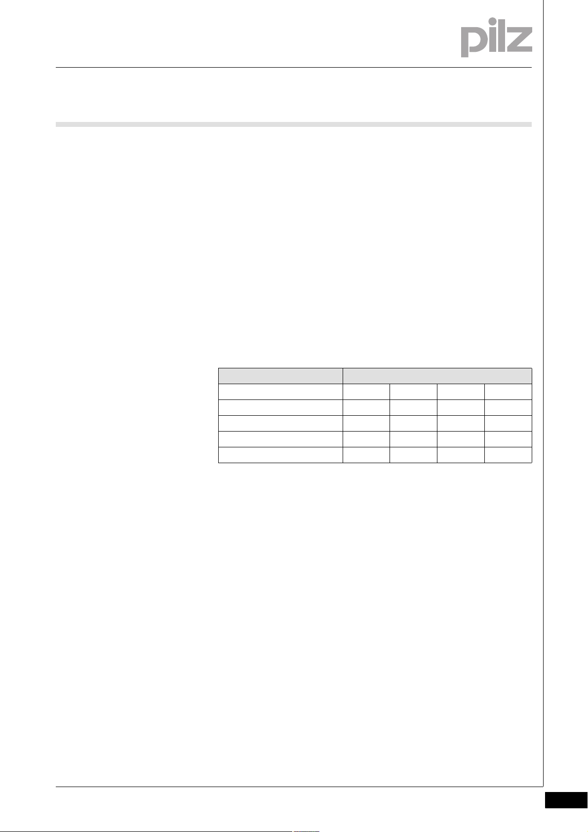
Parameter set Signal states of the select inputs
SEL 8 SEL 4 SEL 2 SEL 1
P1 0001
P2 0010
P4 0100
P8 1000
In all other parameter sets (P0, P3, P5 ... P7, P9 ... P15), the default value
"Standstill" must be configured for each switch function.
When using these 4 parameter sets, the following safety features are
met:
If there is an error when activating the select inputs, such as
Short circuits and shorts between contacts
Open circuit
Input drift
a parameter set other than P1, P2, P4 or P8 is selected. This means that
standstill is monitored.
If necessary, the number of parameter sets can be increased to max. 16.
These can only be used for applications up to max. PL d of
EN ISO 13849-1 and up to SIL CL 2 of EN IEC 62061.
Pilz GmbH & Co. KG, Felix-Wankel-Straße 2, 73760 Ostfildern, Germany
Telephone: +49 711 3409-0, Telefax: +49 711 3409-133, E-Mail: pilz.gmbh@pilz.de
4-9
Page 28

4 Function description
4.4 Speed configuration
Parameter set Signal states of the select inputs
P0 0000
P1 0001
P2 0010
P3 0011
P4 0100
P5 0101
P6 0110
P7 0111
P8 1000
P9 1001
P10 1010
P11 1011
P12 1100
P13 1101
P14 1110
P15 1111
SEL 8 SEL 4 SEL 2 SEL 1
When using the expanded parameter sets, please note:
If an open circuit occurs when the select inputs are activated, the system
will switch to a parameter set with a lower number (e.g. P7 -> P3 if an
open circuit occurs at SEL4).
The limit values for the switch functions should therefore be entered in
ascending order. (Parameter set P0 -> lowest values, parameter set P15
-> highest values).
Delay on the select inputs
A reaction time can be entered for the select inputs. That way it is possible to filter out invalid signals (e.g. contact bounce) that occur when
switching.
4-10
Pilz GmbH & Co. KG, Felix-Wankel-Straße 2, 73760 Ostfildern, Germany
Telephone: +49 711 3409-0, Telefax: +49 711 3409-133, E-Mail: pilz.gmbh@pilz.de
Page 29

4 Function description
4.4 Speed configuration
4.4.2 Switch functions
Switch functions4-_Dummy-Vorlage
Funktionen_Drehzahlkonfiguration_Stillstand
Funktionen_Drehzahlkonfiguration_Drehzahl
Funktionen_Drehzahlkonfiguration_Bereichsüberwachung
Funktionen_Drehzahlkonfiguration_Positionsüberwachung
Funktionen_Drehzahlkonfiguration_Drehrichtung
The following switch functions can be configured:
Standstill
The standstill frequency is configured centrally. The standstill frequency should be the lowest frequency in the configuration.
All switch function parameters are pre-configured to the default setting "Standstill" ex works.
Speed
Limit values can be configured to monitor for overspeed.
Limit values should be entered in ascending order (Parameter set P0
-> lowest values, parameter set P15 -> highest values)
Speed range
Up to 4 speed ranges can be monitored simultaneously.
Configure two switch functions to monitor a range:
–F2 and F3,
–F4 and F5,
–F6 and F7 or
–F8 and F9.
The switch function with the lower number (e.g. F2) operates as the
lower range limit; the switch function with the higher number (e.g. F3)
operates as the upper range limit.
Both switch functions can be assigned to one or more outputs.
Position
Up to 4 different position windows can be monitored: Position 1 ...
Position 4.
Each position to be monitored can be entered as often as necessary
in parameter sets P0 to P15 and switch functions F1 to F9.
Direction
The monitoring functions "Direct. Left" and "Direct. Right" can be
configured as a switch function as often as necessary.
For both directions, a tolerance can be entered for the wrong direc-
tion.
Pilz GmbH & Co. KG, Felix-Wankel-Straße 2, 73760 Ostfildern, Germany
Telephone: +49 711 3409-0, Telefax: +49 711 3409-133, E-Mail: pilz.gmbh@pilz.de
4-11
Page 30

4 Function description
4.4 Speed configuration
4.4.3 Basic configuration
Basic configuration4-Funktion en_Basiskonfiguration
Two basic configurations are available for standard applications, for
simple configuration within the display menu. A basic configuration contains limited menu functions adapted for standard applications, with
partly pre-defined parameters.
The following basic configurations are available:
Basic configuration 1: Ini pnp pnp (proximity switch)
Pre-defined settings and configuration options:
Encoder type
2 pnp type proximity switches
Switch functions
– Standstill (F1)
Standstill frequency configurable in Hz
–Speed (F2)
Max. frequency (v max) configurable in Hz
Parameter set/select input
P0, select inputs must be "0" (unconnected)
Hysteresis
Standstill and speed, 2 % each
Output assignment
– Standstill: Relay output Rel. 1 and semiconductor output Out 1
– Speed: Relay output Rel. 2 and semiconductor output Out 2
Reset mode
– Rel. 1, Rel. 2 Out 1, Out 2: Automatic reset
Switch delay
None
Max. encoder frequency
3.5 kHz
4-12
Basic configuration 2: Rotary encoder
Encoder type
Rotary encoder
Rotary encoder type configurable
Switch functions
– Standstill (F1)
Standstill frequency configurable in Hz
–Speed (F2)
Max. frequency (v max) configurable in Hz
–Direction (F3)
Direction left
Pilz GmbH & Co. KG, Felix-Wankel-Straße 2, 73760 Ostfildern, Germany
Telephone: +49 711 3409-0, Telefax: +49 711 3409-133, E-Mail: pilz.gmbh@pilz.de
Page 31

4 Function description
4.4 Speed configuration
Tolerance for wrong direction = 10 Imp
–Direction (F4)
Direction right
Tolerance for wrong direction = 10 Imp
Parameter set/select input
P0, select inputs must be "0" (unconnected)
Hysteresis
Standstill and speed, 2 % each
Output assignment
– Standstill: Relay output Rel. 1 and semiconductor output Out 1
– Speed: Relay output Rel. 2 and semiconductor output Out 2
– Direction left: External output Ext. 1 and semiconductor output Out
3
– Direction right: External output Ext. 2 and semiconductor output
Out 4
Reset mode
– All outputs: Automatic reset
Switch delay
None
Max. encoder frequency
1 MHz
4.4.4 Chip card
Chip card4-Funktionen_Chipkarte
For details of how to configure the basic configurations, see the chapter
entitled Commissioning/Display Menu - Configuration.
The set parameters, the name of the configuration and the passwords
are stored on the chip card (see section entitled "Using the chip card").
Pilz GmbH & Co. KG, Felix-Wankel-Straße 2, 73760 Ostfildern, Germany
Telephone: +49 711 3409-0, Telefax: +49 711 3409-133, E-Mail: pilz.gmbh@pilz.de
4-13
Page 32

4 Function description
Proximity switch 1
Proximity switch 2
4.5 Input device types
4.5Input device types4500Input device types4-
4.5.1 Proximity switch
Proximity switch4-S_DZW_Anford_Naeherungsschalter
The following proximity switches can be used:
–pnp
–npn
The proximity switches must be fitted so that at least one is always
activated. In other words, the proximity switches must be fitted such
that the recorded signals overlap.
The supply voltage of the proximity switches should be monitored via
track S.
CAUTION!
Appropriate installation measures should be taken to prevent a
foreign body coming between the signal encoder and the proximity switch. If not, the foreign body could cause invalid signals.
Please note the values stated in the technical details
The maximum frequency of the used encoders must be entered for a
complete configuration ("Encoder" Menu -> "Track AB" -> "Track AB
fmax" / "Track Z" -> "Track Z fmax").
4-14
Pilz GmbH & Co. KG, Felix-Wankel-Straße 2, 73760 Ostfildern, Germany
Telephone: +49 711 3409-0, Telefax: +49 711 3409-133, E-Mail: pilz.gmbh@pilz.de
Page 33

4 Function description
4.5 Input device types
4.5.2 Rotary encoders
Rotary encoders4-S_DZW_Anford_Drehgeber
The following rotary encoders can be used:
– TTL, HTL (single-ended or differential signals)
– sin/cos 1 Vss
– Hiperface
The rotary encoders can be connected with or without Z index (0 in-
dex)
A proximity switch can also be connected to track Z for monitoring
broken shearpins
Track S can be used:
– To connect an encoder's error output
– To monitor voltages between 0 V and 30 V for a permitted upper
and lower limit. For example, the encoder's supply voltage can be
monitored.
The maximum frequency of the used encoders must be entered for a
complete configuration ("Encoder" Menu -> "Track AB" -> "Track AB
fmax" / "Track Z" -> "Track Z fmax").
Please note the values stated in the technical details
4.5.2.1 Adapter for incremental encoders
Adapter for incremental encoders4-Drehzahlwaechter_Inkrementalgeber_Adapter
The adapter records the data between the incremental encoder and the
drive and makes it available to the speed monitor via the RJ45 socket.
Pilz supplies complete adapters as well as ready-made cable with RJ45
connector, which can be used when making your own adapter. The
range of products in this area is constantly being expanded. Please contact us about the range of adapters that is currently available.
Pilz GmbH & Co. KG, Felix-Wankel-Straße 2, 73760 Ostfildern, Germany
Telephone: +49 711 3409-0, Telefax: +49 711 3409-133, E-Mail: pilz.gmbh@pilz.de
4-15
Page 34

4 Function description
4-16
Pilz GmbH & Co. KG, Felix-Wankel-Straße 2, 73760 Ostfildern, Germany
Telephone: +49 711 3409-0, Telefax: +49 711 3409-133, E-Mail: pilz.gmbh@pilz.de
Page 35

5 Installation
5.1 General installation guidelines
55000InstallationInstallation5-5.1General installation guidelines5100General installation guidelines5-][Montage_Drehzahlwächter
Install base unit without contact expander module:
Ensure that the plug terminator is inserted at the side of the unit.
Connect base unit and PNOZsigma contact expander module:
Remove the plug terminator at the side of the base unit and at the
contact expander module.
Connect the base unit and the contact expander module to the sup-
plied connector before mounting the units to the DIN rail.
Control cabinet installation
The unit should be installed in a control cabinet with a protection type
of at least IP54.
It is preferable to install the device on a horizontal DIN rail in order to
ensure the best possible convection.
Use the locking element on the rear of the device to attach it to the
DIN rail.
Push the device upwards or downwards before lifting it from the DIN
Montage_EMV ESD
rail.
CAUTION!
Damage due to electrostatic discharge!
Electrostatic discharge can damage components. Ensure
against discharge before touching the product, e.g. by touching
an earthed, conductive surface or by wearing an earthed armband.
Pilz GmbH & Co. KG, Felix-Wankel-Straße 2, 73760 Ostfildern, Germany
Telephone: +49 711 3409-0, Telefax: +49 711 3409-133, E-Mail: pilz.gmbh@pilz.de
5-1
Page 36

5 Installation
120 (4.72")
* 100 (3,94")
98 (3.86")
45
(1.77")
5.1 General installation guidelines
5.1.1 Dimensions
Dimensions5-Abmessungen
*with spring-loaded terminals
5-2
Pilz GmbH & Co. KG, Felix-Wankel-Straße 2, 73760 Ostfildern, Germany
Telephone: +49 711 3409-0, Telefax: +49 711 3409-133, E-Mail: pilz.gmbh@pilz.de
Page 37

6 Commissioning
8 1
A1
L1
N
A2
A1
L+
A2
L-
6.1 Wiring
66000CommissioningCommissioning6-6.1Wiring6100Wiring6-
6.1.1 General wiring guidelines
General wiring guidelines6-Verdrahtung_Kupferdra ht_75C
Note:
Information given in the "Technical details" must be followed.
Verdrahtung
6.1.2 Pin assignment of RJ45 socket
Pin assignment of RJ45 socket6-Anschlussbelegung RJ45-Buchse
Use copper wire that can withstand 75 °C.
The cable used to connect the rotary encoder and proximity switch
must be shielded (see connection diagrams in this chapter).
If possible, the connections for the various earth potentials (GND,
S21, Y30 and A2) should not be connected, as noise susceptibility
can be increased significantly as a result.
RJ45 socket
8-pin
6.1.3 Supply voltage
Supply voltage6-Anschluss_Versorgungsspannung
Supply voltage AC DC
PIN Track
1S
2GND
3Z
4A
5/A
6/Z
7B
8/B
Pilz GmbH & Co. KG, Felix-Wankel-Straße 2, 73760 Ostfildern, Germany
Telephone: +49 711 3409-0, Telefax: +49 711 3409-133, E-Mail: pilz.gmbh@pilz.de
6-1
Page 38

6 Commissioning
IN2
IN1
GND
24 V
0 V
INI_A
INI_B
RJ45
A
/A
B
/B
Z
/Z
GND
S
6.1 Wiring
6.1.4 Connection of proximity switches
Connection of proximity switches6-S_DZW_Betriebsb_Anschluss_Naeherungssch
The following proximity switch combinations can be connected:
A: pnp, B: pnp
A: npn, B: npn
A: pnp, B: npn
A: npn, B: pnp
When connecting proximity switches please note:
Proximity switches can either be connected to terminals In1, In2 and
GND or to tracks A and B plus GND on the RJ45 socket.
Track S should be used to monitor the supply voltage (see drawing).
A permitted voltage range can be entered in the menu.
Connect the proximity switch to 24 VDC of the power supply.
6-2
Pilz GmbH & Co. KG, Felix-Wankel-Straße 2, 73760 Ostfildern, Germany
Telephone: +49 711 3409-0, Telefax: +49 711 3409-133, E-Mail: pilz.gmbh@pilz.de
Page 39

6 Commissioning
X6
PNOZ s30
2
4
7
A
B
GND
Input Device
X6
PNOZ s30
2
4
5
7
8
A
/A
B
/B
GND
Input Device
6.1 Wiring
6.1.5 Connection of a rotary encoder
Connection of a rotary encoder6-S_DZW_Betriebsb_Inkremen
Proceed as follows when connecting the rotary encoder:
The rotary encoder be connected via an adapter (e.g. PNOZ msi6p) or
can be connected directly to the speed monitor.
Use only shielded cables for all connections
Always connect GND on the rotary encoder to GND on the RJ45 con-
nector.
6.1.5.1 Connect rotary encoder to speed monitor
Connect rotary encoder to speed monitor6-S_DZW_Betriebsb_Anschluss_Inkrementalgeber
Encoder types:
TTL single ended
HTL single ended
Please note:
Tracks /A and /B must remain free
Encoder types:
TTL differential
HTL differential
sin/cos 1 Vss
Hiperface
Pilz GmbH & Co. KG, Felix-Wankel-Straße 2, 73760 Ostfildern, Germany
Telephone: +49 711 3409-0, Telefax: +49 711 3409-133, E-Mail: pilz.gmbh@pilz.de
6-3
Page 40

6 Commissioning
X6
PNOZ s30
2
4
7
A
B
GND
Input Device
3
Z
X6
PNOZ s30
2
4
5
7
8
A
/A
B
/B
GND
Input Device
3
Z
/Z
6
6.1 Wiring
6.1.5.2 Connect rotary encoder with Z index to speed monitor
Connect rotary encoder with Z index to speed monitor6-S_DZW_Betriebsb_Anschluss_Inkrementalgeber_Z-Index
Encoder types:
TTL single Z Index
HTL single Z Index
Please note:
Tracks /A, /B and /Z must remain free
Encoder types:
TTL diff. Z Index
HTL diff. Z Index
sin/cos 1 Vss Z Index
6-4
Pilz GmbH & Co. KG, Felix-Wankel-Straße 2, 73760 Ostfildern, Germany
Telephone: +49 711 3409-0, Telefax: +49 711 3409-133, E-Mail: pilz.gmbh@pilz.de
Page 41

6 Commissioning
Input Device
A
/A
B
/B
X6
PNOZ s30
Drive
Adapter
GND
GND
18
24 V
0 V
X6
PNOZ s30
2
4
7
A
B
GND
Input Device
3
1
6.1 Wiring
6.1.5.3 Connect rotary encoder to the speed monitor via an adapter
Connect rotary encoder to the speed monitor via an adapter6-S_DZW_Betriebsb_Anschluss_IInkremen_ueber_Adapt
The adapter (e.g. PNOZ msi6p) is connected between the rotary encoder and the drive. The output on the adapter is connected to the RJ45
socket on the speed monitor.
6.1.6 Connection of proximity switch and rotary encoder
Connection of proximity switch and rotary encoder6-S_DZW_Betriebsb_Anschluss_Inkrement_Naeherungssch
Encoder types:
TTL single Z Freq. Ini pnp
HTL single Z Freq. Ini pnp
Please note:
Tracks /A, /B and /Z must remain free.
Pilz GmbH & Co. KG, Felix-Wankel-Straße 2, 73760 Ostfildern, Germany
Telephone: +49 711 3409-0, Telefax: +49 711 3409-133, E-Mail: pilz.gmbh@pilz.de
6-5
Page 42

6 Commissioning
24 V
0 V
X6
PNOZ s30
2
4
5
7
8
A
/A
B
/B
GND
Input Device
3
1
S11
S34
S3
Y1
Y2
S11
K5
K6
K5
L+
L-
K6
Y1
13 (23)
Y2
14
S11
24
S21
6.1 Wiring
Encoder types:
TTL differential Z Freq. Ini pnp
HTL differential Z Freq. Ini pnp
sin/cos 1 Vss Z Freq. Ini pnp
Hiperface Z Freq. Ini pnp
Please note:
Track /Z must remain free!!
6-6
6.1.7 Reset circuit
Reset circuit6-Anschluss_Startkreis
Automatic reset Monitored reset
Automatic reset must only be configured
No wiring necessary!
6.1.8 Feedback circuit
Feedback circuit6-Rueckfuehrkreis
Link Contacts from external contactors
Pilz GmbH & Co. KG, Felix-Wankel-Straße 2, 73760 Ostfildern, Germany
Telephone: +49 711 3409-0, Telefax: +49 711 3409-133, E-Mail: pilz.gmbh@pilz.de
Page 43

6 Commissioning
Y10 (Y11, Y12, Y13)
PLC Output
Y30
PLC 0 V
Y31
PLC +24 V
Y30
PLC 0 V
Y32 (Y33, Y34, Y35)
PLC Input
6.1 Wiring
6.1.9 Select inputs
Select inputs6-Anschluss_Eingangskreis
6.1.10 Semiconductor outputs
Semiconductor outputs6-Anschluss_Halbleiterausgang
Pilz GmbH & Co. KG, Felix-Wankel-Straße 2, 73760 Ostfildern, Germany
Telephone: +49 711 3409-0, Telefax: +49 711 3409-133, E-Mail: pilz.gmbh@pilz.de
6-7
Page 44

6 Commissioning
6.2 Display menu - Configuration
6.2Display menu - Configuration6200Display menu - Configuration6-Inbetriebnahme_Drehknopf_Funktion
The menu settings are made on the unit's display via a rotary knob. You
have the option to make the settings on the knob by hand or with a
screwdriver. If you make the settings with a screwdriver, the knob can
remain within the unit.
6.2.1 Create configuration overview
Create configuration overview6-S_DZW_Inbetriebnahme_Konfigurat ionsübersicht_erstellen
For a better overview, before entering the configuration values we recommend that they are entered in the attached form
PNOZ_s30_Config_Overview
:
6-8
Pilz GmbH & Co. KG, Felix-Wankel-Straße 2, 73760 Ostfildern, Germany
Telephone: +49 711 3409-0, Telefax: +49 711 3409-133, E-Mail: pilz.gmbh@pilz.de
Page 45

6 Commissioning
A
1.
2.
B
6.2 Display menu - Configuration
6.2.2 Operate rotary knob
Operate rotary knob6-Inbetriebnahme_Drehknopf_Bild
Inbetriebnahme_Drehknopf_Funktion_heraus_und_zurck
The rotary knob:
(A) should be pulled out until it clicks into position
(B) then released and retracted back into the unit:
– Press the latch on the side of the rotary knob (1) towards the centre
of the knob. This releases the rotary knob.
– Press the knob downwards (2) while keeping the latch held down.
6.2.3 Configure Speed Monitor
Configure Speed Monitor6-Inbetriebnahme_Drehknopf_Funktion_drcken_drehen_anzeigen
The settings are made via the rotary knob, as follows:
Press the knob
Confirm selection/setting
Switch to menu
Rotate knob
Inbetriebnahme_Drehknopf_Funktion_drcken_drehen_konfigurieren
Inbetriebnahme_Drehknopf_Funktion_drehen_schnell_Menü-Deutsch
Select menu level
Set the parameter/numeric value
The speed with which you turn the knob affects the sequence of the
menu and numeric values:
Slowly: Units
Quickly: Tens
Very quickly:
– Setting the numeric value: Hundreds
– When switching the menu level: Jump to CANCEL
Inbetriebnahme_Display_W ichtig_Eingabepfli cht_s30
NOTICE
Please note that all parameters are set to their default values on
delivery.
Please check all the safety-related parameters at least, and
enter the values that correspond to your application.
Inbetriebnahme_Display_Info_Standardanzeige_30s_5min
Pilz GmbH & Co. KG, Felix-Wankel-Straße 2, 73760 Ostfildern, Germany
Telephone: +49 711 3409-0, Telefax: +49 711 3409-133, E-Mail: pilz.gmbh@pilz.de
6-9
Page 46

6 Commissioning
6.2 Display menu - Configuration
INFORMATION
If no value is set or amended within 30 s of a menu action, the
display reverts to the default display. The current setting remains
unchanged.
If the master password has been entered, this time increases to
5 minutes.
6.2.4 Password protection
Password protection6-Kennwortschutz
The configuration is protected through passwords. There is a master
password and a customer password.
Factory setting for both passwords: 0000
The password levels contain different authorisations:
Master password
Display: All settings
Edit: All settings
Customer password
Display: All settings
Edit:
– The customer password can be changed.
– The language can be changed.
– The settings can be reset to the factory settings.
No password
Edit:
– The language can be changed.
– The settings can be reset to the factory settings.
If the settings are reset to the factory settings, the passwords and the
language will also be reset to the factory settings.
The passwords can be changed at any time in the menu.
Enter a password containing 4 characters.
6-10
Pilz GmbH & Co. KG, Felix-Wankel-Straße 2, 73760 Ostfildern, Germany
Telephone: +49 711 3409-0, Telefax: +49 711 3409-133, E-Mail: pilz.gmbh@pilz.de
Page 47

6 Commissioning
6.2 Display menu - Configuration
6.2.5 Use chip card
Use chip card 6-Inbetriebnahme_Chipkarte_verwenden_Konfiguration_deutsch
The parameters that are set on a unit can be stored on the chip card. The
data is stored along with a device identifier, the passwords, the name of
the configuration and the check sum. We recommend that you always
operate the unit with a chip card.
If the parameters on a device have been changed due to an error, they
can be restored using the backup copy on the chip card.
If a unit requires maintenance or needs to be exchanged, the chip
card can be used to download the parameters to another unit.
INFORMATION
If you operate the unit without a chip card, the "Fault" LED will
light and the following message will appear once only: Please
Insert SIM Card!. If you change the parameters, the Please
Insert SIM Card! message will reappear.
The message disappears after 30 s or by pressing the rotary
knob.
When the chip card is inside the unit:
The chip card is checked to verify the device identifier, valid parame-
ters, and ensure that the data is identical.
Unit parameters are automatically saved to the chip card during op-
eration. As a result, the chip card always contains a copy of the unit's
current internal data. Exception: If you select Write configuration to
SIM: No.
Pilz GmbH & Co. KG, Felix-Wankel-Straße 2, 73760 Ostfildern, Germany
Telephone: +49 711 3409-0, Telefax: +49 711 3409-133, E-Mail: pilz.gmbh@pilz.de
6-11
Page 48

6 Commissioning
6.2 Display menu - Configuration
6.2.5.1 Insert chip card
Insert chip card 6-Inbetriebnahme_Chipkarte_einsetzen_1_wichtig_Kontaktflaeche_sauber
NOTICE
The chip card contact is only guaranteed if the contact surface is
clean and undamaged. For this reason please protect the chip
card's contact surface from
Contamination
Contact
Mechanical impact, such as scratches.
Inbetriebnahme_Chipkarte_einsetzen_3_Chipkarte_nicht verkantet
Make sure that you do not bend the chip card as you insert it into the
Inbetriebnahme_Chipkarte_einsetzen_4_Chipkarte_nicht verkantet_Bild_sigma
chip card slot.
6.2.5.2 Write data to chip card
Write data to chip card 6-Inbetriebnahme_Daten_auf_Chipkarte_schreiben_Text
If you are inserting a chip card which has not yet been written by a PNOZ
s30, you have the option to:
Inbetriebnahme_Daten_auf_Chipkarte_schreiben_zulassen_deutsch
Allow data to be written to the chip card
Insert chip
card
Please insert SIM
Card!
Write configuration to
SIM: No?
Inbetriebnahme_Daten_auf_Chipkarte_schreiben_nicht-zulassen_deutsch
Do not allow data to be written to the chip card
Insert chip card 1. Data is not written to the chip card
Please insert SIM Card! Write configura-
tion to SIM: No?
1. 2. Data is written to the chip
Write configuration to SIM:
Yes?
Insert rewritable SIM Card!
card
Current menu
6-12
Pilz GmbH & Co. KG, Felix-Wankel-Straße 2, 73760 Ostfildern, Germany
Telephone: +49 711 3409-0, Telefax: +49 711 3409-133, E-Mail: pilz.gmbh@pilz.de
Page 49

6 Commissioning
6.2 Display menu - Configuration
6.2.5.3 Read data from chip card
Read data from chip card6-Inbetriebnahme_Daten_von_Chipkarte_lesen_Text-1
If you are inserting a chip card which has not yet been written by a PNOZ
s30, you have the option to:
Inbetriebnahme_Daten_von_Chipkarte_lesen_zulassen_deutsch
Allow data to be read from the chip card
Insert chip card (data on chip
card different from device)
Current
menu
SIM: Name of the configuration (8 characters)
CRC: 12345 (0 .. 65535)
Load SIM: No?
Inbetriebnahme_Daten_von_Chipkarte_lesen_nicht-zulassen_deutsch
Do not allow data to be read from the chip card
Insert chip card (Data on chip
card different from device)
Current menu SIM: Name of the configurati-
on (8 characters)
CRC: 12345 (0 .. 65535)
Load SIM: No?
1. 2. Data is read into the de-
vice
SIM: Name of
Current menu
the configuration (8 characters)
CRC: 12345 (0
.. 65535)
Load SIM:
Yes?
1. Data is not read into the device, data is written to
the chip card
Write configuration to SIM: No?
(for more details see "Write data to chip card)
6.2.5.4 Transfer device parameters
Transfer device parameters 6-Inbetriebnahme_Gerteparam eter_bertragen_deutsch
You can transfer device parameters from one device to another using
the chip card.
Proceed as follows:
Remove chip card containg the data from device 1.
Insert chip card in device 2.
Confirm the message Load SIM Yes?.
The data is transferred.
Pilz GmbH & Co. KG, Felix-Wankel-Straße 2, 73760 Ostfildern, Germany
Telephone: +49 711 3409-0, Telefax: +49 711 3409-133, E-Mail: pilz.gmbh@pilz.de
6-13
Page 50

6 Commissioning
6.2 Display menu - Configuration
6.2.5.5 Duplicate chip card
Duplicate chip card6-_Dummy-Vorlage
You can also create copies of a chip card and its data.
Proceed as follows:
Remove chip card containg the device data.
Insert a new chip card into the device.
Confirm the message Write configuration to SIM Yes?.
The new chip card is written.
6.2.6 Menu overview
Menu overview6-Menue-Einstellungen-einf ührung
6.2.6.1 Permanent display
Permanent display6-Menu e-Einstellungen-D aueranzeige
The tables provide an overview of the menu settings.
The attached Excel file provides a detailed view of the setting options:
PNOZ_s30_Menu_Overview
.
If no settings are made, information regarding the configuration and current values are shown on the display.
You can change the permanent display on the display in the "Settings"
menu.
6-14
Pilz GmbH & Co. KG, Felix-Wankel-Straße 2, 73760 Ostfildern, Germany
Telephone: +49 711 3409-0, Telefax: +49 711 3409-133, E-Mail: pilz.gmbh@pilz.de
Page 51

6 Commissioning
6.2 Display menu - Configuration
6.2.6.2 Basic settings Ini pnp pnp
Basic settings Ini pnp pnp6-Menue-Einstellungen-Basiskonfiguration1
Settings for basic configuration 1
Level Designation
on the display
1 Basic Param.
Ini pnp pnp
Default:
Load?
2 Standstill
Rel.1 Out 1
Default:
2.00 Hz
2 v max:
Rel.1 Out 2
Default:
500 Hz
Description Settings
Select the default settings with which
the basic configuration menu "Ini pnp
pnp" is to be called:
-Load: The basic parameters are
loaded. Switches afterwards to the
basic menu "Ini pnp pnp".
The basic parameters should always
be loaded when commissioning for
the first time.
-Change: The basic parameters are
not loaded, i.e. all parameters are retained. The basic menu parameters
can be changed within the permitted
boundaries.
-CANCEL: Exits the basic menu.
Enter standstill frequency 100 mHz ... 10.0 Hz
Enter the max. permitted speed 10 mHz ... 3.00 kHz
Other, pre-defined settings:
Encoder type
2 pnp type proximity switches
Parameter set/select input
P0, select inputs must be "0" (unconnected)
Hysteresis
Standstill and speed, 2 % each
Output assignment
– Standstill: Relay output Rel. 1 and semiconductor output Out 1
– Speed: Relay output Rel. 2 and semiconductor output Out 2
Reset mode
– Rel. 1, Rel. 2 Out 1, Out 2: Automatic reset
Switch delay
None
Max. encoder frequency
3.5 kHz
Pilz GmbH & Co. KG, Felix-Wankel-Straße 2, 73760 Ostfildern, Germany
Telephone: +49 711 3409-0, Telefax: +49 711 3409-133, E-Mail: pilz.gmbh@pilz.de
6-15
Page 52

6 Commissioning
6.2 Display menu - Configuration
6.2.6.3 Basic settings for the rotary encoder
Basic settings for the rotary encoder6-Menue-Einstellungen-Basiskonfiguration2
Settings for basic configuration 2
Level Designation
on the display
1 Basic Param.
Encoder:
Default:
Load?
2 InputDevice
Default:
TTL
Differential
2 Standstill
Rel.1 Out 1
Default:
100 Hz
2 v max:
Rel.2 Out 2
Default:
5.00 kHz
Description Settings
Select the default settings with which
the basic configuration menu "Rotary
encoder" is to be called:
-Load: The basic parameters are
loaded. Switches afterwards to the
basic menu "Rotary encoder".
The basic parameters should always
be loaded when commissioning for
the first time.
-Change: The basic parameters are
not loaded, i.e. all parameters are retained. The basic menu parameters
can be changed within the permitted
boundaries.
-CANCEL: Exits the basic menu.
Select rotary encoder type -TTL differential (A, /A, B, /B)
-TTL single ended
-HTL differential (A, /A, B, /B)
-HTL single ended
-sin/cos 1 Vss (A, /A, B, /B)
-Hiperface (A, /A, B, /B)
Enter standstill frequency 10 mHz to 1.00 kHz
Enter the max. permitted speed 10 mHz to 1.00 MHz
6-16
Other, pre-defined settings:
Switch functions
–Direction (F3)
Direction left
Tolerance for wrong direction = 10 Imp
–Direction (F4)
Direction right
Tolerance for wrong direction = 10 Imp
Parameter set/select input
P0, select inputs must be "0" (unconnected)
Hysteresis
Standstill and speed, 2 % each
Pilz GmbH & Co. KG, Felix-Wankel-Straße 2, 73760 Ostfildern, Germany
Telephone: +49 711 3409-0, Telefax: +49 711 3409-133, E-Mail: pilz.gmbh@pilz.de
Page 53

6 Commissioning
6.2 Display menu - Configuration
Output assignment
– Standstill: Relay output Rel. 1 and semiconductor output Out 1
– Speed: Relay output Rel. 2 and semiconductor output Out 2
– Direction left: External output Ext. 1 and semiconductor output Out
3
– Direction right: External output Ext. 2 and semiconductor output
Out 4
Reset mode
– All outputs: Automatic reset
Switch delay
None
Max. encoder frequency
1 MHz
6.2.6.4 Settings
Settings6-Menue-Einstellungen-Eins tellungen
Level Designation
on the display
1 Permanent display
Default:
H : Min : Sec (system
time)
V (current speed of
track AB)
Position
1 Display Unit
Speed: Dist:
Default:
Hz - Imp
1 Conversion
Default:
1Hz =
1 Imp / s
Description Settings
Permanent display
Current values and information regarding configuration are displayed.
You can change the permanent display on the display
Select unit of speed and distance (position)
wählen.
Unit conversion.
Enter ratio of unit to pulses.
Display combinations:
- vz (current speed of track Z)
- v (current speed of track AB)
- Position
- Switch functions F1 ... F9
- v (current speed of track AB)
- Position
- Line 1/2: F1/F2, F3/F2, F5/F4, F7/F6 or F9/
F8
(parameters selected via select inputs).
v (current speed of track AB)
- H : Min : Sec (system time:)
- v (current speed of track AB)
- Position
Speed (rotional speed) - Dist. (distance/po-
sition)
Hz - Imp (pulse)
Hz - Edg (edge)
m/s - m
m/min - m
m/h - m
rps - rev
rpm - rev
Display
1 Hz = 1 Imp/s
1 Hz = 4 Edg/s
1m = x Imp (x = 1 ... 10.000.000 Imp)
1 rev = x Imp (x = 1 ... 10.000.000 Imp)
Pilz GmbH & Co. KG, Felix-Wankel-Straße 2, 73760 Ostfildern, Germany
Telephone: +49 711 3409-0, Telefax: +49 711 3409-133, E-Mail: pilz.gmbh@pilz.de
6-17
Page 54

6 Commissioning
6.2 Display menu - Configuration
Level Designation
on the display
1InputDevice
Settings
2 InputDevice
Default:
Undefined
Description Settings
Create encoder configuration for the
tracks A,
/A, B, /B, Z, /Z, S
Select pre-defined encoder types for
the tracks A, B and Z:
Proximity switch
Rotary encoder
- with and without inverted signals
- with or without Z index (0 index)
- with proximity switch at track Z
Note:
If "Undefined" is selected, an error
message is shown when you confirm
the menu
No encoder selected:
- Undefined
Proximity switch (Ini):
- Initiator A: pnp B: pnp
- Initiator A: npn B: npn
- Initiator A: pnp B: npn
- Initiator A: npn B: pnp
Rotary encoder:
TTL
- TTL differential (A, /A, B, /B)
- TTL single ended (A, B)
TTL with Z index
- TTL diff. Z index (A, /A, B, /B, Z, /Z)
- TTL single Z index (A, B, Z)
HTL
- HTL differential (A, /A, B, /B)
- HTL single ended (A, B)
HTL with Z index
- HTL diff. Z Index (A, /A, B, /B, Z, /Z)
- HTL single Z Index (A, B, Z)
Sin/Cos 1 Vss
- sin/cos 1 Vss (A, /A, B, /B)
Sin/Cos 1 Vss with Z index
- sin/cos 1 Vss Z Index (A, /A, B, /B, Z, /Z)
Hiperface
- Hiperface (A, /A, B, /B)
6-18
Rotary encoder + pnp proximity switch
TTL + pnp proximity switch
- TTL diff. (A, /A, B, /B), Z Freq Inipnp (Z)
- TTL single (A, B), Z Freq Inipnp (Z)
HTL + pnp proximity switch
- HTL diff. (A, /A, B, /B), Z Freq Inipnp (Z)
- HTL single (A, B), Z Freq Ini pnp (Z)
sin/cos 1 Vss + pnp proximity switch
- sin /cos 1 Vss (A, /A, B, /B), Z Freq Inipnp
(Z)
Hiperface + pnp proximity switch
- Hiperface (A, /A, B, /B), Z Freq Inipnp (Z)
2 Track AB Settings for tracks A and B
3 Type AB For information only:
Information on configured encoder
type on tracks A and B
Pilz GmbH & Co. KG, Felix-Wankel-Straße 2, 73760 Ostfildern, Germany
Telephone: +49 711 3409-0, Telefax: +49 711 3409-133, E-Mail: pilz.gmbh@pilz.de
Page 55

6 Commissioning
6.2 Display menu - Configuration
Level Designation
on the display
3 Track /A/B For information only:
3 AB Direction
Default:
Normal
3 Track AB fmax
Default:
10 mHz
2 Track Z Settings for track Z
3 Type Z For information only:
3 Track /Z For information only:
3 Track Z fmax
Default:
10 mHz
Description Settings
Information on the use of the inverted
tracks /A and /B:
No track /A /B
or
Inverted (inverted tracks /A and /B
used)
or
external (e.g. "Hiperface" encoder
U
ref
type)
Select direction for tracks A and B In-
formation:
This function is used to display a forward movement as positive linear/rotational speed, irrespective of the
installation of the rotary encoder.
Enter max. frequency of the encoder
on tracks A and B
Important:
The frequency must be less than or
equal to the max. encoder frequency
specified in the encoder's data sheet
and less than the max. speed of the
monitored drive.
Information on configured encoder
type at track Z
Information on the use of the inverted
track /Z:
No track /Z
or
Inverted (inverted track /Z used)
Enter max. frequency of the encoder
on track Z
Important:
The frequency must be less than the
max. encoder frequency specified in
the encoder's data sheet
- Normal
- Inverted
10 mHz … 1.00 MHz
10 mHz … 1.00 MHz
Pilz GmbH & Co. KG, Felix-Wankel-Straße 2, 73760 Ostfildern, Germany
Telephone: +49 711 3409-0, Telefax: +49 711 3409-133, E-Mail: pilz.gmbh@pilz.de
6-19
Page 56

6 Commissioning
6.2 Display menu - Configuration
Level Designation
on the display
fAB/fZ Verh.
Default:
1,0000 : 1
2 Track S Settings for track S (error track)
3 Track S
Default:
Not used
3 Track S Umax
Default:
6.0 V
3 Track S Umin
Default:
2.0 V
1 Delay Time
Start-up
Default:
0.00 s
1 Function
Parameter
2 Standstill
v max:
Default:
2.00 Hz
2 (F1 … F9) Function
Parameter
3 (F1 ... F9) (P0 ... P15)
Parameter
Default:
Standstill
4 (F1 ... F9) (P0 ... P15)
Teach v max:
Display:
Current linear/rotational speed
Description Settings
Enter the ratio of the frequency on
tracks AB "fAB" to the frequency on
track Z "fZ".
Used to check the Z index or for frequency monitoring on track Z
Information
Calculating the frequency ratio:
Enter permanent display: "vz: v: Position:"
Switch on drive
Read vz and v
Divide v/vz
Enter result as ratio fAB to fZ
Use of track S:
- Not used (track S is not used)
- Evaluation (track S is used)
Enter max. voltage at track S.
If the voltage is > Umax, an error is
displayed and the outputs are
switched off.
Enter min. voltage at track S.
If the voltage is < Umin, an error is displayed and the outputs are switched
off.
Select start-up delay
(The start-up phase of the PNOZ s30
is extended by this time. The encoder
signals are not evaluated until after the
start-up phase.)
Select function parameter
Select standstill frequency 10 mHz ... 1.00 MHz
Enter parameter for the switch functions F1 ... F9
16 parameters P0 ... P15 can be configured for each switch function F1 ...
F9.
The current linear/rotational speed is
displayed and can be adopted as a
limit value.
0,0001 ... 400.000
- Not used
- Evaluation
0.0 V ... 30.0 V
0.0 V ... 30.0 V
0 ... 600 s
or the corresponding value in the selected
unit
6-20
Pilz GmbH & Co. KG, Felix-Wankel-Straße 2, 73760 Ostfildern, Germany
Telephone: +49 711 3409-0, Telefax: +49 711 3409-133, E-Mail: pilz.gmbh@pilz.de
Page 57

6 Commissioning
6.2 Display menu - Configuration
Level Designation
on the display
4 (F1 ... F9) (P0 … P15)
v max:
Standstill
4 (F1 ... F9) (P0 … P15)
v max:
2.00 kHz
4 (F1 ... F9) (P0 … P15)
Function
Position (1 … 4)
4 (F1 ... F9) (P0 … P15)
(Direct. Left, Direct.
Right)
1 Assign
Outputs
2 Output
(Rel.1... Out 4)
Default:
Off
1 Reset Mode Select reset behaviour
2 Reset mode
(Rel.1... Out 4)
Default:
Monitored /
Description Settings
"Standstill" is displayed and can be
adopted
Information:
The standstill frequency is selected
globally in the menu "Standstill v
max:"
(see above)
Select linear/rotational speed limit 10 mHz ... 1.00 MHz
Select position monitoring 1 ... 4.
Select left-hand or right-hand direction monitoring
Assign functions to outputs
Each output can be assigned a switch
function (F1 ... F9) or a range (F2-F3,
F4-F5, F6-F7, F8-F9). Each output can
also be used as an error output (error)
or be switched off (off).
When used as an error output, the following applies:
Error: Output off
No error: Output on
For ranges, the following applies:
The lower range limit is the switch
function with the lower number (e.g.
F2),
The upper range limit is the switch
function with the higher number (e.g.
F3).
Outputs:
Rel.1: Relay output 1
Rel.2: Relay output 2
Ext.3: External output 1
Ext.4: External output 2
Out 1 … Out 4: Semiconductor outputs 1 ... 4
Select reset mode for each output
separately
Automatic: Automatic reset
Monitored /: Monitored reset with rising edge at S34
Monitored \: Monitored reset with falling edge at S34
or the corresponding value in the selected
unit
- Off
- F1 ... F9
- F2-F3
- F4-F5
- F6-F7
- F8-F9
- Error
- Automatic
- Monitored /
- Monitored \
Pilz GmbH & Co. KG, Felix-Wankel-Straße 2, 73760 Ostfildern, Germany
Telephone: +49 711 3409-0, Telefax: +49 711 3409-133, E-Mail: pilz.gmbh@pilz.de
6-21
Page 58

6 Commissioning
6.2 Display menu - Configuration
6.2.6.5 Advanced settings
Advanced settings6-Menue-Ein stellungen-erweite rte Einstellungen
Level Menu designation Description Settings
1Position
Parameter
2 Position (1 ... 4)
Window Width
Default:
1 Imp
1 Direction
Parameter
2 (Direct. Left
max. right,
Direct. Right
max. left)
Default:
0 Imp
1 Delay Time
Select Input
Default:
0 ms
1Function
Hysteresis
2 (F1 ... F9) Function
Hysteresis
Default:
1 %
1 Delay Time
Outputs tdO
2 Delay Time
Output
(Rel.1 ... Out 4)
Default:
On 0 ms (display only)
3 Delay TIme
Effect
(Rel.1 ... Out 4)
Default:
On delay
3 Delay TIme
(Rel.1 ... Out 4)
Default:
tdO: 0 ms
1 Outputs Out
Logic
Settings for position monitoring functions
Enter width of position window for position monitoring functions 1 ... 4
Settings for direction monitoring
Enter max. tolerated number of pulses
(or Edg, m, rev) in the wrong direction.
Enter delay time of the select inputs
Y10 – Y13
Information: The states of the select
inputs are only adopted if they were
unchanged during the set time.
Enter hysteresis for the switch functions F1 ... F9
(not effective with position and direction monitoring)
Setting for the delay effect and delay
time for the outputs
Setting for the delay time effect and
delay time for the respective output
Enter whether the delay time is to be
activated when switching on, switching off, or switching on and off.
Select delay time for the respective
output
Setting for the switching direction of
the semiconductor outputs
1 ... 24.900.000 Imp
or the corresponding value in the selected
unit
1 ... 24.900.000 Imp
or the corresponding value in the selected
unit
0 ... 30.0 s
0 ... 50 %
- On
- Off
- On Off
0 ... 30.0 s
6-22
Pilz GmbH & Co. KG, Felix-Wankel-Straße 2, 73760 Ostfildern, Germany
Telephone: +49 711 3409-0, Telefax: +49 711 3409-133, E-Mail: pilz.gmbh@pilz.de
Page 59

6 Commissioning
6.2 Display menu - Configuration
Level Menu designation Description Settings
2 Output
(Out 1 ... Out 4)
Logic
Default:
N/O contact
1Name of
Configuration
Default:
Default
1Password
Settings
Select the switching direction of the
semiconductor outputs Out 1 ... Out 4:
N/O contact (normally energised
mode)
N/C contact (normally de-energised
mode)
Enter name of the configuration.
The name may be a max. of 8 characters in length
It is stored on the chip card
Change passwords
Note: In the "Default Settings" menu,
the passwords are reset to the default
setting: 0000.
- N/O contact
- N/C contact
........
2 Master
PW
2 Customer
PW
2 Language
Default:
English
1 Default
Settings
Change master password 0000 ... 9999
Change customer password 0000 ... 9999
Select menu language - English
- German
Select whether the values are to be reset to the default settings
Yes: All parameters are reset to the
default values. The language is set to
English and all passwords are set to
0000.
- CANCEL
- Yes?
Pilz GmbH & Co. KG, Felix-Wankel-Straße 2, 73760 Ostfildern, Germany
Telephone: +49 711 3409-0, Telefax: +49 711 3409-133, E-Mail: pilz.gmbh@pilz.de
6-23
Page 60

6 Commissioning
6.2 Display menu - Configuration
6.2.6.6 Information
Information6-M enue-Einstellunge n-Informationen/Me ldungen, die während der Konfiguration angezeigt werden k önnen
Level Menu designation Description Display/Settings
1 Power-on Time Time that the device is switched on xxx.xxx h
xx min xx s
1 Max. Speed
Track AB
1 Max. Speed
Track Z
1 Relais (Ctrl, 1, 2)
Cycles
1CRC of
Configuration
1 Error Stack Entries Error stack entries
Max. measured linear/rotational speed
at tracks A and B
The value can be reset to 0
Max. measured linear/rotational speed
at track Z
The value can be reset to 0
Information:
Total number of relay operations
Relay Ctrl (root relay, common 2nd
shutdown route)
Relay 1 (relay output 1: 11-12, 13-14)
Relay 2 (relay output 2: 21-22, 23-24)
Check sum of configuration parameters
Up to 20 error stack entries are displayed
Recoverable errors: Level 2, 3 and 4
(can be rectified by user)
System errors: Level 2 and 3
(internal error, information for Pilz
Service).
See section entitled "Error stack entries"
0 … 4.29 MHz
or the corresponding value in the set unit
Reset:
Reset: Yes?
0 … 4.29 MHz
or the corresponding value in the set unit
Reset:
Reset: Yes?
0 ... 6.000.000 x, > 6.000.000 x
0 ... 65535
Recoverable error:
Level 2:
1. line: Seq. No. "Err.:", error number
2.+3. line: Plain text to describe error for the
user
Level 3:
1. line: Seq. No. "Recoverable"
2. line: "Power-on Time:"
3. line: Power-on time when the error occurred
Level 4:
Information for Pilz Service
6-24
1 Input Module
SW Version
V
1 Main Device
SW Version
Va.b
Pilz GmbH & Co. KG, Felix-Wankel-Straße 2, 73760 Ostfildern, Germany
Telephone: +49 711 3409-0, Telefax: +49 711 3409-133, E-Mail: pilz.gmbh@pilz.de
For internal purposes only.
For internal purposes only.
System errors:
Level 2:
1. line: Seq. No. "Err.:", error number
2. line: "System Error"
3. line: Power-on time when the error occurred
Level 3:
Information for Pilz Service
Page 61

6 Commissioning
6.2 Display menu - Configuration
Level Menu designation Description Display/Settings
- Actual Errors Up to 8 errors are displayed.
Recoverable errors: Level 2, 3 and 4
(can be rectified by user)
System errors: Level 2 and 3
(internal error, information for Pilz
Service).
The error messages can be hidden
with "CANCEL".
- Error
Wrong Signal:
A/A B/B Z/Z
- Warning:
AB frequency
difference
- Chip card
messages
- Please insert SIM
Card!
- Please insert
writable SIM Card!
- SIM: ........
CRC: .....
Load SIM:
Default:
No?
Error message: Wrong signal at one or
more tracks.
The message
- is continually updated.
- can be ignored temporarily.
Error message: Frequency difference
between the proximity switches on
tracks A and B
The message
- is continually updated
- can be ignored temporarily
Appears when the device is operated
without a chip card or when a defective chip card is inserted,
appears again when parameters are
changed.
Information:
The message disappears after 30 s or
by pressing the rotary knob
Appears when you reply "No" to "Load
SIM" and "Write Configuration to SIM"
Appears when device detects a chip
card with a valid configuration.
-> Select whether the data on the chip
card is to be transferred to the device.
Recoverable error:
Level 2:
1. line: Seq. No. "Err.:", error number
2.+3. line: Plain text to describe error for the
user
Level 3:
1. line: Seq. No. "Recoverable"
2. line: "Power-on Time:"
3. line: Power-on time when the error occurred
Level 4:
Information for Pilz Service
System errors:
Level 2:
1. line: Seq. No. "Err.:", error number
2. line: "System Error"
3. line: Power-on time when the error occurred
Level 3:
Information for Pilz Service
- No?
- Yes?
Pilz GmbH & Co. KG, Felix-Wankel-Straße 2, 73760 Ostfildern, Germany
Telephone: +49 711 3409-0, Telefax: +49 711 3409-133, E-Mail: pilz.gmbh@pilz.de
6-25
Page 62

6 Commissioning
6.2 Display menu - Configuration
Level Menu designation Description Display/Settings
- Write
Configuration
to SIM:
Default:
No?
- Password
Messages
Appears
- When a chip card has been used that
does not yet contain data
- When a chip card has been used that
does not contain any valid data
- When Load Sim:no? is selected
-> Select whether the data on the chip
card is to be saved.
- No?
- Yes?
- Master PW
required:
Default:
0000
- Password required
Default:
0000
-> Enter master password 0000 ... 9999
-> Enter customer password 0000 ... 9999
6-26
Pilz GmbH & Co. KG, Felix-Wankel-Straße 2, 73760 Ostfildern, Germany
Telephone: +49 711 3409-0, Telefax: +49 711 3409-133, E-Mail: pilz.gmbh@pilz.de
Page 63

6 Commissioning
F: 123456789
v: -1.72 kHz
12345678 Imp
Basic
Settings
Ini pnp pnp
Password:
_000
Main Menu Submenu 1 Submenu 2 Submenu 3 Submenu 4
Password:
1_00
Password:
1000
x3
Master
Password
correct
Load Basic
Parameter
Encoder ?
Input Device
TTL
differentiell
> Standstill
Rel.1 Out 1
100 Hz
Standstill
Rel.1 Out 1
100 Hz
>Standstill
Rel.1 Out 1
300 Hz
Rel.1 Out 1
300 Hz
save? NO
max: F1 S0
300 Hz
save? YES
v max:
Rel.2 Out 2
5,00 kHz
Basic
Settings Enc.
ESCAPE
Basic
Settings
Encoder
Standstill
Rel.1 Out 1
300 Hz
6.2 Display menu - Configuration
6.2.7 Example: Configure basic configuration 2
Example: Configure basic configuration 26-Menue_Einstellungen _Beispiel-Basisko nfiguration2
Pilz GmbH & Co. KG, Felix-Wankel-Straße 2, 73760 Ostfildern, Germany
Telephone: +49 711 3409-0, Telefax: +49 711 3409-133, E-Mail: pilz.gmbh@pilz.de
6-27
Page 64

6 Commissioning
6-28
Pilz GmbH & Co. KG, Felix-Wankel-Straße 2, 73760 Ostfildern, Germany
Telephone: +49 711 3409-0, Telefax: +49 711 3409-133, E-Mail: pilz.gmbh@pilz.de
Page 65

7 Operation
7.1 Display elements for device diagnostics
77000OperationOperation7-7.1Display elements for device diagnostics7100Display elements for device diagnostics7-
7.1.1 LEDs
LEDs7-Anzeige Legende 2x-ein-blinkt
Key:
LED on
LED flashes
S_DZW_Betrieb_Anzeige_Drehzahlwaechter_s30_BA
LED Error
Power In1 In2 Rel 1 Rel 2 Fault
Supply voltage is present
At least one of the internal supply voltages is outside
the permitted range.
A high signal is present on track A (terminal In1 or
RJ45).
Error on track In1 or A
A high signal is present on track B (terminal In2 or
RJ45).
Error on track In2 or B
Relay output 1 is switched on
Error on relay output 1
Relay output 2 is switched on
Error on relay output 2
Fault that can be repaired by the user leading to safe
condition.
Internal error leading to a safe condition.
Pilz GmbH & Co. KG, Felix-Wankel-Straße 2, 73760 Ostfildern, Germany
Telephone: +49 711 3409-0, Telefax: +49 711 3409-133, E-Mail: pilz.gmbh@pilz.de
7-1
Page 66

7 Operation
7.1 Display elements for device diagnostics
7.1.2 Display
Display7-
7.1.2.1 Error stack entries
Error stack entries7-Betrieb_Display_ Fehler-Stack
Up to 20 status and error messages are stored in the unit and can be
called up via the display (see section entitled "Display Menu – Configuration – Menu Overview). They can also be called up if the error has been
rectified and the unit has been restarted.
The following information is shown on the display:
Sequential number of an error stack entry (1 ... 20).
Error number (0 ... 65 535)
Error category
– Errors that can be rectified by the user
are described in the following list
Remedy: Rectify error; if necessary, contact Pilz
– Internal errors (system errors, all errors that are not described in the
list)
Remedy: Switch device on and off, contact Pilz
7.1.2.2 Current error messages
Current error messages7-Betrieb_ Display_aktuelle_Meld ungen
If an error is detected, the "Fault" LED lights up on the device and an error message appears on the display (see error stack).
Up to 8 current error messages are shown on the display.
A message is shown until the error is rectified and the device has been
switched off and then on again.
List of the errors that can be rectified by the user
Error no. Error message Description Remedy
00002 Boot Session completed The unit is ready for opera-
tion
(Error stack entry)
00003 Brown Out
occurred
02000 Wrong signal
line A ... /Z
Supply voltage too low Check supply voltage
Unfeasible signal from encoder
For information only
-Ensure that there is no open circuit in the
wiring of input A... /Z
-Ensure that the correct encoder is configured and connected
-Ensure that the encoder operates correctly
7-2
Pilz GmbH & Co. KG, Felix-Wankel-Straße 2, 73760 Ostfildern, Germany
Telephone: +49 711 3409-0, Telefax: +49 711 3409-133, E-Mail: pilz.gmbh@pilz.de
Page 67

7 Operation
7.1 Display elements for device diagnostics
Error no. Error message Description Remedy
02001 AB frequency
> fmax AB
02002 A frequency
> fmax AB
02003 B frequency
> fmax AB
02004 Z frequency
> fmax Z
04010 FL K1-K2 of
Extens.Device
04011 FL K3-K4 of
Extens.Device
04012 Extension In-
terface open
05000 Input Device
undefined!
05003 Pos. or Dir.
not with Ini
10241 Stuck at High
line A or /A
10242 Stuck at Low
line A or /A
The maximum frequency of
the encoder at tracks AB
was exceeded
The maximum frequency of
the proximity switch at track
A was exceeded
The maximum frequency of
the proximity switch at track
B was exceeded
The maximum frequency of
the encoder at track Z was
exceeded
Feedback loop K1-K2 of expansion module open
Feedback loop K3-K4 of expansion module open
The terminator on the expansion interface is not connected
No encoder configured (delivery condition, default values)
Position monitoring or direction monitoring configured, although "Initiator" is
selected as the encoder
A high signal is always
present at track A or /A.
A low signal is always
present at track A or /A.
-Enter a max. frequency for "Track AB
fmax" that is not exceeded during normal
operation
-Ensure that a suitable encoder is connected
-Enter a max. frequency for "Track AB
fmax" that is not exceeded during normal
operation
-Ensure that a suitable proximity switch is
connected
-Enter a max. frequency for "Track AB
fmax" that is not exceeded during normal
operation
-Ensure that a suitable proximity switch is
connected
Enter a max. frequency for "Track AB
fmax" that is not exceeded during normal
operation
-Ensure that a suitable encoder is connected
Ensure that the feedback loop is wired correctly
-Ensure that the expansion module operates correctly
-Ensure that the feedback loop is wired
correctly
-Ensure that the expansion module operates correctly
-Connect terminator
-Ensure that the expansion module operates correctly
-Create the encoder configuration in the
"Encoder settings" menu
-Do not configure direction or position
monitoring
- Select rotary encoder
-Ensure that the encoders are configured
correctly
-Ensure that the encoder operates correctly
-Ensure that there is no short circuit in the
wiring
-Ensure that the encoders are configured
correctly
-Ensure that the encoder operates correctly
-Ensure that there is no short circuit in the
wiring
Pilz GmbH & Co. KG, Felix-Wankel-Straße 2, 73760 Ostfildern, Germany
Telephone: +49 711 3409-0, Telefax: +49 711 3409-133, E-Mail: pilz.gmbh@pilz.de
7-3
Page 68

7 Operation
7.1 Display elements for device diagnostics
Error no. Error message Description Remedy
10243 Stuck at High
line B or /B
10244 Stuck at Low
line B or /B
10245 Signal Offset
line A
10246 Signal Offset
line /A
10247 Signal Offset
line B
10248 Signal Offset
line /B
10249 Signal Error
AB: Sin2 Cos2
10250 Difference-
Signal Error
10251 Z index
missing
A high signal is always
present at track B or /B.
A low signal is always
present at track B or /B.
The signal at track A has a
DC offset
The signal at track /A has a
DC offset
The signal at track B has a
DC offset
The signal at track /B has a
DC offset
No feasible signal at the
tracks AB
No feasible signal at the
tracks A and /A or B and /B
No index signal at track Z -Ensure that the encoders are configured
-Ensure that the encoders are configured
correctly
-Ensure that the encoder operates correctly
-Ensure that there is no short circuit in the
wiring
-Ensure that the encoders are configured
correctly
-Ensure that the encoder operates correctly
-Ensure that there is no short circuit in the
wiring
-Ensure that the encoders are configured
correctly
-Ensure that the encoder operates correctly
-Ensure that the wiring is correct
-Ensure that the encoders are configured
correctly
-Ensure that the encoder operates correctly
-Ensure that the wiring is correct
-Ensure that the encoders are configured
correctly
-Ensure that the encoder operates correctly
-Ensure that the wiring is correct
-Ensure that the encoders are configured
correctly
-Ensure that the encoder operates correctly
-Ensure that the wiring is correct
-Ensure that the encoders are configured
correctly
-Ensure that the encoder operates correctly
-Ensure that the wiring is correct
-Check supply voltage.
-Ensure that the encoders are configured
correctly
-Ensure that the encoder operates correctly
-Ensure that the wiring is correct
correctly
-Ensure that the encoder operates correctly
-Ensure that the wiring is correct
-Check the configuration of the frequency
ratio fAB to fZ
7-4
Pilz GmbH & Co. KG, Felix-Wankel-Straße 2, 73760 Ostfildern, Germany
Telephone: +49 711 3409-0, Telefax: +49 711 3409-133, E-Mail: pilz.gmbh@pilz.de
Page 69

7 Operation
7.1 Display elements for device diagnostics
Error no. Error message Description Remedy
10252 Z index at
wrong posit.
10255 Signal on
inverted line
10256 Ini pnp pnp
both inactive
10257 Ini npn npn
both inactive
10258 Ini pnp npn
both inactive
10259 Ini npn pnp
both inactive
No feasible signal at track Z -Ensure that the encoders are configured
correctly
-Ensure that the encoder operates correctly
-Ensure that the wiring is correct
-Check the configuration of the frequency
ratio fAB to fZ
The inverted tracks carry a
voltage signal
Target status: no signal (not
connected)
Both proximity switches are
inactive at the same time
Both proximity switches are
inactive at the same time
Both proximity switches are
inactive at the same time
Both proximity switches are
inactive at the same time
-Ensure that the encoders are configured
correctly
-Ensure that the wiring is correct
-Install proximity switches such that one
proximity switch is always activated.
-Ensure that the encoders are configured
correctly
-Ensure that the proximity switches operate correctly
-Ensure that the supply voltage is present
at the proximity switches
Ensure that proximity switches are wired
correctly
-Install proximity switches such that one
proximity switch is always activated.
-Ensure that the encoders are configured
correctly
-Ensure that the proximity switches operate correctly
-Ensure that the supply voltage is present
at the proximity switches
Ensure that the proximity switches are
wired correctly
Pilz GmbH & Co. KG, Felix-Wankel-Straße 2, 73760 Ostfildern, Germany
Telephone: +49 711 3409-0, Telefax: +49 711 3409-133, E-Mail: pilz.gmbh@pilz.de
7-5
Page 70

7 Operation
7.1 Display elements for device diagnostics
Error no. Error message Description Remedy
10260 Ini Signal /A
not allowed
10261 Ini Signal /B
not allowed
10262 Ini Signal A
not valid
10263 Ini Signal B
not valid
10264 Track S Error
wrong voltage
10266 Stuck at High
line Z or /Z
10267 Stuck at Low
line Z or /Z
10268 Signal Error
line A or B
10269 Signal Error
line /A or /B
Invalid signal at track /A -Ensure that the encoders are configured
correctly
-Ensure that the wiring is correct
Invalid signal at track /B -Ensure that the encoders are configured
correctly
-Ensure that the wiring is correct
The signal at track A is outside of the permissible voltage range
The signal at track B is outside of the permissible voltage range
The voltage at track S is outside of the permissible
range
(e.g. because the encoder
has detected an internal error and signals this via track
S)
A high signal is always
present at track Z or /Z.
A low signal is always
present at track Z or /Z.
No feasible signal at the
tracks AB
No feasible signal at the
tracks /A/B
-Ensure that the encoders are configured
correctly
-Ensure that the wiring is correct
-Ensure that the encoders are configured
correctly
-Ensure that the wiring is correct
-Check supply voltage of the encoders
-Ensure that the wiring is correct
-Check configuration of the min. and max.
voltage at track S "Track S Umax / Umin"
-Ensure that the encoder operates correctly
-Ensure that the encoders are configured
correctly
-Ensure that the encoder operates correctly
-Ensure that there is no short circuit in the
wiring
-Ensure that the encoders are configured
correctly
-Ensure that the encoder operates correctly
-Ensure that there is no short circuit in the
wiring
-Ensure that the encoders are configured
correctly
-Ensure that the encoder operates correctly
-Ensure that the wiring is correct
-Check supply voltage.
-Ensure that the encoders are configured
correctly
-Ensure that the encoder operates correctly
-Ensure that the wiring is correct
-Check supply voltage.
7-6
Pilz GmbH & Co. KG, Felix-Wankel-Straße 2, 73760 Ostfildern, Germany
Telephone: +49 711 3409-0, Telefax: +49 711 3409-133, E-Mail: pilz.gmbh@pilz.de
Page 71

7 Operation
7.1 Display elements for device diagnostics
7.1.2.3 Open circuit message
Open circuit message7-Betrieb_Display_Drahtbruch _Meldung
If an open circuit error is detected, the "Fault" LED lights up on the device, the outputs are switched off and an error message appears on the
display.
The error message is continually updated. It will be displayed until the
error is rectified.
The outputs will not switch back on until all the start-up conditions are
met.
Error message Description Remedy
Error
Signal:
A/A B/B Z/Z
No feasible signal at one or
more tracks
- Ensure that there is no open circuit in the wiring
of tracks A... /Z
- Ensure that the correct encoder is configured
and connected
- Ensure that the encoder operates correctly.
7.1.2.4 Frequency difference message
Frequency difference mes sage7-Betrieb_Display_Freque nz-diff_Meldung
If a frequency difference error is detected, the "Fault" LED lights up on
the device, all outputs are switched off and an error message appears
on the display.
Once the error has been rectified, the behaviour of the error message will
depend on the frequency at which the error occurred:
Frequency < Configured standstill frequency:
The error message be displayed until the error is rectified.
Frequency > Configured standstill frequency:
The error message be displayed until the error is rectified and a rising
edge is detected at reset input S34.
The outputs will not switch back on until all the start-up conditions are
met.
Error message Description Remedy
Warning:
AB frequency
difference
Frequency of the proximity
switch at track A differs from the
frequency of the proximity
switch at track B for too long
and by too much.
-Ensure that the proximity switches operate correctly
- Check whether a proximity switch constantly
switches due to the drive's edge jitter.
Pilz GmbH & Co. KG, Felix-Wankel-Straße 2, 73760 Ostfildern, Germany
Telephone: +49 711 3409-0, Telefax: +49 711 3409-133, E-Mail: pilz.gmbh@pilz.de
7-7
Page 72

7 Operation
7-8
Pilz GmbH & Co. KG, Felix-Wankel-Straße 2, 73760 Ostfildern, Germany
Telephone: +49 711 3409-0, Telefax: +49 711 3409-133, E-Mail: pilz.gmbh@pilz.de
Page 73

8 Technical details
8.1 Technical details
88000Technical detailsTechnical details8-8.1Technical details8100Technical details8-Technical details PNOZsigma
Technical details
Electrical data
Supply voltage
Supply voltage U
Voltage tolerance -15 %/+10 %
Power consumption at U
Power consumption at U
Frequency range AC 50 - 60 Hz
Residual ripple DC 160 %
Continuous duty 100 %
Voltage and current at
Reset circuit DC: 24.0 V 5.0 mA
Feedback loop DC: 24.0 V 5.0 mA
Max. inrush current impulse
Feedback loop 0.06 A
Min. unit fuse protection 1.00 A
Max. unit fuse protection F1 Max. cable cross section
Proximity switch input
Number of inputs 2
Input signal level
Signal level at "1" 11 - 30 V
Signal level at "0" -3 - 5 V
Input resistance 22 kOhm
Input's frequency range 0 - 1,000 kHz
Configurable monitoring frequency
without hysteresis 10 mHz - 1,000 kHz
Input for incremental encoder/proximity switch (RJ45
connector)
Number of inputs 1
Input signal level 0.5 - 30.0 Vss
Phase position for the differential signals A,/A and B,/B 90° ±30°
Overload protection -50 - 65 V
Input resistance 20.0 kOhm
Input's frequency range 0 - 1,000 kHz
Configurable monitoring frequency
without hysteresis 10 mHz - 1,000 kHz
Connection type (incremental encoder) RJ45 socket, 8-pin
Select inputs
Number of inputs 4
Input signal level
Signal level at "1" 15 - 30 V
Signal level at "0" -3 - 5 V
Input current 5 mA
Semiconductor outputs
Number 4
Semiconductor outputs (short circuit proof) 24.0 V DC,50 mA
External supply voltage 24.0 V DC
Voltage tolerance -20% / +20%
AC/DC 24 - 240 V
B
AC 9.0 VA
B
DC 5.5 W
B
0.06 A
Pilz GmbH & Co. KG, Felix-Wankel-Straße 2, 73760 Ostfildern, Germany
Telephone: +49 711 3409-0, Telefax: +49 711 3409-133, E-Mail: pilz.gmbh@pilz.de
8-1
Page 74

8 Technical details
8.1 Technical details
Relay outputs
Number of output contacts
Safety contacts (S) instantaneous: 2
Auxiliary contacts (N/C): 2
Utilisation category in accordance with EN 60947-4-1
Safety contacts: AC1 at 240 V I
Safety contacts: DC1 at 24 V I
Auxiliary contacts: AC1 at 240 V I
Auxiliary contacts: DC1 at 24 V I
Utilisation category in accordance with EN 60947-5-1
Safety contacts: AC15 at 230 V I
Safety contacts: DC13 at 24 V (6 cycles/min) I
Auxiliary contacts: AC15 at 230 V I
Auxiliary contacts: DC13 at 24 V (6 cycles/min) I
Conventional thermal current 4.0 A
Contact material AgCuNi + 0.2 µm Au
External contact fuse protection (I
= 1 kA) to
K
EN 60947-5-1
Blow-out fuse, quick
Safety contacts: 6 A
Auxiliary contacts: 6 A
Blow-out fuse, slow
Safety contacts: 4 A
Auxiliary contacts: 4 A
Circuit breaker 24 VAC/DC, characteristic B/C
Safety contacts: 4 A
Auxiliary contacts: 4 A
Times
Switch-on delay
with automatic reset typ. 15 ms
with automatic reset max. 50 ms
with automatic reset after power on typ. 3,920 ms
with automatic reset after power on max. 4 s
with manual reset typ. 40 ms
with manual reset max. 100 ms
Delay-on de-energisation
with power failure typ. U
with power failure max. U
with power failure typ. U
with power failure max. U
AC/DC: 24 V 25 ms
B
AC/DC: 24 V 50 ms
B
AC : 240 V 100 ms
B
AC : 240 V 150 ms
B
after the safety function is triggered, typ. 8 ms
after the safety function is triggered, max. 15 ms
Recovery time at max. switching frequency 1/s
after power failure 4 s
after the safety function is triggered 1 s
Reaction time after limit value is exceeded 1/f
Waiting period with a monitored reset
with rising edge 30 ms
with falling edge 30 ms
: 0.01 A , I
min
P
max
: 0.01 A , I
min
P
max
: 0.01 A , I
min
P
max
: 0.01 A , I
min
P
max
: 3.0 A
max
: 4.0 A
max
: 3.0 A
max
: 4.0 A
max
: 1000 VA
max
max
: 100 W
max
: 1000 VA
max
: 100 W
: 4.0 A
: 4.0 A
: 4.0 A
: 4.0 A
8-2
Pilz GmbH & Co. KG, Felix-Wankel-Straße 2, 73760 Ostfildern, Germany
Telephone: +49 711 3409-0, Telefax: +49 711 3409-133, E-Mail: pilz.gmbh@pilz.de
Page 75

8 Technical details
8.1 Technical details
Times
Min. start pulse duration with a monitored reset
with rising edge 30 ms
with falling edge 30 ms
Supply interruption before de-energisation 20 ms
Switch delay (selectable) 0 - 30 s
Delay on the select inputs (selectable) 0 - 30 s
Start-up delay (selectable) 0 - 600 s
Environmental data
EMC EN 60947-5-1, EN 61000-6-2, EN 61000-6-3
Vibration to EN 60068-2-6
Frequency 10 - 55 Hz
Amplitude 0.35 mm
Climatic suitability EN 60068-2-78
Airgap creepage in accordance with EN 60947-1
Pollution degree 2
Overvoltage category II
Rated insulation voltage 250 V
Rated impulse withstand voltage 4.00 kV
Ambient temperature -20 - 55 °C
Storage temperature -40 - 85 °C
Protection type
Mounting (e.g. cabinet) IP54
Housing IP30
Terminals IP20
Mechanical data
Housing material
Housing PC
Front PC
Cross section of external conductors with screw terminals
1 core flexible 0.25 - 2.50 mm² , 24 - 12 AWG No. 750330
2 core, same cross section, flexible:
with crimp connectors, without insulating sleeve 0.25 - 1.00 mm² , 24 - 16 AWG No. 750330
without crimp connectors or with TWIN crimp connectors 0.20 - 1.50 mm² , 24 - 16 AWG No. 750330
Torque setting with screw terminals 0.50 Nm No. 750330
Connection type spring-loaded terminal No. 751330
screw terminal No. 750330
Spring-loaded terminals: Terminal points per connection 2 No. 751330
Stripping length 9 mm No. 751330
Dimensions
Height 100.0 mm No. 751330
98.0 mm No. 750330
Width 45.0 mm
Depth 120.0 mm
Weight 410 g No. 751330
Technische Daten_Satz No .
427 g No. 750330
No. stands for order number.
Si-Kennzahlen_alle
Pilz GmbH & Co. KG, Felix-Wankel-Straße 2, 73760 Ostfildern, Germany
Telephone: +49 711 3409-0, Telefax: +49 711 3409-133, E-Mail: pilz.gmbh@pilz.de
8-3
Page 76

8 Technical details
8.1 Technical details
Safety characteristic data
Unit Operating mode EN ISO 13849-
1: 2006
PL
PNOZ s30 Monitoring 1 input
device
PNOZ s30 Monitoring 2 input
devices
Si_Kennzahlen_Erläuterung_1
PL d (Cat. 2) Cat. 2 SIL CL 2 3.28E-08 20
PL e (Cat. 3) Cat. 3 SIL CL 3 1.50E-08 20
All the units used within a safety function must be considered when cal-
Si_Kennzahlen_Erläuterung_2
culating the safety characteristic data.
INFORMATION
A safety function's SIL/PL values are not identical to the SIL/PL
values of the units that are used and may be different. We recommend that you use the PAScal software tool to calculate the
safety function's SIL/PL values.
Technische Daten_Satz No rmen
EN 954-1
Category
EN IEC 62061
SIL CL
PFH [1/h] EN ISO
13849-1:
2006
[year]
T
M
Si-Kennzahlen_Zusatz_Relais_Lebensdauer_BA
The standards current on 2009-06 apply.
CAUTION!
It is essential to consider the relay's service life graphs. The relay
outputs' safety-related characteristic data is only valid if the values in the service life graphs are met.
The PFH value depends on the switching frequency and the load on the
relay output. If the service life graphs are not accessible, the stated PFH
value can be used irrespective of the switching frequency and the load,
as the PFH value already considers the relay's B10d value as well as the
failure rates of the other components.
8-4
Pilz GmbH & Co. KG, Felix-Wankel-Straße 2, 73760 Ostfildern, Germany
Telephone: +49 711 3409-0, Telefax: +49 711 3409-133, E-Mail: pilz.gmbh@pilz.de
Page 77

8 Technical details
8.2 Service life graph of output relays
8.2Service life graph of output relays8200Service life graph of output relays8-Lebe nsdauerkurve_Rela is_Text vor Kurv e
The service life graphs indicate the number of cycles from which failures
due to wear must be expected. The wear is mainly caused by the elec-
Lebensdauerkurve PNOZ s 30
trical load; the mechanical load is negligible.
Lebensdauerkurve_Relais_Text nach Kurve_SIS Bsp
Example
Inductive load: 0,2 A
Utilisation category: AC15
Contact service life: 1,000,000 cycles
Provided the application requires fewer than 1,000,000 cycles, the PFH
value (see technical details) can be used in the calculation.
To increase the service life, sufficient spark suppression must be provided on all output contacts. With capacitive loads, any power surges that
occur must be noted. With contactors, use freewheel diodes for spark
suppression.
Pilz GmbH & Co. KG, Felix-Wankel-Straße 2, 73760 Ostfildern, Germany
Telephone: +49 711 3409-0, Telefax: +49 711 3409-133, E-Mail: pilz.gmbh@pilz.de
8-5
Page 78

8 Technical details
8.3 Categories
8.3Categories8300Categories8-
8.3.1 Safety level
Safety level8-Sicherheits-Level
The maximum achievable safety level depends on the encoder, the wiring and the operating mode of the PNOZ s30.
INFORMATION
The safety-related characteristic data of the PNOZ s30 and all
other devices that are used must be taken into account when
calculating the safety level. We recommend that you use the
PAScal software tool to calculate the safety function's SIL/PL
values.
The safety assessments below only consider the sensor subsystems and PNOZ s30. The actuator subsystem depends on the
application and must also be considered in the overall assessment.
Forced dynamisation:
Within an 8-hour period, the monitored sensors must be moved so that
the signal changes on all the connected tracks.
Unless stated otherwise, the safety-related characteristic data applies
when using the following monitoring functions:
Standstill
Overspeed
Direction of rotation
Key:
SRP/CS = Safety-related part of a control system (EN 13849-1, Tab. 2)
8-6
Pilz GmbH & Co. KG, Felix-Wankel-Straße 2, 73760 Ostfildern, Germany
Telephone: +49 711 3409-0, Telefax: +49 711 3409-133, E-Mail: pilz.gmbh@pilz.de
Page 79

8 Technical details
SRP/CS
PNOZ s30
Sensor
Incremental Encoder
Logic 1
Logic 2
Actuator
SRP/CS
Actuator
SRP/CS
Sensor
8.3 Categories
8.3.2 Standard rotary encoder
Standard rotary encoder8-Standard-Drehgeber
Max. achievable safety-related characteristic data
In accordance with EN ISO 13849-1: 2006: PL c (Cat. 1)
In accordance with EN IEC 62061: -
Permitted encoder types:
Standard rotary encoder
– sin/cos 1 Vss differential
– TTL single ended / differential
– HTL single ended / differential
Safety-related architecture
Pilz GmbH & Co. KG, Felix-Wankel-Straße 2, 73760 Ostfildern, Germany
Telephone: +49 711 3409-0, Telefax: +49 711 3409-133, E-Mail: pilz.gmbh@pilz.de
To calculate the safety function you will need the following data for the
"sensor" subsystem and "PNOZ s30" subsystem:
Sensor subsystem Subsystem PNOZ s30
MTTF DC Operating mode PFH [1/h]
MTTF
(100 % dangerous
failures)
0 % Monitoring
1 encoder
3,28E-08
Recommended values for the sensor, depending on the PL and SIL CL
values:
MTTF (year) PL in accordance with
EN ISO 13849-1: 2006
>100 PL c (Cat. 1) -
The characteristic data only applies if the rotary encoders are assessed
as "well-tried".
SIL CL in accordance
with EN IEC 62061
8-7
Page 80

8 Technical details
SRP/CS
PNOZ s30
Sensor
Incremental Encoder
Logic 1
Logic 2
Actuator
SRP/CS
Actuator
SRP/CS
Sensor
Diagnostic
PNOZ s30
+
drive control
8.3 Categories
8.3.3 Standard rotary encoder with additional diagnostics through the drive con-
Standard rotary encoder with additional diagnostics through the drive controller8-Standard-Drehgeber mit Diagnose
troller
Max. achievable safety-related characteristic data
In accordance with EN ISO 13849-1: 2006: PL d (Cat 2.)
In accordance with EN IEC 62061: SIL CL 2
Permitted encoder type:
Standard rotary encoder
– sin/cos 1 Vss differential
Safety-related architecture
8-8
Pilz GmbH & Co. KG, Felix-Wankel-Straße 2, 73760 Ostfildern, Germany
Telephone: +49 711 3409-0, Telefax: +49 711 3409-133, E-Mail: pilz.gmbh@pilz.de
To calculate the safety function you will need the following data for the
"sensor" subsystem and "PNOZ s30" subsystem:
Sensor subsystem Subsystem PNOZ s30
MTTF DC Operating mode PFH [1/h]
MTTF
(100% dangerous
failures)
60 % Monitoring
1 encoder
3,28E-08
Recommended MTTF values, depending on the PL and SIL CL values:
MTTF (year) PL in accordance with
>100 PL d (Cat. 2) SIL CL 2
>75 PL c (Cat. 2)
>30 SIL CL 1
EN ISO 13849-1: 2006
SIL CL in accordance
with EN IEC 62061
Page 81

8 Technical details
8.3 Categories
The drive controller must meet the following requirements:
Parameters for the control loops and motor control must be set in
such a way as to guarantee stabile operation.
Drag error detection (see below) must be capable of operating in accordance with the requirements of the safety function.
The motor must be operated with a current impressing control procedure, based on the rotor position (field-oriented control).
The drive controller must be in position control operating mode.
If a maximum error variable is exceeded (set/true comparison) the
drive controller must switch to a fault condition and stop the drive
(drag error detection). The error reaction to drag error detection
should be a controlled motor stop.
Fault detection via the error variable with subsequent shutdown must
meet the requirements of the safety function, with regard to reaction
times for example.
The drive controller must evaluate the same incremental/sincos sig-
nals from the encoder for control as are processed by the safe evaluation device (important on encoders with combined analogue/digital
interface).
Pilz GmbH & Co. KG, Felix-Wankel-Straße 2, 73760 Ostfildern, Germany
Telephone: +49 711 3409-0, Telefax: +49 711 3409-133, E-Mail: pilz.gmbh@pilz.de
8-9
Page 82

8 Technical details
SRP/CS
PNOZ s30
Sensor
Safe
Incremental Encoder
Logic 1
Logic 2
Actuator
SRP/CS
Actuator
SRP/CS
Sensor
Diagnostic
PNOZ s30
8.3 Categories
8.3.4 Safe rotary encoder
Safe rotary encoder8-sicherer Drehgeber
Max. achievable safety-related characteristic data
In accordance with EN ISO 13849-1: 2006: PL d (Cat 2.)
In accordance with EN IEC 62061: SIL CL 2
Permitted encoder type:
Safe incremental encoder
– sin/cos 1 Vss differential
Safe encoders are certified in accordance with EN 61508, EN 13849 and
EN 62061. Certain external errors must be detected in order to implement the safety function. The encoder and evaluation device must be
compatible.
Safety-related architecture
To calculate the safety function you will need the following data for the
"sensor" subsystem and "PNOZ s30" subsystem:
8-10
Pilz GmbH & Co. KG, Felix-Wankel-Straße 2, 73760 Ostfildern, Germany
Telephone: +49 711 3409-0, Telefax: +49 711 3409-133, E-Mail: pilz.gmbh@pilz.de
Sensor subsystem Subsystem PNOZ s30
EN ISO
13849-1 PL
See manufacturer 90 % Monitoring
PFH [1/h]DC Opera-
ting mode
1 encoder
EN ISO
13849-1 PL
PL d (Cat. 2) 3,28E-08
PFH [1/h]
Page 83

8 Technical details
SRP/CS
PNOZ s30
Sensor 1
Incremental Encoder
Logic 1
Logic 2
Actuator 1
SRP/CS
Actuator
SRP/CS
Sensor
Sensor 2
Proximity Switch
Actuator 2
8.3 Categories
8.3.5 Standard rotary encoder and proximity switch
Standard rotary encoder and proximity switch8-Standard-Drehgeber + Näherungsschalter
Max. achievable safety-related characteristic data
In accordance with EN ISO 13849-1: 2006: PL e (Cat. 3)
In accordance with EN IEC 62061: SIL CL 3
Permitted encoder types:
Standard rotary encoder + proximity switch
– sin/cos 1 Vss + pnp
–TTL + pnp
–HTL + pnp
Safety-related architecture
To calculate the safety function you will need the following data for the
"sensor" subsystem and "PNOZ s30" subsystem:
Sensor subsystem Subsystem PNOZ s30
MTTF DC Operating mode PFH [1/h]
MTTF
(100 % dangerous
failures)
90 % Monitoring
2 encoders
1,50E-08
Recommended MTTF values, depending on the PL and SIL CL values:
MTTF (year) PL in accordance with
EN ISO 13849-1: 2006
>100 PL e (Cat. 3) SIL CL 3
>62 PL d (Cat. 3) SIL CL 2
The characteristic data only applies for the following monitoring functions:
Standstill
Overspeed
SIL CL in accordance
with EN IEC 62061
Pilz GmbH & Co. KG, Felix-Wankel-Straße 2, 73760 Ostfildern, Germany
Telephone: +49 711 3409-0, Telefax: +49 711 3409-133, E-Mail: pilz.gmbh@pilz.de
8-11
Page 84

8 Technical details
SRP/CS
PNOZ s30
Sensor 1
Proximity Switch
Logic 1
Logic 2
Actuator 1
SRP/CS
Actuator
SRP/CS
Sensor
Sensor 2
Proximity Switch
Actuator 2
8.3 Categories
8.3.6 2 proximity switches
2proximity switches8-2 Näherungsschalter
Max. achievable safety-related characteristic data
In accordance with EN ISO 13849-1: 2006: PL e (Cat. 3)
In accordance with EN IEC 62061: SIL CL 3
Permitted encoder types:
Proximity switches
–npn + npn
–npn + pnp
– pnp + npn
–pnp + pnp
Safety-related architecture
To calculate the safety function you will need the following data for the
"sensor" subsystem and "PNOZ s30" subsystem:
Sensor subsystem Subsystem PNOZ s30
MTTF DC Operating mode PFH [1/h]
MTTF
(100 % dangerous
failures)
90 % Monitoring
2 encoders
1,50E-08
Recommended MTTF values, depending on the PL and SIL CL values:
MTTF (year) PL in accordance with
EN ISO 13849-1: 2006
>100 PL e (Cat. 3) SIL CL 3
>62 PL d (Cat. 3) SIL CL 2
SIL CL in accordance
with EN IEC 62061
8-12
Pilz GmbH & Co. KG, Felix-Wankel-Straße 2, 73760 Ostfildern, Germany
Telephone: +49 711 3409-0, Telefax: +49 711 3409-133, E-Mail: pilz.gmbh@pilz.de
Page 85

8 Technical details
8.3 Categories
The characteristic data only applies
When using the monitoring functions
– Standstill
–Overspeed
When measures are taken against common cause failures:
– Use of different technology/design or physical principles of sen-
– Evaluation of the encoder supply via track S
If these conditions are not fulfilled, the requirements for Categories 2…4
in accordance with EN ISO 13849-1 are not met.
According to the standard, proximity switches are not well-tried components (necessary for Category 1), so classification to Category B / PL b
is all that's possible in this case.
sors 1 and 2, e.g. different manufacturers
Pilz GmbH & Co. KG, Felix-Wankel-Straße 2, 73760 Ostfildern, Germany
Telephone: +49 711 3409-0, Telefax: +49 711 3409-133, E-Mail: pilz.gmbh@pilz.de
8-13
Page 86

8 Technical details
SRP/CS
PNOZ s30
Sensor 1
Safe
Incremental Encoder
Track A + B
Logic 1
Logic 2
Actuator 1
SRP/CS
Actuator
SRP/CS
Sensor
Sensor 2
Safe
Incremental Encoder
Track Z
Actuator 2
8.3 Categories
8.3.7 Safe rotary encoder with Z index
Safe rotary encoder with Z index8-sicherer Drehgeber mit Z-Index
Max. achievable safety-related characteristic data
In accordance with EN ISO 13849-1: 2006: PL e (Cat. 3)
In accordance with EN IEC 62061: SIL CL 3
Permitted encoder type:
Safe incremental encoder
– sin/cos 1 Vss differential
Safe encoders are certified in accordance with EN 61508, EN 13849 and
EN 62061. Certain external errors must be detected in order to implement the safety function. The encoder and evaluation device must be
compatible.
Safety-related architecture
To calculate the safety function you will need the following data for the
"sensor" subsystem and "PNOZ s30" subsystem:
Sensor subsystem Subsystem PNOZ s30
EN ISO
13849-1 PL
See manufacturer 99 % Monitoring
PFH [1/h]DC Opera-
ting mode
2 encoders
EN ISO
13849-1 PL
PL e (Cat. 3) 1,50E-08
PFH [1/h]
Pilz GmbH & Co. KG, Felix-Wankel-Straße 2, 73760 Ostfildern, Germany
8-14
Telephone: +49 711 3409-0, Telefax: +49 711 3409-133, E-Mail: pilz.gmbh@pilz.de
Page 87

8 Technical details
8.4 Order reference
8.4Order reference8400Order reference8-Best elldaten PNOZ s30
Order reference
Type Features Terminals Order no.
PNOZ s30 24 - 240 VAC/DC With screw terminals 750 330
PNOZ s30 C 24 - 240 VAC/DC With spring-loaded termi-
nals
Bestelldaten Zu behör
Order reference: Accessories
Type Features Order no.
PNOZ s terminator plug Terminator 10 pieces 750 010
PNOZmulti Chipcard Chip card 8 kB 779 201
PNOZmulti Chipcard Set Chip card 8 kB 10 pieces 779 200
PNOZmulti Chipcard Chip card 32 kB 779 211
PNOZmulti Chipcard Set Chip card 32 kB 10 pieces 779 212
Chipcard Holder Chip card holder 779 240
PNOZmulti Seal Chip card seal 10 pieces 779 250
PNOZ s Set3 Screw Loaded Terminals Set of plug-in screw
terminals
PNOZ s Set3 Spring Loaded Terminals Set of plug-in spring-
loaded terminals
1 piece 750 014
1 piece 751 014
751 330
Pilz GmbH & Co. KG, Felix-Wankel-Straße 2, 73760 Ostfildern, Germany
Telephone: +49 711 3409-0, Telefax: +49 711 3409-133, E-Mail: pilz.gmbh@pilz.de
8-15
Page 88

8 Technical details
8-16
Pilz GmbH & Co. KG, Felix-Wankel-Straße 2, 73760 Ostfildern, Germany
Telephone: +49 711 3409-0, Telefax: +49 711 3409-133, E-Mail: pilz.gmbh@pilz.de
Page 89

9Examples
9.1 Connection of proximity switch
99000ExamplesExamples9-9.1Connection of proximity switch9100Connection of proximity switch9-
9.1.1 Features
Features9-Anschlussbeispiel_1_Eigenschaften
PNOZ s30
Standstill monitoring for enabling the safety gate via Rel. 1:
Standstill is detected at <= 2 Hz, the output Rel. 1 switches on and
the safety gate can be released with the pushbutton S3.
Monitoring for overspeed via Rel. 2:
Overspeed is detected at >= 500 Hz and the output Rel. 2 switches
off.
Feedback loop monitoring for Rel.1 via feedback loop input Y1,
Feedback loop monitoring for Rel.2 via feedback loop input Y2
Automatic reset
Encoder
The measured values are detected by two proximity switches (pnp).
PNOZ s4
Safety gate monitoring
Pilz GmbH & Co. KG, Felix-Wankel-Straße 2, 73760 Ostfildern, Germany
Telephone: +49 711 3409-0, Telefax: +49 711 3409-133, E-Mail: pilz.gmbh@pilz.de
9-1
Page 90

9Examples
9.1 Connection of proximity switch
9.1.2 Configuration overview
Configuration overview9-_Dummy-Vorlage
9-2
Pilz GmbH & Co. KG, Felix-Wankel-Straße 2, 73760 Ostfildern, Germany
Telephone: +49 711 3409-0, Telefax: +49 711 3409-133, E-Mail: pilz.gmbh@pilz.de
Page 91

9Examples
L+
L-
K1
K2
23 21
13
11
Y13
A2
22
24
14
S11
S21 S34
12
A1
IN2IN1
Y1 Y2
GND
Y35 Y34
Y12 Y11
Y33
Y10
Y32
Y30
Y31
K1
K2
S3
F1
pnp
pnp
PNOZ s30
33
S11
S21
Y32 42
S12
13A1
S22 S342341
A2
14 24 34
PNOZ s4
9.1 Connection of proximity switch
9.1.3 Connection
Connection9-_Dummy-Vorlage
Pilz GmbH & Co. KG, Felix-Wankel-Straße 2, 73760 Ostfildern, Germany
Telephone: +49 711 3409-0, Telefax: +49 711 3409-133, E-Mail: pilz.gmbh@pilz.de
9-3
Page 92

9Examples
9.2 Incremental encoder connection
9.2Incremental encoder connection9200Incremental encoder connection9-
9.2.1 Features
Features9-Anschlussbeispiel_2_Eigenschaften
PNOZ s30
Speed monitoring:
Monitoring for overspeed for the operating modes "Setup" and "Automatic", which are selected with the switch S1.
– The operating mode "Setup" is selected if the select input SEL1 is
activated. Overspeed is detected during setup at >= 50 Hz and the
output Rel. 2 switches off.
– The operating mode "Automatic" is selected if the select input
SEL2 is activated. Overspeed is detected during automatic mode
at >= 3000 Hz and the output Rel. 2 switches off.
– If a speed of 2800 Hz is exceeded, the semiconductor output Out1
switches in automatic mode and a message (advance warning) is
output via the PLC.
Standstill monitoring:
Standstill is detected at <= 2 Hz for both operating modes and the
output Rel. 1 switches on.
Feedback loop monitoring via feedback inputs Y1 and Y2
Encoder:
The measured values are detected by an incremental encoder (sin/cos)
9-4
Pilz GmbH & Co. KG, Felix-Wankel-Straße 2, 73760 Ostfildern, Germany
Telephone: +49 711 3409-0, Telefax: +49 711 3409-133, E-Mail: pilz.gmbh@pilz.de
Page 93

9Examples
9.2 Incremental encoder connection
9.2.2 Configuration overview
Configuration overview9-_Dummy-Vorlage
Pilz GmbH & Co. KG, Felix-Wankel-Straße 2, 73760 Ostfildern, Germany
Telephone: +49 711 3409-0, Telefax: +49 711 3409-133, E-Mail: pilz.gmbh@pilz.de
9-5
Page 94
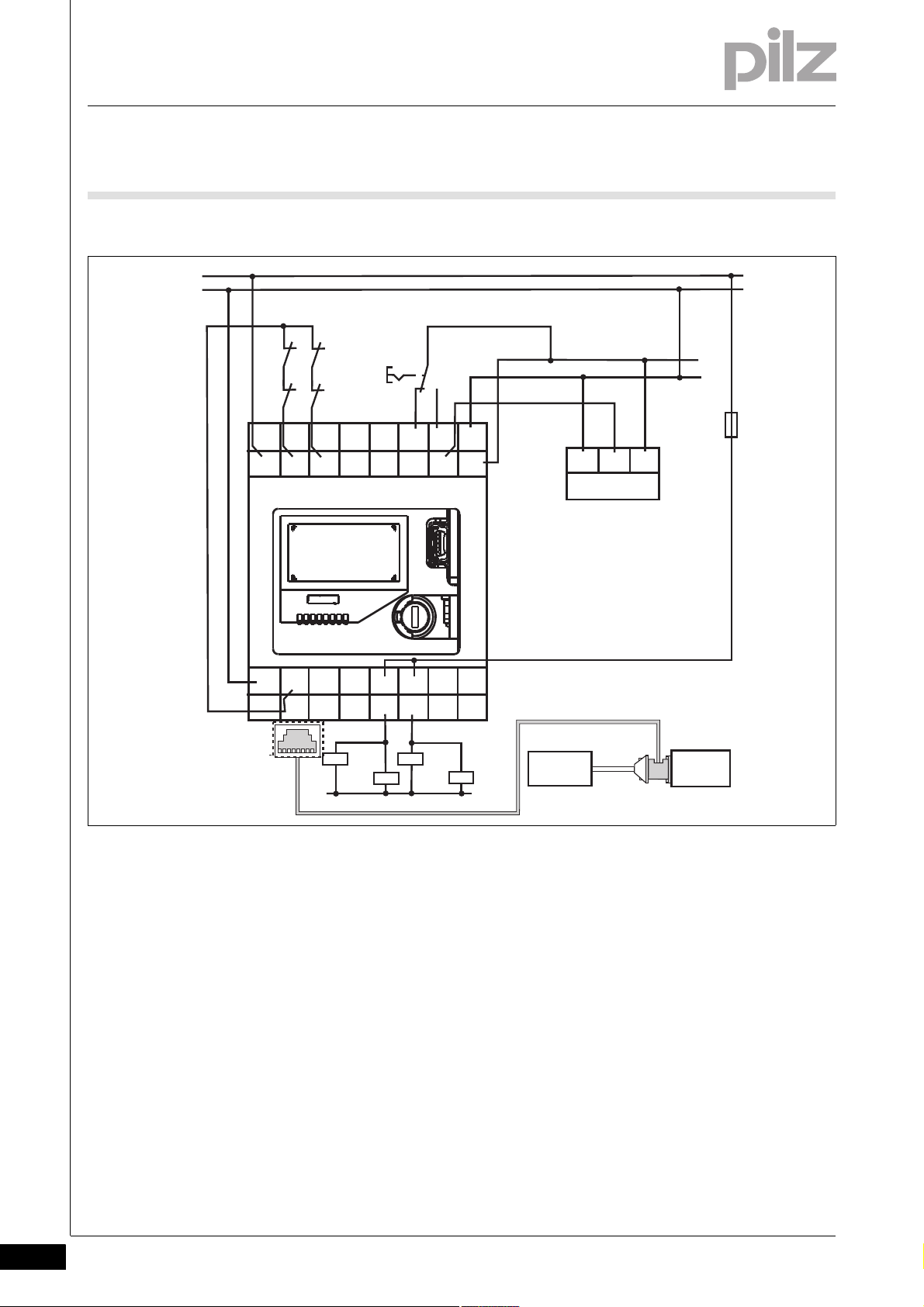
9Examples
L+
L-
K3
K4
23 21
13
11
Y13
A2
22
24
14
S11
S21 S34
12
A1
IN2IN1
Y1 Y2
GND
Y35 Y34
Y12 Y11
Y33
Y10
Y32
Y30
Y31
K3
K4
K1
K2
K1
K2
L+
L-
IN0 V
24 V
SPS
S1
*
F1
PNOZ s30
Input
device
Drive
9.2 Incremental encoder connection
9.2.3 Connection
Connection9-_Dummy-Vorlage
* The PNOZ msi adapters are available from Pilz as accessories
9-6
Pilz GmbH & Co. KG, Felix-Wankel-Straße 2, 73760 Ostfildern, Germany
Telephone: +49 711 3409-0, Telefax: +49 711 3409-133, E-Mail: pilz.gmbh@pilz.de
Page 95

...
1001715-EN-11, 2011-11 Printed in Germany
© Pilz GmbH & Co. KG, 2011
+49 711 3409-444
support@pilz.com
Pilz GmbH & Co. KG
Felix-Wankel-Straße 2
73760 Ostfildern, Germany
Telephone: +49 711 3409-0
Telefax: +49 711 3409-133
E-Mail: pilz.gmbh@pilz.de
Internet: www.pilz.com
Technical support
In many countries we are
represented by our subsidiaries
and sales partners.
Please refer to our homepage
for further details or contact our
headquarters.
InduraNET p
®
, Pilz
®
, PIT
®
, PMCprotego
®
, PMI
®
, PNOZ
®
, Primo
®
, PSEN
®
, PSS
®
, PVIS
®
, SafetyBUS p
®
, SafetyEYE
®
, SafetyNET p
®
, the spirit of safety
®
are registered and protected trademarks
of Pilz GmbH & Co. KG in some countries. We would point out that product features may vary from the details stated in this document, depending on the status at the time of publication and the scope
of the equipment. We accept no responsibility for the validity, accuracy and entirety of the text and graphics presented in this information. Please contact our Technical Support if you have any questions.
Contact address
 Loading...