

Page 1

Speed Monitor
Up to PL e of EN ISO 13849-1
PNOZ s30
Gertebild
][Bildunterschrift_Drehzahlwchter
Speed monitor for safe monitoring of
standstill, speed, position, speed
range and direction of rotation.
Approvals
PNOZ s30
SÜDDEUTSCHLAND
Pending
Pending
Unit features
Gertemerkmale PNOZ s30
` Measured value recorded by
– Incremental encoder
– Proximity switch
` Measured variables
– Standstill
– Rotational speed
–Position
– Speed range
– Direction of rotation
` Positive-guided relay outputs
– 2 safety contacts
– 2 auxiliary contacts
` Semiconductor outputs
– 4 auxiliary outputs
` Expansion interface for 2 more safe
relay outputs
` Can be configured via the display
on the speed monitor
` Configuration is stored on a chip
card
` Display
– Current frequency
– Current position
– Warning and error messages
` Status and fault LEDs
` Incremental encoder connection
technology:
RJ-45 female connector
][Gertemerkmale_Zusatz_Datenblatt
` See order reference for unit types
Unit description
Gertebeschreibung_Drehzahlwaechter_plus_Position_Bereich
The speed monitor monitors standstill,
speed, speed range, position and direction of rotation in accordance with
EN ISO 13849-1 up to PL e and
EN IEC 62061 up to SIL CL 3.
Safety features
Sicherheitseigenschaften_multi_allgemein
The relay conforms to the following
safety criteria:
` The circuit is redundant with built-in
self-monitoring.
` The safety function remains effec-
tive in the case of a component failure.
Zulassungen
Block diagram
A1 A2
~
Power
=
S34
Reset/
Start
Feed-
back
Y1 Y2
Blockschaltbild PNOZ s30
S11 S21
0 V
24 V
RJ45
Y32 Y33 Y34 Y35
In1 In2
X6
Inputs (SEL)
Y10 Y11 Y12 Y13 Y30 Y31
GND
Initiator
Input
Select
24 V ext
0 V ext
Relay
Control
Rel. 1
Rel. 2
13
14
11
12
23
24
21
Interface
Extended Relais
22
1001758-EN-01-2010-11
Page 2

Speed Monitor
Up to PL e of EN ISO 13849-1
PNOZ s30
Function description
Funktionen_Einführung
Encoders record the measured values.
The monitoring functions are selected
via the select inputs and applied to the
measured values.
The monitoring functions are configured menu-driven using a rotary
switch. The outputs switch depending
on the configuration.
In order to extend the number of outputs an interface is available to which
a PNOZsigma expander module can
be connected.
Monitoring functions
Funktionen_Überwachungsfunktionen
The speed monitor monitors for:
` Standstill
With standstill monitoring, the output is switched on when the value
falls below the stated standstill value; if the standstill value is exceeded, the output switches off.
` Rotational speed
With overspeed monitoring, the
output switches off when the stated
value is exceeded.
` Position
Position monitoring is activated
through a monitored reset via the
reset input. The current position is
adopted and the output is switched
on.
The output will now stay switched
on provided the position is within
the configured range (position window) around position x.
` Speed range
With range monitoring, the output
switches off if the frequency is outside the configured range.
` Direction of rotation
If the direction of rotation is to be
safely detected, this function must
be linked to a safety contact.
– If "Clockwise" is configured, the
safety output is switched on during normal operation in clockwise rotation.
– If "Anti-clockwise" is configured,
the safety output is switched on
during normal operation in anti-
clockwise rotation.
A tolerance can be entered for both
directions of rotation. Within this
tolerance, the drive can run in the
wrong direction without the as-
signed output switching off.
Please note: No direction of rotation
can be detected if proximity switch-
es are used.
Incremental encoders or proximity
switches can be used to record the
values (see "Encoder types" chapter).
Reset modes
You can choose between the following
reset modes:
` Automatic reset
If an automatic reset is configured,
the output switches on automati-
cally if the speed does not reach the
limit value, for example.
` Monitored reset with rising edge
If a monitored reset with rising edge
is configured, the output switches
on if the speed does not reach the
limit value and a rising edge was
detected at S34.
` Monitored reset with falling edge
If a monitored reset with falling
edge is configured, the output
switches on if the speed does not
reach the limit value and then a fall-
ing edge was detected at S34.
Switch delay
A delay time of 0 ... 30 s can be set for
each output. The outputs will not
switch until the set time has elapsed. It
is possible to configure whether the
delay time is to be activated when
switching on, switching off, or switching on and off.
Feedback loop
The feedback loop is used to monitor
external contactors or relays. If an output is activated, it will not switch on
until the feedback loop is closed.
Hysteresis
A hysteresis of 0 ... 50 % can be entered for each function. This prevents
the outputs on the speed monitor from
bouncing if there are fluctuations
around the response value. The hysteresis becomes effective when the
output is switched on:
Switch-on value = switching threshold
– hysteresis
For the lower range limit:
Switch-on value = switching threshold
– hysteresis
Start-up suppression time
To avoid spurious output signals, during the machine's start-up phase the
evaluation of the encoder signals can
be delayed after the start (0 ... 30 s).
Switching direction on semiconductor outputs
The semiconductor outputs can be
operated in normally de-energised or
normally energised mode.
Units
The configured values can be entered
in various units. Various units can be
selected for speed and distance, depending on the axis type (linear or rotational axis).
Broken shearpin monitoring
To monitor for broken shearpins, an incremental encoder is connected to
track A and B and a proximity switch
to track Z.
Speed configuration
Funktionen_Drehzahlkonfiguration
The speed monitor is configured using
the rotary knob at the device.
Up to 9 switch functions F1 ... F9 that
are monitored simultaneously can be
configured in a parameter set.
A switch function is comprised of:
` Configured speed/standstill
` Switching threshold
` Hysteresis
The standstill value is applied for configured switch functions for which no
value is entered.
The outputs are assigned to the switch
functions.
A switch delay and the reset behaviour
can be configured for each output.
For monitoring various operating
modes, for example, up to 16 parameter sets (P0 ... P15) can be configured
with max. 9 switch functions each.
The parameter set for which the switch
functions are to be monitored is then
selected via the 4 select inputs SEL1,
SEL2, SEL4, SEL8.
If only one parameter set is used, you
should configure the parameter set
P0. Then it is not necessary to connect
a select input.
1001758-EN-01-2010-11
-2
Page 3
Speed Monitor
Up to PL e of EN ISO 13849-1
PNOZ s30
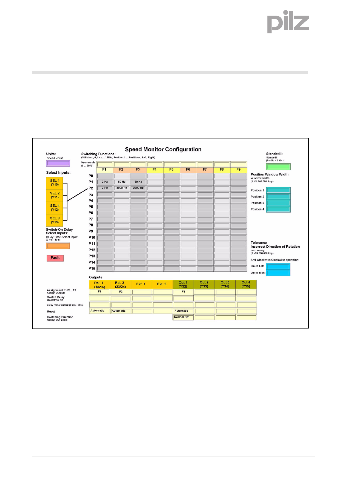
Example:
2 parameter sets for 2 operating
modes are configured:
` Set-up: P1
` Automatic mode: P2
The parameter set P2, "Automatic
mode", is selected for speed monitor-
ing (selection via the select inputs, see
next chapter "Select inputs").
The following switch functions are selected for the parameter set P2:
` F1: Standstill 2 Hz
` F2: Overspeed: 3000 Hz
` F3: Warning threshold: 2800 Hz
The following outputs are assigned to
the switch functions:
` F1: Relay output Rel. 1
` F2: Relay output Rel. 2
` F3: Semiconductor output Out 1
For a better overview of the device settings, we recommend that you fill in
the configuration overview before setting the device parameters (link to
form, see "Create configuration overview" chapter).
1001758-EN-01-2010-11
Page 4

Speed Monitor
Up to PL e of EN ISO 13849-1
PNOZ s30
Select inputs
Funktionen_Select-Eingaenge
The parameter sets are selected via
the 4 select inputs SEL1, SEL2, SEL4,
SEL8. Only one of the configured parameter sets can be selected.
Parameter set Signal statuses of the select inputs
SEL 8 SEL 4 SEL 2 SEL 1
P1 0 0 0 1
P2 0 0 1 0
P4 0 1 0 0
P8 1 0 0 0
For applications up to PL e of
EN ISO 1349-1 and up to SIL CL 3 of
EN IEC 62061 max. 4 parameter sets
can be configured: P1, P2, P4 and P8
(or P0 if only 1 parameter set is used).
The default value "Standstill" must not
be changed for all other parameter
sets.
When using these 4 select inputs, the
following safety features are met:
` The 1 from n principle ensures that
none of the parameter sets P1, P2,
Parameter set Signal statuses of the select inputs
SEL 8 SEL 4 SEL 2 SEL 1
P0 0 0 0 0
P1 0 0 0 1
P2 0 0 1 0
P3 0 0 1 1
P4 0 1 0 0
P5 0 1 0 1
P6 0 1 1 0
P7 0 1 1 1
P8 1 0 0 0
P9 1 0 0 1
P10 1 0 1 0
P11 1 0 1 1
P12 1 1 0 0
P13 1 1 0 1
P14 1 1 1 0
P15 1 1 1 1
P4 or P8 are selected due to errors
in the actuation. In the event of an
error, monitoring for standstill always occurs.
` Short circuits will be detected
` P0 is selected in the event of an
open circuit.
If necessary, the number of parameter
sets can be increased to max. 16.
These can only be used for applications up to max. PL d of
EN ISO 13849-1 and up to SIL CL 2 of
EN IEC 62061.
1001758-EN-01-2010-11
-4
Page 5

Speed Monitor
Up to PL e of EN ISO 13849-1
PNOZ s30
When using the expanded parameter sets, please note:
If an open circuit occurs when activating the select inputs, the next lowest
value is activated.
The limit values for the switch functions must therefore always be entered in ascending order. (Parameter
set 1 -> lowest values, parameter set
15 -> highest values).
Switch-on delay of the select inputs
A reaction time of between 0 and 30 s
can be entered for the select inputs.
That way it is possible to avoid invalid
signals (e.g. contact bounce) that occur when switching.
Safety guidelines for configuration
_Dummy-Vorlage
During the configuration for safety-related applications, please note:
` The maximum frequency of the en-
coders used must be entered for a
complete configuration ("Input Device type"-> "Track AB" -> "Track
AB fmax" or "Track Z" -> "Track Z
fmax" menu.)
` The standstill frequency must be
the smallest frequency entered in
the configuration.
` For parameter sets that aren't used,
the standstill values are automati-
cally transferred. These must not be
changed.
` The limit values must always be en-
tered in ascending order. (Parameter set 1 -> lowest values,
parameter set 15 -> highest values).
` During position monitoring, please
note:
– Monitored reset must be config-
ured for the position monitoring.
– A position monitoring function
must not be assigned to two outputs that are activated with different reset behaviour (one
output rising edge, one output
falling edge).
` The configurable output switch-off
delay (t
, Off) when overspeed is
do
reached will increase the speed
monitor's reaction time by the stated value (see technical details). This
must not delay the arrival of a safe
condition by more than the permitted time. The configuration of the
switch-off delay must be considered in the risk assessment as regards hazards, reaction time and
safety distance.
Chip card
Funktionen_Chipkarte
The set parameters, the name of the
configuration and the passwords are
stored on the chip card (see "Using the
chip card" chapter).
Integrated protection mechanisms
Sicherheitseigenschaften_multi_allgemein
The relay conforms to the following
safety criteria:
` The circuit is redundant with built-in
self-monitoring.
` The safety function remains effec-
tive in the case of a component failure.
Proximity switch
S_DZW_Anford_Naeherungsschalter
` The following proximity switches
can be used:
–pnp
–npn
` The proximity switches must be fit-
ted so that at least one is always
activated.
` The proximity switches must be fit-
ted so that the recorded signals
overlap.
` The supply voltage of the proximity
switches should be monitored via
the track S.
Proximity switch 1
Proximity switch 2
CAUTION!
Appropriate installation measures
should be taken to prevent a foreign
body coming between the signal encoder and the proximity switch. If not,
the foreign body could cause invalid
signals.
` Please note the values stated in the
technical details
1001758-EN-01-2010-11
Page 6

Speed Monitor
Up to PL e of EN ISO 13849-1
PNOZ s30
Incremental encoders
S_DZW_Anford_Geber
` The following encoders can be
used:
– TTL, HTL (single-ended or differ-
ential signals)
– sin/cos 1 Vss
– Hiperface
` The encoders can be connected
with or without Z index
` A proximity switch can also be con-
nected to track Z for monitoring
broken shearpins
Input device Operating
Standard encoder Monitoring
Safe encoder
Standard encoder + proximity
switch feasibility
(Z frequency)
2 proximity switches
Safe encoders with Z index
*1)
*2)
mode
PNOZ s30
1 encoder
Monitoring
2 encoders
*1)
` An output can be connected at the
encoder via track S (e.g. for fault
monitoring).
Please note the values stated in the
technical details
Adapter for incremental encoders
Drehzahlwaechter_Inkrementalgeber_Adapter
The adapter records the data between
the incremental encoder and the drive
and makes it available to the speed
monitor via the RJ-45 female connector.
Pilz supplies complete adapters as
well as ready-made cable with RJ-45
Max. achievable values
EN ISO 13849-1 PLEN IEC
62061
SIL CL
PL c (Cat. 1) PL d (Cat. 2) SIL CL 2
PL e (Cat. 3) SIL CL 3
female connectors, which can be used
when making an individual adapter.
The range of products in this area is
constantly being expanded. Please
contact us about the range of adapters
that is currently available.
Categories
Sicherheitskategorien
The following table contains details on
the maximum safety-related characteristic data that can be achieved with
the PNOZ s30 depending on the encoder type, the wiring and the operating mode.
*1) Safe encoders are encoders that
are certified in accordance with
EN 61508, EN 13849 and EN 62061.
Certain external errors must be detected in order to implement the safety
function. The encoder and evaluation
device must be compatible.
*2) The stated max. safety-related
characteristic data can only be
achieved if
` Diverse technologies / manufactur-
ers are used
` the encoder supply is evaluated via
track S.
Please note:
` The wiring must be performed in
accordance with the details in the
"Commissioning" chapter.
` A forced dynamisation must be per-
formed.
The monitored encoder must be
moved so that the signal changes
on all the connected tracks within
an 8 hour period.
Open circuits of every individual track
(A, A\, B, B\, Z, Z\ or S) are recognised
and lead to safe condition of the outputs.
For applications in accordance with
PL e and SIL CL 3, the "Overspeed"
output must be integrated into the
safety function in every operating
mode and evaluated so that a shutdown occurs if the output switches to
a safe condition.
1001758-EN-01-2010-11
-6
Page 7

Speed Monitor
Up to PL e of EN ISO 13849-1
PNOZ s30
Example for safety-related applications
Incremental encoder
Proximity switch
PNOZ s30
Safety-related characteristic data:
Input device PNOZ s30
MTTFD = MTTF Values for
2 encoder evaluation
DC = 90 %
Assumptions for the encoder system:
` Encoder is swapped after the first
fault (non-repairable system)
` 100 % of the faults that occur are
see Safety-related characteristic
data in "Technical details" chapter
Wiring
Verdrahtung_Kupferdraht_75C
Note:
` Information given in the "Technical
details" must be followed.
hazardous (worst case)
` Use copper wire that can withstand
75 °C.
Pin assignment of the RJ45 female connector
Anschlussbelegung RJ45-Buchse
RJ45 female connector
8-pole
8 1
PIN Track
1 S
2 GND
3 Z
4 A
5 A/
6 Z/
7 B
8 B/
1001758-EN-01-2010-11
Page 8

Speed Monitor
Up to PL e of EN ISO 13849-1
PNOZ s30
Supply voltage
Anschluss_Versorgungsspannung
Supply voltage AC DC
Connection of proximity switches
S_DZW_Betriebsb_Anschluss_Naeherungssch
The following proximity switches can
be connected:
` A: pnp, B: pnp
` A: npn, B: npn
` A: pnp, B: npn
` A: npn, B: pnp
24 V
0 V
RJ45
A
/A
B
/B
Z
/Z
GND
S
IN1
IN2
GND
L
N
S21
A1
A2
When connecting proximity switches
please note:
` The terminals In1, In2 and GND are
linked internally with the tracks A, B
and GND of the RJ-45 female con-
nector (see drawing).
INI_A
INI_B
A1
A2
L+
L-
` Track S should be used to monitor
the supply voltage (see drawing). A
permitted voltage range can be entered in the menu.
` Connect the proximity switch to 24
VDC of the power supply.
Connection of the incremental encoder
S_DZW_Betriebsb_Inkremen
Proceed as follows when connecting
the incremental encoder:
` The incremental encoder can be
connected via an adapter (e.g.
PNOZ msi6p) or can be connected
directly to the speed monitor.
` Use only shielded cables for all
connections
Connect incremental encoder to speed monitor
S_DZW_Betriebsb_Anschluss_Inkrementalgeber
Encoder types:
` TTL single ended
` HTL single ended
Please note:
` Tracks /A and /B must remain free
Input Device
B
A
GND
7
4
2
` Always connect GND from the in-
cremental encoder to GND from the
RJ-45 female connector.
PNOZ s30
X6
1001758-EN-01-2010-11
-8
Page 9

Speed Monitor
Up to PL e of EN ISO 13849-1
PNOZ s30
Encoder types:
` TTL differential
` HTL differential
` sin/cos 1 Vss
` Hiperface
Input Device
GND
/B
B
/A
A
5
PNOZ s30
8
7
X6
4
2
Connect incremental encoder with Z index to speed monitor
S_DZW_Betriebsb_Anschluss_Inkrementalgeber_Z-Index
Encoder types:
` TTL single Z Index
` HTL single Z Index
Please note:
` Tracks /A and /B must remain free
Input Device
GND
B
A
Z
3
PNOZ s30
7
4
2
X6
Encoder types:
` TTL diff. Z Index
` HTL diff. Z Index
` sin/cos 1 Vss Z Index
Input Device
GND
PNOZ s30
/B
B
/Z
/A
A
Z
8
7
6
5
4
3
X6
2
1001758-EN-01-2010-11
Page 10

Speed Monitor
Up to PL e of EN ISO 13849-1
PNOZ s30
Connect incremental encoder to the speed monitor via an adapter
S_DZW_Betriebsb_Anschluss_IInkremen_ueber_Adapt
The adapter (e.g. PNOZ msi6p) is connected between the incremental encoder and the drive. The output on the
adapter is connected to the RJ-45 female connector on the speed monitor.
Input Device
GND
A
/A
B
/B
Adapter
GND
18
X6
PNOZ s30
Connection of proximity switch and incremental encoder
S_DZW_Betriebsb_Anschluss_Inkrement_Naeherungssch
Encoder types:
` TTL single Z Freq. Ini pnp
` HTL single Z Freq. Ini pnp
Input Device
GND
B
A
4
3
PNOZ s30
7
X6
2
1
Drive
0 V
24 V
1001758-EN-01-2010-11
-10
Page 11

Speed Monitor
Up to PL e of EN ISO 13849-1
PNOZ s30
Encoder types:
` TTL differential Z Freq. Ini pnp
` HTL differential Z Freq. Ini pnp
` sin/cos 1 Vss Z Freq. Ini pnp
` Hiperface Z Freq. Ini pnp
Input Device
GND
/B
B
/A
A
7
5
4
PNOZ s30
8
X6
3
2
1
0 V
24 V
Reset circuit
Anschluss_Startkreis
Automatic reset Monitored reset
must only be configured
Feedback circuit
Rueckfuehrkreis
S3
S11
S34
Link Contacts from external contactors
Y1
Y2
S11
Y1
Y2
S11
13 (23)
14
24
K5
K6
K5
K6
L+
L-
1001758-EN-01-2010-11
Page 12

Speed Monitor
Up to PL e of EN ISO 13849-1
PNOZ s30
Terminal configuration
Klemmenbelegung PNOZ s30
5
X3X1
IN1
IN2 GND Y10
A1
Y1 IY2 Y32
PNOZ s30
Y12Y13 Y30
Y11
Y34Y35 Y31
Y33
X6
2
1
A2
S11 S21 11
X2X6
Left: Side view, centre: Front view without cover, right: Front view with cover
3
4
13S34 21
23
14 22
12
24
X4
X3X1
IN1
IN2 GND Y10
A1
Y1 IY2 Y32
PNOZ s30
Power
In1
In2
Rel 1
Rel 2
Fault
A2
S11 S21 11
X2X6
Y12Y13 Y30
Y11
Y34Y35 Y31
Y33
13S34 21
23
14 22
12
24
X4
1001758-EN-01-2010-11
-12
Page 13

Speed Monitor
Up to PL e of EN ISO 13849-1
PNOZ s30
Installation
][Montage_Drehzahlwächter
Install base unit without contact expander module:
` Ensure that the plug terminator is
inserted at the side of the unit.
Connect base unit and PNOZsigma
contact expander module:
` Remove the plug terminator at the
side of the base unit and at the contact expander module.
` Connect the base unit and the con-
tact expander module to the supplied connector before mounting
the units to the DIN rail.
Control cabinet installation
` The unit should be installed in a
control cabinet with a protection
type of at least IP54.
` It is preferable to install the device
on a horizontal DIN rail in order to
ensure the best possible convection.
` Use the locking element on the rear
of the device to attach it to the DIN
rail.
` Push the device upwards or down-
wards before lifting it from the DIN
rail.
Dimensions
Abmessungen
*with spring-loaded terminals
98 (3.86")
* 100 (3,94")
120 (4.72")
45
(1.77")
1001758-EN-01-2010-11
Page 14

Speed Monitor
Up to PL e of EN ISO 13849-1
PNOZ s30
Notice
][Wichtig_PDB
This data sheet is only intended for use
during configuration. Please refer to
the operating manual for installation
and operation.
Service life graph
Lebensdauerkurve_Rela is_Text vor Kurv e
The service life graphs indicate the
number of cycles from which failures
due to wear must be expected. The
wear is mainly caused by the electrical
load; the mechanical load is negligible.
Lebensdauerkurve_Relais_Text nach Kurve_SIS442 Bsp
Example
` Inductive load: 0.2 A
` Utilisation category: AC15
` Contact service life: 700 000 cycles
Provided the application requires fewer than 700 000 cycles, the PFH value
10
1
Courant coupé (A)
D Nennbetriebstrom (A)
GB Nominal operating current (A)
F
0.1
E Corriente nominal de servicio (A)
I Corrente di esercizio nominale (A)
NL Nominale bedrijfsstroom (A)
10 100 1000 10000
D Schaltspielzahl x 10
GB Cycles x 10
F Nombre de manuvres x 10
AC15: 230 V
DC13: 24 V
3
3
(see technical details) can be used in
the calculation.
To increase the service life, sufficient
spark suppression must be provided
on all output contacts. With capacitive
loads, any power surges that occur
Lebensdauerkurve PNOZ s30
DC1: 24 V
AC1: 230 V
E Número de ciclos x 10
I Numero dei cicli di commutazione x 10
3
NL Aantal schakelingen x 10
3
3
must be noted. With contactors, use
freewheel diodes for spark suppression.
Technical details PNOZsigma
3
Technical details
Electrical data
Supply Voltage
Supply voltage U
AC/DC 24 - 240 V
B
Voltage tolerance -15 %/+10 %
Power consumption at U
Power consumption at U
Max. inrush current at U
AC 9.0 VA
B
DC 5.5 W
B
B
10.00 A
Frequency range AC 50 - 60 Hz
Residual ripple DC 160 %
Continuous duty 100 %
Voltage and current at
Reset circuit DC: 24.0 V 5.0 mA
Feedback loop DC: 24.0 V 5.0 mA
Max. inrush current impulse
0.06 A
Feedback loop 0.06 A
Min. unit fuse protection 1.00 A
Max. unit fuse protection F1 Max. cable cross section
Proximity switch input
Number of inputs 2
1001758-EN-01-2010-11
-14
Page 15

Speed Monitor
Up to PL e of EN ISO 13849-1
PNOZ s30
Proximity switch input
Input signal level
Signal level at "1" 11 - 30 V
Signal level at "0" -3 - 5 V
Input resistance 22 kOhm
Input's frequency range 0 - 1,000 kHz
Configurable monitoring frequency
without hysteresis 0 - 1,000 kHz
Input for incremental encoder/proximity switch (RJ45 connector)
Number of inputs 1
Input signal level 0.5 - 30.0 Vss
Phase position for the differential signals A,/A and B,/B 90° ±30°
Overload protection -30 - 30 V
Input resistance 20.0 kOhm
Input's frequency range 0 - 1,000 kHz
Configurable monitoring frequency
without hysteresis 0 - 1,000 kHz
Connection type (incremental encoder) RJ45 female connector, 8-pin
Select inputs
Number of inputs 4
Input signal level
Signal level at "1" 15 V
Signal level at "0" 5 V
Input current 5 mA
Semiconductor outputs
Number 4
Semiconductor outputs (short circuit proof) 24.0 V DC,50 mA
External supply voltage 24.0 V DC
Voltage tolerance -20% / +20%
Relay outputs
Number of output contacts
Safety contacts (S) instantaneous: 2
Auxiliary contacts (N/C): 2
Utilisation category in accordance with EN 60947-4-1
Safety contacts: AC1 at 240 V I
Safety contacts: DC1 at 24 V I
Auxiliary contacts: AC1 at 240 V I
Auxiliary contacts: DC1 at 24 V I
Utilisation category in accordance with EN 60947-5-1
Safety contacts: AC15 at 230 V I
Safety contacts: DC13 at 24 V (6 cycles/min) I
Auxiliary contacts: AC15 at 230 V I
Auxiliary contacts: DC13 at 24 V (6 cycles/min) I
Conventional thermal current 4.0 A
Contact material AgCuNi + 0.2 µm Au
: 0.01 A , I
min
: 1000 VA
P
max
: 0.01 A , I
min
: 100 W
P
max
: 0.01 A , I
min
P
: 1000 VA
max
: 0.01 A , I
min
: 100 W
P
max
: 3.0 A
max
: 4.0 A
max
: 3.0 A
max
: 4.0 A
max
max
max
max
max
: 4.0 A
: 4.0 A
: 4.0 A
: 4.0 A
1001758-EN-01-2010-11
Page 16

Speed Monitor
Up to PL e of EN ISO 13849-1
PNOZ s30
Relay outputs
External contact fuse protection (IK = 1 kA) to EN 60947-5-1
Blow-out fuse, quick
Safety contacts: 6 A
Auxiliary contacts: 6 A
Blow-out fuse, slow
Safety contacts: 4 A
Auxiliary contacts: 4 A
Circuit breaker 24 VAC/DC, characteristic B/C
Safety contacts: 4 A
Auxiliary contacts: 4 A
Timers
Switch-on delay
with automatic reset typ. 35 ms
with automatic reset max. 50 ms
with automatic reset after power on typ. 3,000 ms
with automatic reset after power on max. 4,000 ms
with manual reset typ. 60 ms
with manual reset max. 100 ms
Delay-on de-energisation
with power failure typ. U
with power failure max. U
with power failure typ. U
with power failure max. U
after the safety function is triggered, typ. 8 ms
after the safety function is triggered, max. 15 ms
Recovery time at max. switching frequency 1/s
after power failure 1000 ms
Reaction time after limit value is exceeded 1/f_ist + 16 ms
Waiting period with a monitored reset
with rising edge 30 ms
with falling edge 30 ms
Min. start pulse duration with a monitored reset
with rising edge 30 ms
with falling edge 30 ms
Supply interruption before de-energisation 15 ms
Switch delay (selectable) 0 - 30 s
Switch-on delay on the function inputs (selectable) 0 - 30 s
Start-up suppression time (selectable) 0 - 30 s
Environmental data
EMC EN 60947-5-1, EN 61000-6-2, EN 61000-6-3
Vibration to EN 60068-2-6
Frequency 10 - 55 Hz
Amplitude 0.35 mm
Climatic suitability EN 60068-2-78
Airgap creepage in accordance with EN 60947-1
Pollution degree 2
Overvoltage category III / II
Rated insulation voltage 250 V
Rated impulse withstand voltage 4.00 kV
Ambient temperature -10 - 55 °C
Storage temperature -40 - 85 °C
Protection type
Mounting (e.g. cabinet) IP54
Housing IP30
Terminals IP20
AC/DC: 24 V 25 ms
B
AC/DC: 24 V 50 ms
B
AC : 240 V 100 ms
B
AC : 240 V 150 ms
B
1001758-EN-01-2010-11
-16
Page 17

Speed Monitor
Up to PL e of EN ISO 13849-1
PNOZ s30
Mechanical data
Housing material
Housing PC
Front PC
Cross section of external conductors with screw terminals
1 core flexible 0.25 - 2.50 mm² , 24 - 12 AWG No. 750330
2 core, same cross section, flexible:
with crimp connectors, without insulating sleeve 0.25 - 1.00 mm² , 24 - 16 AWG No. 750330
without crimp connectors or with TWIN crimp connectors 0.20 - 1.50 mm² , 24 - 16 AWG No. 750330
Torque setting with screw terminals 0.50 Nm No. 750330
Connection type spring-loaded terminal No. 751330
screw terminal No. 750330
Spring-loaded terminals: Terminal points per connection 2 No. 751330
Stripping length 9 mm No. 751330
Dimensions
Height 100.0 mm No. 751330
98.0 mm No. 750330
Width 45.0 mm
Depth 120.0 mm
Weight 410 g
Si-Kennzahlen_alle
Safety characteristic data
EN ISO 13849-1PLEN 954-1
Unit Operating mode
PNOZ s30 Monitoring 1 input de-
vice
PNOZ s30 Monitoring 2 input de-
vices
All the units used within a safety function must be considered when calculating the safety characteristic data.
Technische Daten_Satz No rmen
The standards current on 2009-06 apply.
Bestelldaten PNO Z s30
Order reference
Type Terminals Order No.
PNOZ s30 With screw terminals 750 330
PNOZ s30 C With spring-loaded terminals 751 330
Tools
PNOZ s terminator plug Terminator 10 pieces 750 010
PNOZmulti Chipcard Chip card 8 kB 779 201
PNOZmulti Chipcard Set Chip card 8 kB 10 pieces 779 200
PNOZmulti Chipcard Chip card 32 kB 779 211
PNOZmulti Chipcard Set Chip card 32 kB 10 pieces 779 212
Chipcard Holder Chip card holder 779 240
PNOZmulti Seal Chip card seal 10 pieces 779 250
PNOZ s Set3 Screw Loaded Terminals Set of plug-in screw ter-
PNOZ s Set3 Spring Loaded Terminals Set of plug-in spring-
PL d (Cat. 2) Cat. 2 SIL CL 2 3.28E-08 20
PL e (Cat. 3) Cat. 3 SIL CL 3 1.50E-08 20
Si_Kennzahlen_Erläuterung
minals
loaded terminals
Category
EN IEC 62061
SIL CL
1 piece 750014
1 piece 751014
PFH [1/h] tM [year]
1001758-EN-01-2010-11
 Loading...