

Page 1

20 772-04
PNOZ po3p, PNOZ po4p
4
D Betriebsanleitung
4
GB Operating instructions
4
F Manuel d'utilisation
4 E Instrucciones de uso
4 I Istruzioni per l`uso
4 NL Gebruiksaanwijzing
Das Erweiterungsmodul PNOZ po3p,
PNOZ po4p
dient zusammen mit einem Basisgerät des
modularen Sicherheitssystems PNOZpower
dem sicherheitsgerichteten Unterbrechen
eines Sicherheitsstromkreises.
Das Erweiterungsmodul darf nur mit einem
Basisgerät oder Ansteuermodul des modularen Sicherheitssystems PNOZpower verwendet werden.
Das Erweiterungsmodul ist bestimmt für den
Einsatz in
• NOT-AUS-Einrichtungen
• Sicherheitsstromkreisen nach EN 60204-1
(VDE 0113-1) und IEC 60204-1
Die zu realisierende Kategorie nach EN 954-1
ist abhängig von der Kategorie des Grundgeräts. Sie kann vom Erweiterungsmodul nicht
überschritten werden.
Zu Ihrer Sicherheit
Das Erweiterungsmodul PNOZ po3p, PNOZ
po4p erfüllt zusammen mit einem Basisgerät
oder Ansteuermodul des modularen
Sicherheitssystems PNOZpower alle
notwendigen Bedingungen für einen sicheren
Betrieb.
Beachten Sie jedoch nachfolgend aufgeführte Sicherheitsbestimmungen:
• Installieren und nehmen Sie das Gerät nur
dann in Betrieb, wenn Sie mit dieser
Betriebsanleitung und den geltenden
Vorschriften über Arbeitssicherheit und
Unfallverhütung vertraut sind.
• Verwenden Sie das Gerät nur gemäß
seiner Bestimmung. Beachten Sie dazu
auch die Werte im Abschnitt "Technische
Daten".
• Halten Sie beim Transport, bei der
Lagerung und im Betrieb die Bedingungen
nach EN 60068-2-6 ein (siehe "Technische
Daten").
• Sorgen Sie bei allen kapazitiven und
induktiven Verbrauchern für eine ausreichende Schutzbeschaltung.
• Öffnen Sie nicht das Gehäuse und
nehmen Sie auch keine eigenmächtigen
Umbauten vor.
• Schalten Sie bei Wartungsarbeiten (z. B.
beim Austausch von Schützen) unbedingt
die Versorgungsspannung ab oder öffnen
Sie den Eingangskreis.
Beachten Sie unbedingt die Warnhinweise in
den anderen Abschnitten dieser Anleitung.
Diese Hinweise sind optisch durch Symbole
hervorgehoben.
Wichtig: Beachten Sie die Sicherheitsbestimmungen, sonst erlischt
jegliche Gewährleistung.
The expander module PNOZ po3p,
PNOZ po4p
in conjunction with an base unit from the
PNOZpower modular safety system, is used
for the safety-related interruption of a safety
circuit.
The expander module only be used with a
base unit or control module in the
PNOZpower modular safety system.
The expander module is intended for use in
• E-STOP systems
• Safety circuits conforming to EN 60204-1
(VDE 0113-1) and IEC 60204-1
The category to be implemented in
accordance with EN 954-1 depends on the
category of the base module. It cannot be
exceeded by the expander module..
For your safety
The expander module PNOZ po3p, PNOZ
po4p, in conjunction with a base unit or
control module from the PNOZpower
modular safety system, meets all the
necessary conditions for safe operation.
However, always ensure the following safety
requirements are met:
• Only install and commission the unit if you
are familiar with the information in these
operating instructions, as well as the
relevant regulations concerning health and
safety at work and accident prevention.
• Only use the unit for the purpose for which
it is intended. Please note also the values
stated in the “Technical details” section.
• Transport, storage and operating
conditions should all conform to EN
60068-2-6 (see “Technical details”).
• Sufficient fuse protection must be provided
on all capacitive and inductive loads.
• Do not open the housing or make any
unauthorised modifications.
• When carrying out maintenance work
(e.g. exchanging contactors), make sure
you switch off the supply voltage or open
the input circuit.
You must observe the warning notes given in
other parts of these operating instructions.
These notes are highlighted via symbols.
Notice: Failure to comply with the
safety requirements will render the
guarantee invalid.
Module d’expansion PNOZ po3p,
PNOZ po4p
utilisé avec l’appareil de base, il sert à
interrompre de manière sûre un circuit de
sécurité. Les contacts de sécurité sont
commandés par l’appareil de base.
Le module d’extension doit uniquement être
utilisé avec un appareil de base ou un
module de commande du système de
sécurité modulaire PNOZpower.
Le module d’extension est conçu pour les
applications suivantes :
• Circuits d’arrêt d’urgence
• Circuits de sécurité selon les normes
EN 60204-1 (VDE 0113-1) et IEC 60204-1
La catégorie à réaliser selon l’EN 954-1
dépend de la catégorie de l’appareil de base.
Elle ne peut pas être dépassée par le module
d’extension.
Pour votre sécurité
Le module d’extension PNOZ po3p, PNOZ
po4p satisfait à toutes les conditions
nécessaires pour un fonctionnement
sécuritaire.
Toutefois, vous êtes tenu de respecter les
prescriptions de sécurité suivantes :
• Vous n’installerez l’appareil et ne le
mettrez en service qu’après vous être
familiarisé avec le présent manuel
d’utilisation et les prescriptions en vigueur
sur la sécurité du travail et la prévention
des accidents.
• N'utilisez l'appareil que conformément à sa
définiton. A ce sujet, respectez les valeurs
indiquées dans les "Caractéristiques
techniques".
• Pour le transport, le stockage et
l'utilisation, respectez les exigences de la
norme EN 60068-2-6 (voir
„Caractéristiques techniques“).
• Veillez à ce que les consommateurs
capacitifs et inductifs aient une protection
suffisante.
• N’ouvrez pas le boîtier et n'effectuez pas
de modifications non autorisées.
• En cas de travaux de maintenance (par
ex. remplacement des contacteurs) coupez
impérativement la tension d’alimentation ou
ouvrez le circuit d’entrée (action sur le BP
d’arrêt d’urgence), sinon un réarmement
inopiné du relais est possible en cas
d’erreur de câblage.
Respectez impérativement les
avertissementsdans les autres paragraphes
du présent manuel d’utilisation. Ces
avertissements sont signalés par des
symboles visuels.
Important : Respectez les consignes
de sécurité, sinon la garantie devient
caduque.
- 1 -
Page 2
Gerätebeschreibung
Sicherheitseigenschaften:
Das Schaltgerät erfüllt folgende Sicherheitsanforderungen:
• Schaltung ist redundant mit Selbstüberwachung aufgebaut (EN 954-1, Kategorie 4).
• Sicherheitseinrichtung bleibt auch bei
Ausfall eines Bauteils wirksam.
• Bei jedem Ein-Aus-Zyklus der Maschine
wird automatisch überprüft, ob die Relais
der Sicherheitseinrichtung richtig öffnen
und schließen.
Gerätemerkmale:
• Relaisausgänge:
- PNOZ po3p: 3 Sicherheitskontakte (S),
zwangsgeführt, 1 Hilfskontakt (Ö)
• sichere Trennung der Sicherheitskontakte
13-14, 23-24, 33-34 und des Hilfskontakts
41-42 vom PNOZpower-Bus
- PNOZ po4p: 4 Sicherheitskontakte (S),
zwangsgeführt
• sichere Trennung der Sicherheitskontakte
13-14, 23-24, 33-34, 43-44 vom
PNOZpower-Bus
•
Statusanzeige für Schaltzustand Kanal 1/2,
Versorgungsspannung und Störung
• Eingangskreise, Rückführkreis und
Versorgungsspannung auf PNOZpowerBus geführt
• max. 4 Erweiterungsmodule an ein
Basisgerät anschließbar
• Verbindung zum Basisgerät und zwischen
den Erweiterungsmodulen über
PNOZpower-Bus durch Steckbrücken auf
der Geräterückseite
Unit description
Safety features:
The relay fulfils the following safety
requirements:
• The circuit is redundant, with built-in selfmonitoring (EN 954-1, Category 4).
• The safety function remains effective in the
case of a component failure.
• The correct opening and closing of the
safety function relays is tested
automatically in each on-off cycle.
Unit features:
• Relay outputs:
- PNOZ po3p: 3 safety contacts (N/O),
and 1 auxiliary contact (N/C), positiveguided.
• Safe separation of safety contacts 13-14,
23-24, 33-34 and of auxiliary contact 41-42
from PNOZpower bus
- PNOZ po4p: 4 safety contacts (N/O),
positive-guided.
• Safe separation of safety contacts 13-14,
23-24, 33-34, 43-44 from PNOZpower bus
•
Channels 1/2 status display,
and faults
• Input circuits, feedback loop and power
supply fed on the PNOZpower bus
• A maximum of 4 expander modules can be
connected to a base unit.
• Connection to the base unit, and between
expander modules via the PNOZpower
bus employing jumpers on the rear face of
the unit.
power supply
Description de l’appareil
Propriétés de sécurité :
Le bloc logique de sécurité satisfait aux
exigences de sécurité suivantes :
• Commutation redondante avec
autosurveillance (EN 954-1, catégorie 4).
• Le dispositif de sécurité reste actif, même
en cas de défaillance d’un composant.
• L’ouverture et la fermeture correctes des
relais du dispositif de sécurité sont
contrôlées automatiquement à chaque
cycle marche/arrêt de la machine.
Caractéristiques de l’appareil :
•
Sorties à relais :
- PNOZ po3p : 3 contacts de sécurité (F)
,
1 contact de info (O), à contacts liés
• séparation galvanique entre les contacts de
sécurité 13-14, 23-24, 33-34, le
info
41-42 et le bus PNOZpower
- PNOZ po4p :
4 contacts de sécurité (F)
à contacts liés
• séparation galvanique entre les contacts de
sécurité 13-14, 23-24, 33-34, 43-44 et le bus
PNOZpower
•
Visualisation de l’état de commutation des
canaux 1/2,
de l’alimentation en tension et
des défauts
•
Circuits d’entrée, boucle de retour et alimentation en tension par le bus
PNOZpower
•
Possibilité de raccorder jusqu’à 4 modules
d’extension maximum sur un appareil de
base
•
Liaison vers l’appareil de base et entre les
modules d’extension via le bus
PNOZpower au moyen de cavaliers de
pontage situés sur la face arrière de
l’appareil
contact de
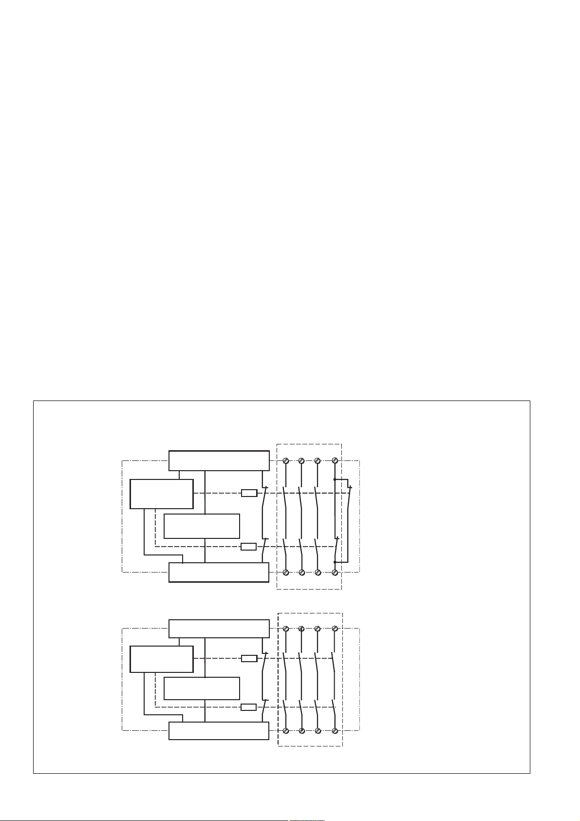
*Sichere Trennung nach EN 60947-1, 6 kV/*Safe separation in accordance with EN 60947-1, 6 kV/
*Séparation galvanique selon EN 60947-1, 6 kV
PNOZ po3p
*
41
42
43
*
PNOZ po4p
Eingangskreise
Input circuit
circuit d'entree
Rückführkreis
feedback control loop
boucle de retour
Eingangskreise
Input circuit
circuit d'entree
Rückführkreis
feedback control loop
boucle de retour
PNOZpower-Bus
13 23 33
K1
K2
PNOZpower-Bus
14 24 34
13 23 33
PNOZpower-Bus
K1
K2
Innenschaltbild
PNOZpower-Bus
14 24 34
44
Internal wiring diagram Schéma interne
- 2 -
Page 3
Funktionsbeschreibung
Arbeitsweise:
Die Sicherheitskontakte werden vom
Basisgerät angesteuert. Versorgungsspannung, Eingangskreise und Rückführkreis
werden über den PNOZpower-Bus geführt.
Sobald die Versorgungsspannung anliegt
und die Eingangskreise am Basisgerät
geschlossen sind, gehen die beiden
Ausgangsrelais K1 und K2 in Arbeitsstellung.
• PNOZ po3p
Die Sicherheitskontakte 13-14, 23-24, 3334 schließen und der Hilfskontakt 41-42
öffnet. Werden die Eingangskreise
geöffnet, fallen die Relais K1 und K2 ab.
Die zwangsgeführten Sicherheitskontakte
13-14, 23-24, 33-34 öffnen und der
Hilfskontakt 41-42 schließt.
• PNOZ po4p
Die Sicherheitskontakte 13-14, 23-24, 3334 und 43-44 schließen. Werden die
Eingangskreise geöffnet, fallen die Relais
K1 und K2 ab. Die zwangsgeführten
Sicherheitskontakte 13-14, 23-24, 33-34
und 43-44 öffnen.
Function
Operation:
The base unit controls the safety contacts.
Power supply, input circuits and feedback
loop are fed via the PNOZpower bus.
As soon as the power supply is detected and
the input circuits on the base unit are made,
both output relays K1 and K2 are operational.
• PNOZ po3p
The safety contacts 13-14, 23-24 and 3334 are closed and the auxiliary contact 4142 is open. If the input circuits become
open, the K1 and K2 relay(s) drop(s) out.
The positive-guided safety contacts 13-14,
23-24 and 33-34 will be opend and the
auxiliary contact 41-42 closes
• PNOZ po4p
The safety contacts 13-14, 23-24, 33-34
and 43-44 are closed. If the input circuits
become open, the K1 and K2 relay(s)
drop(s) out. The positive-guided safety
contacts 13-14, 23-24, 33-34 and 43-44
will be opend.
Descriptif du fonctionnement
Fonctionnement :
La tension d’alimentation, les circuits
d’entrée et la boucle de retour dépendent du
bus PNOZpower.
Dès que la tension d’alimentation est
appliquée et que les circuits d’entrée de
l’appareil de base sont fermés, les deux
relais de sortie K1 et K2 passent en position
de travail.
• PNOZ po3p
Les contacts de sécurité 13-14, 23-24 et
33-34 sont fermés et le contact d'info (41-
42) est ouvert.
Si l’un des circuits d’entrée est ouvert, les
relais K1 et K2 retombent. Les contacts de
sécurité à contact liés 13-14, 23-24 et 3334 s’ouvrent et le contact d'info (41-42) se
ferme.
• PNOZ po4p
Les contacts de sécurité 3-14, 23-24, 3334 et 43-44 sont fermés.
Si l’un des circuits d’entrée est ouvert, les
relais K1 et K2 retombent. Les contacts de
sécurité à contact liés 13-14, 23-24, 33-34
et 43-44 s’ouvrent.
Sicherheitsschaltgerät montieren
Achtung! Montieren Sie das
Sicherheitsschaltgerät in einen
Schaltschrank mit einer Schutzart von
mindestens IP54.
• Befestigen Sie das Gerät mit Hilfe der zwei
Rastelemente auf der Rückseite auf einer
Normschiene.
• Montieren Sie das Gerät auf eine waagrechte Tragschiene. Bei anderen Einbaulagen können die in den techn. Daten
angegebenen Werte für das Schaltvermögen nicht eingehalten werden.
• Das Erweiterungsmodul PNOZ po3p,
PNOZ po4p kann an beliebiger Stelle des
modularen Sicherheitssystems
PNOZpower montiert werden.
• Auf der Geräterückseite befinden sich 2
Buchsen. Das Erweiterungsmodul PNOZ
po3p, PNOZ po4p wird mit den anderen
Geräten des modularen Sicherheitssystems PNOZpower über die mitgelieferten Steckbrücken verbunden.
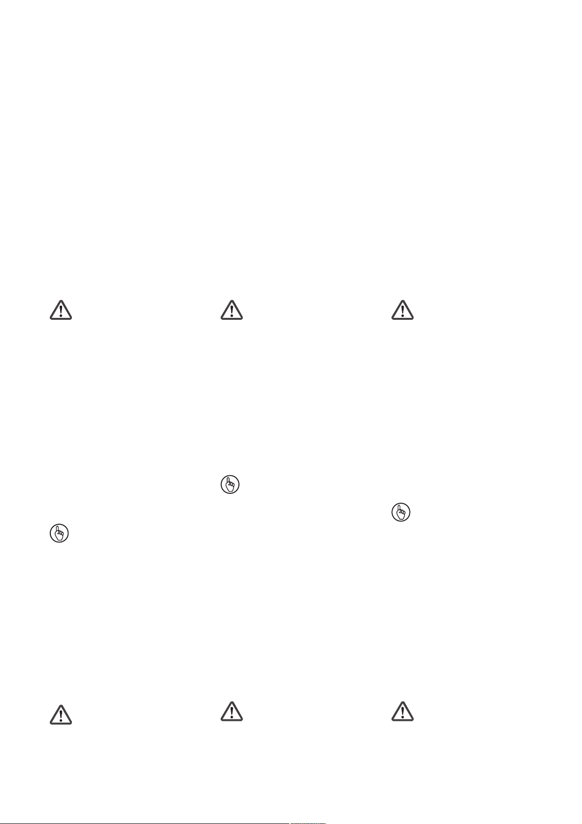
Wichtig: Auf das erste und letzte
Gerät muss ein Abschlussstecker
gesteckt werden (siehe Fig. "Montage
des PNOZ po3p, PNOZ po4p“)!
• Nur Abschlussstecker für das modulare
Sicherheitssystem PNOZpower verwenden
(Aufdruck Sach-Nr. 95579).
• Maximalbestückung eines PNOZpowerSystems:
- 1 Grundgerät
- 4 Erweiterungsmodule
- 1 Netzgerät
Installing the safety relay
Caution! The safety relay must be
installed in a control cabinet with a
minimum protection type of IP54.
• Use the two notches on the rear of the unit
to attach it to a DIN-rail.
• Fit the unit to a horizontal DIN rail. In other
mounting positions, the values given in the
technical details for the switching capability
may not be achieved.
• The PNOZ po3p , PNOZ po4p expander
module can be installed in any position on
the PNOZpower modular safety system.
• There are 2 sockets on the rear of the unit.
Connect the PNOZ po3p, PNOZ po4p
expander module to other units in the
PNOZpower modular safety system with
the jumpers supplied.
Important: Be sure to plug a
terminator in to the first and last units
(see Fig. "Installation PNOZ po3p,
PNOZ po4p“)!
• Only use terminators for the PNOZpower
modular safety system (Catalogue item no.
95579).
• Maximum hardware in a PNOZpower
system:
- 1 base unit
- 4 expander modules
- 1 power supply unit
Installer le bloc logique de sécurité
Attention! Installez le bloc logique de
sécurité dans une armoire d’indice de
protection au moins IP54.
• Montez l'appareil sur un rail DIN à l'aide du
système de fixation situé au dos du relais.
• Montez l’appareil sur un profilé support
horizontal. Les autres positions de
montage ne permettent pas de respecter
les valeurs de commutation indiquées
dans les caractéristiques techniques.
• Le module d’extension PNOZ po3p, PNOZ
po4p peut être installé en n’importe quel
point du système de sécurité modulaire
PNOZpower.
• La face arrière du PNOZ po3p, PNOZ
po4p comporte 2 douilles. Le module
d’extension PNOZ po3p, PNOZ po4p est
relié aux autres appareils du système de
sécurité modulaire PNOZpower par le
biais des cavaliers de pontage fournis.
Important : le premier et le dernier
appareil doivent être pourvus d’une
fiche de terminaison (voir fig.
«Montage du PNOZ po3p, PNOZ
po4p») !
• Utilisez uniquement les fiches de terminaison prévues pour le système de sécurité
modulaire PNOZpower (Référence :
95579).
• Équipement maximal d’un système
PNOZpower :
- 1 appareil de base
- 4 modules d’extension
- 1 bloc d’alimentation
Sicherheitsschaltgerät
inbetriebnehmen
Inbetriebnahme vorbereiten:
Beachten Sie bei der Inbetriebnahme:
Achtung: Die steckbaren Anschlussklemmen nur im spannungslosen
Zustand ziehen und stecken.
• Vor die Ausgangskontakte eine
Sicherung (s. technische Daten)
schalten, um das Verschweißen der
Kontakte zu verhindern.
Commissioning the safety relay
Preparing for commissioning:
When commissioning, please note the
following:
Caution: Only connect and
disconnect the plug-in terminals when
isolated from the mains.
• To prevent contact welding, a fuse
should be connected before the output
contacts (see technical details).
- 3 -
Mettre en service le bloc logique de
sécurité
Préparer la mise en service :
Points importants pour la mise en service :
Attention : Ne branchez et
débranchez les borniers de
raccordement débrochables que
lorsque l’alimentation est coupée.
• Raccordez un fusible (voir les caracté-
ristiques techniques) avant les contacts
de sortie afin d’éliminer tout risque de
fusion.
Page 4
Netzgerät
Power Supply
Bloc
d'alimentation
Basisgerät
Base Unit
Appareil
de base
Erweiterungsmodul 1
Expander modul 1
Module d'expansion 1
PNOZ po3p
PNOZ po4p
Erweiterungsmodul 4
Expander modul 4
Module d'expansion 4
95579
Abschlussstecker
Terminator
Fiche de
terminaison
Montage des PNOZ po3p, PNOZ po4p
• Keine kleinen Ströme (z. B. 30 mA) mit
Kontakten schalten, über die zuvor große
Ströme geführt wurden.
• Leitungsmaterial aus Kupferdraht mit einer
Temperaturbeständigkeit von 60/75 °C
verwenden.
• Das Anzugsdrehmoment der Schrauben
auf den Anschlussklemmen muss 0,5 Nm
betragen.
• Angaben im Kapitel "Technische Daten"
unbedingt einhalten.
Betrieb
Das Gerät ist betriebsbereit, wenn
• die Versorgungsspannung über den
PNOZpower-Bus anliegt (LED "POWER"
leuchtet),
• die Eingangskreise am Basisgerät
geschlossen sind.
Statusanzeigen:
• LEDs "K1" und "K2" leuchten:
- PNOZ po3p:
Sicherheitskontakte 13-14, 23-24 und
33-34 sind geschlossen, Hilfskontakt 4142 ist geöffnet.
- PNOZ po4p:
Sicherheitskontakte 13-14, 23-24, 33-34
und 43-44 sind geschlossen.
• LEDs "K1" und "K2" erlöschen:
- PNOZ po3p:
Sicherheitskontakte 13-14, 23-24 und
33-34 sind geöffnet, Hilfskontakt 41-42
ist geschlossen.
- PNOZ po4p:
Sicherheitskontakte 13-14, 23-24, 33-34
und 43-44 sind geöffnet.
Fehleranzeige:
• LED "FAULT" leuchtet: Fehlfunktion der
Kontakte
95425
Steckbrücke
Link
Cavalier de pontage
Installation PNOZ po3p, PNOZ po4p
• Don’t switch low currents (e.g. 30 mA)
using contacts that have been used
previously with high currents.
• Use copper wire that can withstand
60/75 °C.
• The torque setting on the connection
terminals should be 0.5 Nm.
• Information given in the "Technical details"
must be followed.
Operation
The unit is ready for operation when:
• the power supply via the PNOZpower bus is
present ("POWER" LED illuminates)
• the input circuits on the base unit are
made.
Status indicators:
•"K1" and "K2" lights:
- PNOZ po3p:
Safety contacts 13-14, 23-24 and 33-34
are closed, the auxiliary contact 41-42 is
open.
- PNOZ po4p:
Safety contacts 13-14, 23-24, 33-34 and
43-44 are closed.
•"K1" and "K2" goes out:
- PNOZ po3p:
Safety contacts 13-14, 23-24 and 33-34
are opend, the auxiliary contact 41-42 is
closed
- PNOZ po4p:
Safety contacts 13-14, 23-24, 33-34 and
43-44 are open.
Fault indicator:
•"FAULT" LED illuminates: Contact function
faulty
95579
Abschlussstecker
Terminator
Fiche de
terminaison
Montage du PNOZ po3p, PNOZ po4p
• Ne commutez pas de courants de faible
intensité (par ex. 30 mA) avec des
contacts ayant servi à des courants de
forte intensité.
• Utilisez uniquement des fils de câblage en
cuivre résistant à des températures de
60/75 °C.
• Le couple de serrage des vis doit être de
0,5 Nm au niveau des borniers.
• Respectez impérativement les instructions
données dans le chapitre "Caractéristiques
techniques".
Fonctionnement
L’appareil est prêt à fonctionner lorsque
• la tension d’alimentation est appliquée via le
bus PNOZpower (LED "POWER" allumée)
• les circuits d’entrée de l’appareil de base
sont fermés
Affichage d'état :
•"K1" et "K2" sont allumées :
- PNOZ po3p:
Contacts de sécurité 13-14, 23-24 et 3334 sont fermés, contact d'info (41-42)
est ouvert.
- PNOZ po4p:
Contacts de sécurité 3-14, 23-24, 33-34
et 43-44 sont fermés.
•"K1" et "K2" sont éteintes :
- PNOZ po3p:
Contacts de sécurité à contact liés 1314, 23-24 et 33-34 s’ouvrent, contact
d'info (41-42) se ferme.
- PNOZ po4p:
Contacts de sécurité à contact liés 1314, 23-24, 33-34 et 43-44 s’ouvrent.
Affichage des erreurs :
• LED "FAULT" allumée :
Dysfonctionnement des contacts
- 4 -
Page 5

Fehler - Störungen
Durch Schließen bzw. Unterbrechen der
Eingangskreise am Basisgerät kann
überprüft werden, ob das PNOZ po3p,
PNOZ po4p ordnungsgemäß ein- bzw.
ausschaltet.
Das Gerät kann aus Sicherheitsgründen bei
folgenden Fehlern nicht gestartet werden:
• Fehlfunktion der Kontakte (LED "FAULT"
leuchtet):
Da das PNOZ po3p, PNOZ po4p mit
einem Basisgerät verschaltet wird, ist bei
verschweißten Kontakten nach Öffnen des
Eingangskreises keine neue Aktivierung
möglich.
• Leitungsunterbrechung, Kurz- oder
Erdschluss (z. B. im Eingangskreis des
Basisgeräts)
Faults – Interference
You check whether the PNOZ po3p, PNOZ
po4p has been switched on or off correctly
by closing or opening the input circuits on the
base unit.
For safety reasons, the unit will not start if
any of the following faults is present:
• Contact function faulty
("FAULT" LED illuminates):
As the PNOZ po3p, PNOZ po4p is wired
to a base unit, it cannot be re-activated if
the contacts weld after the input circuit is
opened.
• Open circuit, short circuit or earthing fault
(e.g. in the base unit input circuit)
Erreurs – Dysfonctionnements
La fermeture ou l’interruption des circuits
d’entrée de l’appareil de base permettent de
surveiller si le PNOZ po3p, PNOZ po4p
s’enclenche et se désenclenche
correctement.
Pour des raisons de sécurité, l’appareil ne
peut pas démarrer avec les erreurs suivantes :
• Dysfonctionnement des contacts (LED
"FAULT" allumée) :
Le PNOZ po3p, PNOZ po4p étant branché
sur un appareil de base, une nouvelle
activation après ouverture du circuit
d’entrée est impossible lorsque les contacts
sont soudés.
• Coupure de ligne, court-circuit ou défaut à
la masse (par ex. dans le circuit d’entrée de
l’appareil de base)
Technische Daten
Versorgungsspannung
Spannungstoleranz
Leistungsaufnahme bei U
Ausgangskontakte nach EN 954-1,
EN ISO 13849-1 Kategorie 4
PNOZ po3p:
Sicherheitskontakte (S)
Hilfskontakte (Ö)
PNOZ po4p:
Sicherheitskontakte (S)
Kontaktwerkstoff
Gebrauchskategorie nach
DC13: 6 Schaltspiele/Min
Kontaktabsicherung extern
Schmelzsicherung
- flink
- träge
Sicherungsautomat Charakteristik B/C
Mechanische Lebensdauer
Schaltspiele
Einschaltverzögerung (ohne
Basisgerät)
Rückfallverzögerung (ohne
Basisgerät)
Luft- und Kriechstrecken nach
EN 60947-1
Verschmutzungsgrad
Bemessungsisolationsspannung
Bemessungsstoßspannungsfestigkeit
Klimabeanspruchung
EMV
Schwingungen nach
Frequenz
Amplitude
Umgebungstemperatur
Lagertemperatur
Schutzart
Einbauraum (z. B. Schaltschrank)
Gehäuse
Klemmenbereich
Querschnitt des Außenleiters
1 Leiter flexibel
2 Leiter gleichen Querschnitts
flexibel mit Aderendhülse ohne
Kunststoffhülse
flexibel ohne Aderendhülse oder
mit TWIN-Aderendhülse
B
Technical details
Supply voltage
Voltage Tolerance
Power consumption at U
Output Contacts to EN 954-1,
EN ISO 13849-1 category 4
PNOZ po3p:
Safety Contacts (N/O)
Auxiliary contact (N/C)
PNOZ po4p:
Safety Contacts (N/O)
Contact Material
Utilization category to
DC13: 6 cycles/min
External Contact Fuse Protection
Blow-out fuse
- quick acting
- slow acting
Safety cut-out Characteristic B/C
Mechanical Life
cycles
Switch-on delay (without basis unit)
Delay-on energisation (without basis
unit)
Airgap creepage to EN 60947-1
Pollution degree
Rated insulation voltage
Rated impulse withstand voltage
Climatic suitability
EMC
Vibration to
Frequency
Amplitude
Ambient temperature
Storage temperature
Protection type
Mounting (e.g. control cabinet)
Housing
Terminals
Cable cross section
1 core flexible
2 core, same cross section
flexible with crimp connectors,
without insulating sleeve
flexible without crimp connectors
or with TWIN crimp connectors
B
Caractéristiques techniques
Tension d’alimentation
Plage de la tension d’alimentation
Consommation pour U
Contacts de sortie d'après EN 954-1,
EN ISO 13849-1 catégorie 4
PNOZ po3p:
contacts de sécurité (F)
contact de info (O)
PNOZ po4p:
contacts de sécurité (F)
Matériau des contacts
Catégorie d’utilisation d'après
DC13: 6 manoeuvres/min
Protection des contacts
Fusibles
- rapide
- normeaux
Disjoncteur Charactéristiques B/C
Durée de vie mécanique
manoeuvres
Temps d’enclenchement (sans
appareil de base)
Temporisation de retombée (sans
appareil de base)
Cheminement et claquage d'après
EN 60947-1
Niveau d'encrassement
Tension assignée d'isolement
Tension assignée de tenue aux chocs
Sollicitations climatiques
CEM
Oscillations selon
fréquence
amplitude
Température d'utilisation
Température de stockage
Indice de protection
Lieu d’implantation (ex. armoire)
Boîtier
Borniers
Capacité de raccordement
1 conducteur souple
2 câbles de même diamètre
souple avec embout sans
chapeau plastique
souple sans embout ou avec
embout TWIN
B
über PNOZpower-Bus/via
PNOZpower Bus/via le bus
PNOZpower
-15 % / +10 %
2 W
3
1
4
AgSnO2 + 0,2 μm Au
EN 60947-4-1:
AC1: 240 V/0,03 ... 4 A/
960 VA
DC1: 24 V/4 A/96 W
EN 60947-5-1:
AC15: 240 V/4 A
DC13: 24 V/4 A
6 A
4 A
24 V AC/DC: 4 A
7
1 x 10
typ. 22 ms,
max. 35 ms
typ. 18 ms,
max. 30 ms
2
250 V
6 kV
EN 60068-2-78
EN 60947-5-1,
EN 61000-6-2, EN 61000-6-3
EN 60068-2-6
10 ... 55 Hz
0,35 mm
-10 ... +55 °C
-40 ... +85 °C
IP54
IP30
IP20
0,25 ... 2,5 mm2, 24 - 12 AWG
0,25 ... 1 mm2, 24 - 16 AWG
0,20 ... 2,5 mm2, 24 - 16 AWG
- 5 -
Page 6

Anzugsdrehmoment für
Anschlussklemmen (Schrauben)
Gehäusematerial
Front
Gehäuse
Einbaulage
Abmessungen H x B x T
Gewicht
Torque setting for
connection terminals (screws)
Housing material
front panel
housing
Mounting position
Dimensions H x W x D
Weight
Couple de serrage de
bornes de raccord (vis)
Matériau du boîtier
face avant
boîtier
position de montage
Dimensions H x L x P
Poids
0,50 Nm
ABS UL 94 V0
PPO UL 94 V0
waagrecht/horizontal/
horizontal
94 x 22,5 x 121 mm
230 g
Es gelten die 2008-06 aktuellen Ausgaben
der Normen
EG-Konformitätserklärung:
Diese(s) Produkt(e) erfüllen die Anforderungen der Richtlinie 2006/42/EG über Maschinen des europäischen Parlaments und des
Rates.
Die vollständige EG-Konformitätserklärung
finden Sie im Internet unter www.pilz.com
Bevollmächtigter: Norbert Fröhlich,
Pilz GmbH & Co. KG, Felix-Wankel-Str. 2,
73760 Ostfildern, Deutschland
The version of the standards current at
2008-06 shall apply
EC Declaration of Conformity:
This (these) product(s) comply with the
requirements of Directive 2006/42/EC of the
European Parliament and of the Council on
machinery.
The complete EC Declaration of Conformity
is available on the Internet at www.pilz.com
Authorised representative: Norbert Fröhlich,
Pilz GmbH & Co. KG, Felix-Wankel-Str. 2,
73760 Ostfildern, Germany
Se référer à la version des normes en vigeur
au 2008-06.
Déclaration de conformité CE :
Ce(s) produit(s) satisfait (satisfont) aux
exigences de la directive 2006/42/CE relative
aux machines du Parlement Européen et du
Conseil.
Vous trouverez la déclaration de conformité
CE complète sur notre site internet
www.pilz.com
Représentant : Norbert Fröhlich,
Pilz GmbH & Co. KG, Felix-Wankel-Str. 2,
73760 Ostfildern, Allemagne
- 6 -
Page 7

Technischer Support
+49 711 3409-444 +49 711 3409-444
...
In vielen Ländern sind wir durch
unsere Tochtergesellschaften und
Handelspartner vertreten.
Nähere Informationen entnehmen
Sie bitte unserer Homepage oder
nehmen Sie Kontakt mit unserem
Stammhaus auf.
Technical support
... ...
In many countries we are
represented by our subsidiaries
and sales partners.
Please refer to our Homepage
for further details or contact our
headquarters.
Assistance technique
+49 711 3409-444
Nos filiales et partenaires
commerciaux nous représentent
dans plusieurs pays.
Pour plus de renseignements,
consultez notre site internet ou
contactez notre maison mère.
- 7 -
www
www.pilz.com
Pilz GmbH & Co. KG
Felix-Wankel-Straße 2
73760 Ostfildern, Germany
Telephone: +49 711 3409-0
Telefax: +49 711 3409-133
E-Mail: pilz.gmbh@pilz.de
Originalbetriebsanleitung/Original instructions/Notice originale
20 772-04-2010-08 Printed in Germany
Page 8

20 772-04
PNOZ po3p, PNOZ po4p
4 E Instrucciones de uso
4 I Istruzioni per l`uso
4 NL Gebruiksaanwijzing
El módulo de ampliación PNOZ po3p,
PNOZ po4p
sirve, junto con un dispositivo básico del
sistema de seguridad modular PNOZpower,
para interrumpir por razones de seguridad un
circuito de seguridad.
El módulo de ampliación sólo se puede usar
con un dispositivo básico o con un módulo
de excitación del sistema de seguridad modular PNOZpower.
El módulo de ampliación ha sido diseñado
para ser empleado en:
•
Dispositivos de PARADA DE
EMERGENCIA
• circuitos de seguridad según EN 60204-1
(VDE 0113-1) e IEC 60204-1
La categoría a realizar según EN 954-1
depende de la categoría del dispositivo base.
No puede superar la categoría del bloque de
ampliación de contactos.
Para su propia seguridad
El módulo de ampliación PNOZ po3p, PNOZ
po4p cumple, junto con un dispositivo básico
o un módulo de excitación del sistema de
seguridad modular PNOZpower, todas las
condiciones necesarias para un
funcionamiento seguro.
Aún así, tenga en cuenta las siguientes
indicaciones de seguridad:
• Instale y ponga en funcionamiento el
dispositivo sólo si usted está familiarizado
con estas instrucciones de uso y con las
prescripciones vigentes relativas a la
seguridad en el trabajo y a la prevención
de accidentes.
• Utilice el dispositivo sólo conforme a lo
prescrito. Para ello tenga en cuenta los
valores indicados en la sección "Datos
técnicos".
• Durante el transporte, el almacenaje y el
funcionamiento cumpla las condiciones de
la norma EN 60068-2-6 (véase "Datos
técnicos").
• Compruebe que haya un conexionado de
seguridad suficiente en todos los
consumidores con cargas capacitivas e
inductivas.
• No abra la carcasa ni lleve a cabo
remodelación alguna por cuenta propia.
• Durante los trabajos de mantenimiento
(p. ej. al cambiar los contactores)
desconecte siempre la tensión de
alimentación o abra el circuito de entrada.
Es estrictamente necesario que observe las
indicaciones de advertencia en las otras
secciones de estas instrucciones. Estas
indicaciones están resaltadas ópticamente
por medio de símbolos.
Importante: observe las indicaciones
de seguridad, en caso contrario se
extingue toda garantía.
Il Modulo di espansione PNOZ po3p,
PNOZ po4p,
unitamente ad un dispositivo di base del
sistema di sicurezza modulare PNOZpower,
consente l’interruzione sicura di un circuito
elettrico di sicurezza.
Questo modulo di espansione può essere
utilizzato soltanto congiuntamente ad un
dispositivo di base o ad un modulo di
comando del sistema modulare di sicurezza
PNOZpower.
Il modulo di espansione è concepito per
essere utilizzato in
• Dispositivi di arresto di emergenza
• circuiti elettrici di sicurezza conformi alle
norme EN 60204-1 (VDE 0113-1) e IEC
60204-1
La categoria da realizzare secondo la norma
EN 954-1dipende dalla categoria del
dispositivo base. Essa non può essere
superata dal modulo di espansione contatti.
Per la vostra sicurezza
Il modulo di espansione PNOZ po3p, PNOZ
po4p, unitamente ad un dispositivo di base o
al modulo di comando del sistema di
sicurezza modulare PNOZpower, soddisfa
tutte le condizioni necessarie per un
funzionamento sicuro.
È tuttavia necessario osservare le seguenti
norme di sicurezza:
• Il dispositivo può venire installato e messo
in funzione solo dopo aver acquisito
familiarità con le presenti istruzioni per
l’uso e le norme vigenti in materia di
sicurezza di lavoro e antinfortunistica.
• Utilizzare il dispositivo per i soli scopi cui
esso è destinato, a tale proposito
osservare anche i valori indicati al
paragrafo "Dati tecnici".
• Durante il trasporto, l’immagazzinamento e
il funzionamento attenersi alle condizioni
prescritte dalla norma EN 60068-2-6 (v.
"Dati tecnici").
• Assicurare un’adeguata protezione per
tutti i carichi capacitivi e induttivi
• Non aprire la custodia e non apportare
modifiche non autorizzate.
• Assicuratevi di aver interrotto la tensione di
alimentazione, o di aver aperto il circuito
d’ingresso prima di procedere a lavori di
manutenzione (es. quando si
sostituiscono i contattori).
Osservare le avvertenze riportate nelle altre
sezioni delle presenti istruzioni. Queste
indicazioni sono evidenziate da appositi
simboli.
Importante: osservare le disposizioni
per la sicurezza, poiché in caso
contrario decadrà qualsiasi diritto di
garanzia.
De uitbreidingsmodule PNOZ po3p,
PNOZ po4p
dient samen met een basisrelais van het
modulaire veiligheidssysteem PNOZpower
om een veiligheidscircuit veilig te
onderbreken.
De uitbreidingsmodule mag alleen worden
gebruikt met een basisrelais of aanstuurmodule van het modulaire veiligheidssysteem PNOZpower.
De uitbreidingsmodule is bestemd voor
gebruik in
• noodstopvoorzieningen
• veiligheidscircuits volgens EN 60204-1
(VDE 0113-1) en IEC 60204-1
De te realiseren categorie volgens EN 954-1
is afhankelijk van de categorie van het
basisrelais. De categorie kan door het
contactuitbreidingsrelais niet overschreden
worden.
Voor uw veiligheid
De uitbreidingsmodule PNOZ po3p,
PNOZ po4p voldoet samen met een
basisrelais of aanstuurmodule van het
modulaire veiligheidssysteem PNOZpower
aan alle noodzakelijke voorwaarden voor een
veilige werking.
Neem echter de volgende
veiligheidsvoorschriften in acht:
• Installeer en neem het apparaat alleen in
gebruik, als u vertrouwd bent met deze
gebruiksaanwijzing en de geldende
voorschriften op het gebied van arbeidsveiligheid en ongevallenpreventie.
• Gebruik het apparaat alleen waarvoor het
bestemd is. Neem daartoe ook de
waarden in de paragraaf "Technische
gegevens" in acht.
• Neem bij transport, opslag en in bedrijf de
richtlijnen volgens EN 60068-2-6 in acht
(zie "Technische gegevens").
• Zorg bij alle capacitieve en inductieve
belastingen voor een afdoende bescherming.
• Open de behuizing niet en bouw het
apparaat ook niet eigenmachtig om.
• Schakel bij onderhoudswerkzaamheden
(b.v. bij het vervangen van magneetschakelaars) beslist de voedingsspanning
uit of open het ingangscircuit.
Neem beslist de waarschuwingen in de
andere paragrafen in deze gebruiksaanwijzing in acht. Deze waarschuwingen
zijn met symbolen geaccentueerd.
Belangrijk: neem de veiligheidsvoorschriften in acht, anders vervalt
elke garantie.
- 8 -
Page 9
Descripción del dispositivo
Características de seguridad:
El dispositivo cumple los requisitos de
seguridad siguientes:
• Se trata de un circuito con redundancia y
autocontrol (EN 954-1, categoria 4).
• El equipo de seguridad permanece activo
aún cuando falle uno de los componentes.
• Con cada ciclo de conexión/desconexión
de la máquina se comprueba si los relés
del dispositivo de seguridad se abren y
cierran correctamente.
Características del dispositivo:
• Salidas de relé:
- PNOZ po3p: 3 contactos de seguridad
(NA), con guiado mecánico, 1 contacto
auxiliar (NC)
• Separación segura de los contactos de
seguridad 13-14, 23-24, 33-34, de
contacto auxiliar 41-42 y del bus
PNOZpower
- PNOZ po4p: 4 contactos de seguridad
(NA), con guiado mecánico
• Separación segura de los contactos de
seguridad 13-14, 23-24, 33-34, 43-44 y del
bus PNOZpower
•
Indicación de estado de conmutación de
los canales 1/2,
fallo
• Los circuitos de entrada, el circuito de
realimentación y la tensión de
alimentación van por el bus PNOZpower
• Se pueden conectar como máx. 4 módulos
de ampliación a un dispositivo básico
• Conexión con el dispositivo básico y entre
los módulos de ampliación a través del bus
PNOZpower mediante puentes insertables
en la parte posterior del aparato
tensión de alimentación y
Descrizione del dispositivo
Caratteristiche di sicurezza:
Il modulo risponde ai seguenti requisiti di
sicurezza:
• Il circuito è strutturato in modo ridondante
con autocontrollo (EN 954-1, categoria 4).
• Il dispositivo di sicurezza funziona anche
in caso di guasto di un componente.
• Ad ogni ciclo di inserimento-disinserimento
della macchina, viene eseguita la verifica
automatica della corretta apertura e
chiusura dei relè del dispositivo di
sicurezza.
Caratteristiche del dispositivo:
• Uscite relè:
- PNOZ po3p: 3 contatti di sicurezza
(NA), forzati, 1 contatto ausiliario (NC)
• separazione sicura dei contatti di
sicurezza 13-14, 23-24, 33-34, contatto
ausiliario 41-42 e del bus PNOZpower
- PNOZ po4p: 4 contatti di sicurezza
(NA), forzati
• separazione sicura dei contatti di
sicurezza 13-14, 23-24, 33-34, 43-44 e del
bus PNOZpower
•
Indicazione dello stato di commutazione
canale 1/2, della tensione di alimentazione
e di eventuali guasti
• Circuiti d’ingresso, circuito di retroazione e
tensione di alimentazione su Bus
PNOZpower
• Max. 4 moduli di espansione collegabili ad
un dispositivo di base
• Collegamento con il dispositivo di base e
tra i moduli di espansione mediante Bus
PNOZpower con ponticello sul retro del
dispositivo
Apparaatbeschrijving
Veiligheidseigenschappen:
Het relais voldoet aan de volgende veiligheidseisen:
• De schakeling is redundant met zelfbewaking opgebouwd (EN 954-1, categorie 4).
• Ook bij uitvallen van een component blijft
de veiligheidsschakeling werken.
• Bij elke aan-uitcyclus van de machine
wordt automatisch getest, of de relaiscontacten van de veiligheidsvoorziening
correct openen en sluiten.
Apparaatkenmerken:
• Relaisuitgangen:
- PNOZ po3p: 3 veiligheidscontacten (M),
mechanisch gedwongen, 1 hulpcontact
(V)
• Veilige scheiding van de veiligheidscontacten 13-14, 23-24, 33-34 en de
hulpcontact 41-42 van de PNOZpower-bus
- PNOZ po4p: 4 veiligheidscontacten (M),
mechanisch gedwongen
• Veilige scheiding van de veiligheidscontacten 13-14, 23-24, 33-34, 43-44 van
de PNOZpower-bus
• Statusweergave
kanaal 1/2,
• Ingangscircuits, terugkoppelcircuit en
voedingsspanning via PNOZpower-bus
uitgevoerd
• Max. 4 uitbreidingsmodulen kunnen op
een basismodule aangesloten worden
• Verbinding naar het basisrelais en tussen
de uitbreidingsmodulen via PNOZpowerbus met busconnectoren op de achterzijde
van het apparaat
voor schakeltoestand
voedingsspanning en storing
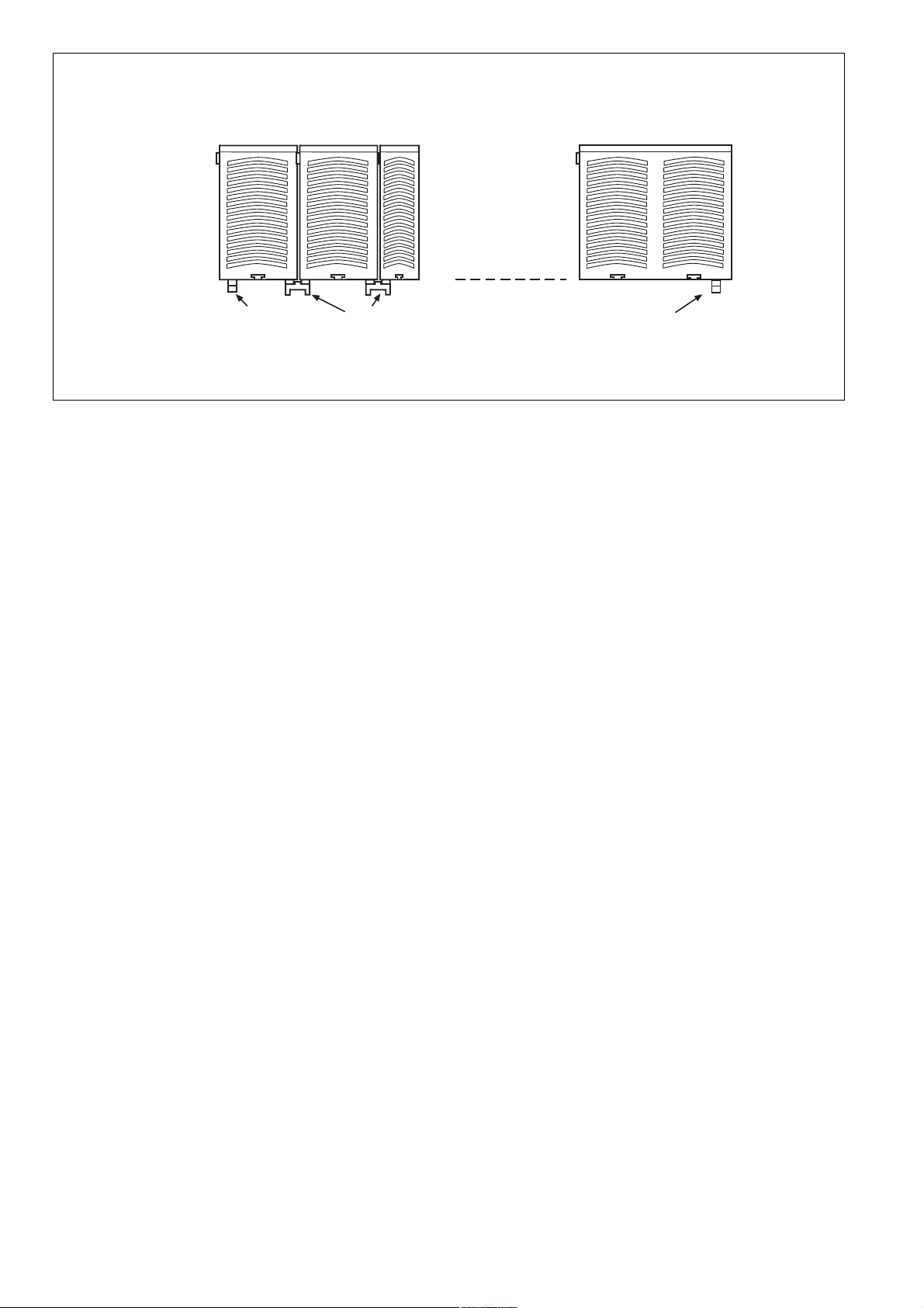
*Separación segura conforme a EN 60947-1, 6 kV/*Separazione sicura secondo EN 60947-1, 6 kV/*Veilige scheiding volgens EN 60947-1, 6 kV
PNOZ po3p
PNOZ po4p
Circuito de entrada
Circuiti di ingresso
Ingangscircuits
Circuito de realimentación
Circuito di retroazione
Terugkoppelcircuit
Circuito de entrada
Circuiti di ingresso
Ingangscircuits
Circuito de realimentación
Circuito di retroazione
Terugkoppelcircuit
Bus PNOZpower
PNOZpower-bus
Bus PNOZpower
PNOZpower-bus
Bus PNOZpower
PNOZpower-bus
13 23 33
K1
K2
14 24 34
13 23 33
K1
K2
*
41
42
*
43
Esquema interno
Bus PNOZpower
PNOZpower-bus
Schema connessioni Intern schema
14 24 34
- 9 -
44
Page 10

Descripción del funcionamiento
Modo de trabajo:
Los contactos de seguridad están
gobernados por el dispositivo básico. Los
circuitos de entrada, el circuito de
realimentación y la tensión de alimentación
van por el bus PNOZpower.
Cuando se conecta la tensión de
alimentación y los circuitos de entrada están
conectados al dispositivo básico, ambos relés
de salida K1 y K2 pasan a la posición de
funcionamiento.
• PNOZ po3p
Los contactos de seguridad 13-14, 23-24,
33-34 se cierran y el contacto auxiliar 4142 se abre. Si se abren los circuitos de
entrada, caen los relés K1 y K2. Los
contactos de seguridad con guiado
mecánico 13-14, 23-24 y 33-34 se abren y
el contacto auxiliar 41-42 se cierra.
• PNOZ po4p
Los contactos de seguridad 13-14, 23-24,
33-34 y 43-44 se cierran. Si se abren los
circuitos de entrada, caen los relés K1 y
K2. Los contactos de seguridad con
cuiado mecánico 13-14, 23-24 y 33-34 se
abren y el contacto auxiliar 41-42 se
cierra.
Descrizione del funzionamento
Modalità di lavoro:
I contatti di sicurezza sono controllati dal
dispositivo di base. Tensione di
alimentazione, circuiti d'ingresso e circuito di
retroazione sono gestiti mediante il Bus
PNOZpower.
Non appena la tensione di alimentazione è
disponibile ed i circuiti di ingresso sono
collegati al dispositivo di base, entrambi i relè
di uscita K1 e K2 passano in posizione di
lavoro.
• PNOZ po3p
I contatti di sicurezza 13-14, 23-24, 33-34
si chiudono e il contatto ausiliario 41-42 si
apre. Se i circuiti di ingresso si aprono, i
relè K1 e K2 si diseccitano. I contatti di
sicurezza forzati 13-14, 23-24, 33-34 si
aprono e il contatto ausiliario 41-42 si
chiude.
• PNOZ po4p
I contatti di sicurezza 13-14, 23-24, 33-34
e 43-44 si chiudono. Se i circuiti di
ingresso si aprono, i relè K1 e K2 si
diseccitano. I contatti di sicurezza forzati
13-14, 23-24, 33-34 si aprono e il contatto
ausiliario 41-42 si chiude.
Functiebeschrijving
Werking:
De veiligheidscontacten worden door het
basisrelais aangestuurd. Voedingsspanning,
ingangscircuits en terugkoppelcircuit worden
via de PNOZpower-bus uitgevoerd.
Zodra de voedingsspanning ingeschakeld is
en de ingangscircuits op het basisrelais
gesloten zijn, worden de beide uitgangsrelais
K1 en K2 bekrachtigd.
• PNOZ po3p
De veiligheidscontacten 13-14, 23-24, 3334 sluiten en het hulpcontact 41-42 gaat
open. Als de ingangscircuits worden
geopend, vallen de relais K1 en K2 af. De
mechanisch gedwongen veiligheidscontacten 13-14, 23-24, 33-34 gaan open
en het hulpcontact 41-42 sluit.
• PNOZ po4p
De veiligheidscontacten 13-14, 23-24, 3334 en 43-44 sluiten. Als de ingangscircuits
worden geopend, vallen de relais K1 en
K2 af. De mechanisch gedwongen
veiligheidscontacten 13-14, 23-24, 33-34
en 43-44 gaan open.
Montaje del dispositivo de seguridad
Atención: el dispositivo tiene que ser
montado dentro de un armario de
distribución con un grado de
protección IP54 como mínimo.
• Fije el dispositivo a una guía normalizada
con ayuda de los dos elementos de encaje
de la parte trasera.
• Monte el aparato en una guía normalizada
horizontal. Si lo monta en otra posición, no
se mantendrán los valores del poder de
corte indicados en las características
técnicas.
• El módulo de ampliación PNOZ po3p,
PNOZ po4p se puede montar en cualquier
lugar dentro del sistema de seguridad
modular PNOZpower.
• Hay 2 conectores hembra en la parte
posterior del dispositivo. El módulo de
ampliación PNOZ po3p, PNOZ po4p se
conecta a los otros aparatos del sistema
de seguridad modular PNOZpower
mediante los puentes insertables
suministrados con él.
Importante: hay que insertar un
terminador en el primer y en el último
dispositivo (véase la figura "Montaje
del PNOZ po3p, PNOZ po4p").
• Utilice exclusivamente terminadores del
sistema de seguridad modular
PNOZpower (marcados con el n.º de
referencia 95579).
• Número máximo de módulos admitidos
por un sistema PNOZpower:
- 1 dispositivo básico
- 4 módulos de ampliación
- 1 fuente de alimentación
Montaggio del modulo elettrico di
sicurezza
Attenzione! Il modulo di sicurezza
deve essere montato in un armadio
elettrico con un tipo di protezione
corrispondente almeno al grado IP 54.
• Fissare il dispositivo su una guida DIN con
l'aiuto dei due elementi a scatto situati sul
retro.
• Fissare il dispositivo su una guida
orizzontale. Nel caso di posizioni di
installazione diverse, i valori indicati nei
dati tecnici per il potere di interruzione non
possono essere rispettati.
• Il modulo di espansione PNOZ po3p,
PNOZ po4p può essere montato a
piacimento su qualisiasi punto del sistema
modulare di sicurezza PNOZpower.
• Sul retro del dispositivo sono alloggiate 2
boccole. Il modulo di espansione PNOZ
po3p o PNOZ po4p, viene collegato con
gli altri dispositivi del sistema di sicurezza
modulare PNOZpower mediante i ponticelli
forniti.
Importante: sul primo e sull’ultimo
dispositivo è necessario inserire un
connettore terminale (v. fig. "Montaggio
del PNOZ po3p, PNOZ po4p")!
• Utilizzare soltanto il connettore terminale
per il sistema di sicurezza modulare
PNOZpower (stampigliatura: n.95579).
• Dotazione massima di un sistema
PNOZpower:
- 1 apparecchio base
- 4 moduli di espansione
- 1 alimentatore di rete
Veiligheidsrelais monteren
Let op! Monteer het veiligheidsrelais
in een schakelkast met een beschermingsgraad van minimaal IP54.
• Bevestig het apparaat met behulp van de
twee relaisvoeten op de achterzijde op een
DIN-rail.
• Monteer het apparaat op een horizontale
draagrail. Bij andere inbouwposities kan
niet voldaan worden aan de waarden die
in de techn. gegevens voor het schakelvermogen zijn opgegeven.
• De uitbreidingsmodule PNOZ po3p,
PNOZ po4p kan op een willekeurige
plaats van het modulaire veiligheidssysteem PNOZpower gemonteerd worden.
• Op de achterzijde van het apparaat
bevinden er zich 2 busaansluitingen. De
uitbreidingsmodule PNOZ po3p,
PNOZ po4p wordt verbonden met de
andere apparaten van het modulaire
veiligheidssysteem PNOZpower via de
meegeleverde busconnectoren.
Belangrijk: op het eerste en laatste
apparaat moet er een afsluitconnector
geplaatst worden (zie fig. "Montage
van de PNOZ po3p, PNOZ po4p")!
• Alleen afsluitconnectoren voor het
modulaire veiligheidssysteem PNOZpower
gebruiken (voorzien van artikelnr. 95579).
• Maximale bezetting van een PNOZpowersysteem:
- 1 basisrelais
- 4 uitbreidingsmodulen
- 1 voedingsmodule
Puesta en marcha del dispositivo de
seguridad
Preparación de la puesta en marcha:
Al poner en marcha hay que tener en cuenta:
Atención: los bornes de conexión
insertables sólo se deben insertar o
extraer cuando se encuentren libres
de tensión.
Messa in funzione del modulo di
sicurezza
Preparazione della messa in funzione:
Informazioni preliminari:
Attenzione: innestare e staccare i
morsetti di collegamento inseribili
soltanto in assenza di tensione.
- 10 -
Veiligheidsrelaiselais in gebruik
nemen
Ingebruikneming voorbereiden:
Neem bij ingebruikneming het volgende in acht:
Let op: de steekbare aansluitklemmen alleen in de spanningsloze
toestand uittrekken en plaatsen.
Page 11

Fuente de
alimentación
Alimentatore
di rete
Voedingsmodule
Dispositivo
básico
Dispositivo
di base
Basisrelais
Módulo de ampliación 1
Module di espansione 1
Uitbreidingsmodule 1
PNOZ po3p
PNOZ po4p
Módulo de ampliación 4
Module di espansione 4
Uitbreidingsmodule 4
95579
Terminador
Connettore terminale
Afsluitconnector
Montaje del PNOZ po3p, PNOZ po4p
• Se debe poner en el circuito un fusible
antes de los contactos de salida
(véanse las características técnicas),
para evitar que los contactos puedan
quedar soldados.
• No se deben conmutar corrientes
pequeñas (p.ej. 30 mA) con contactos que
se hayan utilizado anteriormente con
corrientes fuertes.
• Utilizar material de alambre de cobre con
una resistencia a la temperatura de
60/75 °C para las líneas.
• El par de apriete de los tornillos de los
bornes de conexión debe ser 0,5 Nm.
• Respetar sin falta las indicaciones del
capítulo "Datos técnicos".
Funcionamiento
El dispositivo se encuentra listo para el
funcionamiento cuando
• recibe tensión por el bus PNOZpower (LED
"POWER" encendido),
• los circuitos de entrada en el dispositivo
básico están cerrados.
Indicaciones de estado:
• Los LEDs "K1" y "K2" se encienden:
- PNOZ po3p:
Los contactos de seguridad 13-14, 2324 y 33-34 están cerrados y el contacto
auxiliar 41-42 está abierto.
- PNOZ po4p:
Los contactos de seguridad 13-14, 2324, 33-34 y 43-44 están cerrados.
• Los LEDs "K1" y "K2" se apagan:
- PNOZ po3p:
Los contactos de seguridad 13-14, 2324 y 33-34 están abiertos, el contacto
auxiliar 41-42 está cerrado.
- PNOZ po4p:
Los contactos de seguridad 13-14, 2324, 33-34 y 43-44 están abiertos.
Indicación de fallos:
• El LED "FAULT" se ilumina: fallo de los
contactos
95425
Puentes insertables
Ponticello
Busconnector
Montaggio del PNOZ po3p, PNOZ po4p Montage van de PNOZ po3p, PNOZ po4p
• Per evitare la saldatura dei contatti,
collegare un fusibile (vedi dati tecnici) a
monte dei contatti di uscita.
• Non commutare piccole correnti (p. es. 30
mA) con contatti attraverso i quali sono
state commutate in precedenza alte
correnti.
• Per i cavi utilizzare materiale in filo di rame
con una resistenza termica intorno ai
60/75 °C.
• La coppia di serraggio massima delle viti
sui morsetti deve essere di 0,5 Nm.
• Attenersi assolutamente alle indicazioni
riportate al capitolo "Dati tecnici".
Funzionamento
Il dispositivo è pronto per il funzionamento
quando:
• è presente la tensione di alimentazione
tramite il Bus PNOZpower (LED "POWER"
acceso),
• i circuiti di entrata sul dispositivo di base
sono chiusi.
Visualizzazioni di stato
• I LED "K1" e "K2" lampeggiano:
- PNOZ po3p:
I contatti di sicurezza 13-14, 23-24, 3334 sono chiusi, il contatto ausiliario 4142 è aperto.
- PNOZ po4p:
I contatti di sicurezza 13-14, 23-24, 3334 e 43-44 sono chiusi.
• I LED "K1" e "K2" si spengono:
- PNOZ po3p:
I contatti di sicurezza 13-14, 23-24, 3334 sono aperti, il contatto ausiliario 4142 è chiuso.
- PNOZ po4p:
I contatti di sicurezza 13-14, 23-24, 3334 e 43-44 sono aperti.
Visualizzazioni di errore:
• Il LED "FAULT" è acceso:
malfunzionamento dei contatti
95579
Terminador
Connettore terminale
Afsluitconnector
• Uitgangscontacten afzekeren (zie
technische gegeven) om het verkleven
van de contacten te voorkomen.
• Geen geringe stroomsterkten (b.v. 30 mA)
via contacten schakelen die tevoren grote
stroomsterkten verwerkt hebben.
• Kabelmateriaal van koperdraad met een
temperatuurbestendigheid van 60/75 °C
gebruiken.
• Het aanhaalmoment van de schroeven op
de aansluitklemmen moet 0,5 Nm
bedragen.
• Aanwijzingen in het hoofdstuk "Technische
gegevens" beslist opvolgen.
Bedrijf
Het apparaat is bedrijfsklaar als
• de voedingsspanning via de PNOZpowerbus ingeschakeld is (LED "POWER" licht
op),
• de ingangscircuits op het basisrelais
gesloten zijn.
Statusweergave:
• LEDs "K1" en "K2" lichten op:
- PNOZ po3p:
Veiligheidscontacten 13-14, 23-24 en
33-34 zijn gesloten, hulpcontact 41-42 is
geopend.
- PNOZ po4p:
Veiligheidscontacten 13-14, 23-24, 3334 en 43-44 zijn gesloten.
• LEDs "K1" en "K2" doven:
- PNOZ po3p:
Veiligheidscontacten 13-14, 23-24 en
33-34 zijn geopend, hulpcontact 41-42
is gesloten.
- PNOZ po4p:
Veiligheidscontacten 13-14, 23-24, 3334 en 43-44 zijn geopend.
Foutweergave:
• LED "FAULT" licht op: contactfout
- 11 -
Page 12

Errores - Fallos
Se puede comprobar cerrando o abriendo
los circuitos de entrada en el dispositivo
básico, si el PNOZ po3p, PNOZ po4p se
conecta o desconecta correctamente.
Por motivos de seguridad, el dispositivo no
se puede arrancar cuando se presentan los
fallos siguientes:
• Fallo de los contactos (el LED "FAULT" se
enciende): Como el PNOZ po3p, PNOZ po4p
está conectado a un dispositivo básico, no se
puede volver a poner en funcionamiento
después de haber abierto el circuito de
entrada, si los contactos están soldados.
• Interrupción de línea, cortocircuito o contacto
a tierra (p.ej. en el circuito de entrada del
dispositivo básico)
Errori - Guasti
Chiudendo o interrompendo i circuiti
d’ingresso sul dispositivo di base, è possibile
verificare se PNOZ po3p, PNOZ po4p si
accendono e spengono correttamente.
Per ragioni di sicurezza il dispositivo non può
essere attivato in presenza delle seguenti
anomalie:
• Malfunzionamento dei contatti (il LED
"FAULT" lampeggia):
PNOZ po4p viene cablato con un dispositivo di
base, in caso di saldatura dei contatti, dopo
l’apertura del circuito di ingresso non è più
possibile effettuare nessuna nuova attivazione.
• Interruzione di linea, cortocircuito o
dispersione a terra (p. es. nel circuito di
ingresso del dispositivo di base)
Poichè il PNOZ po3p,
Fouten - Storingen
Door het sluiten of onderbreken van de
ingangscircuits op het basisrelais kan
gecontroleerd worden, of de PNOZ po3p,
PNOZ po4p correct in- of uitschakelt.
Het apparaat kan om veiligheidsredenen bij
de volgende fouten niet gestart worden:
• Contactfout (LED "FAULT" licht op):
Omdat PNOZ po3p, PNOZ po4p op een
basisrelais aangesloten is, is er bij verkleefde
contacten na het openen van het
ingangscircuit geen nieuwe activering
mogelijk.
• Kabelbreuk, kort- of aardsluiting (b.v. in het
ingangscircuit van het basisrelais)
Datos técnicos
Alimentación
Tolerancia de tensión de alimentación U
Consumo de energía con U
Contactos de salida según
EN 954-1, EN ISO 13849-1 categoría 4
PNOZ po3p:
contactos de seguridad (NA)
contactos auxiliares (NC)
PNOZ po4p:
contactos de seguridad (NA)
Material de los contactos
Categóría de uso según
EN 60947-4-1
EN 60947-5-1
DC13: 6 ciclos/min.
Protección externa de los contactos
Fusible
- rápido
- lento
característica B/C
Vida útil mecánica
ciclos
Retardo a la conexión (sin dispositivo
básico)
Retardo a la caída (sin dispositivo
básico)
Distancias de fuga por aire y
superficial según EN 60947-1
Grado de suciedad
Tensión de aislamiento de dimensionado
Resistencia tensión transitoria de
dimensionado
Condiciones climáticas
CEM
Vibraciones según
Frecuencia
Amplitud
Temperatura ambiente
Temperatura de almacenaje
Grado de protección
Lugar de montaje (p.ej. armario de
distribución)
Carcasa
Zona de bornes
Sección del cable exterior
1 conductor flexible
2 conductores de la misma sección
flexibles con terminal sin
sin revestimiento de plástico
flexible sin terminal o
con terminal TWIN
B
Dati tecnici
Tensione di alimentazione
Tolleranza di tensione U
B
Potenza assorbita con U
Contatti di uscita conformi alla norma
EN 954-1, EN ISO 13849-1 categoria 4
PNOZ po3p:
Contatti di sicurezza (NA)
Contatti ausiliari (NC)
PNOZ po4p:
Contatti di sicurezza (NA)
Materiale contatti
Categoria d’uso secondo
EN 60947-4-1
EN 60947-5-1
DC13: 6 cicli di commutazione/min.
Fusibile dei contatti esterni
Fusibile
- rapido
- ritardato
caratteristica del tipo B/C
Durata meccanica
Cicli
Ritardo all’eccitazione (senza
dispositivo di base)
Ritardo alla diseccitazione (senza
dispositivo di base)
Caratteristiche dielettriche secondo
EN 60947-1
Grado di contaminazione
Tensione nominale di isolamento
Tensione di tenuta agli urti
Sollecitazione climatica
CEM
Oscillazioni secondo norma
Frequenza
Ampiezza
Temperatura ambiente
Temperatura di immagazzinamento
Tipo di protezione
Spazio di montaggio (p.es. quadro
elettrico ad armadio)
Custodia
Terminali
Sezione del conduttore esterno
1 conduttore flessibile
2 conduttori con lo stesso diametro
flessibile con capocorda senza
manicotto in plastica
flessibile senza capocorda oppure
con capocorda TWIN
B
B
Technische gegevens
Voedingsspanning
Spanningstolerantie U
Opgenomen vermogen bij U
Uitgangscontacten volgens EN 954-1,
EN ISO 13849-1 categorie 4
PNOZ po3p:
Veiligheidscontacten (M)
Hulpcontacten (V)
PNOZ po4p:
Veiligheidscontacten (M)
Contactmateriaal
Gebruikscategorie volgens
EN 60947-4-1
EN 60947-5-1
DC13: 6 schakelingen/min.
Contactafzekering extern
Smeltzekering
- snel
- traag
karakteristiek B/C
Mechanische levensduur
Schakelingen
Inschakelvertraging (zonder
basisrelais)
Afvalvertraging
(zonder basisrelais)
Lucht- en kruipwegen volgens
EN 60947-1
Vervuilingsgraad
Nominale isolatiespanning
Nominale
stootspanningbestendigheid
Klimaatcondities
EMC
Trillingsbestendigheid volgens
Frequentie
Amplitude
Omgevingstemperatuur
Opslagtemperatuur
Beschermingsgraad
Inbouwruimte (b.v. schakelkast)
Behuizing
Aansluitklemmen
Doorsnede van de aansluitkabels
1 draad flexibel
2 draden met dezelfde doorsnede
Flexibel met adereindhuls zonder
kunststofhuls
Flexibel zonder adereindhuls of
met TWIN-adereindhuls
B
B
por el bus PNOZpower/
tramite Bus PNOZpower/
via PNOZpower-bus
-15 % / +10 %
2 W
3
1
4
AgSnO2 + 0,2 μm Au
AC1: 240 V/0,03 ... 4 A/960 VA
DC1: 24 V/4 A/96 W
AC15: 240 V/4 A
DC13: 24 V/4 A
6 A
4 A
24 V AC/DC: 4 A
7
1 x 10
typ. 22 ms,
max. 35 ms
typ. 18 ms,
max. 30 ms
2
250 V
6 kV
EN 60068-2-78
EN 60947-5-1, EN 61000-6-2,
EN 61000-6-3
EN 60068-2-6
10 ... 55 Hz
0,35 mm
-10 ... +55 °C
-40 ... +85 °C
IP54
IP30
IP20
0,25 ... 2,5 mm2, 24 - 1 2 AWG
0,25 ... 1 mm2, 24 - 1 6 AWG
0,20 ... 2,5 mm2, 24 - 1 6 AWG
- 12 -
Page 13

Par de apriete para
bornes de conexión (tornillos)
Material de la carcasa
Frontal
Caja
Posición de montaje
Dimensiones A x A x L
Peso
Coppia per
morsetti (viti)
Materiale usato per la custodia
Fronte
Custodia
Posizione di montaggio
Dimensioni: altezza x larghezza x
profondità
Peso
Aanhaalmoment voor
aansluitklemmen (schroeven)
Behuizingsmateriaal
Front
Behuizing
Inbouwpositie
Afmetingen h x b x d
Gewicht
0,50 Nm
ABS UL 94 V0
PPO UL 94 V0
horizontal/orizzontale/
horizontaal
94 x 22,5 x 121 mm
230 g
Son válidas las versiones actuales de las
normas 2008-06.
Declaración CE de conformidad:
Estos productos cumplen los requisitos de la
Directiva de Máquinas 2006/42/CE del
Parlamento Europeo y del Consejo.
La declaración CE de conformidad completa
pueden encontrarla en la página web de
Internet www.pilz.com
Apoderado: Norbert Fröhlich,
Pilz GmbH & Co. KG, Felix-Wankel-Str. 2,
73760 Ostfildern, Deutschland
Per le norme citate, sono applicate le
versioni in vigore a 2008-06.
Dichiarazione di conformità CE:
Questo(i) prodotto(i) soddisfa i requisiti della
Direttiva 2006/42/CE del Parlamento e del
Consiglio Europeo sulle macchine.
Il testo integrale della Dichiarazione di
conformità CE è disponibile in Internet
all’indirizzo www.pilz.com
Mandatario: Norbert Fröhlich,
Pilz GmbH & Co. KG, Felix-Wankel-Str. 2,
73760 Ostfildern, Germania
Van toepassing zijn de in 2008-06 actuele
versies van de normen.
EG-conformiteitsverklaring:
Deze produkten voldoen aan de eisen van de
Europese Machinerichtlijn 2006/42/EG.
De volledige EG-conformiteitsverklaring vindt
u op wwww.pilz.com
Gevolmachtige: Norbert Fröhlich,
Pilz GmbH & Co. KG, Felix-Wankel-Str. 2,
73760 Ostfildern, Duitsland
- 13 -
Page 14

D
Lebensdauer der Ausgangsrelais
GB
FService Life of Output relays Durée de vie des relais de
sortie
E
D
E
Vida útil de los relés de salida
10
DC13: 24 V
1
D Nennbetriebstrom (A)
GB Nominal operating current (A)
F Courant coupé (A)
0.1
E Corriente nominal de servicio (A)
I Corrente di esercizio nominale (A)
NL Nominale bedrijfsstroom (A)
10 100 1000 10000
D Schaltspielzahl x 10
GB Cycles x 10
F Nombre de manvres x 10
Anschlussbeispiel:
Anschlussbeispiel für höhere
Kontaktströme.
Ejemplo de conexión:
Ejemplo de conexión para corrientes
de contacto fuertes.
I
GB
I
Durata dei relè di uscita
AC1: 230 V
3
3
E Número de ciclos x 10
I Numero dei cicli di commutazione x 10
3
NL Aantal schakelingen x 10
Connection example:
A connection example for higher
0contact currents.
Esempio di collegamento:
Esempio di collegamento per
correnti di contatto maggiori.
AC15: 230 V
NL
Levensduur van de uitgangsrelais
DC1: 24 V
F
NL
Exemple de raccordement :
Exemple de raccordement pour les
courants de contact de forte intensité
Aansluitvoorbeeld:
Aansluitvoorbeeld van hogere
contactstromen.
3
3
3
D
E
1L1
K5
K4
Y1 Y2
K4 K5
1L2
Dimensiones en mm (")
13
14
PNOZ po3p
PNOZ po4pPNOZ p1p
GB
I
Dimensions in mm (")Abmessungen in mm (")
Dimensioni in mm (")
F
NL
Dimensions en mm (")
Afmetingen in mm (")
94 (3.70")
121 (4.76")
135 (5.31")
- 14 -
22,5
(0.88")
Page 15

D
E
Anschlussbelegung Connector pin assignment
Asignación de conexiones
GB Affectation des raccords
I
Schema di collegamento Klembezetting
F
NL
PNOZ po3p
PNOZ po4p
- 15 -
Page 16

Asistencia técnica
+49 711 3409-444 +49 711 3409-444
...
Estamos representados en
muchos países por nuestros
socios comerciales.
Obtendrá más información a
través de nuestra Homepage
o entrando en contacto con
nuestra casa matriz.
Supporto tecnico
... ...
In molti Paesi siamo rappresentati
da partner commerciali.
Per maggiori informazioni potete
contattarci direttamente o tramite
la nostra Homepage.
Technische Support
+49 711 3409-444
In veel landen zijn wij
vertegenwoordigd door
handelspartners.
Voor meer informatie kunt
u onze homepage raadplegen
of contact opnemen met
ons hoofdkantoor.
- 16 -
www
www.pilz.com
Pilz GmbH & Co. KG
Felix-Wankel-Straße 2
73760 Ostfildern, Germany
Telephone: +49 711 3409-0
Telefax: +49 711 3409-133
E-Mail: pilz.gmbh@pilz.de
Manual de Instrucciones original/Istruzioni originali/Originele bedrijfshandleiding
20 772-04-2010-08 Printed in Germany
 Loading...