

Page 1

20674-6NL-04
PNOZ p1p
4
D Betriebsanleitung
4
GB Operating instructions
4
F Manuel d'utilisation
4 E Instrucciones de uso
4 I Istruzioni per l`uso
4 NL Gebruiksaanwijzing
Sicherheitsbestimmungen
• Das Gerät darf nur von Personen installiert
und in Betrieb genommen werden, die mit
dieser Betriebsanleitung und den geltenden Vorschriften über Arbeitssicherheit
und Unfallverhütung vertraut sind.
Beachten Sie die VDE- sowie die örtlichen
Vorschriften, insbesondere hinsichtlich
Schutzmaßnahmen.
• Beim Transport, der Lagerung und im
Betrieb die Bedingungen nach EN 600682-6 einhalten (s. technische Daten).
• Durch Öffnen des Gehäuses oder eigenmächtige Umbauten erlischt jegliche Gewährleistung.
• Montieren Sie das Gerät in einen Schaltschrank; Staub und Feuchtigkeit können
sonst zu Beeinträchtigungen der Funktionen führen.
Bestimmungsgemäße Verwendung
Das Basisgerät PNOZ p1p für das modulare
Sicherheitssystem PNOZpower ist bestimmt
für den Einsatz in
• Not-Halt-Einrichtungen
• Sicherheitsstromkreisen nach EN 60204-1
(VDE 0113-1) und IEC 60204-1 (z. B. bei
beweglichen Verdeckungen)
Gerätebeschreibung
Das Basisgerät PNOZ p1p ist in einem P-01Gehäuse untergebracht. Die Versorgungsspannung beträgt 24 V DC.
Merkmale:
• Anschlussmöglichkeit für Not-Halt-Taster,
Schutztürgrenztaster und Starttaster
• Statusanzeige für Schaltzustand von
Eingangs- und Ausgangskreisen, Startkreis, Versorgungsspannung und Störung
• Rückführkreis zur Überwachung externer
Schütze
• 2 Halbleiterausgänge melden Betriebsbereitschaft bzw. Störung
(Sammelstörmeldung für PNOZ p1p und
den Erweiterungsmodulen bei Erd- oder
Querschluss)
• Ausgang zur Ansteuerung der
Erweiterungsmodule auf PNOZpower-Bus
geführt
• max. 4 Erweiterungsmodule anschließbar
• Verbindung zwischen dem PNOZ p1p und
den Erweiterungsmodulen über
PNOZpower-Bus durch Steckbrücke auf
der Geräterückseite
Das Schaltgerät erfüllt folgende Sicherheitsanforderungen:
• Schaltung ist redundant mit Selbstüberwachung aufgebaut (EN 954-1, Kategorie 4).
• Sicherheitseinrichtung bleibt auch bei
Ausfall eines Bauteils wirksam.
• Bei jedem Ein-Aus-Zyklus der Maschine
wird automatisch überprüft, ob die Relais
der Sicherheitseinrichtung richtig öffnen
und schließen.
Safety Regulations
• The unit may only be installed and
operated by personnel who are familiar
with both these instructions and the current
regulations for safety at work and accident
prevention. Follow VDE and local
regulations especially as regards
preventative measures.
• Transport, storage and operating
conditions should all conform to EN 600682-6.
• Any guarantee is void following opening of
the housing or unauthorised modifications.
• The unit should be panel mounted,
otherwise dampness or dust could lead to
function impairment.
Authorised Applications
The PNOZ p1p base unit for the PNOZpower
modular safety system is intended for use in
• Emergency Stop circuits.
• Safety Circuits according to EN 60204-1
(VDE 0113-1) and IEC 60204-1 (e.g. with
movable guards).
Unit Description
The PNOZ p1p base unit is fitted in a P-01
housing. Supply voltage is 24 VDC.
Features:
• E-STOP, safety gate and start buttons
connection options
• Input, output and start circuits, power
supply and fault status display
• Feedback loop for monitoring external
contactors
• 2 semiconductor outputs signal operational readiness or a fault (collective fault
message for PNOZ p1p and expander
modules for earthing or short circuits)
• Expander module control output fed at the
PNOZpower bus
• You can connect a maximum of 4
expander modules
• Connection between the PNOZ p1p and
expander modules via the PNOZpower
bus, employing jumpers on the rear face of
the unit.
The relay conforms to the following safety
requirements:
• The circuit is redundant, with built-in selfmonitoring (EN 954-1, Category 4).
• The safety function remains effective in the
case of a component failure.
• The correct opening and closing of the
safety function relays is tested automatically in each on-off cycle.
Conseils préliminaires
• La mise en oeuvre de l’appareil doit être
effectuée par une personne spécialisée en
installations électriques, en tenant compte
des prescriptions des différentes normes
applicables (NF, EN, VDE...) notamment
au niveau des risques encourus en cas de
défaillance de l’équipement électrique.
• Respecter les exigences de la norme
EN 60068-2-6 lors du transport, du
stockage et de l'utilisation de l'appareil.
• L’ouverture de l’appareil ou sa modification
annule automatiquement la garantie.
• L’appareil doit être monté dans une armoire; l’humidité et la poussière pouvant
entraîner des aléas de fonctionnement.
Domaines d’utilisation
L’appareil de base PNOZ p1p est logé dans
un boîtier P01. Sa tension d’alimentation est
de 24 V DC.
• les circuits d’arrêt d’urgence
• les circuits de sécurité selon les normes
EN 60204-1 (VDE 0113-1) et IEC 60204-1
(ex. protecteurs mobiles).
Description de l’appareil
L’appareil de base PNOZ p1p est logé dans
un boîtier P01. Sa tension d’alimentation est
de 24 V DC.
Caractéristiques :
• Raccordements possibles : poussoir d’AU,
interrupteur de position et poussoir de
réarmement
• Visualisation de l’état de commutation des
circuits d’entrée et de sortie, du circuit de
réarmement, de la tension d’alimentation et
des défauts
• Boucle de retour pour contrôler les relais
externes
• 2 sorties statiques pour signaler que
l’appareil est prêt à fonctionner ou en
dérangement (message d’erreur groupé
pour le PNOZ p1p et les modules
d’extension en cas de mise à la terre ou de
court-circuit)
• Sortie de commande des modules
d’extension via le bus PNOZpower
• Possibilité de raccorder jusqu’à 4 modules
d’extension maximum
• Liaison entre le PNOZ p1p et les modules
d’extension via le bus PNOZpower au
moyen de cavaliers de pontage situés sur
la face arrière de l’appareil
Le relais satisfait aux exigences de sécurité
suivantes :
• Commutation redondante avec
autosurveillance (EN 954-1, catégorie 4).
• Le dispositif de sécurité reste actif, même
en cas de défaillance d’un composant.
• L’ouverture et la fermeture correctes des
relais du dispositif de sécurité sont
contrôlées automatiquement à chaque
cycle marche/arrêt de la machine.
- 1 -
Page 2
Funktionsbeschreibung
Das Basisgerät PNOZ p1p dient zusammen
mit den Erweiterungsmodulen dem sicherheitsgerichteten Unterbrechen eines
Sicherheitsstromkreises.
Das Gerät ist betriebsbereit, wenn
• die Versorgungsspannung anliegt
• die Betriebsart festgelegt wurde
• der Rückführkreis geschlossen ist
• die Startbedingung gewählt wurde
Die LED "POWER" leuchtet.
• Eingangskreis geschlossen (z. B. Not-HaltTaster nicht betätigt):
Die Statusanzeigen für "CH.1 IN" und
"CH.2 IN" leuchten. Das Ausgangssignal
auf dem PNOZpower-Bus zur Ansteuerung
der Erweiterungsmodule wird gesetzt. Die
Statusanzeige "OUT" leuchtet.
• Eingangskreis wird geöffnet (z. B. NotHalt-Taster betätigt):
Die Statusanzeige für "CH.1 IN" und
"CH.2 IN" erlischt. Das Ausgangssignal auf
dem PNOZpower-Bus zur Ansteuerung
der Erweiterungsmodule wird zurückgesetzt. Die Statusanzeige "OUT" erlischt.
Halbleiterausgänge
Der Halbleiterausgang Y35 leitet, wenn die
Versorgungssspannung anliegt und die
interne Sicherung nicht ausgelöst hat. Er
sperrt bei Störung des Basisgeräts
PNOZ p1p oder eines der Erweiterungsmodule.
Der Halbleiterausgang Y32 leitet, wenn die
Relais K1 und K2 in Wirkstellung sind. Er
sperrt, wenn die Relais in Ruhestellung sind.
Function Description
The PNOZ p1p base unit and its expander
modules provide safety-related cut-out of a
safety circuit.
The unit is ready for operation when:
• supply voltage is present
• the orerating mode has been specified
• the feedback control loop is closed
• the start condition has been selected
The “POWER” LED illuminates.
• Input circuit closed (e.g. E-STOP button
not operated):
The “CH.1 IN” and “CH.2 IN” displays
illuminate. The output signal on the
PNOZpower bus is set for controlling the
expander modules. The “OUT” status
display will illuminate.
• The input circuit is opened (e.g. E-STOP
button operated):
The “CH.1 IN” and “CH.2 IN” status
display will go out. The output signal on
the PNOZpower bus is reset for controlling
the expander modules. The “OUT” status
display will go out.
Semiconductor outputs
Semiconductor output will be enabled if the
supply voltage is present and the internal
fuse has not blown. It is disabled if either the
PNOZ p1p base unit or any of the output
modules is faulty.
The semiconductor output Y32 is enabled if
relays K1 and K2 are energised. It is disabled
when the relays are de-energised.
Description du fonctionnement
Utilisé avec les modules d’extension,
l’appareil de base PNOZ p1p sert à
interrompre de manière sûre un circuit de
sécurité.
Le bloc logique est prêt à fonctionner lorsque
• La tension d’alimentation est raccordée
• la modes de fonctionnement est
sélectionnée
• la boucle de retour est fermée ;
• la condition de réarmement a été
sélectionnée
La diode "POWER" s’allume.
• Le circuit d’entrée est ouvert (par ex.
poussoir d’AU actionné) :
les LEDs de visualisation “CH.1 IN” et
“CH.2 IN” s’éteignent. Le signal de sortie
sur le bus PNOZpower pour la commande
des modules d’extension est annulé. La
LED de visualisation “OUT” s’éteint.
• Le circuit d’entrée est ouvert (par ex.
poussoir d’AU actionné) :
les LEDs de visualisation “CH.1 IN” et
“CH.2 IN” s’éteignent. Le signal de sortie
sur le bus PNOZpower pour la commande
des modules d’extension est annulé. La
LED de visualisation “OUT” s’éteint.
Sorties statiques
La sortie statique Y35 est conductrice
lorsque la tension d’alimentation est
appliquée et que le coupe-circuit interne ne
s’est pas déclenché. Elle est bloquée en cas
de dysfonctionnement de l’appareil de base
PNOZ p1p ou de l’un des modules
d’extension.
La sortie statique Y32 est conductrice
lorsque les relais K1 et K2 sont en position
de travail et bloquée lorsqu’ils sont au repos.
A2 (0V)
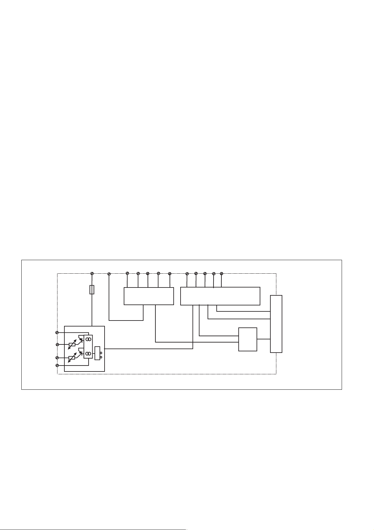
Eingangskreise
circuit d'entree
Y31
Y35
&
Y32
Y30
S21 Y1S34
Input circuit
Fig. 1: Innenschaltbild/Internal Wiring Diagram/Schéma de principe
Betriebsarten:
•
Einkanaliger Betrieb: EN 60204-1
(VDE 0113-1) und IEC 60204-1, keine
Redundanz im Eingangskreis, Erdschlüsse
im Tasterkreis werden erkannt.
• Zweikanaliger Betrieb: redundanter Eingangskreis, Erdschlüsse im Tasterkreis
und Querschlüsse zwischen den Tasterkontakten werden erkannt.
• Automatischer Start: Gerät ist aktiv, sobald
Eingangskreis geschlossen ist.
• Manueller Start: Gerät ist erst dann aktiv,
wenn ein Starttaster betätigt wird. Dadurch
ist ein automatischer Start des Schaltgeräts nach Spannungsausfall und wiederkehr ausgeschlossen.
Operating modes:
• Single-channel operation: Input wiring
according to
and IEC 60204-1
input circuit. Earth faults are detected in
the emergency stop circuit.
• Two-channel operation: Redundancy in the
input circuit. Earth faults in the Emergency
Stop circuit and shorts across the emergency
stop push button are also detected.
• Automatic reset: Unit is active as soon as
the input circuit is closed.
• Manual reset: Unit is only active when a
reset button has been pressed.
Automatic activation following a loss/return
of supply voltage is thereby prevented.
Y2S33S22S12 S52S11A1 (+)
S37
Start-/Rückführkreis
Reset circuit/feedback control loop
circuit de réarmement/boucle de retour
EN 60204-1 (VDE 0113-1)
, no redundancy in the
Sortie
Output
Ausgang
PNOZpower-Bus
Modes de fonctionnement :
• Commande par 1 canal : conforme aux
prescriptions de la
1) et IEC 60204-1
EN 60204-1 (VDE 0113-
, pas de redondance dans
le circuit d’entrée. La mise à la terre du
circuit d’entrée est détectée
• Commande par 2 canaux: circuit d’entrée
redondant. La mise à la terre et les courtscircuits entre les contacts sont détectées.
• Réarmement automatique : le relais est
activé dès la fermeture des canaux d’entrée.
• Réarmement manuel : le relais n’est activé
qu’après une impulsion sur un poussoir de
validation. Un réarmement automatique du
relais après une coupure d’alimentation est
ainsi impossible.
- 2 -
Page 3
• Manueller Start mit Überwachung: Gerät
ist erst aktiv, wenn der Starttaster betätigt
und wieder losgelassen wurde.
• Manual reset with monitoring: Unit is only
activated, when the reset button ist
pressed and then released.
• Surveillance de circuit de réarmement : le
relais n'est activé qu'après le relâchement
du poussoir de validation.
Montage
• Das Sicherheitsschaltgerät muss in einen
Schaltschrank (min. IP54) eingebaut
werden. Zur Befestigung auf einer
Tragschiene dienen zwei Rastelemente
auf der Rückseite des Geräts.
•
Montieren Sie das Gerät auf eine waagrechte Tragschiene. Bei anderen Einbaulagen können die in den techn. Daten
angegebenen Werte für das Schaltvermögen nicht eingehalten werden.
• Das Basisgerät PNOZ p1p kann an
beliebiger Stelle des modularen Sicherheitssystems PNOZpower montiert
werden.
• Auf der Geräterückseite des PNOZ p1p
befinden sich 2 Buchsen. Das Basisgerät
PNOZ p1p wird mit den Erweiterungsmodulen über die mitgelieferten Steckbrücken verbunden.
Beachten Sie: Auf das erste und letzte
Gerät muss ein Abschlussstecker
gesteckt werden (siehe Fig. 2)!
• Nur Abschlussstecker für das modulare
Sicherheitssystem PNOZpower verwenden
(Aufdruck: Sach-Nr. 95579).
• Maximalbestückung eines PNOZpowerSystems:
- 1 Basisgerät
- 4 Erweiterungsmodule
- 1 Netzgerät
Installation
• The safety relay must be installed in a
control cabinet (min. IP54). There are two
notches on the back of the unit for DIN rail
attachment.
• Fit the unit to a horizontal DIN rail. In other
mounting positions, the values given in the
technical details for the switching capability
may not be achieved.
• The PNOZ plp base unit can be installed in
any position on the PNOZpower modular
safety system.
• There are 2 sockets on the rear of the
PNOZ p1p. Connect the PNOZ p1p base
unit to the expander modules using the
jumpers supplied.
Please note: Be sure to plug a terminator in to the first and last units
(see Fig. 2)!
• Only use terminators for the PNOZpower
modular safety system (Catalogue: Item
No. 95579).
• Maximum hardware in a PNOZpower
system:
- 1 base unit
- 4 expander modules
- 1 power supply unit
Montage
• Le relais de sécurité doit être monté dans
une armoire avec, au minimum, l’indice de
protection IP54. Sa face arrière, dotée de
2 ergots, peut s’encliqueter sur un profilé
support.
• Montez l’appareil sur un profilé support
horizontal. Les autres positions de
montage ne permettent pas de respecter
les valeurs de commutation indiquées
dans les caractéristiques techniques.
•
L’appareil de base PNOZ p1p peut être
installé en n’importe quel point du système
de sécurité modulaire PNOZpower.
• La face arrière du PNOZ p1p comporte 2
douilles. L’appareil de base PNOZ p1p est
relié aux modules d’extension par le biais
des cavaliers de pontage fournis.
Important : le premier et le dernier
appareil doivent être pourvus d’une
fiche de terminaison (voir fig. 2) !
• Utilisez uniquement les fiches de
terminaison prévues pour le système de
sécurité modulaire PNOZpower
(Référence : 95579).
• Équipement maximal d’un système
PNOZpower :
- 1 appareil de base
- 4 modules d’extension
- 1 bloc d’alimentation
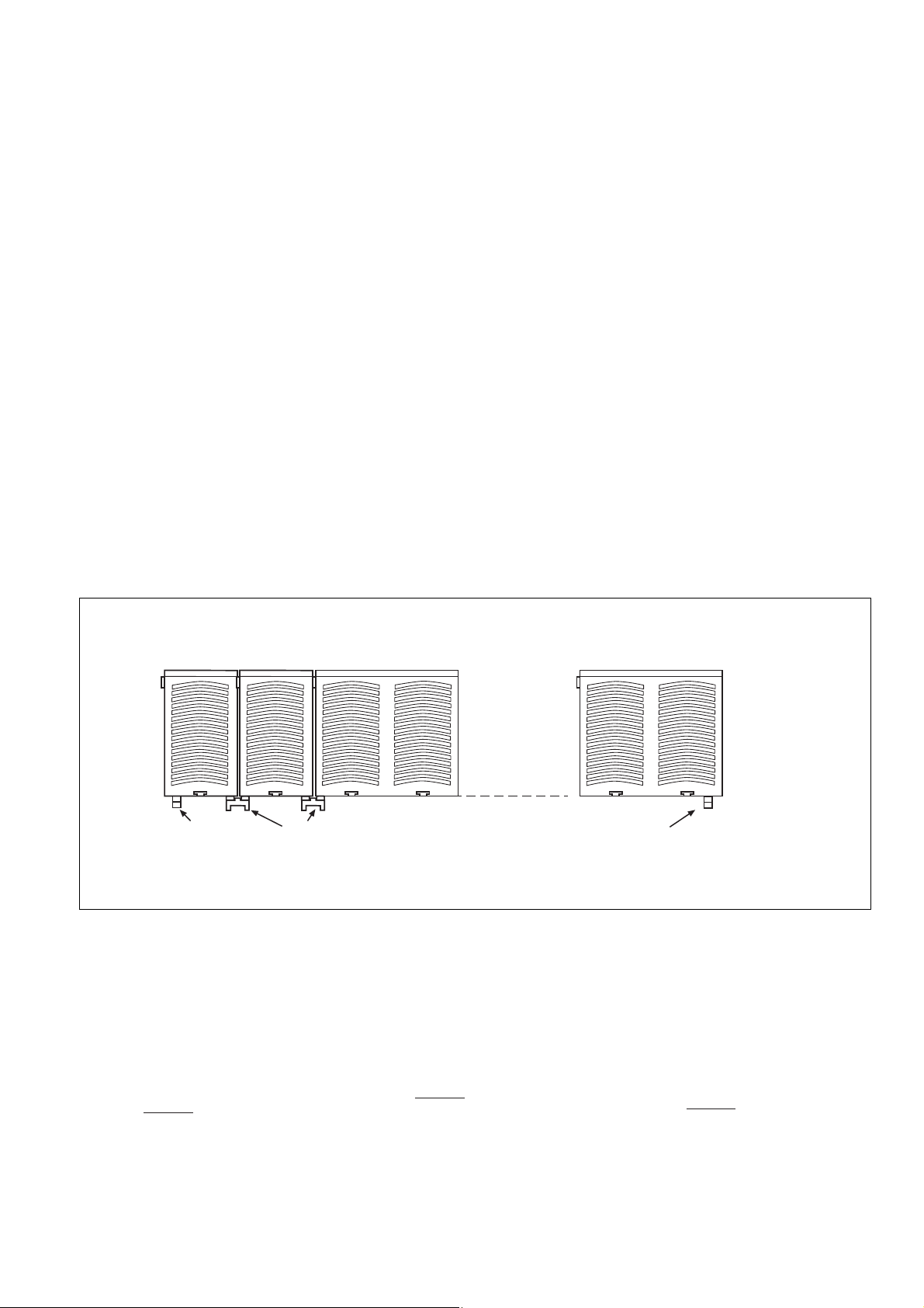
Netzgerät
Power Supply
Bloc
d'alimentation
95579
Abschlussstecker
Terminator
Fiche de
terminaison
Basisgerät
Base Unit
Appareil
de base
PNOZ p1p
Erweiterungsmodul 1
Expander module 1
Module d'expansion 1
95425
Steckbrücke
Link
Cavalier de pontage
Fig. 2: Montage des PNOZ p1p/Installation PNOZ p1p/Montage du PNOZ p1p
Inbetriebnahme
Beachten Sie bei der Inbetriebnahme:
• ACHTUNG
Die steckbaren Anschlussklemmen nur im
spannungslosen Zustand ziehen und
stecken.
• Auslieferungszustand: Brücke zwischen
Y1-Y2 (Rückführkreis)
• Berechnung der max. Leitungslänge I
Eingangskreis:
R
lmax
=
I
max
Rl / km
R
= max. Gesamtleitungs-
lmax
widerstand (s. technische Daten)
max
Commissioning
Please note for operation:
• CAUTION
Only connect and disconnect the plug-in
terminals when no voltage is applied.
• Delivery status: Y1 jumpered to Y2
(feedback loop)
• Calculate the max. cable runs l
im
input circuit:
R
lmax
=
I
max
Rl / km
R
= Max. Total cable resistance
lmax
(see technical details)
Rl /km = cable resistance/km
Rl /km = Leitungswiderstand/km
max
Erweiterungsmodul 4
Expander module 4
Module d'expansion 4
in the
95579
Abschlussstecker
Terminator
Fiche de
terminaison
Mise en service
Remarques préliminaires :
• ATTENTION
Ne branchez et débranchez les borniers de
raccordement débrochables que lorsque
l’alimentation est coupée.
• État à la livraison : pontage entre Y1-Y2
(boucle de retour)
• Calcular les longueurs de câblage max I
dans le circuit d’entrée:
R
lmax
=
I
max
Rl / km
R
= résistivité de câblage totale max.
lmax
(voir les caractéristiques techniques)
Rl /km = résistivité de câblage/km
max
- 3 -
Page 4

Beispiel (Betriebsart: zweikanalig mit
Querschlusserkennung):
- Leitungsquerschnitt: 1,5 mm
2
- Temperatur: +25 °C
- Leitungskapazität: 150 nF
- Max. Gesamtleitungswiderstand R
lmax
30 Ω
:
- Leitungswiderstand Rl/km: 28 Ω/km
- Max. Leitungslänge I
30 W
=
I
max
28 W / km
»
max
:
1 km
• Da die Funktion Querschlusserkennung
nicht einfehlersicher ist, wird sie von Pilz
während der Endkontrolle geprüft. Eine
Überprüfung nach der Installation des
Geräts ist wie folgt möglich:
1. Gerät betriebsbereit (Ausgangskontakte
geschlossen)
2. Die Testklemmen S12/S22 zur
Querschlussprüfung kurzschließen.
3. Die Sicherung im Gerät muss auslösen
und die Ausgangskontakte öffnen. Leitungslängen in der Größenordnung der Maximallänge können das Auslösen der Sicherung
um bis zu 2 Minuten verzögern.
4. Sicherung wieder zurücksetzen: den
Kurzschluss entfernen und die Betriebsspannung für ca. 1 Minute abschalten.
• Leitungsmaterial aus Kupferdraht mit einer
Temperaturbeständigkeit von 60/75 °C
verwenden.
• Sorgen Sie beim Anschluss von magnetisch
wirkenden, auf Reedkontakten basierenden
Näherungsschaltern dafür, dass der max.
Einschaltspitzenstrom (am Eingangskreis)
den Näherungsschalter nicht überlastet.
• Das Anzugsdrehmoment der Schrauben auf
den Anschlussklemmen muss 0,5 Nm
betragen.
• Angaben im Kapitel „Technische Daten“
unbedingt einhalten.
Ablauf:
• Versorgungsspannung:
- Versorgungsspannung an Klemmen A1
(L+) und A2 (L-) anlegen
- Bei Verwendung des Netzgeräts PNOZ
pps1p werden die Geräte über den
PNOZpower-Bus versorgt.
Beachten Sie in diesem Fall:
keine externe Versorgungs
Es darf
spannung
an A1(+) und A2 (-) angeschlossen
sein.
• Eingangskreis:
- Einkanalig: S21-S22 und S12-S52
brücken. Öffnerkontakt von Auslöseelement an S12 und S11 anschließen.
- Zweikanalig ohne Querschlusserkennung: S21- S22 brücken; Öffnerkontakt von Auslöseelement an S11-S12/
S11-S52 anschließen.
- Zweikanalig mit Querschlusserkennung:
S11-S52 brücken; Öffnerkontakt von
Auslöseelement an S11-S12/S21-S22
anschließen.
• Startkreis:
Ein- und zweikanaliger Betrieb ohne
Querschlusserkennung (zweikanalig gegen
+24 V geschaltet):
- Automatischer Start: S33-S34 brücken.
- Manueller Start: Taster an S33-S34
- Manueller Start mit Überwachung: Taster
zwischen S33-S34, Y1-S37 brücken.
Zweikanaliger Betrieb mit Querschlusserkennung:
- Automatischer Start: S12-S34 brücken.
- Manueller Start: Taster zwischen S12-
S34
Example (dual-channel with detection of
shorts across the input contacts):
- Cable cross-section: 1.5 m
- Temperature: +25 °C
- Cable capacity: 150 nF
- Max. total cable resistance R
- Cable resistance Rl/km: 28 Ω/km
- Max. cable runs l
30 W
=
I
max
28 W / km
max
:
»
1 km
lmax
: 30 Ω
• As the function for detecting shorts across
the inputs is not failsafe, it is tested by
Pilz during the final control check.
However, a test is possible after installing
the unit and it can be carried out as
follows:
1. Unit ready for operation (output
contacts closed)
2. Short circuit the test (connection)
terminals S12-S22 for detecting shorts
across the inputs.
3. The unit‘s fuse must be triggered and
the output contacts must open. Cable
lengths in the scale of the maximum
length can delay the fuse triggering for up
to 2 minutes.
4. Reset the fuse: remove the short circuit
and switch off the operating voltage for
approx. 1 minute.
• Use copper wiring that will withstand
60/75 °C
• When connecting magnetically operated,
reed proximity switches, ensure that the
max. peak inrush current (on the input
circuit) does not overload the proximity
switch.
• Torque setting for the screws on the
connection terminals must be 0.5 Nm.
• Important details in the section "Technical
Data“ should be noted and adhered to.
Sequence:
• Supply voltage:
- connect the supply to A1 (L+) and
A2 (L-)
- When the PNOZ pps1p power supply
unit is used, units draw power via the
PNOZpower bus.
In this case, note:
no external supply
is to be connected to A1(+) and
A2 (-).
• Input circuit:
- Single-channel: Bridge S21-S22 and
S12-S52. Connect N/C contact from
safety switch (e.g. Emergency-Stop) to
S12 and S11.
- Two-channel without detection of shorts
across the contacts: Bridge S21 -S22.
Connect N/C contact from trigger
element (e.g. E-Stop) to S11 - S12/S11
- S52
- Two-channel with detection of shorts
across the contacts: Bridge S11 -S52.
Connect N/C contact from trigger
element (e.g. E-Stop) to S11 - S12/S21
- S22.
• Reset circuit:
Singel-channel operation and dualchannel operation without detection of
shorts across the contacts (dual-channel
switched against +24 VDC):
- Automatic reset: Bridge S33-S34
- Manual reset: Connect button to S33-
S34
- Manual reset with monitoring: Connect
button to S33-S34, bridge Y1-S37.
Dual-channel operation with detection of
shorts across the contacts:
- Automatic reset: Bridge S12-S34
-
Manual reset:
Connect button to S12-
S34
Exemple (command par 2 canaux avec
détection des courts-circuit):
2
- câble: 1,5 mm
- température : 25 °C
- capacité de câblage : 150 nF
- résistivité de câblage totale max. R
30 Ω
- résistivité de câblage Rl/km: 28 Ω/km
- Longueurs de câblage max:
I
max
30 W
=
28 W / km
»
1 km
• La fonction de détection de court-circuit
est testé par Pilz lors du contrôle final. Un
test sur site est possible de la façon
suivante :
1. Appareil en fonction (contacts de sortie
fermés)
2. Court-circuiter les bornes de
raccordement nécessaires au test S12-S22
3. Le fusible interne du relais doit
déclencher et les contacts de sortie
doivent s‘ouvrir. Le temps de réponse du
fuisible peut aller jusqu‘à 2 min. si les
longueurs de câblage sont proches des
valeurs maximales.
4. Réarmement du fusible : enlever le
court-circuit et couper l‘alimentation du
relais pendant au moins 1 min.
• Utiliser uniquement des fils de cablâge en
cuivre 60/75 °C.
• Lors du raccordement de détecteurs de
proximité magnétiques, basés sur des
contacts Reed, veuillez vous assurer que
le courant de crête max. à la mise sous
tension (sur le circuit d'entrée) ne
surcharge pas les détecteurs de proximité.
• Le couple de serrage des vis des bornes de
raccordement doit être 0,5 Nm.
• Respecter les données indiquées dans le
chap. „Caractéristiques techniques“.
Procédure :
• Alimentation :
- Appliquez la tension d’alimentation en
A1 (L+) et A2 (L-)
-
En cas d’utilisation du bloc d’alimentation
PNOZ pps1pl, les appareils sont alimentés en tension via le bus
PNOZpower.
Attention :
dans ce cas, aucune
tension d’alimentation externe ne doit
être raccordée à A1(+) et A2 (-).
• Circuits d’entrée:
- Commande par 1 canal : câblage du
contact à ouverture entre S11-S12,
pontage entre S21-S22 et S12-S52
- Commande par 2 canaux sans détection
de courts-circuits : câblage des contacts
à ouverture entre S11-S12/S11-S52 ,
pontage de S21-S22
- Commande par 2 canaux avec détection
de courts-circuits : câblage des contacts
à ouverture entre S11-S12/S21-S22 ,
pontage de S11-S52
• Circuit de réarmement:
Commande mono-canal et en 2 canaux
sans détection de courts-circuits entre les
canaux (les 2 canaux reliés an +24 V):
- Réarmement automatique: pontage des
bornes S33-S34
- Réarmement manuel: câblage d’un
poussoir sur S33-S34
- Surveillance du circuit de réarmement:
câblage d'un poussoir sur S33-S34 et
pontage des bornes Y1-S37 .
Commande en 2 canaux avec détection de
courts-circuits:
- Réarmement automatique: pontage des
bornes S12-S34
lmax
2
:
- 4 -
Page 5
- Manueller Start mit Überwachung:
S21
S22
S52
S34
S12
S12
S11
S11
Y2
Y1
S1
S3
S22
S34
S33
S21
S11
S12
S52
S1
S2
S11
Y2
Y1
Taster zwischen S12-S34, Y1-S37
brücken.
Bei Betätigen des Starttasters leuchtet
die LED "START". Erst nach Loslassen
des Starttasters ist das Gerät betriebsbereit. Die LED "START" leuchtet nicht
mehr.
• Rückführkreis:
Brücke an Y1-Y2 oder externe Schütze
anschließen.
• 24 V Versorgungsspannung für Halbleiterausgänge: +24 V DC an Klemme Y31 und
0 V an Klemme Y30 anschließen.
Ist das Ausgangssignal für die Ansteuerung
der Erweiterungsgeräte auf dem
PNOZpower-Bus aktiv, dann leuchten die
Statusanzeigen "CH.1 IN", "CH.2 IN" und
"OUT". Das Gerät ist betriebsbereit.
Wird der Eingangskreis geöffnet, dann ist
das Ausgangssignal auf dem PNOZpowerBus nicht aktiv. Die Statusanzeige "OUT"
erlischt.
Wieder aktivieren
• Eingangskreis schließen.
• Bei manuellem Start ohne Überwachung
zusätzlich Taster zwischen S33 und S34
betätigen, bei manuellem Start mit
Überwachung Taster betätigen und wieder
loslassen.
Die Statusanzeigen leuchten wieder, die
Sicherheitskontakte sind geschlossen.
-
Manual reset with monitoring: Connect
button to S12-S34, bridge Y1-S37.
When the starter button is pressed, the
“START” LED will illuminate. The unit is
only ready for operation when the starter
button is released. The “START” LED is
no longer illuminated.
• Feedback control loop:
Bridge Y1 - Y2 or connect external N/C
contacts in series from other devices.
• 24 VDC supply voltage for semi-conductor
output: Connect +24 VDC to terminals Y31
and 0 VDC to Y30.
If the expander unit output control signal is
active on the PNOZpower bus, then the
“CH.1 IN”, “CH.2 IN” and “OUT” status
displays will illuminate. The unit is ready for
operation.
If the input is open circuit, then the output
signal is not active on the PNOZpower bus.
The “OUT” status display will go out.
Reactivate
• Close the input circuit.
• For manual reset without monitoring,
momentary closure of the button between
S33 and S34 must be pressed; for manual
reset with monitoring, press the button and
release again.
The status indicators light up again, the
safety contacts are closed.
- Réarmement manuel: câblage d’un
poussoir sur S12-S34
- Surveillance du circuit de réarmement:
câblage d'un poussoir sur S12-S34 et
pontage des bornes Y1-S37.
Lors de l’actionnement du poussoir de
réarmement, la LED “START” s’allume.
Ce n’est qu’après relâchement du
poussoir de réarmement que l’appareil
est prêt à fonctionner. La LED “START”
est alors éteinte.
• Boucle de retour: Pontage de Y1-Y2 ou
branchement des contacts externes
• Alimentation en 24 VCC des sorties
statiques : relier le +24 V DC à la borne
Y31 et le 0 V à la borne Y30.
Si le signal de sortie pour la commande des
modules d’extension sur le bus PNOZpower
est actif, les LEDs de visualisation “CH.1 IN”,
“CH.2 IN” et “OUT” sont allumées. L’appareil
est prêt à fonctionner.
Si le circuit d’entrée est ouvert, le signal de
sortie sur le bus PNOZpower n’est pas actif.
La LED de visualisation “OUT” s’éteint.
Réactivation
• Fermer le circuit d’entrée.
• En cas de réarmement manuel sans
surveillance, appuyer sur le poussoir de
validation entre S33-S34. En cas de
surveillance du circuit de réarmement,
appuyer puis relacher le poussoir de
validation.
Les affichages d'état s'allument à nouveau.
Les contacts de sécurité sont fermées.
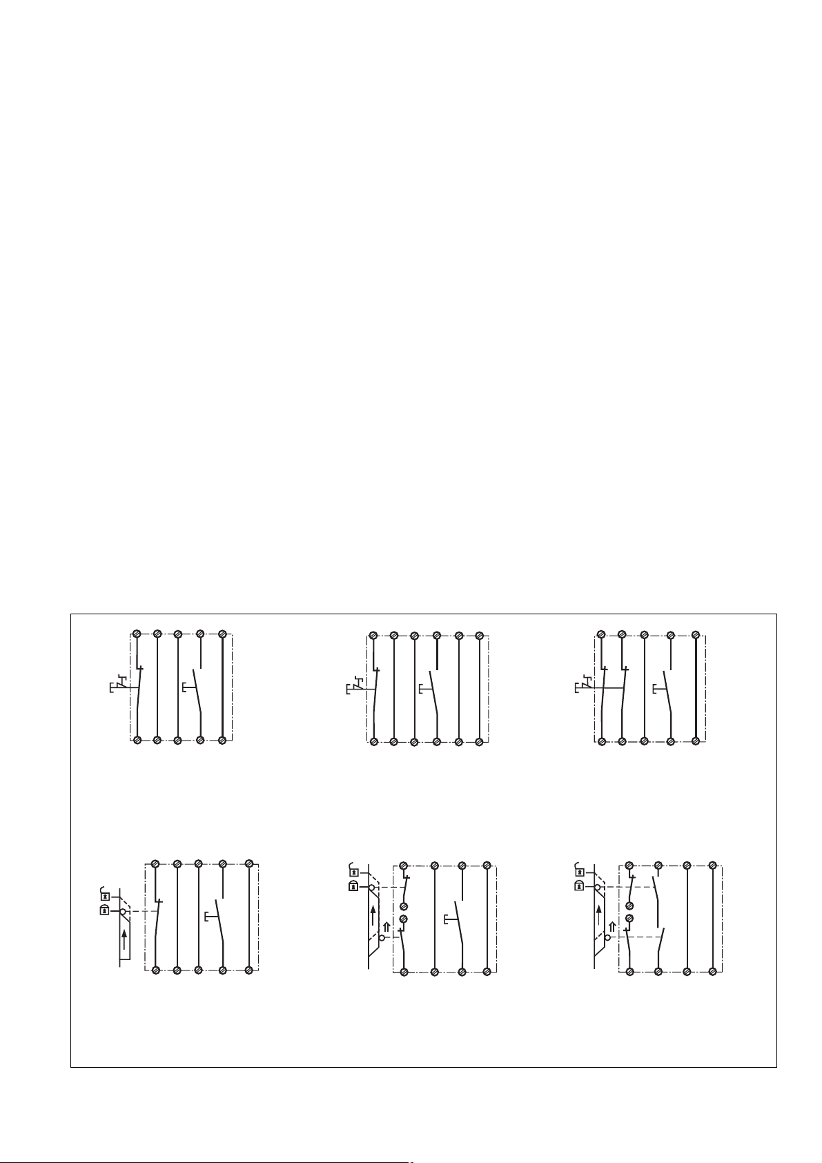
Anwendung
In Fig. 3 ... Fig. 9 sind Anschlussbeispiele für
Not-Halt-Beschaltung mit manuellem und
überwachtem Start sowie Schutztüransteuerungen.
S3
S33
S34
S12
S3
Y1
Y2
S33
Y1
S11 S12
S1
S12
S52
S21
S22
Fig. 3: Eingangskreis einkanalig, manueller
Start/Single-channel input circuit, manual
reset/Commande par 1 canal, validation
manuelle
S11
S21
S1
Use
In Fig. 3 ... Fig. 9, there are example
connections for E-STOP wiring with manual
and monitored starts, as well as safety gate
controls.
S3
S33
S34
S11
S3
Y1
S37Y1Y2
S12
Y1
S11 S12
S1
S12
S52
S21
S22
Fig. 4: Eingangskreis einkanalig, überwachter Starttaster/Single-channel input circuit,
monitored reset/Commande par 1 canal,
surveillance du poussoir de validation
S21
S1
S22
S11
S2
Application
Les figures 3 à 9 représentent des exemples
de raccordement pour câblage d’ARRÊT
D’URGENCE avec réarmement manuel autocontrôlé et commandes de protecteurs
mobiles.
Fig. 5: Eingangskreis zweikanalig, manueller
Start, Querschlusserkennung/Two-channel
input circuit, manual reset, detection of
shorts across the input contacts/Commande
par 2 canaux, validation manuelle, détection
des courts-circuit
S52
S22
S12
Fig. 6: Schutztürsteuerung einkanalig,
manueller Start/Single-channel safety gate
control, manual reset/Surveillance de
protecteur, commande par 1 canal, validation
manuelle
S34
Y2
S12
S52
S34
Y2
Fig. 7: Schutztürsteuerung zweikanalig,
manueller Start/Two-channel safety gate
control, manual reset/Surveillance de
protecteur, commande par 2 canaux, validation
manuelle
- 5 -
Fig. 8: Schutztürsteuerung zweikanalig,
automatischer Start/Two channel safety gate
control,automatic reset/Surveillance de
protecteur, commande par 2 canaux,
validation automatique
Page 6

S3
S33S21S12
Y1
S37
GND
OSSD
S11
24 V DC
S12 S22 S34S52
Fig. 9: Lichtschrankensteuerung, zweikanalig, Querschlusserkennung durch BWS,
überwachter Start/Dual-channel light curtain
control, short circuit detection via ESPE,
monitored reset/Commande par 2 canaux
par barrage immatériel ,surveillance du
poussoir de validation
betätigtes Element/Switch activated/élément actionné
Tür nicht geschlossen/Gate open/porte ouverte
Tür geschlossen/Gate closed/porte fermée
S1/S2: Not-Halt- bzw. Schutztürschalter/Emergency Stop Button, Safety Gate Limit Switch/
Poussoir AU, détecteurs de position
S3: Starttaster/Reset button/Poussoir de réarmement
Fehler - Störungen
• Erd- oder Querschluss bei PNOZ p1p:
LED "FAULT" leuchtet, die LED "POWER"
leuchtet nicht. Eine elektronische Sicherung bewirkt das Öffnen der Ausgangskontakte der Erweiterungsmodule. Nach
Wegfall der Störungsursache und
Abschalten der Betriebsspannung für ca. 1
Minute ist das Gerät wieder betriebsbereit.
• Fehler an PNOZ p1p Erweiterungsgeräten:
Halbleiterausgang Y35 sperrt
(Sammelstörmeldung)
• LED "POWER" leuchtet nicht: Kurzschluss
oder Versorgungsspannung fehlt
Faults – Interference
• Earthing faults or short circuits in the
PNOZ p1p:
the “FAULT” LED will illuminate, but not
the “POWER” LED. An electronic fuse
causes the output contacts to open. Once
the cause of the fault has been removed
and operating voltage is switched off, the
unit will be ready for operation after
approximately 1 minute.
• PNOZ p1p expander unit faults: Semiconductor output Y35 disabled (collective fault
message)
• LED "Power" is not illuminated if shortcircuit or the supply voltage is lost.
Erreurs – Dysfonctionnements
• Mise à la terre et court-circuit au niveau du
PNOZ p1p :
LED “FAULT” allumée et LED “POWER”
éteinte. Un fusible électronique ouvre les
contacts de sortie des modules
d’extension. Une fois la cause du défaut
éliminée et la tension d’alimentation
coupée, l’appareil est à nouveau prêt à
fonctionner après environ 1 minute.
• Erreur au niveau des modules d’extension
du PNOZ p1p : la sortie statique Y35 est
bloquée (message d’erreur groupé)
• LED "Power" éteinte: tension
d'alimentation non présente ou courtcircuit interne.
Technische Daten/Technical Data/Caractéristiques techniques
Versorgungsspannung UB/Operating Voltage UB/Tension d’alimentation U
Spannungstoleranz UB/Voltage Tolerance UB/Plage de la tension d’alimentation U
Leistungsaufnahme bei UB/Power Consumption/Consommation pour U
B
B
B
Restwelligkeit/Residual Ripple/Ondulation résiduelle 160 %
Min. Eingangswiderstand im Einschaltmoment/Min. input resistance in the starting torque/
Résistance d'entrée min. au moment de la mise en marche 252 Ohm
Gleichzeitigkeit/Simultaneity/Désynchronisme S11-S12, S12-S22 150 ms
Wiederbereitschaftszeitzeit/Recovery Time/Temps de réarmement 300 ms
Einschaltverzögerung/Switch-on delay/Temps d’enclenchement
überwachter Start/Monitored Reset/Surveillance du poussoir de validation max.180 ms (nach Loslassen des Start-
automat. oder manueller Start/Automatic or manual Reset/ Validation automatique ou manuelle
Rückfallverzögerung /Delay-on De-Energisation /Temps de retombée K1/K2
bei Not-Halt/with E-Stop/en cas d'AU max. 25 ms
bei Netzausfall/with loss of supply/en cas de coupure d'alimentation max. 1 s
Spannung und Strom an/Voltage and Current at/Tension et courant à
S11, S12, S21, S22, S33, S34, S37, Y1, Y2 24 V DC, 50 mA
Halbleiterausgänge/Semiconductor output/Sorties statiques 24 V DC, 20 mA kurzschlussfest/short circuit
Externe Spannungsversorgung für Halbleiterausgang/External voltage supply for semiconductor output/Alimentation externe pour le sortie statique 24 V DC, ± 20%
Überbrückung bei Spannungseinbrüchen/Max. supply interruption before
de-energisation/tenue aux micro-coupures ca./appx./env. 20 ms
Max. Gesamteitungswiderstand R
(input circuit)/résistivité de câblage totale max. R
einkanalig/single-channel/Commande par 1 canal 60 Ω
(Eingangskreis) /Max. total cable resistance R
lmax
(Circuits d’entrée)
lmax
lmax
zweikanalig ohne Querschlusserkennung/dual-channel without detection of shorts across the
input contacts/command par 2 canaux sans détection des courts-circuit 120 Ω
zweikanalig mit Querschlusserkennung/dual-channel with detection of shorts across the
input contacts/command par 2 canaux avec détection des courts-circuit 30 Ω
24 V DC
-15 % ... +10 %
3 W + Last Erweiterungsmodule/load
expander modules/charge modules
d´expansion
tasters/when the starter button is released/
après poussoir de réarmement est ouvert)
max. 250 ms
proof/
protégées contre les courts-circuits
- 6 -
Page 7

Umgebungstemperatur/Operating Temperature/Température d’utilisation -10 ... + 55 °C
Lagertemperatur/Storage Temperature/Température de stockage -40 ... +85 °C
Klimabeanspruchung/Climate Suitability/Conditions climatiques EN 60068-2-78
Luft- und Kriechstrecken nach/Airgap Creepage to/Cheminement et claquage d'après EN 60947-1
Verschmutzungsgrad/Pollution degree/Niveau d'encrassement 2
Überspannungskategorie/Overvoltage category/Catégorie de surtensions III
Bemessungsisolationsspannung/Rated insulation voltage/Tension assignée d’isolement 60 V
Bemessungsstoßspannungsfestigkeit/Rated impulse withstand voltage/Tension assignée
de tenue aux chocs 0,8 kV
EMV/EMC/CEM EN 60947-5-1, EN 61000-6-2
Schwingungen nach/Vibrations to/Vibrations d'après EN 60068-2-6 Frequenz/Frequency/Frequence: 10 ... 55 Hz
Schutzart/Protection/Indice de protection
Einbauraum/Min. mounting (eg. panel)/Lieu d'implantation (ex. armoire) IP54
Gehäuse/Housing/Boîtier IP30
Klemmenbereich/Terminals/Bornes IP20
Querschnitt des Außenleiters/Cable cross section/Capacité de raccordement
1 Leiter flexibel/1 Core flexible/1 Conducteur souple 0,5 ... 2,5 mm2, 24 - 12 AWG
2 Leiter gleichen Querschnitts/2 cables with the same cross/2 câbles de même diamètre
flexibel mit Aderendhülse ohne Kunststoffhülse/flexible with crimp connectors without 0,5 ... 1 mm2, 24 - 16 AWG
insulating sleeve/souple avec embout sans chapeau plastique
flexibel ohne Aderendhülse oder mit TWIN-Aderendhülse/flexible without crimp 0,5 ... 1,5 mm2, 24 - 16 AWG
connectors or with TWIN crimp/souple sans embout ou avec embout TWIN
Anzugsdrehmoment für Anschlussklemmen (Schrauben)/Torque setting for connection
terminal screw/couple de serrage (bornier) 0,5 Nm
Gehäusematerial/Housing material/Matériau boîtier Kunststoff/Plastic/Plastique
Gehäuse/Housing/Boîtier PPO UL 94 V0
Front/Front/Face avant ABS UL 94 V0
Einbaulage/Mounting position/Position de montage waagrecht/horizontal/horizontal
Abmessungen H x B x T/Dimensions H x W x D/Dimensions H x P x L 94 x 45 x 135 mm (3.70" x 1.77" x 5.31")
Gewicht/Weight/Poids 287 g
Amplitude/Amplitude/Amplitude: 0,35 mm
Es gelten die 2008-06 aktuellen Ausgaben
der Normen
The version of the standards current at
2008-06 shall apply
Bestelldaten/Order reference/Caractéristiques
Typ/
Type/
Type
PNOZ p1p
Merkmale/
Features/
Caractéristiques
24 V DC
Se référer à la version des normes en vigeur
au 2008-06.
Klemmen/
Terminals/
Borniers
Schraubklemmen/screw terminals/borniers à vis
Bestell-Nr./
Order no./
Référence
773 300
- 7 -
Page 8

Abmessungen in mm (")/Dimensions in mm (")/Dimensions en mm (")
135 (5.31")
121 (4.76")
EG-Konformitätserklärung:
Diese(s) Produkt(e) erfüllen die Anforderungen der Richtlinie 2006/42/EG über Maschinen des europäischen Parlaments und des
Rates.
Die vollständige EG-Konformitätserklärung
finden Sie im Internet unter www.pilz.com
Bevollmächtigter: Norbert Fröhlich,
Pilz GmbH & Co. KG, Felix-Wankel-Str. 2,
73760 Ostfildern, Deutschland
94 (3.70")
EC Declaration of Conformity:
This (these) product(s) comply with the
requirements of Directive 2006/42/EC of the
European Parliament and of the Council on
machinery.
The complete EC Declaration of Conformity
is available on the Internet at www.pilz.com
Authorised representative: Norbert Fröhlich,
Pilz GmbH & Co. KG, Felix-Wankel-Str. 2,
73760 Ostfildern, Germany
45
(1.77")
Déclaration de conformité CE :
Ce(s) produit(s) satisfait (satisfont) aux
exigences de la directive 2006/42/CE relative
aux machines du Parlement Européen et du
Conseil.
Vous trouverez la déclaration de conformité
CE complète sur notre site internet
www.pilz.com
Représentant : Norbert Fröhlich,
Pilz GmbH & Co. KG, Felix-Wankel-Str. 2,
73760 Ostfildern, Allemagne
Technischer Support
+49 711 3409-444 +49 711 3409-444
...
In vielen Ländern sind wir durch
unsere Tochtergesellschaften und
Handelspartner vertreten.
Nähere Informationen entnehmen
Sie bitte unserer Homepage oder
nehmen Sie Kontakt mit unserem
Stammhaus auf.
Technical support
... ...
In many countries we are
represented by our subsidiaries
and sales partners.
Please refer to our Homepage
for further details or contact our
headquarters.
Assistance technique
+49 711 3409-444
Nos filiales et partenaires
commerciaux nous représentent
dans plusieurs pays.
Pour plus de renseignements,
consultez notre site internet ou
contactez notre maison mère.
- 8 -
www
www.pilz.com
Pilz GmbH & Co. KG
Felix-Wankel-Straße 2
73760 Ostfildern, Germany
Telephone: +49 711 3409-0
Telefax: +49 711 3409-133
E-Mail: pilz.gmbh@pilz.de
Originalbetriebsanleitung/Original instructions/Notice originale
20674-6NL-04, 2010-11 Printed in Germany
Page 9

20674-6NL-04
PNOZ p1p
4 E Instrucciones de uso
4 I Istruzioni per l`uso
4 NL Gebruiksaanwijzing
Prescripciones de seguridad
• El dispositivo tiene que ser instalado y
puesto en funcionamiento exclusivamente
por personas que estén familiarizadas,
tanto con estas instrucciones de uso
como con las prescripciones vigentes
relativas a la seguridad en el trabajo y a
la prevención de accidentes. Hay que
observar tanto las prescripciones VDE
como las prescripciones locales, especialmente en lo que se refiere a las
medidas de protección.
• Durante el transporte, el almacenaje y el
funcionamiento hay que atenerse a las
condiciones conforme a EN 60068-2-6
(ver datos técnicos).
• La garantía se pierde en caso de que se
abra la carcasa o se lleven a cabo
modificaciones por cuenta propia.
• Montar el dispositivo dentro de un
armario de distribución; en caso contrario
es posible que el polvo y la suciedad
puedan afectar el funcionamiento.
Campo de aplicación adecuado
El dispositivo básico PNOZ p1p para el
sistema modular de seguridad PNOZpower
está diseñado para ser empleado en
•
dispositivos de PARADA DE EMERGENCIA
• circuitos de seguridad según EN 60204-1
(VDE 0113-1) y IEC 60204-1 (p. ej. con
cubiertas móviles)
Norme di sicurezza
• Il dispositivo può venire installato e
messo in funzione solo da persone che
hanno acquisito familiarità con le presenti
istruzioni per l’uso e le disposizioni vigenti
in materia di sicurezza di lavoro e
antinfortunistica. Osservare le disposizioni della VDE nonché le norme locali,
soprattutto per quanto riguarda le misure
preventive di protezione.
• Durante il trasporto, l’immagazzinamento
e il funzionamento attenersi alle condizioni prescritte dalla norma EN 60068-2-6
(v. Dati tecnici).
• Se viene aperta la custodia oppure se
vengono apportate modifiche in proprio,
decade qualsiasi diritto di garanzia.
• Montare il dispositivo in un armadio
elettrico; altrimenti la polvere e l'umidità
possono pregiudicare le funzioni.
Uso previsto
Il dispositivo di base PNOZ p1p per il
sistema di sicurezza modulare PNOZpower
è concepito per essere utilizzato in
• dispositivi di arresto di emergenza
• circuiti elettrici di sicurezza conformi alle
norme EN 60204-1 (VDE 0113 Parte -1)
e IEC 60204-1 (per es. in caso di
protezioni mobili)
Veiligheidsvoorschriften
• Het apparaat mag uitsluitend worden
geïnstalleerd en in bedrijf genomen door
personen die vertrouwd zijn met deze
gebruiksaanwijzing en met de geldende
voorschriften op het gebied van arbeidsveiligheid en ongevallenpreventie. Neemt
u de van toepassing zijnde Europese
richtlijnen en de plaatselijke voorschriften
in acht, in het bijzonder m.b.t. veiligheidsmaatregelen.
• Neemt u bij transport, opslag en in bedrijf
de richtlijnen volgens EN 60068-2-6 in
acht (zie technische gegevens).
• Het openen van de behuizing of het
eigenmachtig veranderen van de
schakeling heeft verlies van de garantie
tot gevolg.
• Monteert u het apparaat in een schakelkast. Stof en vochtigheid kunnen anders
de werking nadelig beïnvloeden.
Gebruik volgens de voorschriften
De basismodule PNOZ p1p van het
modulaire veiligheidssysteem PNOZpower
is bestemd voor gebruik in
• noodstopvoorzieningen
• veiligheidscircuits volgens EN 60204-1
(VDE 0113-1) en IEC 60204-1 (b.v. bij
beweegbare afschermingen)
Descripción del dispositivo
El módulo de ampliación PNOZ p1p está
montado dentro de una carcasa P-01. La
tensión de alimentación es de 24 V CC.
Características:
• Posibilidad de conexión para pulsador de
PARADA DE EMERGENCIA, final de
carrera de seguridad de puerta protectora
y pulsador de rearme
• Indicador de estado para estado de
conmutación de los circuitos de entrada y
salida, circuito de rearme, tensión de
alimentación y fallo
• Circuito de realimentación para la
supervisión de contactores externos
• 2 salidas por semiconductores avisan
disposición para el servicio o fallo (aviso
colectivo de errores para PNOZ p1p y
para el módulo de ampliación con
contacto a tierra o contacto transversal)
• Salida para la excitación de módulos de
ampliación por el bus PNOZpower
• Conectables como máx. 4 módulos de
ampliación
• Conexión entre el PNOZ p1p y los
módulos de ampliación a través del bus
PNOZpower mediante puente insertable
en la parte posterior del dispositivo
Descrizione
Il dispositivo base PNOZ p1p è alloggiato in
una custodia P-01. La tensione di alimentazione è di 24 V DC.
Caratteristiche:
• Possibilità di collegamento per pulsante di
arresto di emergenza, finecorsa riparao
mobile e pulsante di start
• Visualizzazione di stato di commutazione
dei circuiti di ingresso e uscita, circuito di
start, tensione di alimentazione e di
eventuali guasti
• Circuito di retroazione per il controllo di
relè esterni
• 2 uscite a semiconduttore segnalano la
preparazione all’uso o lo stato di anomalia del dispositivo (messaggio di errore
generale per PNOZ p1p ed i moduli di
espansione nel caso di guasto a terra o
cortocircuito)
• Uscita per il comando dei moduli di
ampliamento su bus PNOZpower
• Max. 4 moduli di espansione collegabili
• Collegamento tra PNOZ p1p e moduli di
espansione mediante bus PNOZpower
con ponticello sul retro del dispositivo
Apparaatbeschrijving
De basismodule PNOZ p1p is in een
P-01-behuizing ondergebracht. De
voedingsspanning bedraagt 24 V DC.
Kenmerken:
• Aansluitmogelijkheid voor noodstopknoppen, hekschakelaars en de startknop
• Statusweergave voor schakeltoestand
van ingangs- en uitgangscircuits,
startcircuit, voedingsspanning en storing
• Terugkoppelcircuit voor de bewaking van
externe magneetschakelaars
• 2 halfgeleideruitgangen melden of het
apparaat bedrijfsklaar is dan wel of er een
storing is (verzamelfoutmelding voor
PNOZ p1p en de uitbreidingsmodulen bij
aardsluiting of onderlinge sluiting)
• Uitgang voor het aansturen van de
uitbreidingsmodulen op PNOZpower-bus
uitgevoerd
• Max. 4 uitbreidingsmodulen kunnen
worden aangesloten
• Verbinding tussen de PNOZ p1p en de
uitbreidingsmodulen via PNOZpower-bus
met busconnector op de achterzijde van
het apparaat
- 9 -
Page 10

El dispositivo cumple los requerimientos de
seguridad siguientes:
• El circuito está estructurado de modo
redundante, con autosupervisión
(EN 954-1, categoría 4).
• El equipo de seguridad permanece activo
aún cuando falle uno de los componentes.
• En cada ciclo de conexión/desconexión
de la máquina, se verifica automáticamente, si los relés del
dispositivo de
seguridad abren y cierran correctamente.
Il dispositivo elettrico risponde ai seguenti
requisiti di sicurezza:
• Il circuito è strutturato in modo ridondante
con autocontrollo (EN 954-1, categoria 4).
• Il dispositivo di sicurezza funziona anche
in caso di guasto di un componente.
• Per ciascun ciclo di accensione/spegnimento della macchina, viene eseguita la
verifica automatica della corretta apertura
e chiusura dei relè del dispositivo di
sicurezza.
Het relais voldoet aan de volgende
veiligheidseisen:
• De schakeling is redundant met zelfbewaking opgebouwd (EN 954-1,
categorie 4).
• Ook bij uitvallen van een component blijft
de veiligheidsschakeling werken.
• Bij elke aan/uit-cyclus van de machine
wordt automatisch getest of de relaiscontacten van de veiligheidsvoorziening
correct openen en sluiten.
Descripción del funcionamiento
El dispositivo básico PNOZ p1p sirve, junto
con los módulos de ampliación, para
interrumpir por razones de seguridad un
circuito de seguridad.
El dispositivo se encuentra listo para el
servicio cuando
• se dispone de tensión de alimentación
• está determinado el modo de funcionamiento
• el circuito de realimentación está cerrado
• se ha seleccionado la condición de
rearme
El LED "POWER" se ilumina.
• Circuito de entrada cerrado (p.ej.
pulsador de PARADA DE EMERGENCIA
no accionado):
Se iluminan las indicaciones de estado
"CH.1 IN" y "CH.2 IN". En el bus
PNOZpower está activada la señal de
salida para la excitación de los módulos
de ampliación. El indicador de estado
"OUT" se ilumina.
• Se abre el circuito de entrada (p. ej.
pulsador de PARADA DE EMERGENCIA
accionado):
Se apaga el indicador de estado para
"CH.1 IN" y "CH.2 IN". En el bus
PNOZpower se desactiva la señal de
salida para la excitación de los módulos
de ampliación. El indicador de estado
"OUT" se apaga.
Salidas por semiconductor
La salida por semiconductor Y35 conduce,
cuando está aplicada la tensión de alimentación y no se ha disparado el fusible
interno.
Bloquea en caso de fallo en el dispositivo
básico PNOZ p1p o en uno de los módulos
de ampliación.
La salida por semiconductor Y 32 conduce
cuando los relés K1 y K2 están en posición
activa. Bloquea, cuando el relé está en
posición de reposo.
Descrizione del funzionamento
Il dispositivo base PNOZ p1p insieme ai
moduli di espansione serve per interrompere per motivi di sicurezza un circuito elettrico
di sicurezza.
Il dispositivo è pronto per l’uso quando
• è presente la tensione di alimentazione
• è stato selezionato il modo operativo
• il circuito di retroazione è chiuso
• è stata selezionata la condizione di start
Il LED "POWER" è acceso.
• Il circuito di ingresso è chiuso (p. es.
pulsante di arresto di emergenza non
azionato):
le visualizzazioni di stato per "CH 1 IN" e
"CH 2 IN" sono accese. Il segnale di
uscita sul bus PNOZpower per comandare i moduli di espansione viene attivato.
La visualizzazione di stato "OUT" è
accesa.
• Il circuito di ingresso viene aperto (p. es.
pulsante di arresto di emergenza
azionato):
la visualizzazione di stato per "CH.1 IN" e
"CH.2 IN" si spegne. Il segnale di uscita
sul bus PNOZpower per comandare i
moduli di espansione viene resettato. La
visualizzazione di stato "OUT" si spegne.
Uscite a semiconduttore
L’uscita a semiconduttore Y35 conduce in
presenza della tensione di alimentazione e
se il fusibile interno non è scattato.
Esso blocca il sistema in presenza di un
guasto del dispositivo base PNOZ p1p o di
uno dei moduli di espansione.
L’uscita a semiconduttore Y32 conduce
quando i relè K1 e K2 sono eccitati. Si
chiude quando i relè sono in posizione di
riposo.
Functiebeschrijving
De basismodule PNOZ p1p dient samen
met de uitbreidingsmodulen om een
veiligheidscircuit veilig te onderbreken.
Het apparaat is bedrijfsklaar als
• de voedingsspanning aanwezig is
• de bedrijfsmodus vastgelegd is
• het terugkoppelcircuit gesloten is
• de startvoorwaarde gekozen werd
De LED "POWER" licht op.
• Ingangscircuit gesloten (b.v. noodstopknop niet bediend):
De status-LED’s voor "CH.1 IN" en
"CH.2 IN" lichten op. Het uitgangssignaal
op de PNOZpower-bus voor het aansturen van de uitbreidingsmodulen wordt
ingesteld. De LED "OUT" licht op.
• Ingangscircuit wordt geopend (b.v.
noodstopknop bediend):
De status-LED’s voor "CH.1 IN" en
"CH.2 IN" doven. Het uitgangssignaal op
de PNOZpower-bus voor het aansturen
van de uitbreidingsmodulen wordt
gereset. De LED "OUT" dooft.
Halfgeleideruitgangen
De halfgeleideruitgang Y35 geleidt als de
voedingsspanning ingeschakeld is en de
interne zekering niet geactiveerd is.
Hij geleidt niet bij storing van de basismodule PNOZ p1p of van een van de
uitbreidingsmodulen.
De halfgeleideruitgang Y32 geleidt, als de
relais K1 en K2 bekrachtigd zijn. Hij geleidt
niet als de relais afgevallen zijn.
Y31
Y35
Y32
Y30
&
A2 (0V)
Circuitos de entrada
Circuiti di ingresso
Ingangscircuits
S21 Y1S34
Circuito de rearme y de realimentación
Circuito di start e di retroazione
Start- en terugkoppelcircuit
S37
Fig. 1: Esquema de conexionado interno/Schema di collegamento interno/Intern schema
- 10 -
Y2S33S22S12 S52S11A1 (+)
Salida
Uscita
Uitgange
PNOZpower-Bus
Page 11

Modos de funcionamiento:
• Funcionamiento monocanal: EN 60204-1
(VDE 0113-1) e IEC 60204-1, sin
redundancia en el circuito de entrada, se
detectan los contactos a tierra en el
circuito del pulsador.
• Funcionamiento bicanal: Circuito de
entrada redundante, se detectan los
contactos a tierra en el circuito del
pulsador, así como los contactos
transversales entre los contactos del
pulsador.
• Rearme automático: El dispositivo se
encuentra activo, en cuanto que el
circuito de entrada se encuentra cerrado.
• Rearme manual: El dispositivo se
encuentra activo sólo después de que se
haya accionado un pulsador de rearme.
Mediante ello queda excluida la posibilidad de un rearme automático del
dispositivo después de un corte y un
restablecimiento de la tensión.
• Rearme manual con supervisión: El
dispositivo se encuentra activo sólo
después
vuelto a soltar el pulsador de rearme.
de que se haya accionado y
Modi operativi:
• Funzionamento monocanale: a norma
EN 60204-1 (VDE 0113-1) e
IEC 60204-1, nessuna ridondanza nel
circuito di ingresso; vengono identificati i
guasti a terra nel circuito del pulsante.
• Funzionamento bicanale: circuito di
ingresso ridondante; vengono identificati i
guasti a terra nel circuito del pulsante e i
cortocircuiti tra i contatti dei pulsanti.
• Start automatico: il dispositivo si attiva
non appena il circuito di ingresso viene
chiuso.
• Start manuale: il dispositivo si attiva
quando viene attivato un pulsante di start.
In questo modo si esclude un avvio
automatico del relè dopo l’interruzione e
la ripresa dell’alimentazione di corrente.
• Start manuale controllato: il dispositivo è
attivo solo quando il pulsante di start è
stato azionato e nuovamente rilasciato.
Bedrijfsmodi:
• Eenkanalig bedrijf: EN 60204-1
(VDE 0113-1) en IEC 60204-1, geen
redundantie in het ingangscircuit,
aardsluitingen in het ingangscircuit
worden gedetecteerd.
• Tweekanalig bedrijf: redundant ingangscircuit, aardsluitingen in het
ingangscircuit en onderlinge sluitingen
tussen de ingangscontacten worden
gedetecteerd.
• Automatische start: apparaat is actief,
zodra het ingangscircuit gesloten is.
• Handmatige start: apparaat is pas dan
actief, als een startknop bediend wordt.
Daardoor is een automatische activering
van het relais na uitvallen en terugkeren
van de spanning uitgesloten.
• Handmatige start met bewaking: apparaat
is pas actief als de startknop bediend en
weer losgelaten is.
Montaje
• El dispositivo tiene que ser montado
dentro de un armario de distribución
(IP54 como mínimo). Los dos elementos
de encaje de la parte trasera del dispositivo sirven para fijarlo en una guía
normalizada.
• Montar el aparato en una guía portante
horizontal. Si se monta en otra posición,
no se mantendrán los valores del poder
de corte indicados en las características
técnicas.
• El dispositivo básico PNOZ p1p se puede
montar en cualquier lugar dentro del
sistema de seguridad modular
PNOZpower.
• En la parte posterior del PNOZ p1p hay
dos 2 conectores hembra. El dispositivo
básico PNOZ p1p se conecta a los
módulos de ampliación mediante los
puentes insertables suministrados con el
dispositivo.
Hay que tener en cuenta: ¡Es necesario
insertar una clavija de terminación en
el primer y otra en el último aparato
(véase Fig. 2)!
• Utilizar exclusivamente clavijas de
terminación del sistema de seguridad
modular PNOZpower (marcados: N.º de
referencia 95579).
• Número máximo de módulos admitidos
por un sistema PNOZpower:
- 1 dispositivo básico
- 4 módulos de ampliación
- 1 fuente de alimentación
Montaggio
• Il modulo di sicurezza deve venire
montato in un armadio elettrico (grado di
protezione minimo IP54). Per il fissaggio
su una guida, servono due dispositivi a
scatto sul retro del dispositivo.
• Fissare il dispositivo su una guida
orizzontale. Nel caso di posizioni di
installazione diverse, i valori indicati nei
dati tecnici per il potere di interruzione
non possono essere rispettati.
• Il dispositivo base PNOZ p1p può essere
montato in un punto qualsiasi del sistema
modulare di sicurezza PNOZpower.
• Sul retro del dispositivo PNOZ p1p sono
previste 2 boccole. Il dispositivo base
PNOZ p1p viene collegato ai moduli di
espansione attraverso i ponticelli forniti.
Nota bene: sul primo e sull’ultimo
dispositivo è necessario inserire un
connettore terminale (v. fig. 2).
• Utilizzare soltanto il connettore terminale
per il sistema di sicurezza modulare
PNOZpower (stampigliatura: N. 95579).
• Dotazione massima di un sistema
PNOZpower:
- 1 dispositivo base
- 4 moduli di espansione
- 1 alimentatore di rete
Montage
• Het veiligheidsrelais dient ingebouwd te
worden in een schakelkast (min. IP54).
Bevestiging op een DIN-rail is mogelijk
via twee relaisvoeten op de achterzijde
van het apparaat.
• Monteer het apparaat op een horizontale
draagrail. Bij andere inbouwposities kan
niet voldaan worden aan de waarden die
in de techn. gegevens voor het schakelvermogen zijn opgegeven.
• De basismodule PNOZ p1p kan op een
willekeurige plaats van het modulaire
veiligheidssysteem PNOZpower gemonteerd worden.
• Op de achterzijde van de PNOZ p1p
bevinden er zich 2 busaansluitingen. De
basismodule PNOZ p1p wordt met de
uitbreidingsmodulen verbonden via de
meegeleverde busconnectoren.
Let u op het volgende: Op het eerste en
laatste apparaat moet er een
afsluitconnector geplaatst worden
(zie fig. 2)!
• Alleen afsluitconnectoren voor het
modulaire veiligheidssysteem
PNOZpower gebruiken (voorzien van
artikelnr. 95579).
• Maximale bezetting van een PNOZpowersysteem:
- 1 basismodule
- 4 uitbreidingsmodulen
- 1 voedingsmodule
- 11 -
Page 12

Fuente de
alimentación
Alimentatore
di rete
Voedingsmodule
Dispositivo
básico
Dispositivo
base
Basisrelais
Módulo de amplicación 1
Modulo di espansione 1
Uitbreidingsmodule 1
Módulo de amplicación 4
Modulo di espansione 4
Uitbreidingsmodule 4
95579
Terminador
Connettore terminale
Afsluitconnector
95425
Puente insertable
Ponticello
Busconnector
Fig. 2: Montaje del PNOZ p1p/Montaggio del PNOZ p1p/Montage van de PNOZ p1p
Puesta en marcha
Al poner en marcha el dispositivo hay que
tener en cuenta:
• ATENCIÓN
Los bornes de conexión insertables sólo
se deben insertar o extraer cuando se
encuentren libres de tensión.
• Estado de entrega: puente entre
Y1-Y2 (circuito de realimentación)
• Calculación de la longitud máx. de línea
I
en el circuito de entrada:
máx
R
lmax
=
I
max
Rl / km
R
= resistencia total de línea
máx
máxima (véase datos técnicos)
Rl /km = resistencia de línea/km
Ejemplo (modo de funcionamiento:
bicanal con detección de derivaciones):
- Sección de línea: 1,5 mm
- Temperatura: +25 °C
- Capacidad de línea: 150 nF
- Resistencia de línea total máx. R
- Resistencia de línea Rl/km: 28 Ω/km
- Longitud máx. de línea I
30 W
I
=
max
28 W / km
»
máx
1 km
• Dado que la función de detección de
contactos transversales no es a prueba
de errores, Pilz la comprueba durante el
control final. Después de la instalación
del dispositivo es posible llevar a cabo
una comprobación como se indica a
continuación:
1. Dispositivo listo para el servicio
(contactos de salida cerrados)
2. Cortocircuitar los bornes de ensayo
S12/S22 para la comprobación de
contactos transversales.
3. El fusible en el dispositivo tiene que
dispararse y los contactos de salida
tienen que abrir. Longitudes de línea con
tamaños próximos a la longitud máxima
pueden retardar el disparo del fusible
hasta 2 minutos.
4. Rearmar el fusible: Retirar el cortocircuito y desconectar la tensión de servicio
durante aprox. 1 minuto.
• Utilizar para las líneas material de
alambre de cobre con una resistencia a la
temperatura de 60/75 °C.
• A la hora de conectar interruptores de
proximidad magnetosensibles basados en
contactos Reed, prestar atención a que el
pico máx. de corriente de conexión (en el
lmáx
30 Ω
:
:
Messa in funzione
Alla messa in funzione occorre osservare:
• ATTENZIONE
Innestare e staccare i morsetti di
collegamento inseribili soltanto in
assenza di tensione.
• Unità fornita con: ponticello tra Y1-Y2
(circuito di retroazione)
• Calcolo della lunghezza max. cavo
I
nel circuito di ingresso:
max
R
lmax
=
I
max
Rl / km
R
= max. resistenza del cavo
lmax
totale (vedi "Dati tecnici")
Rl /km = resistenza del cavo/km
Esempio (modo operativo: bicanale con
riconoscimento del cortocircuito):
2
- Sezione trasversale del conduttore:
- Temperatura: +25 °C
- Capacità del cavo: 150 nF
- Max. resistenza cavo totale R
- Resistenza del cavo Rl/km: 28 Ω/km
- Max. lunghezza cavo I
I
max
30 W
=
28 W / km
»
• Poiché la funzione di riconoscimento
cortocircuiti non è esente da errori, essa
viene testata da Pilz durante il controllo
finale. Dopo l’installazione dell’unità è
possibile eseguire un test come indicato
qui di seguito:
1. Unità pronta per il funzionamento
(contatti di uscita chiusi)
2. Cortocircuitare i morsetti per il test
S12/S22 per il rilevamento di
cortocircuiti.
3. Il fusibile sull’unità deve scattare e i
contatti di uscita devono aprirsi. Le
lunghezze dei cavi nell’ordine di
grandezza della lunghezza massima
possono ritardare lo scatto del fusibile
fino a 2 minuti.
4. Resettare il fusibile: rimuovere il
cortocircuito e la tensione di esercizio
per 1 minuto circa.
• Per i cavi utilizzare materiale in filo di
rame con una resistenza termica intorno
ai 60/75 °C.
• Durante il collegamento di sensori di
prossimità magnetici con contatti Reed
evitare il sovraccarico del picco massimo di
corrente di inserzione (sul circuito di
ingresso) dei sensori stessi.
max
1 km
:
1,5 mm
:
lmax
30 Ω
95579
Terminador
Connettore terminale
Afsluitconnector
Ingebruikneming
Neem bij ingebruikneming het volgende in
acht:
• LET OP
De steekbare aansluitklemmen alleen in
de spanningsloze toestand uittrekken en
plaatsen.
• Toestand bij levering: brug tussen Y1-Y2
(terugkoppelcircuit)
• Berekening van de max. kabellengte I
in het ingangscircuit:
R
lmax
=
I
max
Rl / km
R
= max. weerstand
lmax
totale kabel (zie technische gegevens)
Rl /km = kabelweerstand/km
Voorbeeld (bedrijfsmodus: tweekanalig
met detectie van onderlinge sluiting):
2
- Kabeldoorsnede: 1,5 mm
- Temperatuur: +25 °C
- Kabelcapaciteit: 150 nF
- Max. weerstand totale kabel R
- Kabelweerstand Rl/km: 28 Ω/km
- Max. kabellengte I
30 W
I
=
max
28 W / km
• Omdat de functie detectie van onderlinge
sluiting niet enkelfoutveilig is, wordt deze
door Pilz tijdens de eindcontrole getest.
Een controle na de installatie van het
apparaat is als volgt mogelijk:
1. Apparaat bedrijfsklaar (uitgangscontacten gesloten)
2. De testklemmen S12/S22 kortsluiten
om de detectie van onderlinge sluiting te
testen.
3. De zekering in het apparaat moet
geactiveerd worden en de uitgangscontacten moeten opengaan. Kabellengten van ongeveer de maximale lengte
kunnen het activeren van de zekering met
max. 2 minuten vertragen.
4. Zekering resetten: de kortsluiting
ongedaan maken en de voedingsspanning voor ca. 1 minuut uitschakelen.
• Kabelmateriaal van koperdraad met een
temperatuurbestendigheid van 60/75 °C
gebruiken.
• Zorg er voor, dat bij het aansluiten van
magnetische, op basis van Reedcontacten gebaseerde
naderingsschakelaars deze niet wordt
overbelast door de maximale inschakel
piekstroom (op ingangscircuit).
max
»
:
1 km
lmax
max
2
:
30 Ω
- 12 -
Page 13

circuito de entrada) no sobrecargue el
interruptor de proximidad.
• El par de apriete de los tornillos de los
bornes de conexión debe ser 0,5 Nm.
• Respetar sin falta las indicaciones del
capítulo "Datos técnicos".
Procedimiento:
• Tensión de alimentación:
- Aplicar tensión de alimentación en los
bornes A1 (L+) y A2 (L-).
- En caso de utilizarse la fuente de
alimentación PNOZ pps1p, los
dispositivos son alimentados a través
del bus PNOZpower.
En este caso, tener en cuenta: No
debe conectarse tensión de alimentación externa en A1(+) y A2(-).
• Circuito de entrada:
- Monocanal: puentear S21-S22 y
S12-S52. Conectar el contacto de
reposo del elemento de disparo en S12
y S11.
- Bicanal sin detección de contactos
transversales: puentear S21- S22,
conectar el contacto de reposo del
elemento de disparo en
S11-S12/S11-S52.
- Bicanal con detección de contactos
transversales: puentear S11- S52,
conectar el contacto de reposo del
elemento de disparo en
S11-S12/S21-S22.
• Circuito de rearme:
Modo monocanal y bicanal sin detección
de contactos transversales (conectar
bicanal contra +24 V):
- Rearme automático: puentear S33-S34
- Rearme manual: pulsador en S33-S34
- Rearme manual con supervisión:
pulsador entre S33-S34, puentear
Y1-S37.
Modo bicanal con detección de contactos
transversales:
- Rearme automático: puentear
S12-S34.
- Rearme manual: pulsador entre
S12-S34
- Rearme manual con supervisión:
pulsador entre S12-S34, puentear
Y1-S37.
Cuando se acciona el pulsador de
rearme, se ilumina el LED "START".
Solamente después de soltarse el
pulsador de rearme, el dispositivo está
listo para el servicio. El LED "START"
se apaga.
• Circuito de realimentación:
Puente en Y1-Y2 o conectar contactores
externos.
• Tensión de alimentación de 24 V para las
salidas por semiconductores: Conectar
+24 V DC en el borne Y31 y 0 V en el
borne Y30.
Si la señal de salida para la excitación de
los dispositivos de ampliación en el bus
PNOZpower está activa, se iluminan los
indicadores de estado "CH.1 IN", "CH.2 IN"
y "OUT". El dispositivo se encuentra listo
para el servicio.
Si se abre el circuito de entrada, entonces
la señal de salida en el bus PNOZpower no
está activa. El indicador de estado "OUT" se
apaga.
• La coppia di serraggio massima delle viti
sui morsetti deve essere di 0,5 Nm.
• Attenersi assolutamente alle indicazioni
riportate al capitolo "Dati tecnici".
Procedura:
• Tensione di alimentazione:
- Alimentare la tensione di alimentazione
ai morsetti A1 (L+) e A2 (L-).
- Utilizzando l’alimentatore PNOZ pps1p
gli apparecchi vengono alimentati
tramite il bus PNOZpower.
Ricordarsi che: ai morsetti A1 (+) e
A2 (-) non deve essere collegata
nessuna tensione di alimentazione
esterna.
• Circuito di ingresso:
- monocanale: cavallottare S21-S22 e
S12-S52. Collegare il contatto NC
dell’elemento di commutazione con
S12 e S11.
- bicanale senza riconoscimento del
cortocircuito: cavallottare S21-S22;
collegare il contatto NC dell’elemento di
commutazione con S11-S12/S11-S52.
- bicanale con riconoscimento del
cortocircuito: cavallottare S11-S52;
collegare il contatto NC dell’elemento di
commutazione con S11-S12/S21-S22.
• Circuito di start:
funzionamento monocanale o bicanale
senza riconoscimento del cortocircuito
(bicanale commutato verso +24 V):
- Start automatico: cavallottare S33-S34.
- Start manuale: pulsante su S33-S34
- Start manuale controllato: cavallottare il
pulsante tra S33-S34, Y1-S37.
Funzionamento bicanale con riconoscimento cortocircuito:
- Start automatico: cavallottare S12-S34.
- Start manuale: pulsante tra S12-S34
- Start manuale controllato: cavallottare il
pulsante tra S12-S34, Y1-S37.
Azionando il pulsante di start il LED
"START" si accende. L’apparecchio è
pronto a funzionare soltanto dopo il
rilascio del pulsante di start. Il LED
"START" è spento.
• Circuito di retroazione:
Collegare i ponticelli a Y1-Y2 o relè
esterni.
• Tensione di alimentazione da 24 V per le
uscite a semiconduttore: collegare +24 V
DC al morsetto Y31 e 0 V al morsetto
Y30.
Se il segnale di uscita per il comando dei
dispositivi di espansione sul bus
PNOZpower è attivo, le visualizzazioni
"CH.1 IN", "CH.2 IN" e "OUT" si accendono.
Il dispositivo è pronto per l’uso.
Se il circuito di entrata viene aperto, il
segnale di uscita sul bus PNOZpower non è
attivo. Il LED "OUT" si spegne.
• Het aanhaalmoment van de schroeven op
de aansluitklemmen moet 0,5 Nm
bedragen.
• Aanwijzingen in het hoofdstuk "Technische gegevens” beslist opvolgen.
Instelprocedure:
• Voedingsspanning:
- Voedingsspanning op klemmen A1 (L+)
en A2 (L-) aansluiten
- Bij gebruik van de voedingsmodule
PNOZ pps1p worden de apparaten via
de PNOZpower-bus gevoed.
Let in dit geval op het volgende: Er
mag geen externe voedingsspanning
op A1(+) en A2 (-) aangesloten zijn.
• Ingangscircuit:
- Eenkanalig: S21 met S22 en S12 met
S52 verbinden. Verbreekcontact van
bedieningsorgaan op S12 en S11
aansluiten.
- Tweekanalig zonder detectie van
onderlinge sluiting: S21-S22 verbinden;
verbreekcontact van bedieningsorgaan
op S11-S12/S11-S52 aansluiten.
- Tweekanalig met detectie van onder-
linge sluiting: S11-S52 verbinden;
verbreekcontact van bedieningsorgaan
op S11-S12/S21-S22 aansluiten.
• Startcircuit:
Een- en tweekanalig bedrijf zonder
detectie van onderlinge sluiting
(tweekanalig naar +24 V geschakeld):
- Automatische start: S33-S34 verbin-
den.
- Handmatige start: knop op S33-S34
- Handmatige start met bewaking: knop
tussen S33-S34, Y1-S37 verbinden.
Tweekanalig bedrijf met detectie van
onderlinge sluiting:
- Automatische start: S12-S34 verbin-
den.
- Handmatige start: knop tussen
S12-S34
- Handmatige start met bewaking: knop
tussen S12-S34, Y1-S37 verbinden.
Bij het bedienen van de startknop licht
de LED "START" op. Pas na het
loslaten van de startknop is het
apparaat bedrijfsklaar. De LED
"START" licht niet meer op.
• Terugkoppelcircuit:
Brug op Y1-Y2 of contacten van externe
magneetschakelaars aansluiten.
• 24 V voedingsspanning voor halfgeleideruitgangen: +24 V DC op klem Y31 en 0 V
op klem Y30 aansluiten.
Als het uitgangssignaal voor het aansturen
van de uitbreidingsmodulen op de
PNOZpower-bus actief is, dan lichten de
status-LED’s "CH.1 IN", "CH.2 IN" en "OUT"
op. Het apparaat is bedrijfsklaar.
Als het ingangscircuit geopend wordt, dan is
het uitgangssignaal op de PNOZpower-bus
niet actief. De LED "OUT" dooft.
- 13 -
Page 14

Activar de nuevo
• Cerrar el circuito de entrada.
• Con rearme manual sin supervisión
accionar adicionalmente el pulsador entre
S33 y S34, con rearme manual con
supervisión accionar y volver a soltar el
pulsador.
Los indicadores de estado vuelven a
iluminarse y los contacos de seguridad
están cerrados.
Riattivazione
• Chiudere il circuito di ingresso.
• In caso di start manuale senza controllo,
azionare il pulsante tra S33 e S34; in
caso di start manuale con controllo,
azionare e rilasciare il pulsante.
Gli indicatori di stato si riaccendono, i
contatti di sicurezza sono chiusi.
Opnieuw activeren
• Ingangscircuit sluiten.
• Bij handmatige start zonder bewaking
tevens de knop tussen S33 en S34
bedienen, bij handmatige start met
bewaking knop bedienen en weer
loslaten.
De status-LED’s lichten weer op, de
veiligheidscontacten zijn gesloten.
Aplicación
En las figuras 3 ... 9 hay ejemplos de
conexión para conexionado de PARADA DE
EMERGENCIA con rearme manual y
supervisado, así como controles de puerta
protectora.
S3
S33
S34
S12
S3
Y1
Y2
S33
Y1
S11 S12
S21
S1
S52
S12
S22
Fig. 3: Circuito de entrada monocanal,
arranque manual/Circuito di ingresso
monocanale, start manuale/Eenkanalig
ingangscircuit, handmatige start
S11
S21
S1
Utilizzo
Dalla fig. 3 ... alla fig. 9 sono illustrati alcuni
esempi di collegamento per l’arresto di
emergenza con start manuale controllato e
comandi per ripari mobili.
S3
S33
S34
S11
S3
Y1
S37Y1Y2
S12
Y1
S11 S12
S1
S12
S52
S21
S22
Fig. 4: Circuito de entrada monocanal,
pulsador de rearme supervisado/Circuito di
ingresso monocanale, pulsante di start
controllato/Eenkanalig ingangscircuit,
bewaakte startknop
S21
S1
S22
S11
S2
Toepassing
In fig. 3 ... fig. 9 zijn aansluitvoorbeelden
gegeven van noodstopschakeling met
handmatige en bewaakte start en hekbewaking.
S3
S33
S12
S34
S1
S2
S21
Y1
Y2
Y1
S11
S11
S21
S1
S12
S22
S52
Fig. 5: Circuito de entrada bicanal, rearme
manual, detección de contactos transversales/Circuito di ingresso bicanale, start
manuale, riconoscimento del cortocircuito/
Tweekanalig ingangscircuit, handmatige
start, detectie van onderlinge sluiting
S11
S52
S11
S12
S22
S52
S34
Y2
Fig. 6: Control de puerta de protección
monocanal, rearme manual/Comando riparo
mobile monocanale, start manuale/
Eenkanalige hekbewaking, handmatige start
S3
S33S21S12
Y1
S37
GND
OSSD
S11
24 V DC
S12 S22 S34S52
Fig. 9: Control de barrera fotoeléctrica,
bicanal, detección de corto circuito
transversal mediante BWS, rearme
supervisado/Controllo barriera fotoelettrica,
bicanale, rilevamento del cortocircuito
trasversale mediante fotocellula, start
controllato/
Tweekanalige lichtschermbewaking, detectie van onderlinge sluiting
door lichtscherm, bewaakte start
S12
Fig. 7: Control de puerta de protección bicanal,
rearme manual/Comando riparo mobile
bicanale, start manuale/Tweekanalige
hekbewaking, handmatige start
S52
S34
Y2
Fig. 8: Control de puerta de protección
bicanal, rearme automático/Comando riparo
mobile bicanale, start automatico/
Tweekanalige hekbewaking, automatische
start
Elemento accionado/Elemento azionato/Bediend element
Puerta no cerrada/Porta non chiusa/Hek open
Puerta cerrada/Porta chiusa/Hek gesloten
S1/S2: PARADA DE EMERGENCIA ó bien interruptor de puerta
protectora/Interruttore dell’ARRESTO DI EMERGENZA,
ovvero del riparo mobile/Noodstop- of hekschakelaar
S3: Pulsador de rearme/Pulsante di start/Startknop
S12
S34
S22
Y2
- 14 -
Page 15

Datos técnicos/Dati tecnici/Technische gegevens
Tensión de alimentación UB/Tensione di alimentazione UB/Voedingsspanning U
Tolerancia de tensión UB/Tolleranza di tensione UB/Spanningstolerantie U
Consumo de energía con UB/Potenza assorbita a UB/Opgenomen vermogen bij U
B
B
B
Ondulación residual/Ondulazione residua/Rimpelspanning
Resistencia de entrada mín. en el instante de la conexión/Resistenza di inserzione min. nella
coppia di avvio/Min. ingangsweerstand tijdens het inschakelmoment
Simultaneidad/Simultaneità/Gelijktijdigheid
Tiempo de recuperación/Tempo di ripristino/Resettijd
Retardo a la conexión/Ritardo d’inserzione/Inschakelvertraging
Rearme supervisado/start controllato/bewaakte start
Rearme automático o manual/start automatico o manuale/automat. of handmatige start
Retardo a la desconexión/Ritardo tempo di sgancio/Afvalvertraging
con PARADA DE EMERGENCIA/in caso di arresto di emergenza/Bij noodstop
con interrupción del suministro eléctrico/in caso di perdita di alimentazione/
Bij uitvallen spanning
Tensión y corriente en/Tensione e corrente su/Spanning en stroom op
S11, S12, S21, S22, S33, S34, S37, Y1, Y2
Salidas por semiconductor/Uscite a semiconduttore/Halfgeleideruitgangen
Suministro externo de tensión para salida por semiconductor/Alimentazione di tensione esterna
per uscita a semiconduttore/Externe voedingsspanning voor halfgeleideruitgang
Inmunidad a cortes de tensión/Esclusione in caso di mancanza tensione/Maximale
spanningsonderbreking
Resistencia de línea total máxima R
(circuito di ingresso)/Max. weerstand totale kabel R
monocanal/monocanale/eenkanalig
(circuito de entrada)/Max. resistenza cavo totale R
lmáx
(ingangscircuit)
lmáx
lmax
bicanal sin detección de contactos transversales/bicanale senza riconoscimento
del cortocircuito/tweekanalig zonder detectie van onderlinge sluiting
bicanal con detección de contactos transversales/bicanale con riconoscimento
del cortocircuito/tweekanalig met detectie van onderlinge sluiting
Temperatura ambiente/Temperatura ambiente/Omgevingstemperatuur
Temperatura de almacenaje/Temperatura di magazzinaggio/Opslagtemperatuur
Condiciones climáticas/Sollecitazione climatica/Klimaatcondities
Dist. fuga y dispersión superficial según/Intraferri d’aria, vie di dispersione secondo norma/
Lucht- en kruipwegen volgens EN 60947-1
Grado de suciedad/Grado di contaminazione/Vervuilingsgraad
Categoria de sobretensión/Categoria di sovratensione/Overstruingscategorie
Tensión de aislamiento de dimensionado/Tensione nominale di isolamento/Nominale
isolatiespanning
Resistencia tensión transitoria de dimensionado/Tensione di tenuta agli urti/Nominale
stootspanningbestendigheid
CEM/Compatibilità elettromagnetica/EMC
Vibraciones según/Vibrazioni secondo norma/Trillingsbestendigheid volgens
EN 60068-2-6
Grado de protección/Tipo di protezione/Beschermingsgraad
Lugar de montaje/Spazio necessario per il montaggio/Inbouwruimte
Carcasa/Custodia/Behuizing
Zona de bornes/Terminali/Aansluitklemmen
Sección del cable exterior/Sezione trasversale del conduttore esterno/Doorsnede van de
aansluitkabels
1 conductor flexible/conduttore flessibile/draad flexibel
2 conductores de la misma sección/conduttori con la stessa sezione trasversale/draden
met dezelfde doorsnede
flexible con terminal sin revestimiento de plástico/flessibile con capocorda senza
manicotto in plastica/flexibel met adereindhuls zonder kunststofhuls
flexible sin terminal o con terminal TWIN/flessibile senza capocorda o con
capocorda TWIN/flexibel zonder adereindhuls of met TWIN-adereindhuls
Par de apriete para bornes de conexión (tornillos)/Coppia di serraggio per i morsetti (viti)/
Aanhaalmoment voor aansluitklemmen (schroeven)
Material de la carcasa/Materiale custodia/Behuizingsmateriaal
Carcasa/Custodia/Behuizing
Frente/Parte frontale/Front
Posición de montaje/Posizione di installazione/Inbouwpositie
Dimensiones Al x An x P/Misure altezza x larghezza x profondità/Afmetingen h x b x d
Peso/Peso/Gewicht
24 V DC
-15 % ... +10 %
3 W + carga módulos de ampliación/carico
dei moduli di espansione/belasting
uitbreidingsmodulen
160 %
252 Ohm
150 ms
300 ms
max.180 ms (después de soltarse el
pulsador de rearme/dopo il rilascio del
pulsante di start/na loslaten van de
startknop)
max. 250 ms
max. 25 ms
max. 1 s
24 V DC, 50 mA
24 V DC, 20 mA resistente a los
cortocircuitos/a prova di cortocircuito/
kortsluitvast
24 V DC, ± 20%
ca. 20 ms
60 Ω
120 Ω
30 Ω
-10 ... + 55 °C
-40 ... +85 °C
EN 60068-2-78
2
III
60 V
0,8 kV
EN 60947-5-1, EN 61000-6-2
Frecuencia/Frequenza/Frequentie: 10 ... 55 Hz
Amplitud/Ampiezza/Amplitude: 0,35 mm
IP54
IP30
IP20
0,5 ... 2,5 mm2, 24 - 12 AWG
0,5 ... 1 mm2, 24 - 16 AWG
0,5 ... 1,5 mm2, 24 - 16 AWG
0,5 Nm
Plástico/Plastica/Kunststof
PPO UL 94 V0
ABS UL 94 V0
horizontal/orizzontale//horizontaal
94 x 45 x 135 mm (3.70" x 1.77" x 5.31")
287 g
- 15 -
Page 16

Son válidas las versiones actuales de las
normas 2008-06.
Per le norme citate, sono applicate le
versioni in vigore a 2008-06.
Datos de pedido/Dati di ordinazione/Bestelgegevens
Van toepassing zijn de in 2008-06 actuele
versies van de normen.
Tipo/
Tipo/
Type
PNOZ p1p
Características/
Caratteristiche/
Kenmerken
24 V DC
Bornes/
Morsetti/
Klemmen
bornes de tornillo/morsetti a vite/schroefklemmen
Dimensiones en mm (")/Dimensioni in mm (")/Afmetingen in mm (")
135 (5.31")
121 (4.76")
94 (3.70")
Declaración CE de conformidad:
Estos productos cumplen los requisitos de
la Directiva de Máquinas 2006/42/CE del
Parlamento Europeo y del Consejo.
La declaración CE de conformidad completa
pueden encontrarla en la página web de
Internet www.pilz.com
Apoderado: Norbert Fröhlich,
Pilz GmbH & Co. KG, Felix-Wankel-Str. 2,
73760 Ostfildern, Deutschland
Dichiarazione di conformità CE:
Questo(i) prodotto(i) soddisfa i requisiti della
Direttiva 2006/42/CE del Parlamento e del
Consiglio Europeo sulle macchine.
Il testo integrale della Dichiarazione di
conformità CE è disponibile in Internet
all’indirizzo www.pilz.com
Mandatario: Norbert Fröhlich,
Pilz GmbH & Co. KG, Felix-Wankel-Str. 2,
73760 Ostfildern, Germania
Nº de pedido/
N. Ord./
Bestelnr.
773 300
45
(1.77")
EG-conformiteitsverklaring:
Deze produkten voldoen aan de eisen van
de Europese Machinerichtlijn 2006/42/EG.
De volledige EG-conformiteitsverklaring
vindt u op wwww.pilz.com
Gevolmachtige: Norbert Fröhlich,
Pilz GmbH & Co. KG, Felix-Wankel-Str. 2,
73760 Ostfildern, Duitsland
Asistencia técnica
+49 711 3409-444 +49 711 3409-444
...
Estamos representados en
muchos países por nuestros
socios comerciales.
Obtendrá más información a
través de nuestra Homepage
o entrando en contacto con
nuestra casa matriz.
Supporto tecnico
... ...
In molti Paesi siamo rappresentati
da partner commerciali.
Per maggiori informazioni potete
contattarci direttamente o tramite
la nostra Homepage.
Technische Support
+49 711 3409-444
In veel landen zijn wij
vertegenwoordigd door
handelspartners.
Voor meer informatie kunt
u onze homepage raadplegen
of contact opnemen met
ons hoofdkantoor.
- 16 -
www
www.pilz.com
Pilz GmbH & Co. KG
Felix-Wankel-Straße 2
73760 Ostfildern, Germany
Telephone: +49 711 3409-0
Telefax: +49 711 3409-133
E-Mail: pilz.gmbh@pilz.de
Manual de Instrucciones original/Istruzioni originali/Originele bedrijfshandleiding
20674-6NL-03, 2010-11 Printed in Germany
 Loading...