

Page 1

Operating Manual PNOZ mo4p
Operating Manual PNOZ mo4p
PNOZ mo4p
PNOZmulti Modular Safety System
Operating Manual — No. 20942-EN-05
Page 2

This document is a translation of the original document.
All rights to this documentation are reserved by Pilz GmbH & Co. KG. Copies may be made
for internal purposes.
Suggestions and comments for improving this documentation will be gratefully received.
Pilz®, PIT®, PMI®, PNOZ®, Primo®, PSEN®, PSS®, PVIS®, SafetyBUS p®, SafetyEYE®,
SafetyNET p®, the spirit of safety® are registered and protected trademarks of
Pilz GmbH & Co. KG in some countries.
SD means Secure Digital.
Preface
Page 3
Contents
Contents
Contents Page
Chapter 1 Introduction
1.1 Validity of documentation 1-1
1.1.1 Retaining the documentation 1-1
1.2 Overview of documentation 1-2
1.3 Definition of symbols 1-3
Chapter 2 Overview
2.1 Unit structure 2-1
2.1.1 Scope of supply 2-1
2.1.2 Unit features 2-1
2.2 Front view 2-2
Chapter 3 Safety
3.1 Intended use 3-1
3.1.1 System requirements 3-1
3.2 Safety regulations 3-2
3.2.1 Use of qualified personnel 3-2
3.2.2 Warranty and liability 3-2
3.2.3 Disposal 3-2
3.2.4 For your safety 3-3
Chapter 4 Function description
4.1 Device properties 4-1
4.1.1 Integrated protection mechanisms 4-1
4.1.2 Function description 4-1
4.1.2.1 Operation 4-1
4.1.2.2 Internal wiring diagram 4-2
Chapter 5 Installation
5.1 General installation guidelines 5-1
5.1.1 Dimensions 5-1
5.2 Connecting the base unit and expansion
modules
5-2
Chapter 6 Commissioning
6.1 General wiring guidelines 6-1
6.2 Preparing for operation 6-2
6.2.1 Download modified project to the
PNOZmulti safety system
6.2.2 Connection 6-2
6.3 Connection example 6-3
Pilz GmbH & Co. KG, Felix-Wankel-Straße 2, 73760 Ostfildern, Germany
Telephone: +49 711 3409-0, Telefax: +49 711 3409-133, E-Mail: pilz.gmbh@pilz.de
6-2
1
Page 4
Contents
Chapter 7 Operation
7.1 Messages 7-1
7.1.1 Display elements 7-1
7.1.1.1 Display elements for device diagnostics 7-1
Chapter 8 Technical details
8.1 Technical details 8-1
8.2 Service life graph of output relays 8-4
8.3 Maximum capacitive load C (μF) with load
current I (A) at the semiconductor outputs
8.4 Order reference 8-6
8-5
Pilz GmbH & Co. KG, Felix-Wankel-Straße 2, 73760 Ostfildern, Germany
2
Telephone: +49 711 3409-0, Telefax: +49 711 3409-133, E-Mail: pilz.gmbh@pilz.de
Page 5

1 Introduction
1.1 Validity of documentation
11000IntroductionIntroduction1-1.1Validity of docume ntation1100Validity of documenta tion1-Einf Gltigkeit der Dokumentation
This documentation is valid for the product PNOZ mo4p. It is valid until
Einf Einleitung
1.1.1 Retaining the documentation
Retaining the documentation1-Einf Aufbewahren
new documentation is published.
This operating manual explains the function and operation, describes
the installation and provides guidelines on how to connect the product .
This documentation is intended for instruction and should be retained
for future reference.
Pilz GmbH & Co. KG, Felix-Wankel-Straße 2, 73760 Ostfildern, Germany
Telephone: +49 711 3409-0, Telefax: +49 711 3409-133, E-Mail: pilz.gmbh@pilz.de
1-1
Page 6

1 Introduction
1.2 Overview of documentation
1.2Overview of documentation1200Overview of documentation1-Einf_Uebersicht_über_die_Doku_6_Inbetriebnahme
1 Introduction
The introduction is designed to familiarise you with the contents, structure and specific order of this manual.
2 Overview
This chapter provides information on the product's most important features.
3 Safety
This chapter must be read as it contains important information on intended use.
4 Function Description
This chapter describes the product's mode of operation.
5 Installation
This chapter explains how to install the product.
6 Commissioning
This chapter describes the product's commissioning and wiring.
7 Operation
This chapter describes how to operate the product and gives tips in the
case of a fault.
8 Technical Details
This chapter contains the product's technical details and order reference.
1-2
Pilz GmbH & Co. KG, Felix-Wankel-Straße 2, 73760 Ostfildern, Germany
Telephone: +49 711 3409-0, Telefax: +49 711 3409-133, E-Mail: pilz.gmbh@pilz.de
Page 7
1 Introduction
1.3 Definition of symbols
1.3Definition of symbols1300Definition of symbols1-Einfhrung Zeichen
Information that is particularly important is identified as follows:
DANGER!
This warning must be heeded! It warns of a hazardous situation
that poses an immediate threat of serious injury and death and
indicates preventive measures that can be taken.
WARNING!
This warning must be heeded! It warns of a hazardous situation
that could lead to serious injury and death and indicates preventive measures that can be taken.
CAUTION!
This refers to a hazard that can lead to a less serious or minor
injury plus material damage, and also provides information on
preventive measures that can be taken.
NOTICE
This describes a situation in which the product or devices could
be damaged and also provides information on preventive measures that can be taken.
INFORMATION
This gives advice on applications and provides information on
special features, as well as highlighting areas within the text that
are of particular importance.
Pilz GmbH & Co. KG, Felix-Wankel-Straße 2, 73760 Ostfildern, Germany
Telephone: +49 711 3409-0, Telefax: +49 711 3409-133, E-Mail: pilz.gmbh@pilz.de
1-3
Page 8

1 Introduction
1-4
Pilz GmbH & Co. KG, Felix-Wankel-Straße 2, 73760 Ostfildern, Germany
Telephone: +49 711 3409-0, Telefax: +49 711 3409-133, E-Mail: pilz.gmbh@pilz.de
Page 9

2 Overview
2.1 Unit structure
22000OverviewOverview2-2.1Unit structure2100Unit structure2-
2.1.1 Scope of supply
Scope of supply2-Lieferumfang_Brck_774639_modul_BA
2.1.2 Unit features
Unit features2-Gerätemerkmale_Verwendung
Expansion module PNOZ mo4p
Jumper 774 639
Verwendung/Bildunterschrift_multi_Modul
Geraetemerkmale_Zusatz BA Einleitung
Gertemerkmale
Gertemerkmale_Anschlussklemmen_Zubehoer
Geraetemerkmal_Coated Version
Using the product PNOZ mo4p:
Expansion module for connection to a base unit from the PNOZmulti
modular safety system
The product has the following features:
Positive-guided relay outputs:
4 safety outputs
Depending on the application, up to PL e of EN ISO 13849-1 and up
to SIL CL 3 of EN IEC 62061
Can be configured in the PNOZmulti Configurator
Status indicators
Max. 6 PNOZ mo4p units can be connected to the base unit
Plug-in connection terminals:
either spring-loaded terminal or screw terminal available as an accessory (see order reference)
Coated version:
Increased environmental requirements
Pilz GmbH & Co. KG, Felix-Wankel-Straße 2, 73760 Ostfildern, Germany
Telephone: +49 711 3409-0, Telefax: +49 711 3409-133, E-Mail: pilz.gmbh@pilz.de
2-1
Page 10
2 Overview
773536
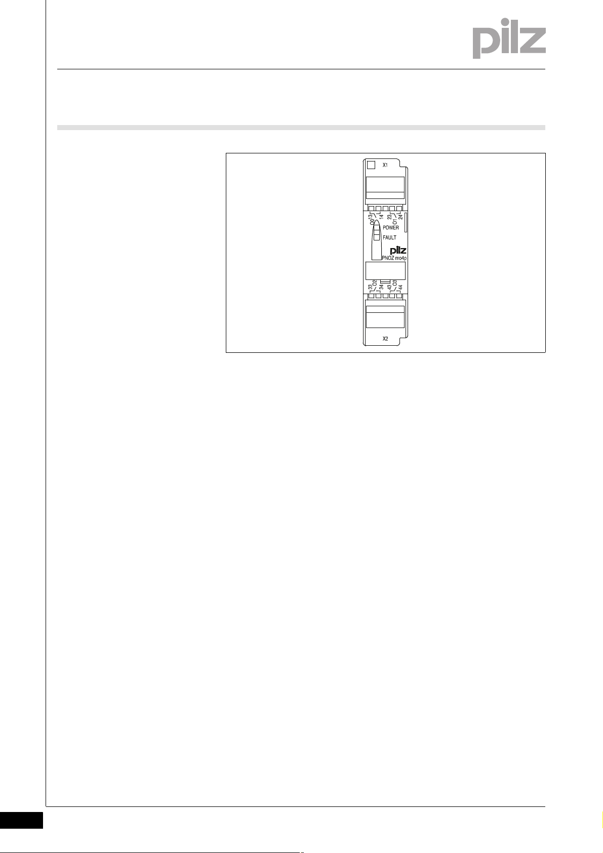
2.2 Front view
2.2Front view2200Front view2-Klemmenbelegung
Legende
Legend:
O0 – O3
Relay outputs
2-2
Pilz GmbH & Co. KG, Felix-Wankel-Straße 2, 73760 Ostfildern, Germany
Telephone: +49 711 3409-0, Telefax: +49 711 3409-133, E-Mail: pilz.gmbh@pilz.de
Page 11

3 Safety
3.1 Intended use
33000SafetySafety3-3.1Intended use3100Intended use3-Bestimmung/Gertebeschreibung_multi_Zusatz_Modul
Bestimmung/Gertebeschreibung_multi_System
Bestimmung/Gertebeschreibung_Zusatz_Coated Version
Bestimmung/Gertebeschreibung_EMV+Ausschluss
The expansion module may only be connected to a base unit from the
PNOZmulti modular safety system.
The modular safety system PNOZmulti is used for the safety-related interruption of safety circuits and is designed for use on:
E-STOP equipment
Safety circuits in accordance with VDE 0113 Part 1 and EN 60204-1
The coated version of the product PNOZ mo4p is suitable for use where
there are increased environmental requirements (see Technical Details).
Intended use includes making the electrical installation EMC-compliant.
The product is designed for use in an industrial environment. It is not
suitable for use in a domestic environment, as this can lead to interference.
3.1.1 System requirements
System requirements3-Systemvoraussetzungen - Verweis auf Produktänderungen
The following is deemed improper use in particular:
Any component, technical or electrical modification to the product
Use of the product outside the areas described in this manual
Use of the product outside the technical details (see chapter entitled
“Technical Details”)
Please refer to the "Product Modifications" document in the "Version
overview" section for details of which versions of the base unit and
PNOZmulti Configurator can be used for this product.
Pilz GmbH & Co. KG, Felix-Wankel-Straße 2, 73760 Ostfildern, Germany
Telephone: +49 711 3409-0, Telefax: +49 711 3409-133, E-Mail: pilz.gmbh@pilz.de
3-1
Page 12

3 Safety
3.2 Safety regulations
3.2Safety regulations3200Safety regulations3-
3.2.1 Use of qualified personnel
Use of qualified personnel3-Sich Qualif. Personal
The products may only be assembled, installed, programmed, commissioned, operated, maintained and decommissioned by competent persons.
A competent person is someone who, because of their training, experience and current professional activity, has the specialist knowledge required to test, assess and operate the work equipment, devices,
systems, plant and machinery in accordance with the general standards
and guidelines for safety technology.
It is the company's responsibility only to employ personnel who:
Are familiar with the basic regulations concerning health and safety /
accident prevention
Have read and understood the safety guidelines given in this descrip-
tion
Have a good knowledge of the generic and specialist standards ap-
plicable to the specific application.
3.2.2 Warranty and liability
Warranty and liability3-Sich Gewhrleistung
3.2.3 Disposal
Disposal3-Si ch Entsorgung
All claims to warranty and liability will be rendered invalid if:
The product was used contrary to the purpose for which it is intended
Damage can be attributed to not having followed the guidelines in the
manual
Operating personnel are not suitably qualified
Any type of modification has been made (e.g. exchanging compo-
nents on the PCB boards, soldering work etc.).
In safety-related applications, please comply with the mission time t
M
in the safety-related characteristic data.
When decommissioning, please comply with local regulations regard-
ing the disposal of electronic devices (e.g. Electrical and Electronic
Equipment Act).
3-2
Pilz GmbH & Co. KG, Felix-Wankel-Straße 2, 73760 Ostfildern, Germany
Telephone: +49 711 3409-0, Telefax: +49 711 3409-133, E-Mail: pilz.gmbh@pilz.de
Page 13

3 Safety
3.2 Safety regulations
3.2.4 For your safety
For your safety3-Zu Ihrer Sicherheit_multi_Module
The unit meets all necessary conditions for safe operation. However,
you should always ensure that the following safety requirements are
met:
This operating manual only describes the basic functions of the unit.
Information on the advanced functions can be found in the online help
for the PNOZmulti Configurator and in the PNOZmulti technical catalogue. Only use these functions after you have read and understood
the documentation. All necessary documentation can be found on the
PNOZmulti Configurator CD.
Do not open the housing or make any unauthorised modifications.
Please make sure you shut down the supply voltage when performing
maintenance work (e.g. exchanging contactors).
Pilz GmbH & Co. KG, Felix-Wankel-Straße 2, 73760 Ostfildern, Germany
Telephone: +49 711 3409-0, Telefax: +49 711 3409-133, E-Mail: pilz.gmbh@pilz.de
3-3
Page 14

3 Safety
3-4
Pilz GmbH & Co. KG, Felix-Wankel-Straße 2, 73760 Ostfildern, Germany
Telephone: +49 711 3409-0, Telefax: +49 711 3409-133, E-Mail: pilz.gmbh@pilz.de
Page 15

4 Function description
4.1 Device properties
44000Function descriptionFunction description4-4.1Device properties4100Device properties4-
4.1.1 Integrated protection mechanisms
Integrated protection mechanisms4-Sicherheitseigenschaften_multi_allgemein
The relay conforms to the following safety criteria:
The circuit is redundant with built-in self-monitoring.
The safety function remains effective in the case of a component fail-
Sicherheitseigenschaften_Relais
4.1.2 Function description
Function description4-
ure.
The relay contacts meet the requirements for safe separation through
increased insulation compared with all other circuits in the safety system.
4.1.2.1 Operation
Operation4-Funktionen_multi_Relais
The expansion module provides additional relay outputs.
The function of the outputs on the safety system depends on the safety
circuit created using the PNOZmulti Configurator. A chip card is used to
download the safety circuit to the base unit. The base unit has 2 microcontrollers that monitor each other. They evaluate the input circuits on
the base unit and expansion modules and switch the outputs on the
base unit and expansion modules accordingly.
The online help on the PNOZmulti Configurator contains descriptions of
the operating modes and all the functions of the PNOZmulti safety system, plus connection examples.
Pilz GmbH & Co. KG, Felix-Wankel-Straße 2, 73760 Ostfildern, Germany
Telephone: +49 711 3409-0, Telefax: +49 711 3409-133, E-Mail: pilz.gmbh@pilz.de
4-1
Page 16

4 Function description
Interface
to previous
module
Interface
to next
module
O0
O1
13
23
14
24
O2
O3
33
43
34
44
4.1 Device properties
4.1.2.2 Internal wiring diagram
Internal wiring diagram4-Blockschaltbild
4-2
Pilz GmbH & Co. KG, Felix-Wankel-Straße 2, 73760 Ostfildern, Germany
Telephone: +49 711 3409-0, Telefax: +49 711 3409-133, E-Mail: pilz.gmbh@pilz.de
Page 17

5 Installation
94 (3.70")
22,5
(0.88")
121 (4.76")
5.1 General installation guidelines
55000InstallationInstallation5-5.1General installation guidelines5100General installation guidelines5-Montage_multi_allgemein
Montage_EMV ESD
The safety system should be installed in a control cabinet with a pro-
tection type of at least IP54. Fit the safety system to a horizontal
mounting rail. The venting slots must face upward and downward.
Other mounting positions could destroy the safety system.
Use the notches on the rear of the unit to attach it to a mounting rail.
Connect the safety system to the mounting rail in an upright position,
so that the earthing springs on the safety system are pressed on to
the mounting rail.
The ambient temperature of the PNOZmulti units in the control cabi-
net must not exceed the figure stated in the technical details, otherwise air conditioning will be required.
To comply with EMC requirements, the mounting rail must have a low
impedance connection to the control cabinet housing.
CAUTION!
Damage due to electrostatic discharge!
Electrostatic discharge can damage components. Ensure
against discharge before touching the product, e.g. by touching
an earthed, conductive surface or by wearing an earthed armband.
5.1.1 Dimensions
Dimensions5-Abmessungen
Pilz GmbH & Co. KG, Felix-Wankel-Straße 2, 73760 Ostfildern, Germany
Telephone: +49 711 3409-0, Telefax: +49 711 3409-133, E-Mail: pilz.gmbh@pilz.de
5-1
Page 18

5 Installation
5.2 Connecting the base unit and expansion modules
5.2Connecting the base unit and expansion modules5200Connecting the base unit and expansion modules5-Montage_multi_Modul_verbind_rechts_BA
Connect the base unit and the expansion modules as described in the
operating manuals for the base modules.
The terminator must be fitted to the last expansion module
Install the expansion module in the position configured in the
Montage_multi_Basis_Verweis_Systemausbau
PNOZmulti Configurator.
Please refer to the document "System Expansion" for details of the
number of modules that can be connected to the base unit and the module types.
5-2
Pilz GmbH & Co. KG, Felix-Wankel-Straße 2, 73760 Ostfildern, Germany
Telephone: +49 711 3409-0, Telefax: +49 711 3409-133, E-Mail: pilz.gmbh@pilz.de
Page 19

6 Commissioning
6.1 General wiring guidelines
66000CommissioningComm issioning6-6.1General wiring guidelines6100General wiring guidelines6-Verdrahtung_multi_M odul
The wiring is defined in the circuit diagram of the PNOZmulti Configurator.
Note:
Information given in the "Technical details" must be followed.
Pilz GmbH & Co. KG, Felix-Wankel-Straße 2, 73760 Ostfildern, Germany
Telephone: +49 711 3409-0, Telefax: +49 711 3409-133, E-Mail: pilz.gmbh@pilz.de
6-1
Page 20

6 Commissioning
O1 (3)
K1
L1
N
K2
14 (34)
13 (33)
23 (43)
24 (44)
O0 (2)
O1 (3)
K1
L1
N
K2
14 (34)
13 (33)
23 (43)
24 (44)
O0 (2)
O1 (3)
K1
L1
N
K2
14 (34)
13 (33)
23 (43)
24 (44)
O0 (2)
L+
I0
6.2 Preparing for operation
6.2Preparing for operation6200Preparing for operation6-
6.2.1 Download modified project to the PNOZmulti safety system
Download modified project to the PNOZmulti safety system6-Verdrahtung_multi_Modul_Betr_geaend_Projekt_BA
As soon as an additional expansion module has been connected to the
system, the project must be amended using the PNOZmulti Configurator. Proceed as described in the operating instructions for the base unit.
NOTICE
For the commissioning and after every program change, you
must check whether the safety devices are functioning correctly.
6.2.2 Connection
Connection6-Betriebsbereitschaft herstellen
Relay outputs
Redundant
Single
Feedback loop
Feedback loop Redundant output
Contacts from external contactors
6-2
Pilz GmbH & Co. KG, Felix-Wankel-Straße 2, 73760 Ostfildern, Germany
Telephone: +49 711 3409-0, Telefax: +49 711 3409-133, E-Mail: pilz.gmbh@pilz.de
Page 21

6 Commissioning
I0I1I2I3I4I5I6I7I8I9I10
I11
I12
I13
I14
I15
I16
I17
I18
I19A1A1A2A2
CI+
CI-
CO-
CO+
T0T1T2T3O0O1O2
O3
OA0
24V
24V0V0V13142324
K3
K4
S1
K2
K1
S3
L+
L-
131423
24
S2
PNOZ m1p
PNOZ mo4p
K1
K2
K4
K3
333443
44
K6
K5
K5
K6
6.3 Connection example
6.3Connection example6300Connection example6-Anschlussbeispiel_PNOZ_mo4p_BA
Pilz GmbH & Co. KG, Felix-Wankel-Straße 2, 73760 Ostfildern, Germany
Telephone: +49 711 3409-0, Telefax: +49 711 3409-133, E-Mail: pilz.gmbh@pilz.de
6-3
Page 22

6 Commissioning
6-4
Pilz GmbH & Co. KG, Felix-Wankel-Straße 2, 73760 Ostfildern, Germany
Telephone: +49 711 3409-0, Telefax: +49 711 3409-133, E-Mail: pilz.gmbh@pilz.de
Page 23

7 Operation
7.1 Messages
77000OperationOperation7-7.1Messages71 00Messages7-Betrieb_Meldungen_allgemein_BA
Betrieb_Meldungen_Relais ausgangsmod_BA
7.1.1 Display elements
Display elements7-Anzeige Legende 3x
When the supply voltage is switched on, the PNOZmulti safety system
copies the configuration from the chip card.
The LEDs "POWER","DIAG", "FAULT", "IFAULT" and "OFAULT" light up
on the base unit.
The PNOZmulti safety system is ready for operation when the "POWER"
and "RUN" LEDs on the base unit are lit continuously.
Legend:
7.1.1.1 Display elements for device diagnostics
Display elements for device diagnostics7-Betrieb_Anzeige_Relaisa usgangsmodul_BA
Basic Relay output
module
Input Ix
RUN
DIAG
FAULT
IFAULT
OFAULTCICO
FAULT
IN/OUT
LED on
LED flashes
LED off
Errors
External error on the output, e.g. defective feedback
loop
Internal error on the expansion module
Pilz GmbH & Co. KG, Felix-Wankel-Straße 2, 73760 Ostfildern, Germany
Telephone: +49 711 3409-0, Telefax: +49 711 3409-133, E-Mail: pilz.gmbh@pilz.de
7-1
Page 24

7 Operation
7-2
Pilz GmbH & Co. KG, Felix-Wankel-Straße 2, 73760 Ostfildern, Germany
Telephone: +49 711 3409-0, Telefax: +49 711 3409-133, E-Mail: pilz.gmbh@pilz.de
Page 25

8 Technical details
8.1 Technical details
88000Technical detailsTechnical details8-8.1Technical details8100Technical details8-][Technische Daten_multi_Basis
Technical details
Electrical data
Supply voltage UB DC 5 V
Power consumption at U
without load 3.5 W
Status display LED
Times
Switch-on delay 5.00 s
Supply interruption before de-energisation 20 ms
Relay outputs
Number 4
Utilisation category in accordance with EN 60947-4-1
Safety contacts: AC1 at 240 V 6.0 A, 1440 VA
Safety contacts: DC1 at 24 V 6.0 A, 144 W
Utilisation category in accordance with EN 60947-5-1
Safety contacts: AC15 at 230 V 3.0 A, 690 W
Safety contacts: DC13 at 24 V (6 cycles/min) 3.0 A, 72 W
Derating of coated version at an ambient temperature > 50
°C
Safety contacts: AC1 at 240 V 2 A coated version, 480 W coated version
Safety contacts: DC1 at 24 V 2 A coated version, 48 W coated version
Utilisation category in accordance with EN 60947-5-1
Safety contacts: AC15 at 230 V coated version 2 A coated version, 460 W coated version
Safety contacts: DC13 at 24 V coated version (6 cycles/
min)
Airgap creepage between
relay contacts 3 mm
relay contacts and other safe circuits 5.5 mm
External contact fuse protection (I
EN 60947-5-1
Blow-out fuse, quick 6 A
Blow-out fuse, slow 6 A
Circuit breaker 24 VAC/DC, characteristic B/C 6 A
Switch-off delay 50 ms
Environmental data
Climatic suitability EN 60068-2-1, EN 60068-2-30, EN 60068-2-78
Ambient temperature 0 - 60 °C
Storage temperature -25 - 70 °C
Climatic suitability 95 % r. F. coated version
Condensation permitted coated version
EMC EN 60947-5-1
Vibration to EN 60068-2-6
Frequency 10 - 55 Hz
Amplitude 0.35 mm
Mechanical data
Protection type
Mounting (e.g. cabinet) IP54
Housing IP20
Terminals IP20
DC
B
2 A coated version, 48 W coated version
= 1 kA) to
K
-25 - 60 °C coated version
Pilz GmbH & Co. KG, Felix-Wankel-Straße 2, 73760 Ostfildern, Germany
Telephone: +49 711 3409-0, Telefax: +49 711 3409-133, E-Mail: pilz.gmbh@pilz.de
8-1
Page 26

8 Technical details
8.1 Technical details
Mechanical data
DIN rail
Top hat rail 35 x 7.5 EN 50022
Recess width 27 mm
Housing material
Housing PPO UL 94 V0
Front ABS UL 94 V0
Cross section of external conductors with screw terminals
Power supply, inputs, auxiliary output, semiconductor out-
puts, test pulse outputs, cascading outputs:
2 core, same cross section, flexible:
Relay outputs:
1 core flexible 0.5 - 2.5 mm², 22 - 12 AWG
2 core, same cross section, flexible:
with crimp connectors, without insulating sleeve 0.50 - 1.25 mm², 22 - 16 AWG
without crimp connectors or with TWIN crimp connectors 0.50 - 1.25 mm², 22 - 16 AWG
Torque setting with screw terminals 0.25 Nm
Spring-loaded terminals: Terminal points per connection 1
Stripping length 9 mm
Dimensions
Height 94.0 mm
Width 22.5 mm
Depth 121.0 mm
Weight 210 g
Technische Daten_Satz No .
215 g coated version
Si-Kennzahlen_alle
No. stands for order number.
Safety characteristic data
Unit Operating mode EN ISO 13849-
1: 2006
EN 954-1
Category
EN IEC 62061
SIL CL
PFH [1/h] EN ISO
PL
relay outputs single-channel PL c (Cat. 1) Cat. 2 - 2.90E-08 20
relay outputs dual-channel PL e (Cat. 4) Cat. 4 SIL CL 3 3.00E-10 20
Si-Kennzahlen_Zusatz_Relais_1kan_EN954_Cat2
Requirement on 1-channel relay outputs for Cat. 2 in accordance with
EN 954-1: An additional output switches to a safe condition in the event
of an error or, if that is impossible, signals a hazardous condition.
Si_Kennzahlen_Erläuterung
All the units used within a safety function must be considered when cal-
Technische Daten_Satz No rmen
Si-Kennzahlen_Zusatz_Relais_Lebensdauer_BA
culating the safety characteristic data.
The standards current on 2009-01 apply.
13849-1:
2006
[year]
T
M
8-2
Pilz GmbH & Co. KG, Felix-Wankel-Straße 2, 73760 Ostfildern, Germany
Telephone: +49 711 3409-0, Telefax: +49 711 3409-133, E-Mail: pilz.gmbh@pilz.de
Page 27

8 Technical details
8.1 Technical details
The PFH value depends on the switching frequency and the load on the
relay output. If the service life graphs are not accessible, the stated PFH
value can be used irrespective of the switching frequency and the load,
as the PFH value already considers the relay's B10d value as well as the
failure rates of the other components.
CAUTION!
It is essential to consider the relay's service life graphs. The relay
outputs' safety-related characteristic data is only valid if the values in the service life graphs are met.
Pilz GmbH & Co. KG, Felix-Wankel-Straße 2, 73760 Ostfildern, Germany
Telephone: +49 711 3409-0, Telefax: +49 711 3409-133, E-Mail: pilz.gmbh@pilz.de
8-3
Page 28

8 Technical details
10
1
10 100 1000 10000
0.1
DC1: 24 V
AC1: 230 V
DC13: 24 V
AC15: 230 V
D Nennbetriebstrom (A)
GB Nominal operating current (A)
F Courant coupé (A)
E Corriente nominal de servicio (A)
I Corrente di esercizio nominale (A)
NL Nominale bedrijfsstroom (A)
D Schaltspielzahl x 10
3
GB Cycles x 10
3
F Nombre de manvres x 10
3
E Número de ciclos x 10
3
I Numero dei cicli di commutazione x 10
3
NL Aantal schakelingen x 10
3
8.2 Service life graph of output relays
8.2Service life graph of output relays8200Service life graph of output relays8-Lebensda uerkurve_Relais_T ext vor Kurve
The service life graphs indicate the number of cycles from which failures
due to wear must be expected. The wear is mainly caused by the elec-
Lebensdauerkurve SIS_212
trical load; the mechanical load is negligible.
Lebensdauerkurve_Rela is_Text nach Kurv e_SIS212_SIR-SLR B sp
Lebensdauerkurve_Relais_Text nach Kurve-2_ Empfehlung sichere Halbleiterausgänge
Example
Inductive load: 0.2 A
Utilisation category: AC15
Contact service life: 1 000 000 cycles
Provided the application requires fewer than 1 000 000 cycles, the PFH
value (see technical details) can be used in the calculation.
To increase the service life, sufficient spark suppression must be provided on all output contacts. With capacitive loads, any power surges that
occur must be noted. With contactors, use freewheel diodes for spark
suppression.
We recommend you use semiconductor outputs to switch 24 VDC
loads.
Pilz GmbH & Co. KG, Felix-Wankel-Straße 2, 73760 Ostfildern, Germany
8-4
Telephone: +49 711 3409-0, Telefax: +49 711 3409-133, E-Mail: pilz.gmbh@pilz.de
Page 29

8 Technical details
2
4
0
0 10 50 100 200 400 600 800
1000
1200 I (mA)
6
1400 1600 1800 2000
C (µF)
8.3 Maximum capacitive load C (mF) with load current I (A) at the semiconductor outputs
8.3Maximum capacitive load C (μF) with load current I (A) at the semiconductor outputs8300Maximum capacitive load C (μF) with load current I (A) at the semiconductor outputs8-Kapazitaet
Pilz GmbH & Co. KG, Felix-Wankel-Straße 2, 73760 Ostfildern, Germany
Telephone: +49 711 3409-0, Telefax: +49 711 3409-133, E-Mail: pilz.gmbh@pilz.de
8-5
Page 30

8 Technical details
8.4 Order reference
8.4Order reference8400Order reference8-Bes telldaten P NOZ mo4p
Order reference
Product type Features Order no.
PNOZ mo4p Expansion module, 2 or 4 relay outputs, positive-guided 773 536
PNOZ mo4p coated version Expansion module, 2 or 4 relay outputs, positive-guided, coated
version
Bestelldaten Zubehör PNO Z mo4p/mo5p
Order reference: Accessories
Product type Features Order no.
Set spring terminals 1 set of spring-loaded terminals 783 536
Set screw terminals 1 set of screw terminals 793 536
773 537
Bestelldaten Zubehör Abschlussstecker/Steckbrücke mit coated
8-6
Pilz GmbH & Co. KG, Felix-Wankel-Straße 2, 73760 Ostfildern, Germany
Telephone: +49 711 3409-0, Telefax: +49 711 3409-133, E-Mail: pilz.gmbh@pilz.de
Page 31

...
20942-EN-05, 2011-04 Printed in Germany
© Pilz GmbH & Co. KG, 2011
+49 711 3409-444
support@pilz.com
Pilz GmbH & Co. KG
Felix-Wankel-Straße 2
73760 Ostfildern, Germany
Telephone: +49 711 3409-0
Telefax: +49 711 3409-133
E-Mail: pilz.gmbh@pilz.de
Internet: www.pilz.com
Technical support
In many countries we are
represented by our subsidiaries
and sales partners.
Please refer to our homepage
for further details or contact our
headquarters.
InduraNET p
®
, Pilz
®
, PIT
®
, PMCprotego
®
, PMI
®
, PNOZ
®
, Primo
®
, PSEN
®
, PSS
®
, PVIS
®
, SafetyBUS p
®
, SafetyEYE
®
, SafetyNET p
®
, the spirit of safety
®
are registered and protected trademarks
of Pilz GmbH & Co. KG in some countries. We would point out that product features may vary from the details stated in this document, depending on the status at the time of publication and the scope
of the equipment. We accept no responsibility for the validity, accuracy and entirety of the text and graphics presented in this information. Please contact our Technical Support if you have any questions.
Contact address
 Loading...