

Page 1

Operating Manual — No. 1001274-EN-04
Configurable Control System PNOZmulti
Operating Manual PNOZ mm0p
Operating Manual PNOZ mm0p
PNOZ mm0p
Page 2

This document is a translation of the original document.
All rights to this documentation are reserved by Pilz GmbH & Co. KG. Copies may be made
for internal purposes.
Suggestions and comments for improving this documentation will be gratefully received.
Pilz
®
, PIT®, PMI®, PNOZ®, Primo®, PSEN®, PSS®, PVIS®, SafetyBUS p®, SafetyEYE®,
SafetyNET p®, the spirit of safety® are registered and protected trademarks of
Pilz GmbH & Co. KG in some countries.
SD means Secure Digital.
Preface
Page 3

Pilz GmbH & Co. KG, Felix-Wankel-Straße 2, 73760 Ostfildern, Germany
Telephone: +49 711 3409-0, Telefax: +49 711 3409-133, E-Mail: pilz.gmbh@pilz.de
1
Contents
Contents
Contents Page
Chapter 1 Introduction
1.1 Validity of documentation 1-1
1.1.1 Retaining the documentation 1-1
1.2 Overview of documentation 1-2
1.3 Definition of symbols 1-3
Chapter 2 Overview
2.1 Unit structure 2-1
2.1.1 Range 2-1
2.1.2 Unit features 2-1
2.1.3 Chip card 2-2
2.2 Front view 2-3
Chapter 3 Safety
3.1 Intended use 3-1
3.1.1 System requirements 3-1
3.2 Safety regulations 3-2
3.2.1 Use of qualified personnel 3-2
3.2.2 Warranty and liability 3-2
3.2.3 Disposal 3-2
3.2.4 For your safety 3-3
Chapter 4 Function description
4.1 Device properties 4-1
4.1.1 Integrated protection mechanisms 4-1
4.1.2 Operation 4-1
4.1.3 Block diagram 4-1
4.1.4 Diagnostics 4-2
Chapter 5 Installation
5.1 Control cabinet installation 5-1
5.1.1 Dimensions 5-1
5.1.2 Mounting distances 5-2
Chapter 6 Commissioning
6.1 General wiring guidelines 6-1
6.2 Preparing for operation 6-2
6.2.1 Function test during commissioning 6-2
6.2.2 Using the chip card 6-2
6.2.3 Commissioning the PNOZmulti safety
system
6-3
6.2.3.1 Load project from chip card 6-3
6.2.3.2 Load project via USB port 6-3
Page 4
Contents
Pilz GmbH & Co. KG, Felix-Wankel-Straße 2, 73760 Ostfildern, Germany
Telephone: +49 711 3409-0, Telefax: +49 711 3409-133, E-Mail: pilz.gmbh@pilz.de
2
6.2.4 Connection 6-4
6.3 Connection example 6-7
Chapter 7 Operation
7.1 Rotary knob 7-1
7.1.1 Function 7-1
7.1.2 Pull out and retract the knob 7-1
7.1.3 Rotate and press the knob 7-1
7.2 Messages 7-2
7.2.1 Display elements 7-2
7.2.1.1 Status indicators 7-2
7.2.1.2 Display 7-3
Chapter 8 Technical Details
8.1 Technical details 8-1
8.2 Maximum capacitive load C (μF) with load
current I (A) at the semiconductor outputs
8-4
8.3 Maximum permitted total current of the
semiconductor outputs
8-5
8.4 Order reference 8-6
Page 5

Pilz GmbH & Co. KG, Felix-Wankel-Straße 2, 73760 Ostfildern, Germany
Telephone: +49 711 3409-0, Telefax: +49 711 3409-133, E-Mail: pilz.gmbh@pilz.de
1-1
1.1 Validity of documentation
1 Introduction
11000IntroductionIntroduction1-1.1Validity of documen tation1100Validity of documentati on1-Einf Gltigkeit der Dokumentation
This documentation is valid for the product PNOZ mm0p. It is valid until
new documentation is published.
Einf Einleitung
This operating manual explains the function and operation, describes
the installation and provides guidelines on how to connect the product .
1.1.1 Retaining the documentation
Retaining the documentation1-Einf Aufbewahren
This documentation is intended for instruction and should be retained
for future reference.
Page 6

1.2 Overview of documentation
1 Introduction
Pilz GmbH & Co. KG, Felix-Wankel-Straße 2, 73760 Ostfildern, Germany
Telephone: +49 711 3409-0, Telefax: +49 711 3409-133, E-Mail: pilz.gmbh@pilz.de
1-2
1.2Overview of documentation1200Overview of documentation1-Einf_Uebersicht_über_die_Doku_6_Inbetriebnahme
1 Introduction
The introduction is designed to familiarise you with the contents, structure and specific order of this manual.
2 Overview
This chapter provides information on the product's most important features.
3 Safety
This chapter must be read as it contains important information on intended use.
4 Function Description
This chapter describes the product's mode of operation.
5 Installation
This chapter explains how to install the product.
6 Commissioning
This chapter describes the product's commissioning and wiring.
7 Operation
This chapter describes how to operate the product and gives tips in the
case of a fault.
8 Technical Details
This chapter contains the product's technical details and order reference.
Page 7
Pilz GmbH & Co. KG, Felix-Wankel-Straße 2, 73760 Ostfildern, Germany
Telephone: +49 711 3409-0, Telefax: +49 711 3409-133, E-Mail: pilz.gmbh@pilz.de
1-3
1.3 Definition of symbols
1 Introduction
1.3Definition of symbols1300Definition of symbols1-Einfhrung Zeichen
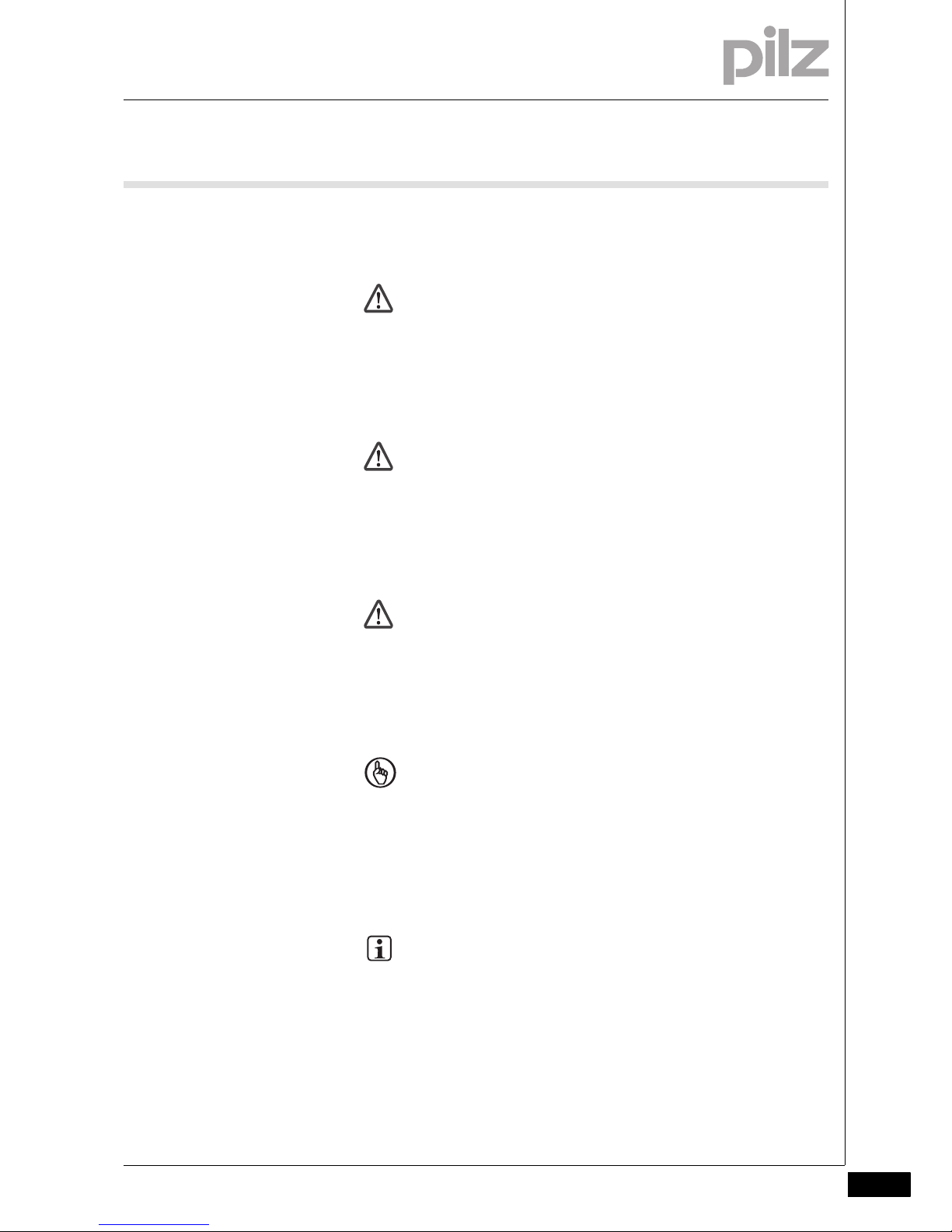
Information that is particularly important is identified as follows:
DANGER!
This warning must be heeded! It warns of a hazardous situation
that poses an immediate threat of serious injury and death and
indicates preventive measures that can be taken.
WARNING!
This warning must be heeded! It warns of a hazardous situation
that could lead to serious injury and death and indicates preventive measures that can be taken.
CAUTION!
This refers to a hazard that can lead to a less serious or minor
injury plus material damage, and also provides information on
preventive measures that can be taken.
NOTICE
This describes a situation in which the unit(s) could be damaged
and also provides information on preventive measures that can
be taken. It also highlights areas within the text that are of particular importance.
INFORMATION
This gives advice on applications and provides information on
special features.
Page 8

1 Introduction
Pilz GmbH & Co. KG, Felix-Wankel-Straße 2, 73760 Ostfildern, Germany
Telephone: +49 711 3409-0, Telefax: +49 711 3409-133, E-Mail: pilz.gmbh@pilz.de
1-4
Page 9

Pilz GmbH & Co. KG, Felix-Wankel-Straße 2, 73760 Ostfildern, Germany
Telephone: +49 711 3409-0, Telefax: +49 711 3409-133, E-Mail: pilz.gmbh@pilz.de
2-1
2.1 Unit structure
2 Overview
22000OverviewOverview2-2.1Unit structure2100Unit structure2-
2.1.1 Range
Range2-Eigenschaften
Base unit PNOZ mm0p
2.1.2 Unit features
Unit features2-Gerä temerkmale_Verwendung
Using the product PNOZ mm0p:
Verwendung/Bildunterschrift_multi_Basis
Base unit from the configurable control system PNOZmulti
Geraetemerkmale_Zusatz BA Einleitung
The product has the following features:
Gertemerkmale_multi_Mini_Basis
Can be configured in the PNOZmulti Configurator
Semiconductor outputs:
4 safety outputs
Depending on the application, up to PL e of EN ISO 13849-1 and up
to SIL CL 3 of EN IEC 62061
12 inputs for connecting:
– Emergency stop pushbuttons
– Two-Hand Button
– Safety gate limit switches
– Reset Element
– Light beam devices
– Scanners
– Enable Switch
– PSEN
– Operating Mode Selector Switch
8 configurable inputs/outputs
Can be configured as:
– Inputs (see above for connection options)
or
– Auxiliary outputs
4 configurable outputs
Can be configured as:
– Auxiliary outputs
or
– test pulse outputs
LED for:
– Error messages
– Diagnostics
– Supply voltage
– Output circuits
– Input circuits
Page 10

2.1 Unit structure
2 Overview
Pilz GmbH & Co. KG, Felix-Wankel-Straße 2, 73760 Ostfildern, Germany
Telephone: +49 711 3409-0, Telefax: +49 711 3409-133, E-Mail: pilz.gmbh@pilz.de
2-2
Display for:
– Error messages
– State of supply voltage
– State of inputs/outputs
– Status information
– Unit information
Monitors shorts across the inputs through test pulse outputs
Monitoring of shorts between the safety outputs
Plug-in connection terminals:
either spring-loaded terminal or screw terminal available as an accessory (see order reference)
Rotary knob for menu control
2.1.3 Chip card
Chip card2-Bestimmung/Gertebeschreibung_multi_Chipkarte
To be able to use the product you will need a chip card.
Chip cards are available with memories of 8 kByte and 32 kByte. For
large-scale projects we recommend the 32 kByte chip card (see Technical Catalogue). Accessories chapter).
Page 11

Pilz GmbH & Co. KG, Felix-Wankel-Straße 2, 73760 Ostfildern, Germany
Telephone: +49 711 3409-0, Telefax: +49 711 3409-133, E-Mail: pilz.gmbh@pilz.de
2-3
2.2 Front view
2 Overview
2.2Front view2200Front view2-Klemmenbelegung
Front view with and without cover
Legende__Klemmenbelegung _mini_multi_Basis_ BA
Key:
X1:
– Inputs I8 ... I15
X2:
– Configurable test pulse/auxiliary outputs T0M20 ... T3M23
– Semiconductor outputs O0 ... O3
X3:
– Configurable inputs/outputs IM0 – IM3
– Inputs I4 ... I7
X4:
– Configurable inputs/outputs IM16 – IM19
– Supply connections
LEDs:
–POWER
–RUN
– DIAG
–FAULT
–I FAULT
–O FAULT
X3
X1
X4
X2
PNOZ mm0p
IM0
IM1 IM2 I6
I5
I4IM3 I7
I8
I9 I10 I14
I13
I12I11 I15
X3
X1
X4
X2
PNOZ mm0p
T0
T1 T2 O2
O1
O0T3 O3
IM16
IM17 IM18 0 V
A2
A1IM19 24 V
M20
M21
M22 M23
IM0
IM1 IM2 I6
I5
I4IM3 I7
I8
I9 I10 I14
I13
I12I11 I15
T0
T1 T2 O2
O1
O0T3 O3
IM16
IM17 IM18 0 V
A2
A1IM19 24 V
M20
M21
M22 M23
Page 12

2 Overview
Pilz GmbH & Co. KG, Felix-Wankel-Straße 2, 73760 Ostfildern, Germany
Telephone: +49 711 3409-0, Telefax: +49 711 3409-133, E-Mail: pilz.gmbh@pilz.de
2-4
Page 13

Pilz GmbH & Co. KG, Felix-Wankel-Straße 2, 73760 Ostfildern, Germany
Telephone: +49 711 3409-0, Telefax: +49 711 3409-133, E-Mail: pilz.gmbh@pilz.de
3-1
3.1 Intended use
3 Safety
33000SafetySafety3-3.1Intended use3100Intended use3-Bestimmung/Gertebeschreibung_multi_System
The configurable control system PNOZmulti is used for the safety-related interruption of safety circuits and is designed for use in:
E-STOP equipment
Safety circuits in accordance with VDE 0113 Part 1 and EN 60204-1
Bestimmung/Gertebeschreibung_multi_Zusatz_Achtung_Standard-Ausgaenge_BA
Bestimmung/Gertebeschreibung_EMV+Ausschluss
Intended use includes making the electrical installation EMC-compliant.
The product is designed for use in an industrial environment. It is not
suitable for use in a domestic environment, as this can lead to interference.
The following is deemed improper use in particular:
Any component, technical or electrical modification to the product
Use of the product outside the areas described in this manual
Use of the product outside the technical details (see chapter entitled
“Technical Details”)
3.1.1 System requirements
System requirements3-Systemvoraussetzungen - Verweis auf Produktänderungen
Please refer to the "Product Modifications" document in the "Version
overview" section for details of which versions of the base unit and
PNOZmulti Configurator can be used for this product.
CAUTION!
Inputs and outputs for standard functions must not be used for
safety-related applications.
Page 14

3.2 Safety regulations
3 Safety
Pilz GmbH & Co. KG, Felix-Wankel-Straße 2, 73760 Ostfildern, Germany
Telephone: +49 711 3409-0, Telefax: +49 711 3409-133, E-Mail: pilz.gmbh@pilz.de
3-2
3.2Safety regulations3200Safety regulations3-
3.2.1 Use of qualified personnel
Use of qualified personnel3-Sich Qualif. Personal
The products may only be assembled, installed, programmed, commissioned, operated, maintained and decommissioned by competent persons.
A competent person is someone who, because of their training, experience and current professional activity, has the specialist knowledge required to test, assess and operate the work equipment, devices,
systems, plant and machinery in accordance with the general standards
and guidelines for safety technology.
It is the company's responsibility only to employ personnel who:
Are familiar with the basic regulations concerning health and safety /
accident prevention
Have read and understood the safety guidelines given in this descrip-
tion
Have a good knowledge of the generic and specialist standards ap-
plicable to the specific application.
3.2.2 Warranty and liability
Warranty and liability3-Sich Gewhrleistung
All claims to warranty and liability will be rendered invalid if:
The product was used contrary to the purpose for which it is intended
Damage can be attributed to not having followed the guidelines in the
manual
Operating personnel are not suitably qualified
Any type of modification has been made (e.g. exchanging compo-
nents on the PCB boards, soldering work etc.).
3.2.3 Disposal
Disposal3-Sich Ent sorgung
In safety-related applications, please comply with the mission time t
M
in the safety-related characteristic data.
When decommissioning, please comply with local regulations regard-
ing the disposal of electronic devices (e.g. Electrical and Electronic
Equipment Act).
Page 15

Pilz GmbH & Co. KG, Felix-Wankel-Straße 2, 73760 Ostfildern, Germany
Telephone: +49 711 3409-0, Telefax: +49 711 3409-133, E-Mail: pilz.gmbh@pilz.de
3-3
3.2 Safety regulations
3 Safety
3.2.4 For your safety
For your safety3-Zu Ihrer Sicherheit_mini_mult i_Basis
The unit meets all the necessary conditions for safe operation. However,
you should always ensure that the following safety requirements are
met:
Adequate protection must be provided for all inductive consumers.
Do not open the housing or make any unauthorised modifications.
Please make sure you shut down the supply voltage when performing
maintenance work (e.g. exchanging contactors).
Page 16

3 Safety
Pilz GmbH & Co. KG, Felix-Wankel-Straße 2, 73760 Ostfildern, Germany
Telephone: +49 711 3409-0, Telefax: +49 711 3409-133, E-Mail: pilz.gmbh@pilz.de
3-4
Page 17

Pilz GmbH & Co. KG, Felix-Wankel-Straße 2, 73760 Ostfildern, Germany
Telephone: +49 711 3409-0, Telefax: +49 711 3409-133, E-Mail: pilz.gmbh@pilz.de
4-1
4.1 Device properties
4 Function description
44000Function descriptionFunction description4-4.1Device properties4100Device properties4-
4.1.1 Integrated protection mechanisms
Integrated protection mechanisms4-Sicherheitseigenschaften_multi_allgemein
The relay conforms to the following safety criteria:
The circuit is redundant with built-in self-monitoring.
The safety function remains effective in the case of a component fail-
ure.
Sicherheitseigenschaften_Halbleiter
The safety outputs are tested periodically using a disconnection test.
4.1.2 Operation
Operation4-Funktionen_multi_Basis_ohne_Erweiterung
The function of the safety system's inputs and outputs depends on the
safety circuit created using the PNOZmulti Configurator. A chip card is
used to download the safety circuit to the base unit. The base unit has
2 microcontrollers that monitor each other. They evaluate the input circuits and switch the outputs accordingly.
The LEDs indicate the status of the PNOZmulti safety system.
The LC display indicates the status of the inputs/outputs and the supply
voltage.
The online help on the PNOZmulti Configurator contains descriptions of
the operating modes and all the functions of the PNOZmulti safety system, plus connection examples.
4.1.3 Block diagram
Block diagram4-Blockschaltbild
=
Power
A1 A2
=
Input
USB
IM1
I8I5
I11
I4 I9 I12 I13 I14 I15I7I6
I10
IM2I M0 I M3 IM16 IM18IM17 IM19
Configurable
input/output
Configurable
output
24 V 0 V
24 V
0 V
T0M21
O2
O0
O1
O3
T0M22 T0M23T0M20
Page 18

4.1 Device properties
4 Function description
Pilz GmbH & Co. KG, Felix-Wankel-Straße 2, 73760 Ostfildern, Germany
Telephone: +49 711 3409-0, Telefax: +49 711 3409-133, E-Mail: pilz.gmbh@pilz.de
4-2
4.1.4 Diagnostics
Diagnostics4-Funktionen_mini_mult i_Basis_Diagnose
The status and error messages displayed by the LEDs are saved in an
error stack. This error stack can be shown on the display or can be read
from the PNOZmulti Configurator via the USB port.
Page 19

Pilz GmbH & Co. KG, Felix-Wankel-Straße 2, 73760 Ostfildern, Germany
Telephone: +49 711 3409-0, Telefax: +49 711 3409-133, E-Mail: pilz.gmbh@pilz.de
5-1
5.1 Control cabinet installation
5 Installation
55000InstallationInstallation5-5.1Control cabinet installation51 00Control cabinet installation5-Montage_Sigma_allgemein
The unit should be installed in a control cabinet with a protection type
of at least IP54.
Use the notch on the rear of the unit to attach it to a mounting rail.
In environments exposed to heavy vibration or when installing on a
vertical mounting rail (35 mm), the unit should be secured using a fixing element (e.g. retaining bracket or end angle).
Push the unit upwards or downwards before lifting it from the mount-
ing rail.
Montage_EMV ESD
5.1.1 Dimensions
Dimensions5-Abmessungen
*with spring-loaded terminals
CAUTION!
Damage due to electrostatic discharge!
Electrostatic discharge can damage components. Ensure
against discharge before touching the product, e.g. by touching
an earthed, conductive surface or by wearing an earthed armband.
120 (4.72")
* 100 (3,94")
98 (3.86")
45
(1.77")
Page 20

5.1 Control cabinet installation
5 Installation
Pilz GmbH & Co. KG, Felix-Wankel-Straße 2, 73760 Ostfildern, Germany
Telephone: +49 711 3409-0, Telefax: +49 711 3409-133, E-Mail: pilz.gmbh@pilz.de
5-2
5.1.2 Mounting distances
Mounting distances5-][Montage_multi_Montageabstaende-ohne-Erweiterung
With control cabinet installation it is essential to maintain a certain distance from the top and bottom, as well as to other heat-producing devices (see diagram). The values stated for the mounting distances are
minimum specifications.
The ambient temperature of the product in the control cabinet must not
exceed the figure stated in the technical details, otherwise air conditioning will be required.
Mounting distances:
30 mm
(1.181")
30 mm
(1.181")
20 mm
(0.787")
20 mm
(0.787")
IM0
IM1 IM2 I6I5I4IM3 I7
I8
I10 I14
I13
I12I11 I15
X3
X1
X4
X2
PNOZ mm0.1p
T0
T1 T2 O2
O1
O0T3 O3
IM16
IM17 IM18 0 V
A2
A1IM19 24 V
M20
M21
M22 M23
Heat-producing device
Heat-producing device
Page 21

Pilz GmbH & Co. KG, Felix-Wankel-Straße 2, 73760 Ostfildern, Germany
Telephone: +49 711 3409-0, Telefax: +49 711 3409-133, E-Mail: pilz.gmbh@pilz.de
6-1
6.1 General wiring guidelines
6 Commissioning
66000CommissioningCommissioning6-6.1Genera l wiring guidelines6100General wiring guide lines6-Verdrahtung_mini_multi_HL_Ausg
The wiring is defined in the circuit diagram in the Configurator. There you
can select the inputs that are to perform a safety function and the outputs that are to switch this safety function.
Note:
Information given in the "Technical details" must be followed.
Outputs O0 to O3 are semiconductor outputs
Use copper wire that can withstand 75 °C.
Sufficient fuse protection must be provided on all output contacts
with inductive loads.
The safety system and input circuits must always be supplied by a
single power supply. The power supply must meet the regulations for
extra low voltages with safe separation.
Test pulse outputs must exclusively be used to test the inputs. They
must not be used to drive loads.
Do not route the test pulse lines together with actuator cables within
an unprotected multicore cable.
Page 22

6.2 Preparing for operation
6 Commissioning
Pilz GmbH & Co. KG, Felix-Wankel-Straße 2, 73760 Ostfildern, Germany
Telephone: +49 711 3409-0, Telefax: +49 711 3409-133, E-Mail: pilz.gmbh@pilz.de
6-2
6.2Preparing for operation6200Preparing for operation6-
6.2.1 Function test during commissioning
Function test during commissioning6-Verdrahtung_multi_Basis_Betr_Funktionstest_BA
6.2.2 Using the chip card
Using the chip card 6-Inbetriebnahme_Chipkarte_einsetzen_1_wichtig_Kontaktflaeche_sauber
Inbetriebnahme_Chipkarte_einsetzen_2_wichtig_produkt_ausschalten
Inbetriebnahme_Chipkarte_einsetzen_3_Chipkarte_nicht verkantet
Make sure that you do not bend the chip card as you insert it into the
chip card slot.
Inbetriebnahme_Chipkarte_einsetzen_4_Chipkarte_nicht verkantet_Bild_multi_mini
CAUTION!
It is essential to check that the safety devices operate correctly
after the chip card has been exchanged
after a project has been downloaded
when the project has been deleted from the base unit's mem-
ory ("Reset Project" menu)
NOTICE
The chip card contact is only guaranteed if the contact surface is
clean and undamaged. For this reason please protect the chip
card's contact surface from
Contamination
Contact
Mechanical impact, such as scratches.
NOTICE
Switch off the product before inserting or exchanging the chip
card.
Page 23

Pilz GmbH & Co. KG, Felix-Wankel-Straße 2, 73760 Ostfildern, Germany
Telephone: +49 711 3409-0, Telefax: +49 711 3409-133, E-Mail: pilz.gmbh@pilz.de
6-3
6.2 Preparing for operation
6 Commissioning
6.2.3 Commissioning the PNOZmulti safety system
Commissioning the PNOZmulti safety system6-Verdrahtung_multi_Basis_Betr_erstes_Mal_mini_multi_BA
Procedure:
Wire the inputs and outputs on the base unit in accordance with the
circuit diagram.
Connect the supply voltage:
– Supply voltage for the units:
– Terminal A1: + 24 VDC
–Terminal A2: 0 V
– Supply voltage for the semiconductor outputs:
– 24 V terminal: + 24 VDC
– 0V terminal: 0 V
Note: The supply voltage for the semiconductor outputs must always be
present, even if you are not using the semiconductor outputs.
6.2.3.1 Load project from chip card
Load project from chip card6-Verdrahtung_mini_multi_Basis_Betr_erstes_Mal_von_Chipkarte_BA
Procedure:
Insert the chip card containing the current project into the card slot on
the base unit.
Switch on the supply voltage. The LC display shows the project
name, CRC sum and the date the project was created. Please check
this information.
Load the project by pressing the rotary knob. For the project to be
downloaded, the rotary knob must be held down for between 3 and 8
seconds. Once the project has been successfully downloaded, the
status of the inputs and outputs will be shown on the display.
6.2.3.2 Load project via USB port
Load project via USB port 6-Verdrahtung_mini_multi_Basis_Betr_erstes_Mal_USB_BA
Procedure:
Insert a chip card into the card slot on the base unit.
Connect the computer containing the PNOZmulti Configurator to the
base unit via the USB port.
Switch on the supply voltage.
Download the project (see PNOZmulti Configurator's online help).
Once the project has been successfully downloaded, the status of the
inputs and outputs and the supply voltage will be shown on the display. The "RUN" LED will be lit.
Page 24

6.2 Preparing for operation
6 Commissioning
Pilz GmbH & Co. KG, Felix-Wankel-Straße 2, 73760 Ostfildern, Germany
Telephone: +49 711 3409-0, Telefax: +49 711 3409-133, E-Mail: pilz.gmbh@pilz.de
6-4
6.2.4 Connection
Connection6-Betriebsbereitschaft_herstellen_multi-mini Basisgerät
Supply voltage
Connection examples for the input circuit
Supply voltage AC DC
For the safety system
For the semiconductor outputs
Must always be present, even if the
semiconductor outputs are not used
Input circuit Single-channel Dual-channel
E-STOP
without detection of shorts across
contacts
E-STOP
with detection of shorts across contacts
A1
+ 24 V DC
A2
0 V
24 V
+ 24 V DC
0 V
0 V
S1
IM0
L+
S1
IM1
IM0
L+
L+
IM0
T0M20
S1
S1
T1M21
IM1
T0M20
IM0
Page 25

Pilz GmbH & Co. KG, Felix-Wankel-Straße 2, 73760 Ostfildern, Germany
Telephone: +49 711 3409-0, Telefax: +49 711 3409-133, E-Mail: pilz.gmbh@pilz.de
6-5
6.2 Preparing for operation
6 Commissioning
Connection examples for reset circuit
Connection examples for semiconductor outputs
*Two loads may be connected to each safety output with advanced fault
detection, even on applications in accordance with EN IEC 62061, SIL
CL 3. Prerequisite: Feedback loop is connected, shorts across contacts
and external power sources are excluded (e.g. through separate multicore cables). Please note that, in the event of an error in the feedback
loop, the safety system switches to a safe condition and shuts down all
the outputs.
Reset circuit Input circuit without detection of
shorts across contacts
Input circuit with detection of shorts
across contacts
Redundant output
Single output
Single output with advanced fault detection*
I5
S3
L+
I5
T0M20
S3
K2
L-
O0 (O2)
O1 (O3)
K1
L-
K3
L-
K4
O0 (O2)
O1 ( O3)
K1
L-
K2
K1
L+
L-
K2
O0 (O2)
IM0
Page 26

6.2 Preparing for operation
6 Commissioning
Pilz GmbH & Co. KG, Felix-Wankel-Straße 2, 73760 Ostfildern, Germany
Telephone: +49 711 3409-0, Telefax: +49 711 3409-133, E-Mail: pilz.gmbh@pilz.de
6-6
Connection examples for feedback loop
Feedback loop Redundant output
Contacts from external contactors
K1
L+
L-
K2
O0 (O2, O4)
O1 (O3, O5)
IM0
L-
Page 27

Pilz GmbH & Co. KG, Felix-Wankel-Straße 2, 73760 Ostfildern, Germany
Telephone: +49 711 3409-0, Telefax: +49 711 3409-133, E-Mail: pilz.gmbh@pilz.de
6-7
6.3 Connection example
6 Commissioning
6.3Connection example6300Connection example6-Anschlussbeispiel_Basisgeräte_mini_BA
Dual-channel E-STOP and safety gate wiring, monitored reset (IM18),
feedback loop (IM16)
IM0
IM1
IM2
IM3I4I5I6I7
I8I9I10
I11
I12
I13
I14
I15
IM16
IM17
IM18
IM19
T0
M20T1M21T2M22T3M23
O0O1O2
O3
A1
A2
24V
0V
K1
K2
S1
K2
K1
S2
S3
L+
L-
Page 28

6 Commissioning
Pilz GmbH & Co. KG, Felix-Wankel-Straße 2, 73760 Ostfildern, Germany
Telephone: +49 711 3409-0, Telefax: +49 711 3409-133, E-Mail: pilz.gmbh@pilz.de
6-8
Page 29

Pilz GmbH & Co. KG, Felix-Wankel-Straße 2, 73760 Ostfildern, Germany
Telephone: +49 711 3409-0, Telefax: +49 711 3409-133, E-Mail: pilz.gmbh@pilz.de
7-1
7.1 Rotary knob
7 Operation
77000OperationOperation7-7.1Rota ry knob7100Rotary kno b7-
7.1.1 Function
Function7-Inbetriebnahme_Drehknopf_Funktion
The menu settings are made on the unit's display via a rotary knob. You
have the option to make the settings on the knob by hand or with a
screwdriver. If you make the settings with a screwdriver, the knob can
remain within the unit.
7.1.2 Pull out and retract the knob
Pull out and retract the knob 7-Inbetriebnahme_Drehknopf_Bild
Inbetriebnahme_Drehknopf_Funktion_heraus_und_zurck
The rotary knob:
(A) should be pulled out until it clicks into position
(B) then released and retracted back into the unit:
– Press the latch on the side of the rotary knob (1) towards the centre
of the knob. This releases the rotary knob.
– Press the knob downwards (2) while keeping the latch held down.
7.1.3 Rotate and press the knob
Rotate and press the knob 7-Inbetriebnahme_Drehknopf_Funktion_drcken_drehen_anzeigen
The settings are made via the rotary knob, as follows:
Press the knob
Confirm selection/setting
Switch to menu
Rotate knob
Select menu level
A
1.
2.
B
Page 30

7.2 Messages
7 Operation
Pilz GmbH & Co. KG, Felix-Wankel-Straße 2, 73760 Ostfildern, Germany
Telephone: +49 711 3409-0, Telefax: +49 711 3409-133, E-Mail: pilz.gmbh@pilz.de
7-2
7.2Messages7200Messages7-Betrieb_M eldungen_Basis_BA
The PNOZmulti control system is ready for operation when the "POWER" and "RUN" LEDs on the base unit are lit continuously.
7.2.1 Display elements
Display elements7-
7.2.1.1 Status indicators
Status indicators7-Anzeige Legende 3x
Legend:
7.2.1.2 Display elements for device diagnostics
Display elements for device diagnostics7-Betrieb_Anzeige_mini_mult i_mm0p_BA
LED on
LED flashes
LED off
Base Error
RUN
DIAG
FAULT
IFAULT
OFAULT
The existing user program has been deleted.
External error on the base unit, leading to a safe condition, e.g. chip card not inserted
External error on the base unit outputs, e.g. short across the contacts, leading to a
safe condition.
Internal error on the base unit
Internal error on the base unit (inputs)
Internal error on the base unit (outputs)
Base unit in a STOP condition
External error on the base unit inputs, which does not lead to a safe condition, e.g.
partially operated
External error on the base unit outputs, which does not lead to a safe condition,
e.g. feedback input defective
Page 31

Pilz GmbH & Co. KG, Felix-Wankel-Straße 2, 73760 Ostfildern, Germany
Telephone: +49 711 3409-0, Telefax: +49 711 3409-133, E-Mail: pilz.gmbh@pilz.de
7-3
7.2 Messages
7 Operation
7.2.1.3 Display
Display7-Betrieb_Display_mini_multi_B A
The LC display has four lines. It displays information and navigates the
menu:
Display Example Description
RUN
State of inputs/outputs and supply
voltage
The lines are assigned terminals X1 ...
X4
State:
ERROR
Status and error messages
Line 1 ... 4: Status and error messages
as short text.
DISPLAY MESSAGE
Display messages
Line 1 ... 4: Customised messages that
are created in the PNOZmulti Configurator.
PROJECT INFO
Project information
1. Line: Project name
2. Line: Project name
3. Line: CRC sum (CRC)
4. Line: Creation date
IP ADDRESS
IP address of base unit
(only appears on base units to which a
communication module with Ethernet
interface is connected)
1. Line: Project name
2. Line: Project name
3. Line: CRC sum (CRC)
4. Line: Creation date
INT. SAFE LINK
Internal interface for connection of two
base units
(only appears on devices with an integrated interface for connection of two
base units)
1. Line: Name of interface
2. Line: Interface connected yes/no
3.-4. Line: Configured cable length
(100 m/1000 m)
DEVICE INFO
Device information
1. Line: Operating hours since initial
commissioning (H)
2. Line: Software version (SW)
3. Line: Hardware version (HW)
4. Line: Serial number of PNOZ mm0p
(SN)
X3
X1
X2
X4
T
T
M
Input active
Input inactive
Semiconductor output active
Semiconductor output inactive
Test pulse output
Message is present
Error message is present
T
M
E
Display in the event of a message (bottom
Feedback
loop
E-STOP
pressed
PNOZ mm0p
project
CRC: 0x8108
09.02.2009
IP Address
169.254.60.1/16
Int. Safe Link
connected: yes
cable length:
max. 100 m
H 00000000003
HW 0x007
SW 0x0000
SN 0x000000009
Page 32

7.2 Messages
7 Operation
Pilz GmbH & Co. KG, Felix-Wankel-Straße 2, 73760 Ostfildern, Germany
Telephone: +49 711 3409-0, Telefax: +49 711 3409-133, E-Mail: pilz.gmbh@pilz.de
7-4
You can switch between the menu levels by pressing or rotating the
knob.
SHOW ERROR STACK
Show error stack
Shows the error stack entries
ERROR STACK
Error stack entries
1. Line: Sequential number
2. Line: Error class (EC) and error information (EI)
3. Line: Error number (EN) and error
parameter (PA)
4. Line: Continuation of error parameter (PA)
INTERFACE
interface
(only appears on base units to which a
communication module is connected)
Show selected interface /
on expandable base units:
Select interface
STOP Device?
Stop device
Bring device to a STOP condition
RESET PROJECT?
Delete project
Delete project from the base unit's
memory
EXIT MENU?
Exit menu
Exit menu
Display Example Description
SHOW
ERROR
STACK
1/64
EN: 01
EC: 02
FF 00 00 00
EI: 12
PA: 09
Interface
USB
STOP Device?
RESET
PROJECT?
EXIT
MENU?
Page 33

Pilz GmbH & Co. KG, Felix-Wankel-Straße 2, 73760 Ostfildern, Germany
Telephone: +49 711 3409-0, Telefax: +49 711 3409-133, E-Mail: pilz.gmbh@pilz.de
7-5
7.2 Messages
7 Operation
7.2.1.4 Switch between menu levels
Switch between menu levels 7-Betrieb_Display_Funktionsübersicht
Schematic representation of the menu functions
1) Further information on error messages can be found under "Unit diagnostics on the LC display"
2) Further information on the error stack can be found under "Error stack
on the LC display"
ERROR
PROJECT
INFO
DEVICE
INFO
SHOW
ERROR
STACK?
EXIT
MENU?
ERROR
STACK
RUN
NEXT
ERROR
STACK
1)
2)
RESET
PROJECT?
...
RUN
...
INTERFACE
...
STOP
DEVICE?
...
2 s
4 s
4 s
DISPLAY
MESSAGE
NEXT
DISPLAY
MESSAGE
...
Page 34

7.2 Messages
7 Operation
Pilz GmbH & Co. KG, Felix-Wankel-Straße 2, 73760 Ostfildern, Germany
Telephone: +49 711 3409-0, Telefax: +49 711 3409-133, E-Mail: pilz.gmbh@pilz.de
7-6
7.2.1.5 Unit diagnostics on the LC display
Unit diagnostics on the LC display7-Betrieb_Display_Dia gnose
Procedure for showing error messages on the LC display, when the errors do not lead to a safe condition:
Use the rotary knob to display stored errors:
* If an error leads to a safe condition, the error message appears on the
display immediately. Once the cause has been rectified, you will need to
reset the unit
Procedure for resetting the unit:
Press the rotary knob for between 3 and 8 seconds to reset the unit.
Error messages Errors
FAULTY PROJECT Chip card contains a project which is faulty or incompati-
ble.
CHIP CARD ? Chip card is not inserted, blank or unreadable
FAULTY TEST PULSE Error caused by test pulse
PARTIALLY OPERATED Function element was or is partially operated
FEED BACK LOOP Exernal error at the feedback loop inputs
OPERATING MODE SWITCH SELECTOR Error on the operating mode selector switch function ele-
ment
FAULTY OUTPUT External error on the output
OUTPUT WITH ADVANCED FAULT DETECTION External error on the output with advanced fault detection
LOAD SUPPLY Error in the supply voltage for the semiconductor outputs
FAULTY DEVICE Internal error on the base unit.
SUPPLY LOW Supply voltage is below the tolerance level
SUPPLY HIGH Supply voltage exceeds the tolerance level
RELAY DEVICE? Error on the expansion module with relay outputs
RELAY DEVICE OR TERMINATION PLUG? Error on the expansion module with relay outputs or on the
connector
Output
faulty
*
X3
X1
X2
X4
T
T
M
Page 35

Pilz GmbH & Co. KG, Felix-Wankel-Straße 2, 73760 Ostfildern, Germany
Telephone: +49 711 3409-0, Telefax: +49 711 3409-133, E-Mail: pilz.gmbh@pilz.de
7-7
7.2 Messages
7 Operation
7.2.1.6 Error stack on the LC display
Error stack on the LC display7-Betrieb_Display_erweiterte_Diagnose
The error stack can be read from the PNOZmulti Configurator or shown
on the LC display. The error stack helps Pilz technical support with fault
diagnostics. The error stack can store up to 64 status and error messages.
The following information is shown on the LC display:
Sequential number of an error stack entry. A new error stack entry is
stored in first place.
Error class (EC) and error information (EI)
Error number (EN) and five error parameters (PA)
Procedure for displaying the error stack on the LC display:
Use the rotary knob to display the error stack.
Procedure for reading the error stack with the PNOZmulti Configurator:
See online help for the PNOZmulti Configurator
INFORMATION
Use the rotary knob to exit the error stack.
01/64
EN: 01
EC: 02
FF 00 00 00
EI: 12
PA: 09
PNOZ mm0p
CRC: 0x8108
project
09.02.2009
H 00000000003
HW 0x07
SW 0x0000
SN 0x000000006
Show
error stack?
X3
X1
X2
X4
T
T
M
Page 36

7 Operation
Pilz GmbH & Co. KG, Felix-Wankel-Straße 2, 73760 Ostfildern, Germany
Telephone: +49 711 3409-0, Telefax: +49 711 3409-133, E-Mail: pilz.gmbh@pilz.de
7-8
Page 37

Pilz GmbH & Co. KG, Felix-Wankel-Straße 2, 73760 Ostfildern, Germany
Telephone: +49 711 3409-0, Telefax: +49 711 3409-133, E-Mail: pilz.gmbh@pilz.de
8-1
8.1 Technical details
8 Technical Details
88000Technical DetailsTechnical Details8-8.1Technical details8100Technical details8-][Technische Daten_multi_Basis_Mini
Technical details
Electrical data
Supply voltage UB DC 24 V
Voltage tolerance -15 %/+20 %
Power consumption at U
B
DC
without load 8.0 W
with load 35.0 W
Residual ripple DC 5 %
Status display Display, LED
Times
Switch-on delay 5.00 s
Simultaneity channel 1/2/3 3 s
Two-hand circuit 0.5 s
Supply interruption before de-energisation 20 ms
Inputs
Number 12
Voltage and current at input, reset and feedback circuit 24.0 V, 5.0 mA
Galvanic isolation no
Signal level at "0" -3 - +5 V DC
Signal level at "1" 15 - 30 V DC
Min. pulse duration 16 ms
Pulse suppression 0.6 ms
Maximum input delay 4 ms
Test pulse outputs
Number of test pulse outputs 4
Voltage and current, 24 V 0.1 A
Off time during self test 5 ms
Galvanic isolation no
Short circuit-proof yes
Semiconductor outputs
Number 4
Switching capability
voltage 24 V
current 2 A
power 48 W
Max. capacitive load 1 µF
External supply voltage 24.0 V
Voltage tolerance -15 %/+20 %
Max. duration of off time during self test 330 µs
Galvanic isolation yes
Short circuit-proof yes
Switch-off delay 30 ms
Residual current at "0" 0.5 mA
Signal level at "1" UB - 0.5 V DC bei 2 A
Configurable inputs/outputs (inputs or auxiliary outputs)
Number 8
Galvanic isolation no
Page 38

8.1 Technical details
8 Technical Details
Pilz GmbH & Co. KG, Felix-Wankel-Straße 2, 73760 Ostfildern, Germany
Telephone: +49 711 3409-0, Telefax: +49 711 3409-133, E-Mail: pilz.gmbh@pilz.de
8-2
Inputs
Voltage on the input circuit 24.0 V
Current on the input circuit 5 mA
Signal level at "0" -3 ... +5 V DC
Signal level at "1" 15 ... 30 V DC
Max. filter time 4.0 ms
Min. pulse duration 16 ms
Pulse suppression 0.6 ms
Auxiliary outputs
Voltage 24.0 V
Current 75 mA
Power 1.8 W
Short circuit-proof yes
Residual current at "0" 0.5 mA
Voltage at “1” UB - 2 V bei 0.1 A
Environmental data
Ambient temperature 0 - 60 °C
Storage temperature -25 - 70 °C
Climatic suitability in accordance with EN 60068-2-30,
EN 60068-2-78
93 % r. h. at 40 °C
Condensation not permitted
EMC EN 61131-2
Vibration to EN 60068-2-6
Frequency 10 - 150 Hz
Max. acceleration 1g
Airgap creepage in accordance with EN 61131-2
Overvoltage category II
Pollution degree 2
Rated insulation voltage 30 V
Rated impulse withstand voltage 2.50 kV
Shock stress
EN 60068-2-27 15g
11 ms
EN 60068-2-29 25g
6 ms
Mechanical data
Protection type
Mounting (e.g. cabinet) IP54
Housing IP20
Terminals IP20
DIN rail
Top hat rail 35 x 7.5 EN 50022
Recess width 27 mm
Maximum cable runs
per input 1.0 km
Sum of individual cable runs at the test pulse output 2 km
Housing material
Housing PC
Front PC
Configurable inputs/outputs (inputs or auxiliary outputs)
Page 39

Pilz GmbH & Co. KG, Felix-Wankel-Straße 2, 73760 Ostfildern, Germany
Telephone: +49 711 3409-0, Telefax: +49 711 3409-133, E-Mail: pilz.gmbh@pilz.de
8-3
8.1 Technical details
8 Technical Details
Si-Kennzahlen_alle
Si_Kennzahlen_Erläuterung_1
All the units used within a safety function must be considered when calculating the safety characteristic data.
Technische Daten_Satz No rmen
The standards current on 2010-08 apply.
Cross section of external conductors with screw terminals
Power supply, inputs, auxiliary output, semiconductor outputs, test pulse outputs, cascading outputs:
1 core flexible 0.25 - 2.50 mm² , 24 - 12 AWG
2 core, same cross section, flexible:
without crimp connectors or with TWIN crimp connectors 0.20 - 1.50 mm² , 24 - 16 AWG
Torque setting with screw terminals 0.50 Nm
Cross section of external conductors with spring-loaded
terminals: Flexible with/without crimp connectors
0.20 - 2.50 mm² , 24 - 12 AWG
Spring-loaded terminals: Terminal points per connection 2
Stripping length 9 mm
Dimensions
Height 100.0 mm
Width 45.0 mm
Depth 120.0 mm
Weight 226 g
Safety characteristic data
Unit Operating mode EN ISO 13849-
1: 2006
PL
EN 954-1
Category
EN IEC 62061
SIL CL
PFH [1/h] EN ISO
13849-1:
2006
T
M
[year]
Logic
CPU PL e (Cat. 4) Cat. 4 SIL CL 3 1.54E-09 20
Input
SC inputs single-channel PL d (Cat. 2) Cat. 3 SIL CL 2 3.95E-09 20
SC inputs dual-channel PL e (Cat. 4) Cat. 4 SIL CL 3 4.61E-10 20
SC inputs light beam device PL e (Cat. 4) Cat. 4 SIL CL 3 3.95E-10 20
Output
SC outputs single-channel with
advanced fault detection
PL e (Cat. 4) Cat. 4 SIL CL 3 7.65E-10 20
SC outputs single-channel PL d (Cat. 2) Cat. 3 SIL CL 2 8.90E-10 20
SC outputs dual-channel PL e (Cat. 4) Cat. 4 SIL CL 3 7.86E-10 20
Mechanical data
Page 40

8.2 Maximum capacitive load C (µF) with load current I (A) at
the semiconductor outputs
8 Technical Details
Pilz GmbH & Co. KG, Felix-Wankel-Straße 2, 73760 Ostfildern, Germany
Telephone: +49 711 3409-0, Telefax: +49 711 3409-133, E-Mail: pilz.gmbh@pilz.de
8-4
8.2Maximum capacitive load C (μF) with load current I (A) at the semiconductor outputs8200Maximum capacitive load C (μF) with load current I (A) at the semiconductor outputs8-Kapazitive Last
4
8
12
16
20
0
0,2 0,4 0.6 0,8 1 1,2 1,4 1,6 1,8 2
I [A]
C [µF]
Page 41

Pilz GmbH & Co. KG, Felix-Wankel-Straße 2, 73760 Ostfildern, Germany
Telephone: +49 711 3409-0, Telefax: +49 711 3409-133, E-Mail: pilz.gmbh@pilz.de
8-5
8.3 Maximum permitted total current of the semiconductor
outputs
8 Technical Details
8.3Maximum permitted total c urrent of the semi conductor outputs8300Maximum perm itted total current of the semiconduct or outputs8-Maximal zulässiger Summenstrom der Halbleiterausgänge
I
Cfg
: Total current of the configurable semiconductor outputs (auxiliary
outputs)
I
HL
: Total current: Semiconductor outputs (safety outputs)
100
200
300
400
0
123456 78
IHL [A]
ICfg[mA]
0
Page 42

8.4 Order reference
8 Technical Details
Pilz GmbH & Co. KG, Felix-Wankel-Straße 2, 73760 Ostfildern, Germany
Telephone: +49 711 3409-0, Telefax: +49 711 3409-133, E-Mail: pilz.gmbh@pilz.de
8-6
8.4Order reference8400Order reference8-Best elldaten PNOZ mm0p
Bestelldaten Zubehör PNOZ mm0/0.1/0.2p
Bestelldaten Zubehör Kabel PNOZ mm0/0.1p
Order reference
Product type Features Order no.
PNOZ mm0p Base unit 772 000
Order reference: Accessories
Product Type Features Order no.
PNOZ s Set1 spring-loaded
terminals
1 set of spring-loaded terminals 751 008
PNOZ s Set1 screw terminals
1 set of screw terminals 750 008
Order reference: Cable
Product Type Features Order no.
PSSu A USB-CAB03 Mini USB cable, 3 m 312 992
PSSu A USB-CAB05 Mini USB cable, 5 m 312 993
Page 43

...
1001274-EN-04, 2011-10 Printed in Germany
© Pilz GmbH & Co. KG, 2011
+49 711 3409-444
support@pilz.com
Pilz GmbH & Co. KG
Felix-Wankel-Straße 2
73760 Ostfildern, Germany
Telephone: +49 711 3409-0
Telefax: +49 711 3409-133
E-Mail: pilz.gmbh@pilz.de
Internet: www.pilz.com
Technical support
In many countries we are
represented by our subsidiaries
and sales partners.
Please refer to our homepage
for further details or contact our
headquarters.
InduraNET p
®
, Pilz
®
, PIT
®
, PMCprotego
®
, PMI
®
, PNOZ
®
, Primo
®
, PSEN
®
, PSS
®
, PVIS
®
, SafetyBUS p
®
, SafetyEYE
®
, SafetyNET p
®
, the spirit of safety
®
are registered and protected trademarks
of Pilz GmbH & Co. KG in some countries. We would point out that product features may vary from the details stated in this document, depending on the status at the time of publication and the scope
of the equipment. We accept no responsibility for the validity, accuracy and entirety of the text and graphics presented in this information. Please contact our Technical Support if you have any questions.
Contact address
 Loading...