

Page 1

Operating Manual — No. 1001642-EN-03
PNOZmulti Modular Safety System
PNOZ ml2p
Page 2

This document is a translation of the original document.
All rights to this documentation are reserved by Pilz GmbH & Co. KG. Copies may be made
for internal purposes.
Suggestions and comments for improving this documentation will be gratefully received.
Pilz®, PIT®, PMI®, PNOZ®, Primo®, PSEN®, PSS®, PVIS®, SafetyBUS p®, SafetyEYE®,
SafetyNET p®, the spirit of safety® are registered and protected trademarks of
Pilz GmbH & Co. KG in some countries.
SD means Secure Digital.
Page 3

Pilz GmbH & Co. KG, Felix-Wankel-Straße 2, 73760 Ostfildern, Germany
Telephone: +49 711 3409-0, Telefax: +49 711 3409-133, E-Mail: pilz.gmbh@pilz.de
1
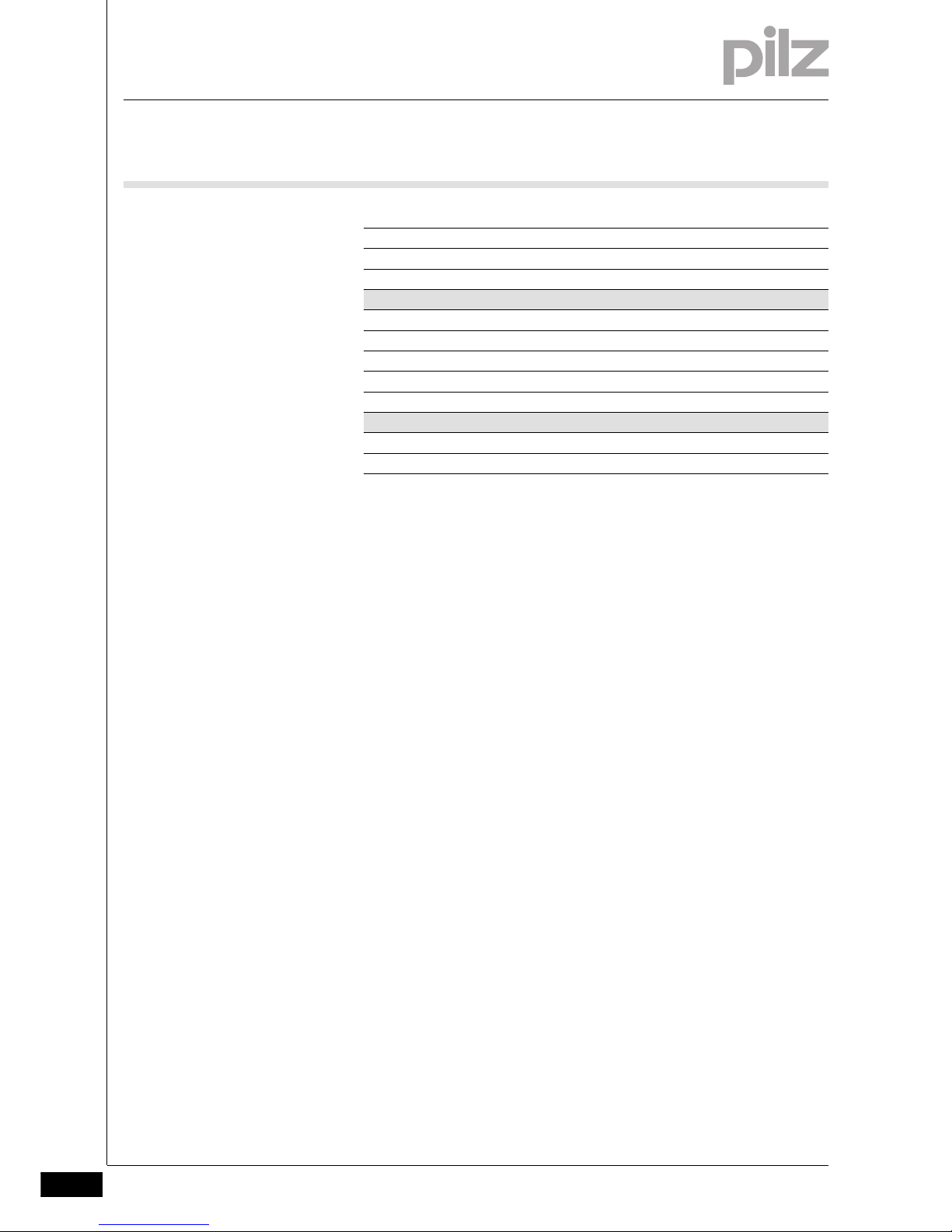
Contents
Contents
Contents Page
Chapter 1 Introduction
1.1 Validity of documentation 1-1
1.1.1 Retaining the documentation 1-1
1.2 Overview of documentation 1-2
1.3 Definition of symbols 1-3
Chapter 2 Overview
2.1 Unit structure 2-1
2.1.1 Scope of supply 2-1
2.1.2 Unit features 2-1
2.2 Front view 2-2
Chapter 3 Safety
3.1 Intended use 3-1
3.2 System requirements 3-2
3.3 Safety regulations 3-3
3.3.1 Use of qualified personnel 3-3
3.3.2 Warranty and liability 3-3
3.3.3 Disposal 3-3
3.3.4 For your safety 3-4
Chapter 4 Function description
4.1 Device properties 4-1
4.1.1 Integrated protection mechanisms 4-1
4.1.2 Function description 4-1
4.1.2.1 Operation 4-1
4.1.2.2 Block diagram 4-2
Chapter 5 Installation
5.1 General installation guidelines 5-1
5.1.1 Dimensions 5-1
5.2 Connecting the base unit and expansion
modules
5-2
Chapter 6 Commissioning
6.1 General wiring guidelines 6-1
6.1.1 Insulation voltage test 6-1
6.2 Preparing for operation 6-2
6.2.1 Download modified project to the PNOZmulti safety system
6-2
6.2.2 Connection 6-2
6.3 Series connection of 4 decentralised modules
6-3
Page 4
Contents
Pilz GmbH & Co. KG, Felix-Wankel-Straße 2, 73760 Ostfildern, Germany
Telephone: +49 711 3409-0, Telefax: +49 711 3409-133, E-Mail: pilz.gmbh@pilz.de
2
6.4 Voltage drop 6-4
6.4.1 Guidelines for various cable types 6-4
6.4.2 Calculation example 6-5
Chapter 7 Operation
7.1 Messages 7-1
7.2 Display elements 7-2
7.2.1 Display elements for device diagnostics 7-2
7.3 Fault detection 7-3
Chapter 8 Technical Details
8.1 Technical Details 8-1
8.2 Order reference 8-3
Page 5

Pilz GmbH & Co. KG, Felix-Wankel-Straße 2, 73760 Ostfildern, Germany
Telephone: +49 711 3409-0, Telefax: +49 711 3409-133, E-Mail: pilz.gmbh@pilz.de
1-1
1.1 Validity of documentation
1 Introduction
11000IntroductionIntroduction1-1.1Validity of documen tation1100Validity of documentati on1-Einf Gltigkeit der Dokumentation
This documentation is valid for the product PNOZ ml2p. It is valid until
new documentation is published.
Einf Einleitung
This operating manual explains the function and operation, describes
the installation and provides guidelines on how to connect the product .
1.1.1 Retaining the documentation
Retaining the documentation1-Einf Aufbewahren
This documentation is intended for instruction and should be retained
for future reference.
Page 6

1.2 Overview of documentation
1 Introduction
Pilz GmbH & Co. KG, Felix-Wankel-Straße 2, 73760 Ostfildern, Germany
Telephone: +49 711 3409-0, Telefax: +49 711 3409-133, E-Mail: pilz.gmbh@pilz.de
1-2
1.2Overview of documentation1200Overview of documentation1-Einf_Uebersicht_über_die_Doku_6_Inbetriebnahme
1 Introduction
The introduction is designed to familiarise you with the contents, structure and specific order of this manual.
2 Overview
This chapter provides information on the product's most important features.
3 Safety
This chapter must be read as it contains important information on safety
and intended use.
4 Function Description
This chapter describes the product's mode of operation.
5 Installation
This chapter explains how to install the product.
6 Commissioning
This chapter describes the product's commissioning and wiring.
7 Operation
This chapter describes how to operate the product and gives tips in the
case of a fault.
8 Technical Details
This chapter contains the product's technical details and order reference.
Page 7
Pilz GmbH & Co. KG, Felix-Wankel-Straße 2, 73760 Ostfildern, Germany
Telephone: +49 711 3409-0, Telefax: +49 711 3409-133, E-Mail: pilz.gmbh@pilz.de
1-3
1.3 Definition of symbols
1 Introduction
1.3Definition of symbols1300Definition of symbols1-Einfhrung Zeichen
Information that is of particular importance can be identified as follows:
DANGER!
This warning must be heeded! It warns of a hazardous situation
that poses an immediate threat of serious injury and death and
indicates preventive measures that can be taken.
WARNING!
This warning must be heeded! It warns of a hazardous situation
that could lead to serious injury and death and indicates preventive measures that can be taken.
CAUTION!
This refers to a hazard that can lead to a less serious or minor
injury plus material damage, and also provides information on
preventive measures that can be taken.
NOTICE
This describes situations in which the unit(s) could be damaged
and also provides information on preventive measures that can
be taken.
INFORMATION
This gives advice on applications and provides information on
special features, as well as highlighting areas within the text that
are of special importance.
Page 8

1 Introduction
Pilz GmbH & Co. KG, Felix-Wankel-Straße 2, 73760 Ostfildern, Germany
Telephone: +49 711 3409-0, Telefax: +49 711 3409-133, E-Mail: pilz.gmbh@pilz.de
1-4
Page 9

Pilz GmbH & Co. KG, Felix-Wankel-Straße 2, 73760 Ostfildern, Germany
Telephone: +49 711 3409-0, Telefax: +49 711 3409-133, E-Mail: pilz.gmbh@pilz.de
2-1
2.1 Unit structure
2 Overview
22000OverviewOverview2-2.1Unit structure2100Unit structure2-
2.1.1 Scope of supply
Scope of supply2-Lieferumfang_Brck_774639_modul_BA
` Expansion modulePNOZ ml2p
` Jumper 774 639
2.1.2 Unit features
Unit features2-Gerä temerkmale_Verwendung
Using the product PNOZ ml2p:
Verwendung/Bildunterschrift_multi_Verbindung_dezentral_IO
Link module to safely connect decentralised input/output modules to a
safety system PNOZmulti
Geraetemerkmale_Zusatz BA Einleitung
The product has the following features:
Gertemerkmale_PNOZ ml2p
` Can be configured in the PNOZmulti Configurator
` Max. 4 PNOZ ml2p can be connected to the base unit
` Max. 4 decentralised modules PDP67 F 8DI ION can be connected to
the link module PNOZ ml2p
` Plug-in connection terminals (either cage clamp terminal or screw ter-
minal)
` LEDs for
– Operating status
–Fault
– Connection status
Page 10
2.2 Front view
2 Overview
Pilz GmbH & Co. KG, Felix-Wankel-Straße 2, 73760 Ostfildern, Germany
Telephone: +49 711 3409-0, Telefax: +49 711 3409-133, E-Mail: pilz.gmbh@pilz.de
2-2
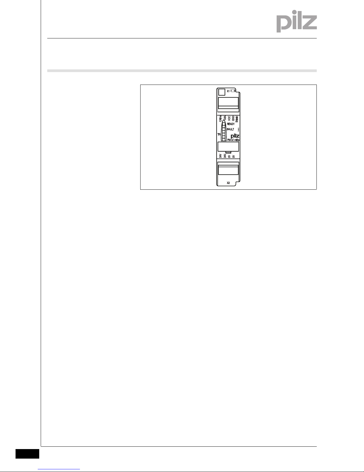
2.2Front view2200Front view2-Klemmenbelegung
Legende
Key:
` 0 V, 24 V:
Supply connections
` CAN+, CAN-, VCC, GND:
Connection for decentralised modules
` Shield:
Connection for the cable shield
Page 11

Pilz GmbH & Co. KG, Felix-Wankel-Straße 2, 73760 Ostfildern, Germany
Telephone: +49 711 3409-0, Telefax: +49 711 3409-133, E-Mail: pilz.gmbh@pilz.de
3-1
3.1 Intended use
3 Safety
33000SafetySafety3-3.1Intended use3100Intended use3-Bestimmung/Gertebeschreibung_multi_Verbindunsmod_ml2p
The expansion module is used to connect decentralised input/output
modules to a safety system PNOZmulti.
Bestimmung/Gertebeschreibung_multi_Zusatz_Modul
The expansion module may only be connected to a base unit from the
PNOZmulti modular safety system.
Bestimmung/Gertebeschreibung_multi_System
The PNOZmulti modular safety system is used for the safety-related interruption of safety circuits and is designed for use on:
` E-STOP equipment
` Safety circuits in accordance with VDE 0113 Part 1 and EN 60204-1
Bestimmung/Gertebeschreibung_Ausschluss
Intended use includes making the electrical installation EMC-compliant.
The product is designed for use in an industrial environment. It is not
suitable for use in a domestic environment, as this can lead to interference.
The following is deemed improper use in particular:
` Any component, technical or electrical modification to the product
` Use of the product outside the areas described in this manual
` Use of the product outside the technical details (see chapter entitled
“Technical Details”)
Page 12

3.2 System requirements
3 Safety
Pilz GmbH & Co. KG, Felix-Wankel-Straße 2, 73760 Ostfildern, Germany
Telephone: +49 711 3409-0, Telefax: +49 711 3409-133, E-Mail: pilz.gmbh@pilz.de
3-2
3.2System requirements3200System requirements3-Systemvoraussetzungen PNOZ ml2p
` PNOZmulti Configurator: from Version 7.0.0
` Base unit PNOZ m0p: from Version 3.0
` Base unit PNOZ m1p: from Version 6.0
` Base unit PNOZ m1p ETH: from Version 2.0
` Base unit PNOZ m2p: from Version 3.0
` Base unit PNOZ m3p: from Version 2.0
Please contact Pilz if you have an older version.
Page 13

Pilz GmbH & Co. KG, Felix-Wankel-Straße 2, 73760 Ostfildern, Germany
Telephone: +49 711 3409-0, Telefax: +49 711 3409-133, E-Mail: pilz.gmbh@pilz.de
3-3
3.3 Safety regulations
3 Safety
3.3Safety regulations3300Safety regulations3-
3.3.1 Use of qualified personnel
Use of qualified personnel3-Sich Qualif. Personal
The products may only be assembled, installed, programmed, commissioned, operated, maintained and decomissioned by persons with proven skills. Persons with proven skills are people who, because they are:
` Qualified electrical engineers or
` Have received training from qualified electrical engineers
are suitably experienced to operate devices, systems, plant and machinery in accordance with the general standards and guidelines for
safety technology.
It is the company's responsibility only to employ personnel who:
` Are familiar with the basic regulations concerning health and safety /
accident prevention
` Have read and understood the safety guidelines given in this descrip-
tion
` Have a good knowledge of the generic and specialist standards ap-
plicable to the specific application.
3.3.2 Warranty and liability
Warranty and liability3-Sich Gewhrleistung
All claims to warranty and liability will be rendered invalid if:
` The product was used contrary to the purpose for which it is intended
` Damage can be attributed to not having followed the guidelines in the
manual
` Operating personnel are not suitably qualified
` Any type of modification has been made (e.g. exchanging compo-
nents on the PCB boards, soldering work etc.).
3.3.3 Disposal
Disposal3-Sich Ent sorgung_alt
The product must be disposed of properly when it reaches the end of its
service life.
Page 14

3.3 Safety regulations
3 Safety
Pilz GmbH & Co. KG, Felix-Wankel-Straße 2, 73760 Ostfildern, Germany
Telephone: +49 711 3409-0, Telefax: +49 711 3409-133, E-Mail: pilz.gmbh@pilz.de
3-4
3.3.4 For your safety
For your safety3-Zu Ihrer Sicherheit_multi_Module
The unit meets all necessary conditions for safe operation. However,
you should always ensure that the following safety requirements are
met:
` This operating manual only describes the basic functions of the unit.
Information on the advanced functions can be found in the online help
for the PNOZmulti Configurator and in the PNOZmulti technical catalogue. Only use these functions after you have read and understood
the documentation. All necessary documentation can be found on the
PNOZmulti Configurator CD.
` Do not open the housing or make any unauthorised modifications.
` Please make sure you shut down the supply voltage when performing
maintenance work (e.g. exchanging contactors).
Page 15

Pilz GmbH & Co. KG, Felix-Wankel-Straße 2, 73760 Ostfildern, Germany
Telephone: +49 711 3409-0, Telefax: +49 711 3409-133, E-Mail: pilz.gmbh@pilz.de
4-1
4.1 Device properties
4 Function description
44000Function descriptionFunction description4-4.1Device properties4100Device properties4-
4.1.1 Integrated protection mechanisms
Integrated protection mechanisms4-Sicherheitseigenschaften_multi_allgemein
The relay conforms to the following safety criteria:
` The circuit is redundant with built-in self-monitoring.
` The safety function remains effective in the case of a component fail-
ure.
4.1.2 Function description
Function description4-
4.1.2.1 Operation
Operation4-Funktionsbeschreibung PNOZ ml2p
The link module PNOZ ml2p is used to safely transfer the input information from decentralised modules to the safety system PNOZmulti.
Funktionen_multi_Basis
The function of the safety system's inputs and outputs depends on the
safety circuit created using the PNOZmulti Configurator. A chip card is
used to download the safety circuit to the base unit. The base unit has
2 microcontrollers that monitor each other. They evaluate the input circuits on the base unit and expansion modules and switch the outputs on
the base unit and expansion modules accordingly.
The LEDs on the base unit and expansion modules indicate the status
of the PNOZmulti safety system.
The online help on the PNOZmulti Configurator contains descriptions of
the operating modes and all the functions of the PNOZmulti safety system, plus connection examples.
Funktionsbeschreibung PNOZ ml2p_2
Data exchange:
` Communication with the decentralised modules is via a safe data link.
` The link module PNOZ ml2p reads the input information from the de-
centralised modules as part of each cycle and then forwards it to the
base unit.
` At the end of a PNOZmulti cycle, the base unit sends its output data
to its link module. This output data is immediately sent to the decentralised modules.
Page 16
4.1 Device properties
4 Function description
Pilz GmbH & Co. KG, Felix-Wankel-Straße 2, 73760 Ostfildern, Germany
Telephone: +49 711 3409-0, Telefax: +49 711 3409-133, E-Mail: pilz.gmbh@pilz.de
4-2
Linking several decentralised modules:
` A maximum of 4 link modules can be connected to a PNOZmulti base
unit.
` A maximum of 4 decentralised modules can be connected to a link
module PNOZ ml2p.
` If a decentralised module receives data intended for a different de-
centralised module that is connected, the data is forwarded without
being processed.
4.1.2.2 Block diagram
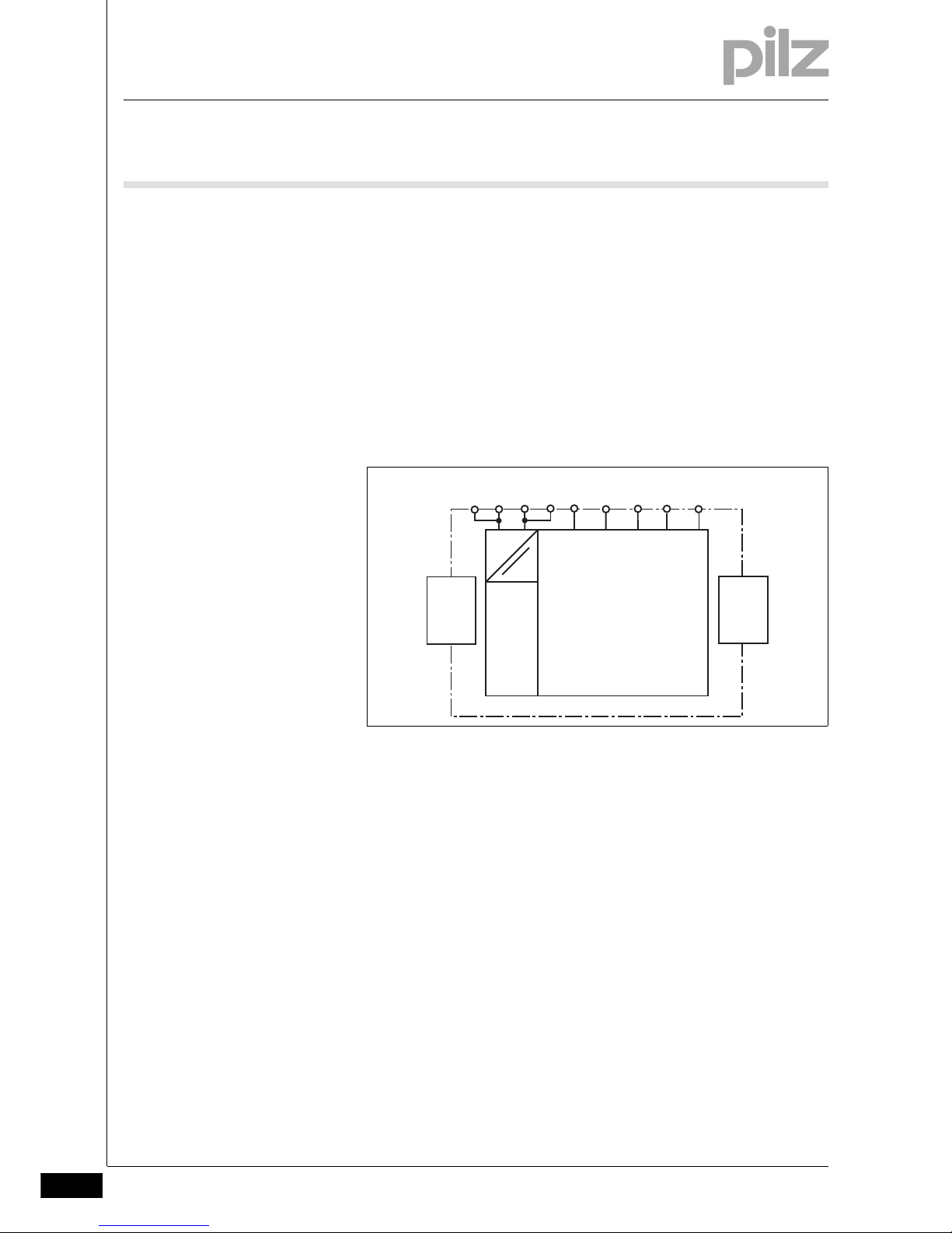
Block diagram4-Blockschaltbild PNOZ ml2p
Fig. 4-1: Block diagram
24V 24V
=
Power
=
0V 0V
Interface
to previous
module
Interface
to next
module
CAN+ CAN-
VCC GND
Shield
Page 17
Pilz GmbH & Co. KG, Felix-Wankel-Straße 2, 73760 Ostfildern, Germany
Telephone: +49 711 3409-0, Telefax: +49 711 3409-133, E-Mail: pilz.gmbh@pilz.de
5-1
5.1 General installation guidelines
5 Installation
55000InstallationInstallation5-5.1General installation guidelines5100General installation guidelines5-Montage_multi_allgemein
` The safety system should be installed in a control cabinet with a pro-
tection type of at least IP54. Fit the safety system to a horizontal DIN
rail. The venting slots must face upward and downward. Other mounting positions could destroy the safety system.
` Use the notches on the back of the unit to attach it to a DIN rail. Con-
nect the safety system to the DIN rail in an upright position so that the
earthing springs on the safety system are pressed on to the DIN rail.
` The ambient temperature of the PNOZmulti units in the control cabi-
net must not exceed the figure stated in the technical details, otherwise air conditioning will be required.
` To comply with EMC requirements, the DIN rail must have a low im-
pedance connection to the control cabinet housing.
Montage_EMV ESD
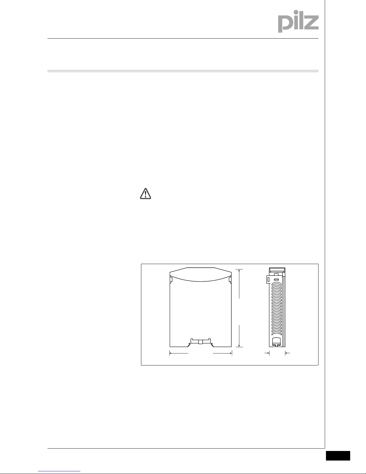
5.1.1 Dimensions
Dimensions5-Abmessungen
CAUTION!
Damage due to electrostatic discharge!
Electrostatic discharge can damage components. Ensure
against discharge before touching the product, e.g. by touching
an earthed, conductive surface or by wearing an earthed armband.
94 (3.70")
22,5
(0.88")
121 (4.76")
Page 18
5.2 Connecting the base unit and expansion modules
5 Installation
Pilz GmbH & Co. KG, Felix-Wankel-Straße 2, 73760 Ostfildern, Germany
Telephone: +49 711 3409-0, Telefax: +49 711 3409-133, E-Mail: pilz.gmbh@pilz.de
5-2
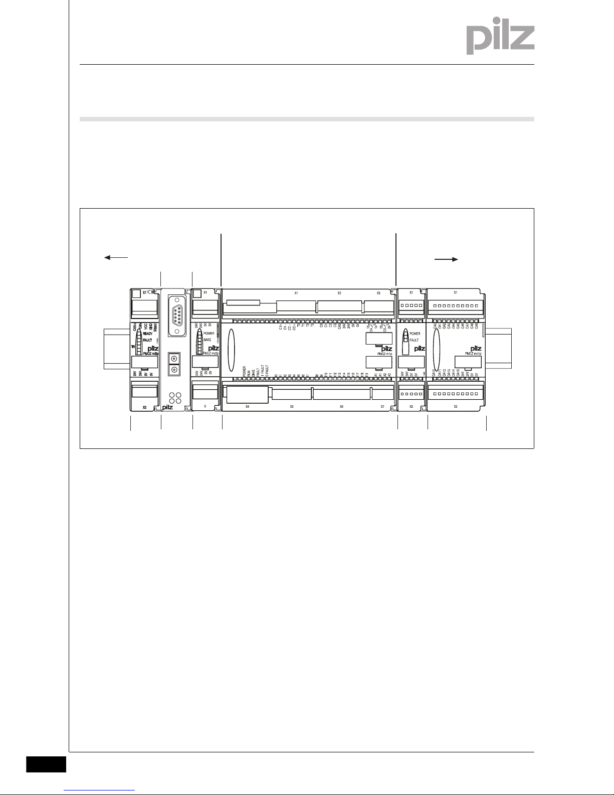
5.2Connecting the base unit and expansion modules5200Connecting the base unit and expansion modules5-Montage_multi_Modul_verbind_links_BA
` Do not connect terminators to the last expansion module.
` Install the expansion module in the position in which it is configured
in the PNOZmulti Configurator.
Montage_multi_Anzahl_Module_links_4
You can install a maximum of 4 PNOZ ml2p to the left of the base unit.
Montage
Fig. 5-2: Connecting the base unit and expansion modules
CHIP-Card
PNOZ mo3p
O1+
O0-
O0+
O1-
PROFIBUS-DP
PNOZ mc3p
FAULT
OFFLINE
x1
x10
X1
ONLINE
ADDRESS
773700
Base unit
Fieldbus module
Max. 8 expansion
modules
8
Position
1
2
...
2
Power supply
Max. 4 expansion
modules
0-5 -1-2...
Page 19

Pilz GmbH & Co. KG, Felix-Wankel-Straße 2, 73760 Ostfildern, Germany
Telephone: +49 711 3409-0, Telefax: +49 711 3409-133, E-Mail: pilz.gmbh@pilz.de
6-1
6.1 General wiring guidelines
6 Commissioning
61000CommissioningCommissioning6-6.1General wiring guidelines1100General wiring guidelines6-Verdrahtung_multi_Modu l
The wiring is defined in the circuit diagram of the PNOZmulti Configurator.
Note:
` Information given in the "Technical details" must be followed.
Verdrahtung PNOZ ml2p
` 2 connection terminals are available for each of the supply connec-
tions 24 V and 0 V. This means that the supply voltage can be looped
through several connections. The current at each terminal may not
exceed 3 A.
` Please refer to the technical details for information on the maximum
cable length. Please also read the section entitled "Voltage drop".
` Shielded cable must be used from a cable length of 30 m.
` Pilz pre-assembled cable can be used to connect the decentralised
modules (see order reference).
` The plug-in connection terminals are either designed as cage clamp
terminals or screw terminals (see order reference).
Verdrahtung_multi_Modul_Achtung_Kabel_spannungsl_ziehen
6.1.1 Insulation voltage test
Insulation voltage test6-Isolationsspannungsprüfung
The product PNOZ ml2p is connected to functional earth via protection elements on the supply voltage. Insulation voltage tests are only
possible with voltages up to ca. 42 V.
CAUTION!
Only connect and disconnect the expansion module when the
supply voltage is switched off.
Page 20

6.2 Preparing for operation
6 Commissioning
Pilz GmbH & Co. KG, Felix-Wankel-Straße 2, 73760 Ostfildern, Germany
Telephone: +49 711 3409-0, Telefax: +49 711 3409-133, E-Mail: pilz.gmbh@pilz.de
6-2
6.2Preparing for operation6200Preparing for operation6-
6.2.1 Download modified project to the PNOZmulti safety system
Download modified project to the PNOZmulti safety system6-Verdrahtung_multi_Modul_Betr_geaend_Projekt_BA
As soon as an additional expansion module has been connected to the
system, the project must be amended using the PNOZmulti Configurator. Proceed as described in the operating instructions for the base unit.
6.2.2 Connection
Connection6-Betriebsbereitschaft herstellen Anschluss_PNOZ ml2p
` Supply voltage
` Connection to a decentralised input module PDP67
Betriebsbereitschaft hers tellen Anschluss - LC-Kabel_PNOZ m l2p
` Connection when using the PSS SB BUSCABLE LC in conjunction with a Pilz self-assembly "PSS67 M12
connector" (see order reference in the Technical Catalogue)
NOTICE
For the commissioning and after every program change, you
must check whether the safety devices are functioning correctly.
Supply voltage AC DC
24V
+ 24 V DC
0 V
24V
0V
0V
CAN+
CAN-
VCC
GND
Shield
VCC
CANGND
CAN+
Shield
PNOZ ml2p
PDP67 F 8DI ION
1
2
3
4
5
CAN+
CAN-
VCC
GND
Shield
PNOZ ml2p
PDP67 F 8DI ION
1
2
3
4
5
red
brown
white
green
VCC
CANGND
CAN+
Shield
Page 21
Pilz GmbH & Co. KG, Felix-Wankel-Straße 2, 73760 Ostfildern, Germany
Telephone: +49 711 3409-0, Telefax: +49 711 3409-133, E-Mail: pilz.gmbh@pilz.de
6-3
6.3 Series connection of 4 decentralised modules
6 Commissioning
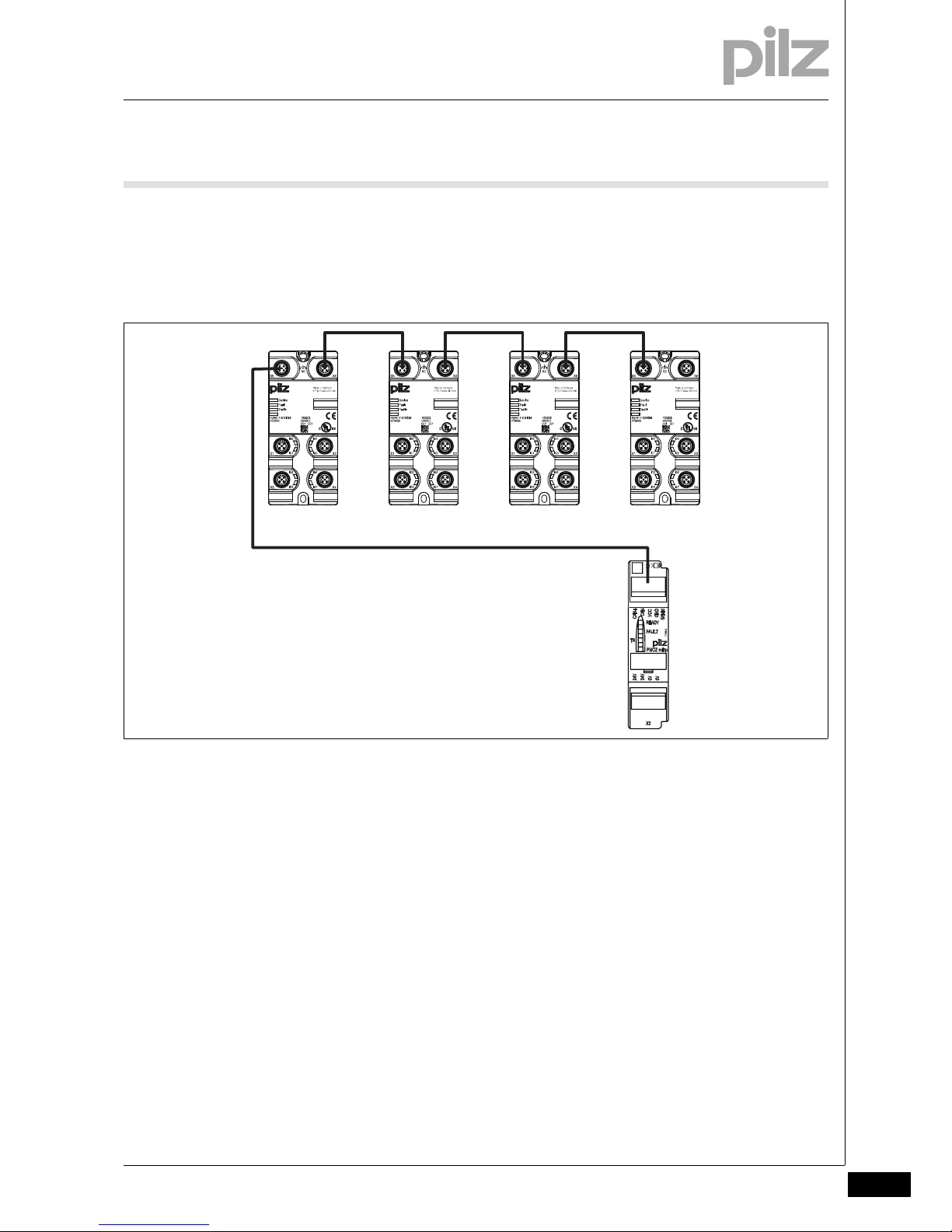
6.3Series connection of 4 decentralised modules6300Series connection of 4 decentralised modules6-Anschluss_PDP_DI_4_Module
You can connect up to 4 decentralised modules in series to a PNOZmulti
link module.
PNOZ ml2p
Page 22

6.4 Voltage drop
6 Commissioning
Pilz GmbH & Co. KG, Felix-Wankel-Straße 2, 73760 Ostfildern, Germany
Telephone: +49 711 3409-0, Telefax: +49 711 3409-133, E-Mail: pilz.gmbh@pilz.de
6-4
6.4Voltage drop6400Voltage drop6-Verdrahtung_PNOZ ml2p_Leitungslänge-Spannungsabfall
The max. cable length depends on the voltage drop in the supply voltage
cables. The level of voltage drop is determined by the:
` Cable resistance on the supply voltage cables
` Operating current of the modules
` Load on the modules
To increase the max. cable length, the input voltage can be permanently
increased by the voltage tolerance (see Technical Details).
6.4.1 Guidelines for various cable types
Guidelines for various cable types6-Verdrahtung_PNOZ ml2p_Leitungslänge-Spannungsabfall-Richtwerte
Guidelines for calculating the voltage drop on various cable types
Cable type Voltage drop per 10 m and per 100
mA
PSS SB BUSCABLE LC 0.1 V
Sensor cable 0.25 mm
2
0.15 V
Sensor cable 0.34 mm
2
0.11 V
Sensor cable 0.5 mm
2
0.07 V
Page 23

Pilz GmbH & Co. KG, Felix-Wankel-Straße 2, 73760 Ostfildern, Germany
Telephone: +49 711 3409-0, Telefax: +49 711 3409-133, E-Mail: pilz.gmbh@pilz.de
6-5
6.4 Voltage drop
6 Commissioning
6.4.2 Calculation example
Calculation example6-Verdrahtung_PNOZ_ml2p_Leitungslänge-Spannungsabfall-Beispiel
` The PSS SB BUSCABLE LC is used in accordance with the pin as-
signment in section 6.2.2.
Voltage drop per 10 m and per 100 mA: 0.1 V
Key:
` I0: Module's consumption.
` I1 ... I5: Load current taken from the module
` U1 … U4: Voltage drop on the respective connection path
Total voltage drop from the link module PNOZ ml2p to the final PDP67
F 8DI ION:
U
total
= U1 + U2 + U3 + U
4
U
total
= 1.3 V + 0.825 V + 0.5 V + 0.10 V = 2.725 V
PNOZmulti Base Unit
4*I0+I1+I2+I3+I4
650 mA
U = 1,3 V
I0+I4
100 mA
U = 0,10 V
2*I0+I3+I4
250 mA
U = 0,5 V
3*I0+I2+I3+I4
550 mA
U = 0,55 V
20 m
20 m
15 m
10 m
I0=50 mA
I4 = 50 mA
I3 =100 mA
I2 = 250 mA I1 = 50 mA
Link
Module
PNOZ
ml2p
PDP67 F 8DI ION
I0=50 mA
PDP67 F 8DI ION
I0=50 mA
PDP67 F 8DI ION
I0=50 mA
PDP67 F 8DI ION
Page 24

6 Commissioning
Pilz GmbH & Co. KG, Felix-Wankel-Straße 2, 73760 Ostfildern, Germany
Telephone: +49 711 3409-0, Telefax: +49 711 3409-133, E-Mail: pilz.gmbh@pilz.de
6-6
Page 25

Pilz GmbH & Co. KG, Felix-Wankel-Straße 2, 73760 Ostfildern, Germany
Telephone: +49 711 3409-0, Telefax: +49 711 3409-133, E-Mail: pilz.gmbh@pilz.de
7-1
7.1 Messages
7 Operation
77000OperationOperation7-7.1Messages71 00Messages7-Betrieb_Meldungen_allgemein_BA
When the supply voltage is switched on, the PNOZmulti safety system
copies the configuration from the chip card.
The LEDs "POWER","DIAG", "FAULT", "IFAULT" and "OFAULT" light up
on the base unit.
Betrieb_Meldungen_Modul_R eady_BA
The PNOZmulti safety system is ready for operation when the "POWER"
and "RUN" LEDs on the base unit and the "READY" LED on the
PNOZ ml2p are lit continuously.
Page 26

7.2 Display elements
7 Operation
Pilz GmbH & Co. KG, Felix-Wankel-Straße 2, 73760 Ostfildern, Germany
Telephone: +49 711 3409-0, Telefax: +49 711 3409-133, E-Mail: pilz.gmbh@pilz.de
7-2
7.2Display elements7200Display elements7-Anzeige Legende 3x
Key:
7.2.1 Display elements for device diagnostics
Display elements for device diagnostics7-Betrieb_Anzeig e_Verbindungsmodul ml2p_BA
LED on
LED flashes
LED off
LED LED status Meaning
READY Green The unit is ready for operation
The unit is not ready for operation
FAULT Red External error
Red Internal error
No error
TR Yel-
low
Connection to a decentralised module available
Yellow
Connection is not available to all decentralised modules.
No connection to a decentralised module
Page 27

Pilz GmbH & Co. KG, Felix-Wankel-Straße 2, 73760 Ostfildern, Germany
Telephone: +49 711 3409-0, Telefax: +49 711 3409-133, E-Mail: pilz.gmbh@pilz.de
7-3
7.3 Fault detection
7 Operation
7.3Fault detection7300Fault detection7-Fehlererkenn ung PNOZ ml2p
The base unit contains information about the
` Link module (in order, defective, no supply voltage)
` Status of communication with the decentralised modules (data valid,
data invalid)
If the connection to a decentralised module is interrupted or there is a
major error on the decentralised module, the inputs on the devices connected to the link module are set to zero. The base unit remains in a RUN
condition.
Page 28

7 Operation
Pilz GmbH & Co. KG, Felix-Wankel-Straße 2, 73760 Ostfildern, Germany
Telephone: +49 711 3409-0, Telefax: +49 711 3409-133, E-Mail: pilz.gmbh@pilz.de
7-4
Page 29
Pilz GmbH & Co. KG, Felix-Wankel-Straße 2, 73760 Ostfildern, Germany
Telephone: +49 711 3409-0, Telefax: +49 711 3409-133, E-Mail: pilz.gmbh@pilz.de
8-1
8.1 Technical Details
8 Technical Details
88000Technical DetailsTechnical Details8-8.1Technical Details8100Technical Details8-][Technische Daten_multi_PNOZ_ml2p
Technical details
Electrical data
Supply voltage UB DC 24 V
Voltage tolerance -15 %/+20 %
Power consumption at U
B
DC
without load 5.0 W
Residual ripple DC 5 %
Status display LED
Times
Switch-on delay 5.00 s
Supply interruption before de-energisation 20 ms
Maximum input delay 15 ms
Switch-off delay 35 ms
Outputs
Maximum output current decentralised module supply 4 A
Short-circuit protection of the decentralised module supply
yes
Environmental data
EMC EN 60947-5-1
Vibration to EN 60068-2-6
Frequency 10 - 55 Hz
Amplitude 0.35 mm
Climatic suitability EN 60068-2-78
Airgap creepage in accordance with EN 60664-1
Ambient temperature 0 - 60 °C
Storage temperature -25 - 70 °C
Mechanical data
Protection type
Mounting (e.g. cabinet) IP54
Housing IP20
Terminals IP20
DIN rail
Top hat rail 35 x 7.5 EN 50022
Recess width 27 mm
Maximum cable run unscreened 30 m
Maximum cable run screened 100 m
Housing material
Housing PPO UL 94 V0
Front ABS UL 94 V0
Cross section of external conductors with screw terminals
1 core flexible 0.50 - 1.50 mm² , 22 - 14 AWG
2 core, same cross section, flexible:
with crimp connectors, without insulating sleeve 0.50 - 0.75 mm² , 22 - 20 AWG
without crimp connectors or with TWIN crimp connectors 0.50 - 0.75 mm² , 22 - 20 AWG
2 core, same cross section, flexible:
Torque setting with screw terminals 0.25 Nm
Cross section of external conductors with spring-loaded
terminals: Flexible with/without crimp connectors
0.50 - 1.50 mm² , 26 - 14 AWG
Spring-loaded terminals: Terminal points per connection 1
Stripping length 9 mm
Page 30

8.1 Technical Details
8 Technical Details
Pilz GmbH & Co. KG, Felix-Wankel-Straße 2, 73760 Ostfildern, Germany
Telephone: +49 711 3409-0, Telefax: +49 711 3409-133, E-Mail: pilz.gmbh@pilz.de
8-2
Si-Kennzahlen_alle
Si_Kennzahlen_Erläuterung
All the units used within a safety function must be considered when calculating the safety characteristic data.
Technische Daten_Satz No rmen
The standards current on 2009-12 apply.
Dimensions
Height 94.0 mm
Width 22.5 mm
Depth 121.0 mm
Weight 120 g
Safety characteristic data
Unit Operating mode
EN ISO 13849-1PLEN 954-1
Category
EN IEC 62061
SIL CL PFH [1/h] tM [year]
PL e (Cat. 4) Cat. 4 SIL CL 3 5.35E-09 20
Mechanical data
Page 31

Pilz GmbH & Co. KG, Felix-Wankel-Straße 2, 73760 Ostfildern, Germany
Telephone: +49 711 3409-0, Telefax: +49 711 3409-133, E-Mail: pilz.gmbh@pilz.de
8-3
8.2 Order reference
8 Technical Details
8.2Order reference1200Order reference8-Best elldaten PN OZ ml2p
Order reference
Type Features Order no.
PNOZ ml2p Link module 773 602
Set spring term 1 set of cage clamp terminals 783 400
Set spring term 1 set of screw terminals 793 400
PSS SB BUSCABLE LC Cable, shielded 1 - 100 m 311 074
PSS67 I/O Cable Cable 1 - 30 m 380 320
PSS67 Cable M8sf M12sm Cable, straight M12 connector, straight M8 socket, 5-pin 3 m 380 200
PSS67 Cable M8sf M12sm Cable, straight M12 connector, straight M8 socket, 5-pin 5 m 380 201
PSS67 Cable M8sf M12sm Cable, straight M12 connector, straight M8 socket, 5-pin 10 m 380 202
PSS67 Cable M8sf M12sm Cable, straight M12 connector, straight M8 socket, 5-pin 30 m 380 203
PSS67 Cable M8sf M12sm Cable, straight M12 connector, angled M8 socket, 5-pin 3 m 380 204
PSS67 Cable M8sf M12sm Cable, straight M12 connector, angled M8 socket, 5-pin 5 m 380 205
PSS67 Cable M8sf M12sm Cable, straight M12 connector, angled M8 socket, 5-pin 10 m 380 206
PSS67 Cable M8sf M12sm Cable, straight M12 connector, angled M8 socket, 5-pin 30 m 380 207
PSS67 Cable M12sf M12sm Cable, straight M12 connector, straight M12 socket, 5-pin 3 m 380 208
PSS67 Cable M12sf M12sm Cable, straight M12 connector, straight M12 socket, 5-pin 5 m 380 209
PSS67 Cable M12sf M12sm Cable, straight M12 connector, straight M12 socket, 5-pin 10 m 380 210
PSS67 Cable M12sf M12sm Cable, straight M12 connector, straight M12 socket, 5-pin 30 m 380 211
PSS67 Cable M12sf M12sm Cable, angled M12 connector, angled M12 socket, 5-pin 3 m 380 212
PSS67 Cable M12sf M12sm Cable, angled M12 connector, angled M12 socket, 5-pin 5 m 380 213
PSS67 Cable M12sf M12sm Cable, angled M12 connector, angled M12 socket, 5-pin 10 m 380 214
PSS67 Cable M12sf M12sm Cable, angled M12 connector, angled M12 socket, 5-pin 30 m 380 215
PSEN ma adapter Adapter for connection to safety switch PSENmag 380 300
PSEN cs adapter Adapter for connection to safety switch PSENcode 380 301
PSS67 M12 connector Connector, M12, straight, 5-pin, A-coded 380 308
PSS67 M12 connector Socket, M12, straight, 5-pin, A-coded 380 309
PSS67 M12 connector Connector, M12, angled, 5-pin, A-coded 380 310
PSS67 M12 connector Socket, M12, angled, 5-pin, A-coded 380 311
PSS67 M8 connector Connector, M8, straight, 4-pin 380 316
PSS67 M8 connector Socket, M8, straight, 4-pin 380 317
PSS67 M8 connector Connector, M8, angled, 4-pin 380 318
PSS67 M8 connector Socket, M8, angled, 4-pin 380 319
Page 32

8 Technical Details
Pilz GmbH & Co. KG, Felix-Wankel-Straße 2, 73760 Ostfildern, Germany
Telephone: +49 711 3409-0, Telefax: +49 711 3409-133, E-Mail: pilz.gmbh@pilz.de
8-4
Page 33
1001642-EN-03, 2010-09 Printed in Germany
© Pilz GmbH & Co. KG, 2009
Pilz GmbH & Co. KG
Felix-Wankel-Straße 2
73760 Ostfildern, Germany
Telephone: +49 711 3409-0
Telefax: +49 711 3409-133
E-Mail: pilz.gmbh@pilz.de
www.pilz.com
+49 711 3409-444
support@pilz.com
Technical support
In many countries we are
represented by our subsidiaries
and sales partners.
Please refer to our homepage
for further details or contact our
headquarters.
... www
 Loading...