

Products
Expansion modules
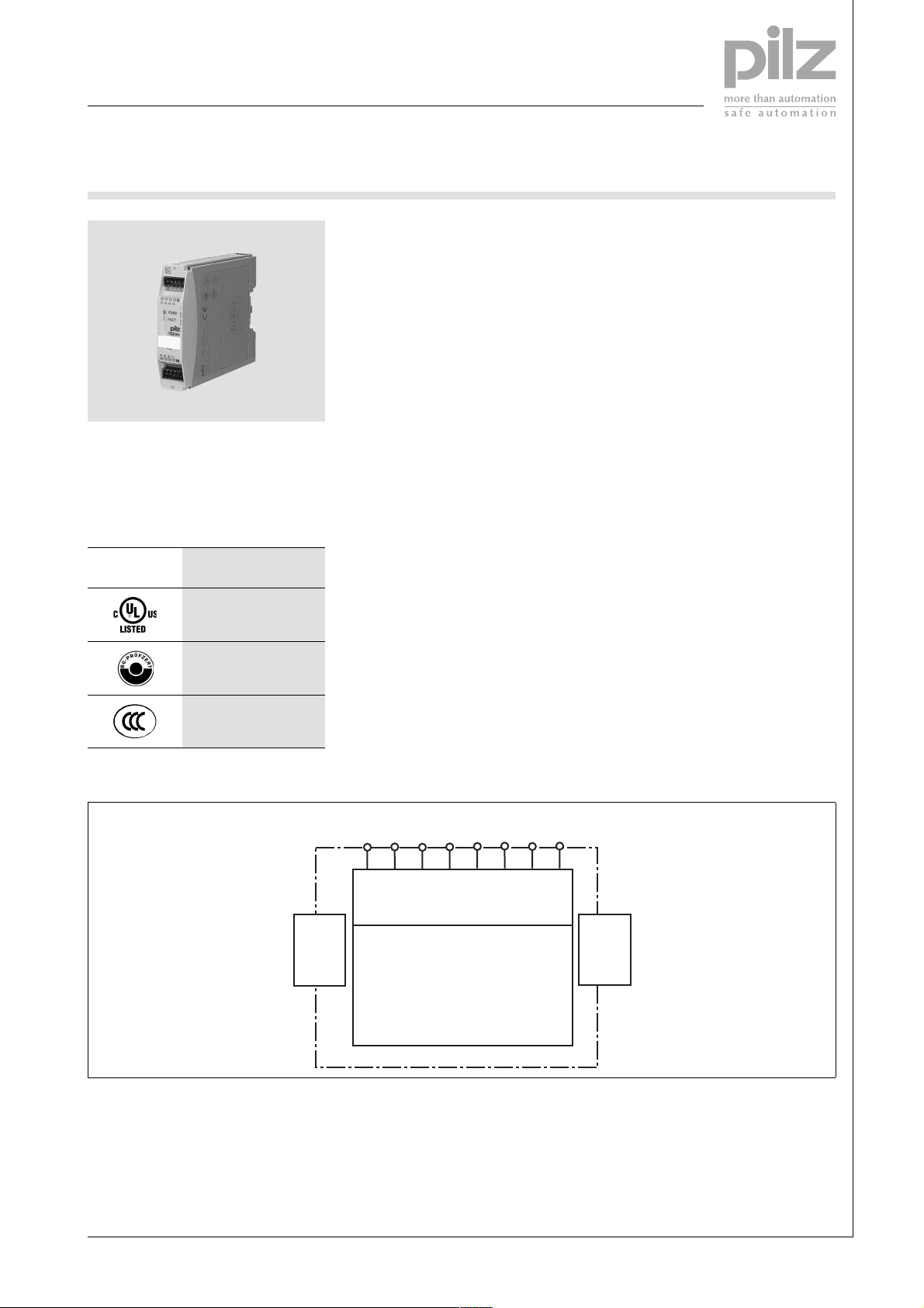
PNOZ mi1p
Expansion module for connection to a
base unit from the PNOZmulti modular
safety system
Approvals
PNOZ mi1p
Unit features
` 8 inputs for connecting:
– E-STOP pushbutton
– Two-hand button
– Safety gate limit switch
– Reset button
– Light barrier
– Scanner
– Enable switch
– PSEN
– Operating mode selector switch
` Can be configured in the
PNOZmulti Configurator
` LED indicator for:
– Status of the PNOZmulti safety
system
` Max. 8 PNOZ mi1p units can be
connected to the base unit
` Test pulse outputs used to detect
shorts across the inputs
` Plug-in connection terminals (either
cage clamp terminal or screw terminal)
Unit description
The expansion module may only be
connected to a base unit from the
PNOZmulti modular safety system.
The PNOZmulti modular safety system
is used for the safety-related interruption of safety circuits and is designed
for use in:
` Emergency stop equipment
` Safety circuits in accordance with
VDE 0113 Part 1 and EN 60204-1
Safety features
The relay conforms to the following
safety criteria:
` The circuit is redundant with built-in
self-monitoring.
` The safety function remains effec-
tive in the case of a component failure.
Block diagram
module
Interface
to previous
I0 I1
I2 I3 I4 I5 I6 I7
Input
to next
module
Interface
Pilz GmbH & Co. KG, Sichere Automation, Felix-Wankel-Straße 2, 73760 Ostfildern, Germany
Telephone: +49 711 3409-0, Telefax: +49 711 3409-133, E-Mail: pilz.gmbh@pilz.de
NSG-D-2-369-2006-02

Products
Expansion modules
PNOZ mi1p
Function description
The expansion module provides additional inputs.
The function of the inputs on the safety
system depends on the safety circuit
created using the PNOZmulti Configu-
Wiring
The wiring is defined in the circuit diagram of the PNOZmulti Configurator.
Please note:
` Information given in the "Technical
details" must be followed.
` Connection terminals I0 ... I7 are in-
puts
` Power for the safety system and in-
put circuits must always be provided from a single power supply. The
power supply must meet the regulations for extra low voltages with
safe separation.
` The test pulse outputs on the base
unit must be used to detect shorts
across contacts.
` Use copper wire that can withstand
75 °C.
rator. A chip card is used to download
the safety circuit to the base unit. The
base unit has 2 microcontrollers that
monitor each other. They evaluate the
input circuits on the base unit and expansion modules and switch the out-
puts on the base unit and expansion
modules accordingly.
The online help on the PNOZmulti
Configurator contains descriptions of
the operating modes and all the functions of the PNOZmulti safety system,
plus connection examples.
Telephone: +49 711 3409-0, Telefax: +49 711 3409-133, E-Mail: pilz.gmbh@pilz.de
NSG-D-2-369-2006-02Pilz GmbH & Co. KG, Sichere Automation, Felix-Wankel-Straße 2, 73760 Ostfildern, Germany
-2

Products
Expansion modules
PNOZ mi1p
Preparing for operation
` Input circuit
Input circuit Single-channel Dual-channel
Example:
E-STOP
without detection of shorts across contacts
S1
I0
L+
S1
I0
I1
L+
L+
Example:
E-STOP
with detection of shorts across contacts
` Key
S1 E-STOP pushbutton
T0
I0
S1
T1
T0
S1
I0
I1
Pilz GmbH & Co. KG, Sichere Automation, Felix-Wankel-Straße 2, 73760 Ostfildern, Germany
Telephone: +49 711 3409-0, Telefax: +49 711 3409-133, E-Mail: pilz.gmbh@pilz.de
NSG-D-2-369-2006-02

Products
Expansion modules
PNOZ mi1p
Terminal configuration
773400
Installation
` The safety system should be in-
stalled in a control cabinet with a
protection type of at least IP54. Fit
the safety system to a horizontal
DIN rail. The venting slots must face
upward and downward. Other
mounting positions could damage
the safety system.
` Use the notches on the back of the
unit to attach it to a DIN rail. Connect the safety system to the DIN
rail in an upright position, so that
the earthing springs on the safety
system are pressed on to the DIN
rail.
` To comply with EMC requirements,
the DIN rail must have a low impedance connection to the control cabinet housing.
Dimensions
94 (3.70")
121 (4.76")
22,5
(0.88")
Telephone: +49 711 3409-0, Telefax: +49 711 3409-133, E-Mail: pilz.gmbh@pilz.de
NSG-D-2-369-2006-02Pilz GmbH & Co. KG, Sichere Automation, Felix-Wankel-Straße 2, 73760 Ostfildern, Germany
-4

Products
Expansion modules
PNOZ mi1p
Notice This data sheet is only intended for use
during configuration. For installation
erating instructions supplied with the
unit.
and operation, please refer to the op-
Technical details
Electrical data
Supply voltage (UB) 24 VDC
Power consumption at U
Times
Switch-on delay 5 s (after UB is applied)
Simultaneity channel 1/2/3 3 s, two-hand control relay: 0.5 s
Supply interruption before de-energisation Min. 20 ms
Inputs
Number 8
Voltage and current 24 VDC/8 mA
Galvanic isolation No
Signal level at “0” -3 ... +5 VDC
Signal level at “1” 15 ... 30 VDC
Input delay 0.6 ... 4 ms
Status indicator LED
Environmental data
Airgap creepage DIN VDE 0110-1, 04/97
Vibration in accordance with EN 60068-2-6, 04/95
Frequency:
Amplitude:
Climatic suitability EN 60068-2-78, 10/01
EMC EN 60947-5-1, 11/97
Ambient temperature 0 ... + 55 °C
Storage temperature -25 ... + 70 °C
Mechanical data
Protection type
Mounting (e.g. cabinet)
Housing
Terminals
DIN rail
Top hat rail
Inner width
Cable cross section
Rigid single-core, flexible multi-core or multi-core
with crimp connector 0.5 ... 1.5 mm2
without load Max. 8.0 W + 2.5 W per expansion module
B
10 ... 55 Hz
0.35 mm
IP54
IP20
IP20
35 x 7.5 EN 50022
27 mm
Torque setting for connection terminals (screws) 0.2 ... 0.25 Nm
Housing material
Housing
Front
Dimensions (H x W x D) 94 x 22.5 x 121 mm
Weight with connector 130 g
Order reference
Type Features Order no.
PNOZ mi1p Expansion module 8 inputs 773 400
Pilz GmbH & Co. KG, Sichere Automation, Felix-Wankel-Straße 2, 73760 Ostfildern, Germany
Telephone: +49 711 3409-0, Telefax: +49 711 3409-133, E-Mail: pilz.gmbh@pilz.de
PPO UL 94 V0
ABS UL 94 V0
NSG-D-2-369-2006-02
 Loading...