

Page 1
21 255-01
PNOZ mc9p
4
D Betriebsanleitung
4
GB Operating instructions
4
F Manuel d'utilisation
Erweiterungsmodul PNOZ mc9p
PROFINET IO
Das Erweiterungsmodul PNOZ mc9p darf nur
an ein Basisgerät (z. B. PNOZ m1p des
modularen Sicherheitssystems PNOZmulti)
angeschlossen werden. Es koppelt das
modulare Sicherheitssystem PNOZmulti an
Steuerungen an, die das Protokoll
PROFINET IO unterstützen. Das modulare
Sicherheitssystem PNOZmulti dient dem
sicherheitsgerichteten Unterbrechen von
Sicherheitsstromkreisen und ist bestimmt für
den Einsatz in:
• NOT-AUS-Einrichtungen
• Sicherheitsstromkreisen nach VDE 0113
Teil 1, 11/98 und EN 60204-1, 12/97
(z. B. bei beweglichen Verdeckungen)
Achtung! Das Erweiterungsmodul
PNOZ mc9p darf nicht für
sicherheitsgerichtete Funktionen
verwendet werden.
Lieferumfang:
• Erweiterungsmodul PNOZ mc9p
• Steckbrücke (siehe Abschnitt Ersatzteile)
4 E Instrucciones de uso
4 I Istruzioni per l`uso
4 NL Gebruiksaanwijzing
PNOZ mc9p expansion module
PROFINET IO
The PNOZ mc9p expansion module may
only be connected to a base unit (e.g.
PNOZ m1p from the PNOZmulti modular
safety system). It connects the PNOZmulti
modular safety system to controls which
support the PROFINET IO protocol. The
PNOZmulti modular safety system is used for
the safety-related interruption of safety
circuits and is designed for use on:
• Emergency stop equipment
• Safety circuits in accordance with
VDE 0113 Part 1, 11/98 and EN 60204-1,
12/97 (e.g. on movable guards)
Caution! The PNOZ mc9p expansion module may not be used for
safety-related functions.
Range:
• PNOZ mc9p expansion module
• Jumper (see section entitled "Spares")
Module d’extension PNOZ mc9p
PROFINET IO
Le module d’extension PNOZ mc9p ne doit
être raccordé qu’à un appareil de base (par
exemple PNOZ m1p du système de sécurité
modulaire PNOZmulti). Il permet de coupler
le système de sécurité modulaire PNOZmulti
à des automates qui supportent le procotole
PROFINET IO. Le système de sécurité
modulaire PNOZmulti est conçu pour
interrompre en toute sécurité des circuits de
sécurité et être utilisé dans les applications
suivantes :
• Circuits d’arrêt d’urgence
• Circuits de sécurité selon les normes
VDE 0113-1, 11/98 et EN 60204-1, 12/97
(p. ex. pour protections mobiles)
Attention ! Le module d’extension
PNOZ mc9p ne doit pas être utilisé
pour des fonctions de sécurité.
Contenu de la livraison :
• Module d’extension PNOZ mc9p
• Cavalier de pontage (voir partie "Pièces de
rechange")
Zu Ihrer Sicherheit
Beachten Sie nachfolgend aufgeführte
Sicherheitsbestimmungen:
• Installieren und nehmen Sie das Modul nur
dann in Betrieb, wenn Sie mit dieser
Betriebsanleitung und den geltenden
Vorschriften über Arbeitssicherheit und
Unfallverhütung vertraut sind.
• Verwenden Sie das Modul nur gemäß
seiner Bestimmung. Beachten Sie dazu
auch die Werte im Abschnitt "Technische
Daten".
• Halten Sie beim Transport, bei der
Lagerung und im Betrieb die Bedingungen
nach EN 60068-2-6, 04/95 ein (siehe
"Technische Daten").
• Öffnen Sie nicht das Gehäuse und
nehmen Sie auch keine eigenmächtigen
Umbauten vor.
• Schalten Sie bei Wartungsarbeiten
unbedingt die Versorgungsspannung ab.
Beachten Sie unbedingt die Warnhinweise in
den anderen Abschnitten dieser Anleitung.
Diese Hinweise sind optisch durch Symbole
hervorgehoben.
Wichtig: Beachten Sie die Sicherheitsbestimmungen, sonst erlischt
jegliche Gewährleistung.
For your safety
Please note the following safety regulations:
• Only install and commission the module if
you are familiar with both these instructions and the current regulations for health
and safety at work and accident prevention.
• Only use the module in accordance with its
intended purpose. Please also take note of
the values in the "Technical details"
section.
• Transport, storage and operating conditions must all conform to EN 60068-2-6,
04/95 (see "Technical details").
• Do not open the housing or undertake any
unauthorised modifications.
• Always switch off the supply voltage when
carrying out maintenance work.
You must take note of the warnings given in
other sections of these operating instructions.
These are highlighted visually through the
use of symbols.
Notice: Failure to keep to these safety
regulations will render the warranty
invalid.
Pour votre sécurité
Vous êtes tenu de respecter les prescriptions
de sécurité suivantes :
• Vous n’installerez le module et ne le
mettrez en service qu’après vous être
familiarisé avec le présent manuel
d’utilisation et les prescriptions en vigueur
sur la sécurité du travail et la prévention
des accidents.
• N’utilisez le module que conformément à
l’usage auquel il est destiné. À ce sujet,
respectez les valeurs indiquées dans les
"Caractéristiques techniques".
• Pour le transport, le stockage et l’utilisation, respectez les exigences de la norme
EN 60068-2-6, 04/95 (voir "Caractéristiques techniques").
• N’ouvrez pas le boîtier et n’effectuez pas
de modifications non autorisées.
• Lors de l’exécution de travaux de
maintenance, coupez impérativement la
tension d’alimentation.
Respectez impérativement les avertissements dans les autres paragraphes du
présent manuel d’utilisation. Ces avertissements sont signalés par des symboles
visuels.
Important : Respectez les consignes
de sécurité, sinon la garantie devient
caduque.
Systemvoraussetzungen
• Basisgerät PNOZ m0p
ab Version 2.2
• Basisgerät PNOZ m1p
ab Version 5.2
• Basisgerät PNOZ m2p
ab Version 2.2
System requirements
• Base unit PNOZ m0p
from Version 2.2
• Base unit PNOZ m1p
from Version 5.2
• Base unit PNOZ m2p
from Version 2.2
- 1 -
Configuration du système requise
• Appareil de base PNOZ m0p
à partir de la version 2.2
• Appareil de base PNOZ m1p
à partir de la version 5.2
• Appareil de base PNOZ m2p
à partir de la version 2.2
Page 2
• PNOZmulti Configurator:
ab Version 5.0.0
• Wenn Sie eine ältere Version besitzen,
wenden Sie sich bitte an Pilz.
• PNOZmulti Configurator:
from Version 5.0.0
• Please contact Pilz if you have an older
version.
• Configurateur PNOZmulti :
à partir de la version 5.0.0
• Si vous possédez une version antérieure,
veuillez vous adresser à Pilz.
Modulbeschreibung
PROFINET IO ist konzipiert für den schnellen
Datenaustausch in der Feldebene. Das
Erweiterungsmodul PNOZ mc9p ist ein
passiver Teilnehmer des PROFINET IO. Die
Grundfunktionen der Kommunikation mit
PROFINET IO entsprechen der Systembeschreibung der PROFIBUS Nutzerorganisation.
Die zentrale Steuerung (Master) liest zyklisch
die Eingangsinformationen von den Slaves
und schreibt die Ausgangsinformationen
zyklisch an die Slaves.
Modulmerkmale:
• konfigurierbar mit PNOZmulti Configurator
• Netzwerkprotokolle: PROFINET IO
• Statusanzeigen für Kommunikation und
von Fehlern
• Übertragungsrate 100 MBit/s
(100BaseTX), Voll- und Halbduplex
Funktionsbeschreibung
Arbeitsweise:
Die über PROFINET IO zu übertragenden
Daten werden im PNOZmulti Configurator
ausgewählt und konfiguriert.
Die Verbindung zwischen Basisgerät und
dem PNOZ mc9p erfolgt über eine Steckbrücke. Über diese Steckbrücke wird das
PNOZ mc9p auch mit Spannung versorgt.
Nach Einschalten der Versorgungsspannung
oder einem Reset des Sicherheitssystems
PNOZmulti wird das PNOZ mc9p automatisch konfiguriert und gestartet.
Funktionen:
LEDs zeigen den Status des Erweiterungsmoduls PNOZ mc9p am PROFINET IO an.
INFO
In der Online-Hilfe des PNOZmulti
Configurators ist die Konfiguration
des PNOZ mc9p ausführlich beschrieben.
Module description
PROFINET IO is designed for fast data
exchange at field level. The PNOZ mc9p
expansion module is a passive PROFINET IO
subscriber. The basic functions of the
communication with PROFINET IO conform to
the system description of the PROFIBUS user
organisation.
The central controller (master) reads input
information from the slaves and writes output
information to the slaves as part of each cycle.
Module features:
• Can be configured using the PNOZmulti
Configurator
• Network protocols: PROFINET IO
• Status indicators for communication and
for errors
• Transmission rate 100 MBit/s
(100BaseTX), full and half duplex
Function description
Operation:
The data to be transferred via the
PROFINET IO is selected and configured in
the PNOZmulti Configurator. The base unit
and the PNOZ mc9p are connected via a
jumper.
The PNOZ mc9p is also supplied with
voltage via this jumper. After the supply
voltage is switched on or the PNOZmulti
safety system is reset, the PNOZ mc9p is
configured and started automatically.
Functions:
LEDs indicate the status of the PNOZ mc9p
expansion module on the PROFINET IO.
INFORMATION
The configuration of the PNOZ mc9p
is described in detail in the
PNOZmulti Configurator’s online help.
Description du module
PROFINET IO est conçu pour un échange
rapide de données sur le terrain. Le module
d’extension PNOZ mc9p est un abonné passif
de PROFINET IO. Les fonctions de base de la
communication avec PROFINET IO sont
conformes à la description du système de
l’association des utilisateurs PROFIBUS.
Le système central (maître) lit cycliquement
les informations d’entrée sur les esclaves et
écrit cycliquement les informations de sortie
dans les esclaves.
Caractéristiques du module :
• Paramétrable avec le configurateur
PNOZmulti
• Protocoles de réseau : PROFINET IO
• Affichage d’état pour la communication et
pour les erreurs
• Vitesse de transmission : 100 Mbit/s
(100BaseTX), duplex intégral et semiduplex
Descriptif du fonctionnement
Mode de travail :
Les données à transmettre par
PROFINET IO sont sélectionnées et
configurées dans le configurateur PNOZmulti.
La liaison entre l’appareil de base et le
PNOZ mc9p est réalisée au moyen d’un
cavalier de pontage. Celui-ci assure
également l’alimentation en tension du
PNOZ mc9p. Après application de la tension
d’alimentation ou une réinitialisation du
système de sécurité PNOZmulti, le PNOZ
mc9p est automatiquement configuré et
démarré.
Fonctions :
Les LED indiquent l’état du module d’extension PNOZ mc9p sur le réseau
PROFINET IO.
INFORMATION
La configuration du module
PNOZ mc9p est décrite en détail dans
l’aide en ligne du configurateur
PNOZmulti.
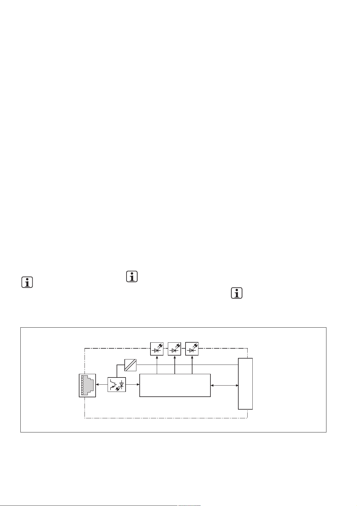
Innenschaltbild
PROFINET
MOD
S TAT
DC
DC
Controller
Internal wiring diagram Schéma interne
- 2 -
COM
S TATACT
PNOZ m1p
Page 3
PNOZ mc9p montieren
Beachten Sie bei der Montage:
Achtung! Durch elektrostatische
Entladung können Bauteile der
Sicherheitssteuerung beschädigt
werden. Sorgen Sie für Entladung,
bevor Sie die Sicherheitssteuerung
berühren, z. B. durch Berühren einer
geerdeten, leitfähigen Fläche oder
durch Tragen eines geerdeten
Armbands.
• Montieren Sie das Sicherheitssystem in
einen Schaltschrank mit einer Schutzart
von mindestens IP54.
• Montieren Sie das Sicherheitssystem auf
eine waagrechte Tragschiene. Die
Lüftungsschlitze müssen nach oben und
unten zeigen (siehe Betriebsanleitung des
Basisgeräts). Andere Einbaulagen können
zur Zerstörung des Sicherheitssystems
führen.
• Befestigen Sie das Sicherheitssystem mit
Hilfe der Rastelemente auf der Rückseite
auf einer Normschiene. Führen Sie das
Sicherheitssystem gerade auf die Normschiene, so dass die Erdungsfedern am
Sicherheitssystem auf die Normschiene
gedrückt werden.
• Um die EMV-Anforderungen einzuhalten,
muss die Normschiene mit dem Schaltschrankgehäuse niederohmig verbunden
sein.
Basisgerät und Erweiterungsmodule
verbinden
Die Module werden mit Steckbrücken
verbunden. Es dürfen max. 8 Erweiterungsmodule und ein Feldbusmodul an ein
Basisgerät angeschlossen werden.
Auf der Geräterückseite des Basisgeräts
befinden sich 2 Stiftleisten.
• Stellen Sie sicher, dass kein Abschlussstecker gesteckt ist.
• Verbinden Sie das Basisgerät, die
Erweiterungsmodule und das Feldbusmodul mit den mitgelieferten Steckbrücken.
• Stecken Sie den Abschlussstecker auf das
letzte Erweiterungsmodul.
• Zwischen dem PNOZ mc9p und externen
Wärmequellen muss mind. 20 mm
Abstand eingehalten werden.
Installing the PNOZ mc9p
Please note for installation:
Caution! Electrostatic discharge can
damage components on the safety
system. Ensure discharge before
touching the safety system, e.g. by
touching an earthed, conductive
surface or by wearing an earthed
armband.
• The safety system should be installed in a
control cabinet with a protection type of at
least IP54.
• Fit the safety system to a horizontal DIN
rail. The venting slots must point up and
down (see operating instructions for the
base unit). Other mounting positions could
damage the safety system.
• Use the notches on the back of the safety
system to attach it to a DIN rail. Connect
the safety system to the DIN rail in an
upright position so that the earthing
springs on the safety system are pressed
on to the DIN rail.
• To comply with EMC requirements, the
DIN rail must have a low impedance
connection to the control cabinet housing.
Connecting the base unit and expansion
modules
The modules are linked via jumpers. A max.
of 8 expansion modules plus one fieldbus
module may be connected to one base unit.
There are 2 pin connectors on the rear of the
base unit.
• Ensure that no terminator is connected.
• Connect the base unit, the expansion
modules and the fieldbus module using the
jumpers supplied.
• The terminator must be fitted to the last
expansion module.
• A distance of at least 20 mm must be
maintained between the PNOZ mc9p and
any external heat sources.
Installer le PNOZ mc9p
Pour le montage, respectez les consignes
suivantes :
Attention ! Une décharge électrostatique peut endommager les éléments
de l’automate de sécurité. Veillez à
vous décharger avant de toucher
l’automate de sécurité, par exemple
en touchant une surface conductrice
mise à la terre ou en portant un
bracelet de mise à la terre.
• Montez le système de sécurité dans une
armoire d’indice de protection IP 54 au
moins.
• Montez le système de sécurité sur un
profilé support horizontal. Les ouïes de
ventilation doivent être orientées vers le
haut et vers le bas (voir le manuel
d’utilisation de l’appareil de base).
D’autres positions de montage pourraient
aboutir à une destruction du système de
sécurité.
• Montez le système de sécurité sur un rail
DIN à l’aide du système de fixation situé
au dos de l’appareil. Installez le système
de sécurité droit sur le rail DIN de sorte
que les ressorts de mise à la terre sur le
système de sécurité reposent sur le rail
DIN.
• Pour répondre aux exigences CEM, le rail
DIN doit être relié au corps de l’armoire
électrique par une liaison à basse
impédance.
Relier l’appareil de base et les modules
d’extension
Les modules sont reliés par des cavaliers de
pontage. Huit modules d’extension et un
module de bus de terrain au maximum
peuvent être reliés à un appareil de base.
La face arrière de l’appareil de base
comporte 2 broches.
• Assurez-vous qu’aucune fiche de terminaison n’est branchée.
• Reliez l’appareil de base, les modules
d’extension et le module de bus de terrain
avec les cavaliers de pontage livrés avec
les appareils.
• Branchez la fiche de terminaison sur le
dernier module d’extension.
• Une distance d’au moins 20 mm doit être
respectée entre le PNOZ mc9p et les
sources de chaleur externes.
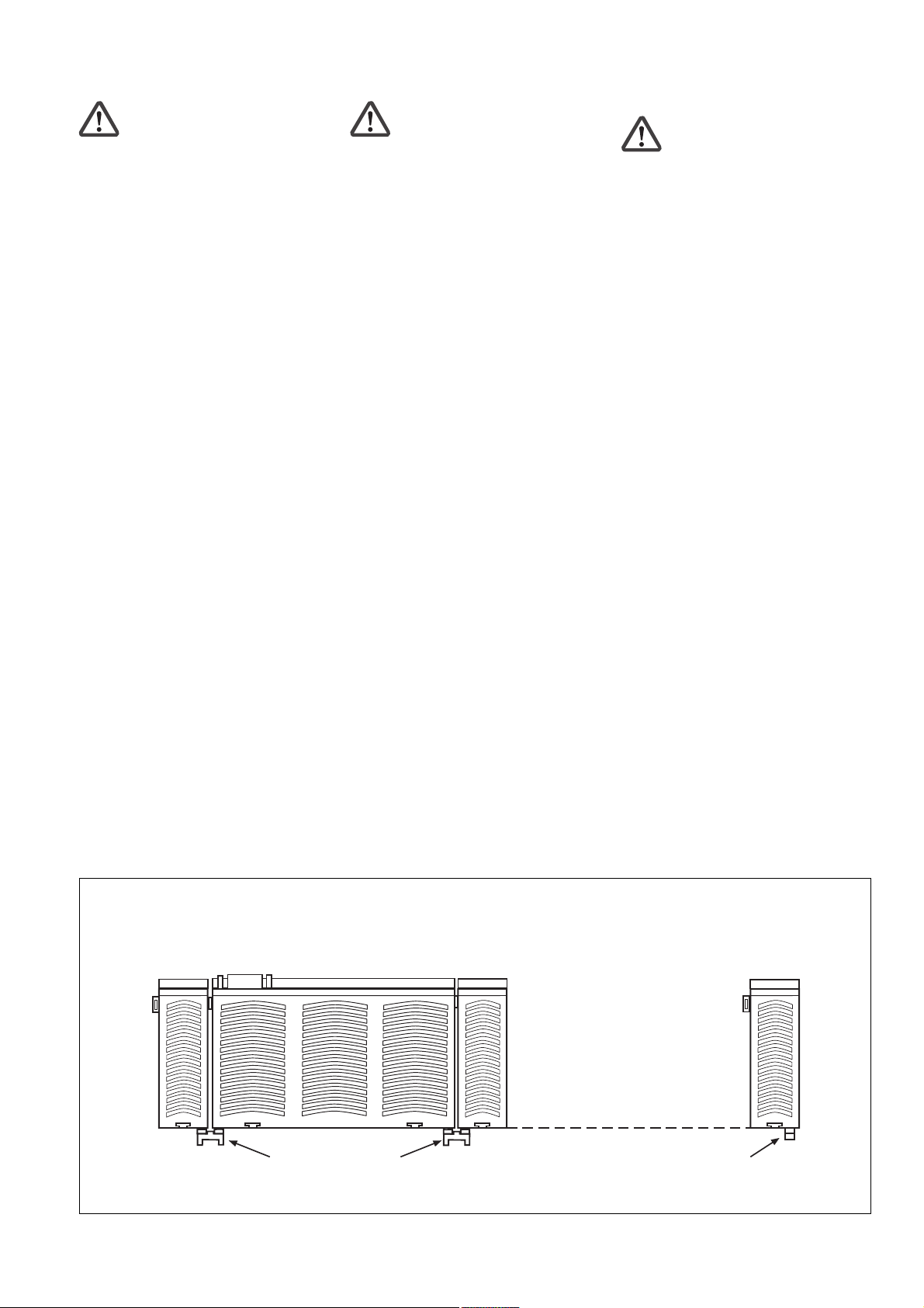
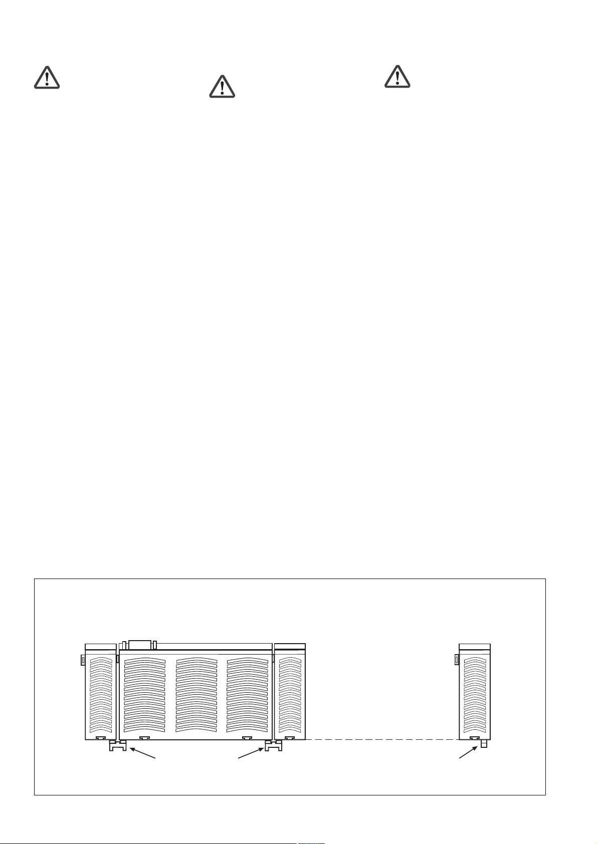
PNOZ mc9p links vom Basisgerät
montieren!
Feldbusmodul
Fieldbus module
Module de bus de terrain
PNOZ mc9p montieren
Install the PNOZ mc9p to the left of the
base unit!
Basisgerät
unit
Base
Appareil de base
Steckbrücke
Jumper
Cavalier de pontage
Installing the PNOZ mc9p Installer le PNOZ mc9p
Erweiterungsmodul 1
Expansion module 1
Module d'extension 1
- 3 -
Monter le PNOZ mc9p à gauche de
l’appareil de base !
Erweiterungsmodul 8
Expansion module 8
Module d'extension 8
Abschlussstecker
Terminator
Fiche de terminaison
Page 4
Achtung! Verwenden Sie nur
Steckbrücken und Abschlussstecker
mit den folgenden Bestellnummern:
Steckbrücken: 774 639
Abschlussstecker: 779 110
Caution! Use only jumpers and
terminators with the following order
numbers:
Jumpers: 774 639
Terminators: 779 110
Attention ! N’utilisez que des
cavaliers de pontage et des fiches de
terminaison portant les références
suivantes :
Cavaliers de pontage : 774 639
Fiches de terminaison : 779 110
PNOZ mc9p inbetriebnehmen
Inbetriebnahme vorbereiten:
Beachten Sie bei der Vorbereitung der
Inbetriebnahme:
Achtung! Das Erweiterungsmodul
PNOZ mc9p nur im spannungslo-
sen Zustand ziehen und stecken.
Wichtig: Beachten Sie bei der
Installation unbedingt die Anforderungen der Installationsrichtlinie
PROFINET der PROFIBUS Nutzerorganisation.
• Die folgenden Mindestanforderungen an
die Verbindungskabel und Stecker müssen
erfüllt werden:
- Verwenden Sie ausschließlich industrie-
taugliche Ethernet-Kabel und Stecker.
- Verwenden Sie ausschließlich doppelt
abgeschirmtes Twisted Pair-Kabel und
geschirmte RJ45-Stecker (IndustrieStecker).
- 100BaseTX-Kabel nach Ethernet-
Standard (min. Kategorie 5)
• Störschutzmaßnahmen
Beachten Sie die Anforderungen für den
industriellen Einsatz von PROFINET IO.
Commissioning the PNOZ mc9p
Preparing for commissioning:
Please note the following when preparing to
commission the unit:
Caution! Only connect and disconnect the PNOZ mc9p expansion
module when the supply voltage is
switched off.
Important: Be sure to note the
PROFIBUS User Group PROFINET
Installation Manual requirements
during installation.
• The following minimum requirements for
connection cables and connectors must be
met:
- Only use standard industrial Ethernet
cable and connectors.
- Only use double-shielded twisted pair
cable and shielded RJ45 connectors
(industrial).
- 10BaseT or 100BaseTX cable in
accordance with the Ethernet standard
(min. Category 5)
• Measures to protect against interference
Ensure the requirements for the industrial
use of PROFINET IO.
Mettre en service le PNOZ mc9p
Préparation de la mise en service :
Pour préparer la mise en service, respectez
les consignes suivantes :
Attention ! Le module d’extension
PNOZ mc9p ne doit être mis en
place ou retiré que lorsqu’il est hors
tension.
Important : Lors de l’installation,
respectez impérativement les exigences indiquées dans la directive
d’installation PROFINET de l’association des utilisateurs PROFIBUS.
• Les exigences minimales posées aux
câbles de raccordement et aux connecteurs doivent être remplies :
- Utilisez exclusivement des câbles et
connecteurs Ethernet prévus pour un
usage industriel.
- Utilisez exclusivement un câble à paires
torsadées à double blindage et des
connecteurs RJ45 blindés (connecteurs
industriels).
- Câble 10BaseT ou 100BaseTX selon la
norme Ethernet (minimum catégorie 5)
• Mesures de protection antiparasitage
Respectez les exigences applicables à
l’utilisation industrielle d’PROFINET IO.
Betriebsbereitschaft herstellen:
• Gerätename vergeben
- Der Gerätename wird im PNOZmulti
Configurator vergeben.
Geben Sie bei der Auswahl des
PNOZ mc9p den Gerätenamen in das
Feld Betriebsmittelkennzeichen ein.
- Sie können den Gerätenamen auch
durch den IO Controller vergeben. In
diesem Fall fügen Sie im PNOZmulti
Configurator vor dem Gerätenamen im
Feld Betriebsmittelkennzeichen das
Zeichen „$“ ein.
- Der Gerätename am Ethernet-Subnetz
muss eindeutig sein. Er muss der DNSKonvention entsprechen:
- max. 127 Zeichen (Buchstaben,
Ziffern, Bindestrich oder Punkt)
- max. 63 Zeichen zwischen zwei
Punkten
- Unzulässig sind Zeichen wie folgt:
ä ö ü ( ) _ / Leerzeichen
Der Gerätename darf nicht
- mit dem Zeichen „-“ beginnen oder
enden.
- die Form n.n.n.n (n = 0 ... 999) haben.
- mit der Zeichenfolge „port-xyz-“ (x, y,
z = 0 ... 9) beginnen.
• GSD-Datei installieren
Installieren Sie die GSD-Datei in Ihrer
Konfigurationssoftware. Erst dann steht
Ihnen das PNOZ mc9p zur Verfügung.
• Legen Sie die Versorgungsspannung an
das Basisgerät:
Klemmen 24 V und A1 (+): + 24 V DC
Klemmen 0 V und A2 (-): 0 V
Preparing for operation:
• Assign unit name
- The unit name is assigned in the
PNOZmulti Configurator.
Enter the unit name in the Equipment
identifier field when selecting the
PNOZ mc9p.
- You can also assign the unit name
through the IO Controller. In this case,
insert a "$" symbol in front of the unit
name in the Equipment identifier field
in the PNOZmulti Configurator.
- The unit name on the Ethernet subnet
must be unique. It must comply with the
DNS conventions:
- max. 127 characters (letters,
numbers, hyphen or period)
- max. 63 characters between two
periods
- the following characters are invalid:
( ) _ / space
The unit name may not
- begin or end with the "-" character.
- have the form n.n.n.n (n = 0 - 999).
- begin with the character string "port-
xyz-" (x, y, z = 0 - 9).
• Install GSD file
Install the GSD file in your configuration
software. You can only then use the
PNOZ mc9p.
• Connect the supply voltage to the base
unit:
Terminals 24 V and A1 (+): + 24 VDC
Terminals 0 V and A2 (-): 0 V
Mise en route :
• Attribuer le nom de l’appareil
- L’attribution du nom de l’appareil
s’effectue dans le PNOZmulti
Configurator.
Lors de la sélection du PNOZ mc9p,
saisissez le nom de l’appareil dans le
champ Identification équipement.
- Vous pouvez également attribuer le nom
de l’appareil à l’aide du IO Controller.
Dans ce cas, tapez le caractère "$"
devant le nom de l’appareil dans le
champ Identification équipement du
PNOZmulti Configurator.
- Le nom de l’appareil sur le sous-réseau
Ethernet doit être unique. Il doit être
conforme à la convention DNS :
- 127 caractères au maximum (lettres,
chiffres, tiret ou point)
- 63 caractères au maximum entre
deux points
- Sont interdits les caractères tels que :
accents ( ) _ / espaces
Le nom de l’appareil ne doit pas
- commencer ou se terminer par le
caractère "-".
- avoir la forme n.n.n.n (n = 0 à 999).
- commencer par la chaîne de caractè-
res "port-xyz-" (x, y, z = 0 à 9).
• Installer le fichier GSD
Installez le fichier GSD dans votre logiciel
de configuration. Le PNOZ mc9p n’est
disponible qu’au terme de ces opérations.
• Appliquez la tension d’alimentation sur
l’appareil de base :
Bornes 24 V et A1 (+) : + 24 V DC
Bornes 0 V et A2 (-) : 0 V
- 4 -
Page 5
• IP-Adresse vergeben
Es bestehen zwei Möglichkeiten:
- Automatische Vergabe der IP-Adresse
mit dem Dynamic Host Configuration
Protocol (DHCP)
- Vergabe der IP-Adresse vom
IO Controller vor dem Systemhochlauf
aufgrund des eindeutigen Gerätenamens.
• Assign IP address
There are two options:
- Automatic assignment of the IP address
with the Dynamic Host Configuration
Protocol (DHCP)
- Assignment of the IP address by the
IO Controller before system startup
based on the unique unit name.
• Attribuer l’adresse IP
Il existe deux possibilités :
- Attribution automatique de l’adresse IP
par le Dynamic Host Configuration
Protocol (DHCP)
- Attribution de l’adresse IP par le
IO Controller avant le démarrage du
système en raison d’un nom d’appareil
unique.
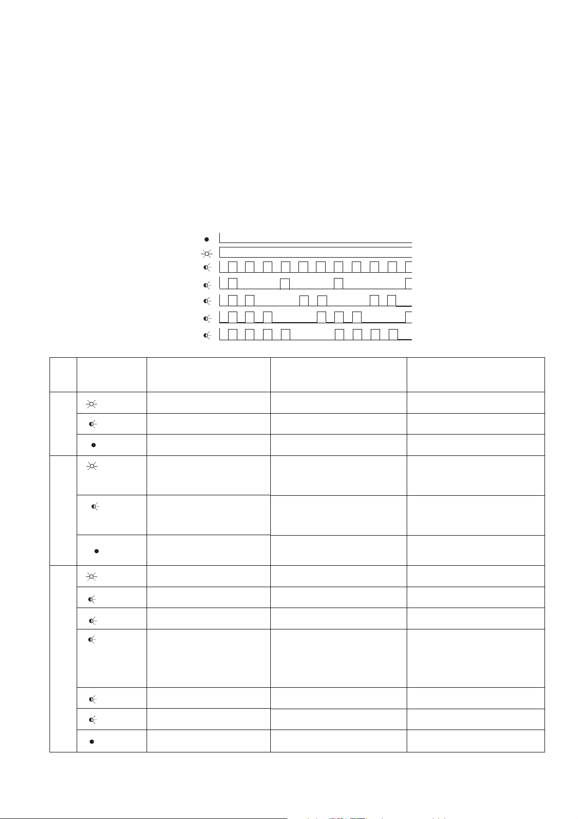
Betrieb
Nach Einschalten der Versorgungsspannung
oder einem Reset des Sicherheitssystems
PNOZmulti wird das PNOZ mc9p automatisch konfiguriert und gestartet. Die LEDS
"ACT", "COM STAT" und "MOD STAT"
zeigen den Status des PNOZ mc9p am
PROFINET IO an.
LED-Anzeige
LED aus/off/éteinte
LED leuchtet/on/allumée
LED blinkt/flashes/clignotante
LED
ACT
COM
STAT
MOD
STAT
LED-Zustand
LED status
état de la LED
grün/green/
vert
grün/green/
vert
grün/green/
vert
grün/green/
1
vert
grün/green/
vert
grün/green/
1
vert
grün/green/
2
vert
rot/red/
1
rouge
rot/red/
3
rouge
rot/red/
4
rouge
Bedeutung
Busverbindung vorhanden
Daten senden/empfangen
keine Busverbindung vorhanden
oder Versorgungsspannung fehlt
Online, Run
- Verbindung mit IO Controller
vorhanden
- IO Controller im Run
Online, STOP
- Verbindung mit IO Controller
vorhanden
- IO Controller im STOP
Offline, STOP
- keineVerbindung mit
IO Controller vorhanden
initialisiert, kein Fehler
Diagnosedaten verfügbar
PNOZ mc9p wird identifiziert
Fehler der Konfiguration
- zu viele Module/Submodule
- I/O-Bereich der IO ControllerKonfiguration ist zu groß
- Fehlerhafte Konfiguration (kein
Modul, falsches Modul)
kein Gerätename oder keine IPAdresse zugewiesen
Interner Fehler
keine Versorgungsspannung oder
Gerät ist nicht initialisiert
Operation
After the supply voltage is switched on or the
PNOZmulti safety system is reset, the PNOZ
mc9p is configured and started automatically.
The "ACT", "COM STAT" and "MOD STAT"
LEDs indicate the status of the PNOZ mc9p
on the PROFINET IO.
LEDs
1
2
3
4
Meaning
Bus connection available
Send/receive data
Bus connection is not available or
supply voltage is missing
Online, RUN
- Connection with IO Controller
available
- IO Controller in RUN
Online, STOP
- Connection with IO Controller
available
- IO Controller in STOP
Offline, STOP
- Connection with IO Controller not
available
Initialised, no fault
Diagnostic data available
PNOZ mc9p is identified
Configuration error
- Too many modules/submodules
- I/O range of IO Controller
configuration is too big
- Faulty configuration (no module,
incorrect module)
No unit name or no IP address
assigned
Internal error
No supply voltage or unit is not
initialised
Fonctionnement
Après application de la tension d’alimentation
ou une réinitialisation du système de sécurité
PNOZmulti, le PNOZ mc9p est automatiquement configuré et démarré. Les LEDs "ACT",
"COM STAT" et "MOD STAT" indiquent l’état
du PNOZ mc9p sur le réseau PROFINET IO.
LEDs de visualisation
Signification
Connexion de bus disponible
Envoi/réception de données
Aucune connexion de bus existante
ou tension d’alimentation manquante
En ligne, Run
- Connexion existante avec
IO Controller
- IO Controller en Run
En ligne, STOP
- Connexion existante avec
IO Controller
- IO Controller en STOP
Hors ligne, STOP
- Aucune connexion existante avec
IO Controller
Initialisé, aucune erreur
Données de diagnostic disponibles
Identification du PNOZ mc9p en cours
Erreur de configuration
- Trop de modules/sous-modules
- La plage I/O de la configuration
IO Controller est trop importante
- Configuration erronée (aucun
module, mauvais module)
Aucun nom d’appareil ou aucune
adresse IP attribué(e)
Erreur interne
Aucune tension d’alimentation ou
appareil non initialisé
- 5 -
Page 6

Datenaustausch
Zur Kommunikation mit dem PNOZmulti
müssen immer 32 Byte gesendet und
empfangen werden. Nur die ersten 20 Byte
werden verwendet (siehe Technischer
Katalog PNOZmulti - Spezielle Anwendungen, Kapitel 2).
Data exchange
32 bytes always must be sent and received
for communication with the PNOZmulti. Only
the first 20 bytes are used (see PNOZmulti
Technical Catalogue - Special Applications,
Chapter 2).
Échange de données
La communication avec le PNOZmulti
s’effectue toujours avec l’envoi et la réception de 32 octets. Seuls les 20 premiers
octets sont utilisés (référez-vous au Catalogue technique PNOZmulti - Applications
spéciales, chapitre 2).
Eingangs- und Ausgangsdaten
Die Daten sind wie folgt aufgebaut:
• Eingangsbereich
Die Eingänge werden im Master definiert
und an das PNOZmulti übergeben. Jeder
Eingang hat eine Nummer, z. B. der
Eingang Bit 4 von Byte 1 hat die Nummer
i12.
• Ausgangsbereich
Die Ausgänge werden im PNOZmulti
Configurator definiert. Jeder verwendete
Ausgang erhält dort eine Nummer, z. B.
o0, o5... Der Zustand des Ausgangs o0
wird in Bit 0 von Byte 0 abgelegt, der
Zustand von Ausgang o5 wird in Bit 5 von
Byte 0 abgelegt usw.
• Nur Ausgangsbereich: Byte 3
Bit 0 ... 4: LED-Zustände des PNOZmulti
- Bit 0: OFAULT
- Bit 1: IFAULT
- Bit 2: FAULT
- Bit 3: DIAG
- Bit 4: RUN
Bit 5: Datenaustausch findet statt.
Zuordnung der Eingänge/ Ausgänge im
PNOZmulti Configurator zu den
PROFINET IO
Eingänge PNOZmulti Configurator/Inputs on PNOZmulti Configurator/Entrées du configurateur PNOZmulti
Eingangsdaten
Ausgänge PNOZmulti Configurator/Outputs on PNOZmulti Configurator/Sorties du configurateur PNOZmulti
Ausgangsdaten
-Ein-/Ausgangsdaten
PROFINET IO
PROFINET IO
/Input data,
/Output data,
Input and output data
The data is structured as follows:
• Input range
The inputs are defined in the master and
transferred to the PNOZmulti. Each input
has a number, e.g. the input bit 4 of byte 1
has the number i12.
• Output range
The outputs are defined in the PNOZmulti
Configurator. Each output that is used is
given a number there, e.g. o0, o5... The
status of output o0 is stored in bit 0 of
byte 0; the status of output o5 is stored in
bit 5 of byte 0 etc.
• Output range only: byte 3
Bit 0 … 4: Status of LEDs on the
PNOZmulti
- Bit 0: OFAULT
- Bit 1: IFAULT
- Bit 2: FAULT
- Bit 3: DIAG
- Bit 4: RUN
Bit 5: Data is being exchanged.
Assignment of the inputs/outputs in the
PNOZmulti Configurator to the
PROFINET IO
PROFINET IO
PROFINET IO
input/output data
/Données d’entrée
/Données de sortie
PROFINET IO
PROFINET IO
Données d’entrée et de sortie
Les données sont structurées de la manière
suivante :
• Plage d’entrées
Les entrées sont définies dans le maître et
transmises au PNOZmulti. Chaque entrée
porte un numéro, par ex. l’entrée bit 4 de
l’octet 1 porte le numéro i12.
• Plage de sorties
Les sorties sont définies dans le
configurateur PNOZmulti. Chaque sortie
utilisée y reçoit un numéro, par ex. o0,
o5... Le bit 0 de l’octet 0 contient l’état de
la sortie o0, le bit 5 de l’octet 0 contient
l’état de la sortie o5 etc.
• Seulement plage de sorties : octet 3
Bit 0 ... 4 : état des LEDs du PNOZmulti
- Bit 0 : OFAULT
- Bit 1 : IFAULT
- Bit 2 : FAULT
- Bit 3 : DIAG
- Bit 4 : RUN
Bit 5 : l’échange de données est en cours.
Affectation des entrées/sorties dans le
configurateur PNOZmulti aux données
d’entrée/de sortie du réseau
I0 ... I7
Byte/Octet 0 :
Bit 0 ... 7
O0 ... O7
Byte/Octet 0 :
Bit 0 ... 7
I8 ... I15
Byte/Octet 1 :
Bit 0 ... 7
O8 ... O15
Byte/Octet 1 :
Bit 0 ... 7
PROFINET IO
I16 ... I23
Byte/Octet 2 :
Bit 0 ... 7
O16 ... O23
Byte/Octet 2 :
Bit 0 ... 7
PROFINET IO-Schnittstelle
Für die Verbindung zum
verfügt das PNOZ mc9p über einen RJ45Anschluss.
Auf den beiden letzten Seiten finden Sie ein
Anschlussbeispiel, die Anschlussbelegung,
die Belegung der
und die Abmessungen des Geräts.
PROFINET IO
PROFINET IO
-Schnittstelle
PROFINET IO interface
The PNOZ mc9p has an RJ45 connection for
connecting to the
The last two pages contain a connection
example, the pin configuration, the configuration of the
unit’s dimensions.
PROFINET IO
PROFINET IO
.
interface and the
Interface PROFINET IO
Pour la connexion au réseau
le PNOZ mc9p dispose d’un raccord RJ45.
Vous trouverez sur les deux dernières pages
un exemple de raccordement, le repérage
des broches, l’affectation de l’interface
PROFINET IO
l’appareil.
ainsi que les dimensions de
PROFINET IO
,
- 6 -
Page 7

Technische Daten
Technical details
Caractéristiques techniques
Elektrische Daten
Versorgungsspannung (UB) über
Basisgerät
Leistungsaufnahme bei U
B
Zeiten
Überbrückung von
Spannungseinbrüchen
PROFINET IO
Anwendungsbereich
Gerätetyp
Statusanzeige
Übertragungsrate
Anschluss
Galvanische Trennung
Prüfspannung
Umweltdaten
Klimabeanspruchung
EMV
Schwingungen nach
Frequenz
Amplitude
Umgebungstemperatur
mit Zwangskonvektion
Lagertemperatur
Mechanische Daten
Schutzart
Einbauraum (z. B. Schaltschrank)
Gehäuse
Klemmenbereich
Normschiene
Hutschiene
Durchzugsbreite
Gehäusematerial
Front
Gehäuse
Abmessungen H x B x T
Gewicht
Electrical data
Supply voltage (UB) via base unit
Power consumption at U
B
Times
Supply interruption before
de-energisation
PROFINET IO
Application range
Device type
Status indicator
Transmission rate
Connection
Galvanic isolation
Test voltage
Environmental data
Climatic suitability
EMC
Vibration to
Frequency
Amplitude
Ambient temperature
with forced convection
Storage temperature
Mechanical data
Protection type
Mounting (e.g. control cabinet)
Housing
Terminals
DIN rail
Top hat rail
Recess width
Housing material
Front panel
Housing
Dimensions H x W x D
Weight
Données électriques
Tension d’alimentation (UB) par
l’appareil de base
Consommation pour U
B
Temps
Insensibilité aux micro-coupures
PROFINET IO
Domaine d’utilisation
Type d’appareil
Affichages de l’état
Vitesse de transmission
Raccordement
Séparation galvanique
Tension de contrôle
Environnement
Sollicitations climatiques
CEM
Vibrations selon
Fréquence
Amplitude
Température d’utilisation
avec convection forcée
Température de stockage
Données mécaniques
Indice de protection
Lieu d’implantation (p. ex. armoire)
Boîtier
Borniers
Rail DIN
Support profilé
Largeur de passage
Matériau du boîtier
Face avant
Boîtier
Dimensions H x L x P
Poids
24 V DC
max.//maxi 2,5 W
min. 20 ms
nicht sicherheitsgerichtete
Anwendungen/non-safetyrelated applications/pour les
applications non dédiées à
la sécurité
Slave//Esclave
LED
100 MBit/s
RJ45
ja/yes/oui
500 V AC
DIN IEC 60068-2-3, 12/86
EN 61000-6-2, 10/01
EN 60068-2-6, 04/95
10 ... 55 Hz
0,35 mm
0 ... + 50 °C
0 ... + 60 °C
-25 ... + 70 °C
IP54
IP20
IP20
35 x 7,5 EN 50022
27 mm
ABS UL 94 V0
PPO UL 94 V0
94 x 22,5 x 119 mm
(3.70" x 0.88" x 4.69")
140 g
Ersatzteile Spares Pièces de rechange
Bezeichnung/Description/Désignation
Steckbrücke/Jumper/Cavalier de pontage
Bestell-Nr./Order no./Référence
774 639
Zubehör siehe techischer Katalog. Accessories, see technical catalogue. Pour les accessoires, voir le catalogue
technique.
- 7 -
Page 8

21 255-01
PNOZ mc9p
4 E Instrucciones de uso
4 I Istruzioni per l`uso
4 NL Gebruiksaanwijzing
Módulo de ampliación PNOZ mc9p
PROFINET IO
El módulo de ampliación PNOZ mc9p puede
ser conectado sólo a un dispositivo base
(p. ej, PNOZ m1p del sistema de seguridad
modular PNOZmulti). Este módulo acopla el
sistema modular de seguridad PNOZmulti a
controles compatibles con el protocolo
PROFINET IO. El sistema de seguridad
modular PNOZmulti sirve para la interrupción, orientada a la seguridad, de circuitos
eléctricos de seguridad y está diseñado para
su empleo en:
• Dispositivos de PARADA DE
EMERGENCIA
• Circuitos de seguridad según VDE 0113
parte 1, 11/98 y EN 60204-1, 12/97
(p. ej. con cubiertas móviles)
Atención: el módulo de ampliación
PNOZ mc9p no debe utilizarse para
funciones orientadas a la seguridad.
Volumen de suministro:
• Módulo de ampliación PNOZ mc9p
• Puente insertable (véase la sección Piezas
de repuesto)
Para su propia seguridad
Tenga en cuenta las siguientes
prescripciones de seguridad:
• Instale y ponga en funcionamiento el
módulo sólo si usted está familiarizado con
estas instrucciones de uso y con las
prescripciones vigentes relativas a la
seguridad en el trabajo y a la prevención
de accidentes.
• Utilice el módulo solo para la aplicación a
la que está destinado. Para ello tenga en
cuenta los valores indicados en la sección
"Datos técnicos".
• Durante el transporte, el almacenaje y el
funcionamiento se deben respetar las
condiciones dispuestas en EN 60068-2-6,
04/95 (véase "Datos técnicos").
• No abra la carcasa ni modifique el aparato
por cuenta propia.
• Desconecte siempre la tensión de
alimentación durante los trabajos de
mantenimiento.
Es estrictamente necesario que observe las
indicaciones de advertencia que se recogen
en las demás secciones de estas instrucciones. Estas indicaciones están resaltadas
gráficamente por medio de símbolos.
Importante: observe las prescripciones de seguridad, en caso contrario se
extingue toda garantía.
Modulo di espansione PNOZ mc9p
PROFINET IO
Il modulo di espansione PNOZ mc9p può
essere collegato solo ad un dispositivo base
(ad es. PNOZ m1p del sistema di sicurezza
modulare PNOZmulti). Collega il sistema di
sicurezza modulare PNOZmulti a sistemi di
comando che supportano il protocollo
PROFINET IO. Il sistema di sicurezza
modulare PNOZmulti viene utilizzato per
l‘interruzione di circuiti elettrici di sicurezza
ed è progettato per l‘utilizzo in:
• dispositivi di arresto di emergenza
• circuiti elettrici di sicurezza conformi alla
norma VDE 0113 Parte 1, 11/98 e
EN 60204-1, 12/97
(p. es. in caso di protezioni mobili)
Attenzione! Il modulo di espansione
PNOZ mc9p non può essere
utilizzato per funzioni di sicurezza.
Materiale della fornitura:
• Modulo di espansione PNOZ mc9p
• Connettore (vedi sezione Pezzi di
ricambio)
Per la Vostra sicurezza
È necessario osservare le seguenti norme di
sicurezza:
• Il modulo può venire installato e messo in
funzione solo se si conoscono bene le
presenti istruzioni per l’uso e le disposizioni vigenti relative alla sicurezza di lavoro e
all’antinfortunistica.
• Utilizzare il modulo solo in base alle
disposizioni ad esso riferite. Osservare
anche i valori indicati al paragrafo "Dati
tecnici".
• Durante il trasporto, l’immagazzinamento e
il funzionamento attenersi alle condizioni
prescritte dalla norma EN 60068-2-6,
04/95, (vedi "Dati tecnici").
• Non aprire la custodia e non apportare
modifiche non autorizzate.
• Assicurarsi di aver interrotto la tensione di
alimentazione prima di procedere ai lavori
di manutenzione.
Osservare le avvertenze riportate nelle altre
sezioni delle presenti istruzioni. Tali indicazioni sono evidenziate da simboli specifici.
Importante: Osservare le disposizioni
per la sicurezza, poiché in caso
contrario decadrà qualsiasi diritto alla
garanzia.
Uitbreidingsmodule PNOZ mc9p
PROFINET IO
De uitbreidingsmodule PNOZ mc9p mag
alleen op een basismodule (b.v. PNOZ m1p
van het modulaire veiligheidssysteem
PNOZmulti) aangesloten worden. De module
koppelt het modulaire veiligheidssysteem
PNOZmulti aan besturingen die het protocol
PROFINET IO ondersteunen. Het modulaire
veiligheidssysteem PNOZmulti dient om
veiligheidscircuits veilig te onderbreken en is
bestemd voor gebruik in:
• noodstopvoorzieningen
• veiligheidscircuits volgens VDE 0113
deel 1, 11/98 en EN 60204-1, 12/97
(b.v. bij beweegbare afschermingen)
Let op! De uitbreidingsmodule PNOZ
mc9p mag niet voor veiligheidsgerelateerde functies gebruikt
worden.
Inbegrepen bij levering:
• Uitbreidingsmodule PNOZ mc9p
• Busconnector (zie paragraaf
Reserveonderdelen)
Voor uw veiligheid
Neem de volgende veiligheidsvoorschriften in
acht:
• Installeer en neem de module alleen in
gebruik, als u vertrouwd bent met deze
gebruiksaanwijzing en de geldende
voorschriften op het gebied van arbeidsveiligheid en ongevallenpreventie.
• Gebruik de module alleen waarvoor hij
bestemd is. Neem daartoe ook de
waarden in de paragraaf "Technische
gegevens" in acht.
• Neem bij transport, opslag en in bedrijf de
richtlijnen volgens EN 60068-2-6, 04/95 in
acht (zie "Technische gegevens").
• Open de behuizing niet en bouw het
apparaat ook niet eigenmachtig om.
• Schakel bij onderhoudswerkzaamheden
altijd de voedingsspanning uit.
Neem altijd de waarschuwingen in de andere
paragrafen in deze gebruiksaanwijzing in
acht. Deze waarschuwingen zijn met
symbolen geaccentueerd.
Belangrijk: Neem de veiligheidsvoorschriften in acht, anders vervalt
elke garantie.
Requisitos del sistema
• Dispositivo base PNOZ m0p
a partir de la versión 2.2
• Dispositivo base PNOZ m1p
a partir de la versión 5.2
• Dispositivo base PNOZ m2p
a partir de la versión 2.2
Requisiti del sistema
• Dispositivo base PNOZ m0p
a partire dalla versione 2.2
• Dispositivo base PNOZ m1p
a partire dalla versione 5.2
• Dispositivo base PNOZ m2p
a partire dalla versione 2.2
- 8 -
Systeemeisen
• Basismodule PNOZ m0p
vanaf Versie 2.2
• Basismodule PNOZ m1p
vanaf Versie 5.2
• Basismodule PNOZ m2p
vanaf Versie 2.2
Page 9

• PNOZmulti Configurator:
a partir de la versión 5.0.0
• Si su versión es anterior, póngase en
contacto con Pilz.
• PNOZmulti Configurator:
a partire dalla versione 5.0.0
• Nel caso si possieda una versione
precedente, rivolgersi a Pilz.
• PNOZmulti Configurator:
vanaf Versie 5.0.0
• Gebruikt u een oudere versie, neem dan
contact op met Pilz.
Descripción del módulo
PROFINET IO está concebido para el rápido
intercambio de datos a nivel de campo. El
módulo de ampliación PNOZ mc9p es un
participante pasivo de PROFINET IO. Las
funciones básicas de la comunicación con
PROFINET IO se corresponden con la
descripción del sistema de la Organización
de usuarios de PROFIBUS.
El control central (master) lee cíclicamente
las informaciones de entrada de los esclavos
y escribe cíclicamente las informaciones de
salida en ellos.
Características del módulo:
• Configurable con PNOZmulti Configurator
• Protocolos de red: PROFINET IO
• Indicadores de estado para la comunicación y para los fallos
• Velocidad de transmisión 100 MBit/s
(100BaseTX), dúplex y semidúplex
Descripción del funcionamiento
Modo de trabajo:
Los datos que se van a transmitir mediante
PROFINET IO son seleccionados y
configurados en el PNOZmulti Configurator.
La conexión entre el dispositivo básico y el
PNOZ mc9p tiene lugar mediante un puente
insertable. Mediante este puente insertable
el PNOZ mc9p recibe también alimentación
de tensión. Después de conectarse la
tensión de alimentación o de un reset del
sistema de seguridad PNOZmulti, el
PNOZ mc9p es automáticamente
configurado y arrancado.
Funciones:
Los LED muestran el estado del módulo de
ampliación PNOZ mc9p en PROFINET IO.
INFORMACIÓN
En la ayuda online del PNOZmulti
Configurator se describe detalladamente la configuración del
PNOZ mc9p.
Descrizione del modulo
PROFINET IO è stato concepito per
consentire uno rapido scambio dei dati a
livello di campo. Il modulo di espansione
PNOZ mc9p è un utente passivo di
PROFINET IO. Le funzioni basilari di
comunicazione con PROFINET IO sono
conformi alla descrizione del sistema
dell’organizzazione degli utenti PROFIBUS.
Il comando centrale (master) legge
ciclicamente le informazioni in ingresso dagli
slave e scrive ciclicamente le informazioni in
uscita verso gli slave.
Caratteristiche del modulo:
• Configurabile con il PNOZmulti
Configurator
•
Protocolli di rete:
• Visualizzazioni di stato per la comunicazione e degli errori
• Velocità di trasmissione 100 MBit/s
(100BaseTX), operatività piena o mezzo
duplex
PROFINET IO
Descrizione del funzionamento
Modalità di lavoro:
I dati da trasmettere tramite PROFINET IO
vengono selezionati e configurati nel
PNOZmulti Configurator.
Il collegamento tra il dispositivo base ed il
PNOZ mc9p avviene tramite un connettore.
Tramite lo stesso connettore viene anche
alimentato il PNOZ mc9p. Dopo l’inserimento
della tensione di alimentazione o in seguito
ad un reset del sistema di sicurezza
PNOZmulti, il PNOZ mc9p viene configurato
e avviato automaticamente.
Funzioni:
I LED indicano lo stato del modulo di
espansione PNOZ mc9p su PROFINET IO.
INFORMAZIONE
Nella guida in linea del PNOZmulti
Configurator la configurazione del
PNOZ mc9p è descritta in maniera
dettagliata.
Modulebeschrijving
PROFINET IO is ontworpen voor het snel
uitwisselen van data op veldniveau. De
uitbreidingsmodule PNOZ mc9p is een
passieve deelnemer van PROFINET IO. De
basisfuncties van de communicatie met
PROFINET IO voldoen aan de systeembeschrijving van de PROFIBUS gebruikersorganisatie.
De centrale besturing (master) leest cyclisch
de ingangsinformatie van de slaves en
schrijft de uitgangsinformatie cyclisch naar
de slaves.
Modulekenmerken:
• Configureerbaar met PNOZmulti
Configurator
• Netwerkprotocollen: PROFINET IO
• Status-LED’s voor communicatie en van
fouten
• Overdrachtssnelheid 100 MBit/s
(100BaseTX), full- en half-duplex
Functiebeschrijving
Werking:
De via PROFINET IO over te dragen data
worden in PNOZmulti Configurator
geselecteerd en geconfigureerd.
De verbinding tussen basismodule en PNOZ
mc9p wordt gerealiseerd via een
busconnector. Via deze busconnector vindt
ook de voeding van PNOZ mc9p plaats. Na
inschakelen van de voedingsspanning of een
reset van het veiligheidssysteem PNOZmulti
wordt PNOZ mc9p automatisch
geconfigureerd en gestart.
Functies:
De status van de uitbreidingsmodule PNOZ
mc9p wordt met LED’s op PROFINET IO
aangegeven.
INFO
In de online hulp van PNOZmulti
Configurator is de configuratie van
PNOZ mc9p uitvoerig beschreven.
PROFINET
Esquema de conexiones internas
MOD
S TAT
DC
DC
Controller
Schema di collegamento interno Intern schema
- 9 -
COM
S TATACT
PNOZ m1p
Page 10
Montar el PNOZ mc9p
Tenga en cuenta durante el montaje:
Atención: los componentes del
sistema programable de seguridad
pueden resultar dañados debido a
una descarga electrostática. Antes
de tocar el sistema de seguridad,
asegúrese de descargar la electricidad estática del cuerpo tocando por
ejemplo una superficie conductora
puesta a tierra o llevando una
muñequera puesta a tierra.
• El sistema de seguridad ha de montarse
en un armario de distribución con un grado
de protección IP54 como mínimo.
• Monte el sistema de seguridad en una
guía portadora horizontal. Las rejillas de
ventilación deben señalar hacia arriba y
hacia abajo (véanse las instrucciones de
uso del dispositivo base). Una posición de
montaje diferente puede provocar la
destrucción del dispositivo.
• Fije el sistema de seguridad a una guía
normalizada con ayuda de los elementos
de encaje en la parte trasera. Coloque el
sistema de seguridad recto sobre la guía
normalizada de tal manera que los
resortes de puesta a tierra del sistema
hagan presión sobre la guía.
• Para cumplir con los requerimientos CEM
la guía debe estar unida, con baja
impedancia, con la carcasa del armario de
distribución.
Conectar el dispositivo base y los
módulos de ampliación
Los módulos se conectan mediante puentes
insertables. Pueden conectarse como
máximo 8 módulos de ampliación y un
módulo de bus de campo en un dispositivo
base.
En la parte posterior del dispositivo base hay
dos clavijeros.
• Asegúrese de que no hay insertado
ningún terminador.
• Conecte el dispositivo base, los módulos
de ampliación y el módulo de bus de
campo mediante los puentes insertables
suministrados.
• Conecte el terminador en el último módulo
de ampliación.
• Entre el PNOZ mc9p y las fuentes de calor
externas debe haber una distancia mínima
de 20 mm.
Montaggio del PNOZ mc9p
In fase di montaggio occorre osservare
quanto segue:
Attenzione! Le scariche
elettrostatiche possono danneggiare
i componenti del comando di
sicurezza. Prestare attenzione ad
evitare scariche nel maneggiare il
sistema di sicurezza, ad es.
mediante una superficie conduttrice
con messa a terra o indossando un
bracciale antistatico.
• Il sistema di sicurezza deve essere
montato in un armadio elettrico con un tipo
di protezione corrispondente almeno al
grado IP54.
• Montare il sistema di sicurezza su una
guida orizzontale. Le feritoie di ventilazione devono essere orientate verso l’alto e
verso il basso (vedi istruzioni per l’uso del
dispositivo base). Posizioni di montaggio
differenti possono provocare la distruzione
del sistema di sicurezza.
• Fissare il sistema di sicurezza su una
guida DIN con l’aiuto degli elementi di
incastro situati sul retro. Applicare il
sistema di sicurezza su una guida DIN
orizzontale, in modo che le molle di messa
a terra presenti sul sistema di sicurezza
facciano presa sulla guida.
• Per rispettare i requisiti di compatibilità
elettromagnetica, la guida deve essere
collegata alla custodia dell’armadio
elettrico con bassa resistenza ohmica.
Collegamento del dispositivo base e dei
moduli di espansione
I moduli vengono collegati con l’ausilio di
connettori. Ad un modulo base è consentito
collegare max. 8 moduli di espansione e un
modulo bus di campo.
Sul retro del dispositivo base sono previste
2 prese.
• Accertarsi che non sia inserito nessun
connettore terminale.
• Collegare il dispositivo base, i moduli di
espansione e il modulo fieldbus con i
connettori in dotazione.
• Collegare il connettore terminale all’ultimo
modulo di espansione.
• Tra il modulo PNOZ mc9p e le fonti di
calore esterne si deve rispettare una
distanza minima di 20 mm.
PNOZ mc9p monteren
Neem bij montage het volgende in acht:
Let op! Door elektrostatische
ontlading kunnen componenten van
de veiligheidsschakeling beschadigd
worden. Zorg voor ontlading voordat
u de veiligheidsschakeling aanraakt,
b.v. door het aanraken van een
geaard, geleidend vlak of door het
dragen van een geaarde armband.
• Monteer het veiligheidssysteem in een
schakelkast met een beschermingsgraad
van minimaal IP54.
• Monteer het veiligheidssysteem op een
horizontale draagrail. De ventilatiegleuven
moeten omhoog en omlaag wijzen (zie de
gebruiksaanwijzing van de basismodule).
Andere inbouwposities kunnen ertoe
leiden dat het veiligheidssysteem defect
raakt.
• Bevestig het veiligheidssysteem op een
DIN-rail met behulp van de relaisvoet op
de achterzijde. Plaats het veiligheidssysteem recht op de DIN-rail, zodat de
aardingsveren van het veiligheidssysteem
op de DIN-rail gedrukt worden.
• Om te voldoen aan de EMC-eisen, moet
de DIN-rail laagohmig met de schakelkastbehuizing verbonden zijn.
Basismodule en uitbreidingsmodulen
verbinden
De modulen worden met busconnectoren
verbonden. Er mogen max. 8 uitbreidingsmodulen en een veldbusmodule op een
basismodule aangesloten worden.
Op de achterzijde van de basismodule
bevinden zich 2 pennenstroken.
• Zorg dat er geen afsluitconnector is
geplaatst.
• Verbind de basismodule en de
uitbreidingsmodulen en de veldbusmodule
met de meegeleverde busconnectoren.
• Plaats de afsluitconnector op de laatste
uitbreidingsmodule.
• Tussen de PNOZ mc9p en externe
warmtebronnen moet ten minste 20 mm
afstand worden aangehouden.
Montar el PNOZ mc9p a la izquierda
del dispositivo base.
Módulo de bus de campo
Modulo bus di campo
Veldbusmodule
Puente insertable
Connettore
Busconnectoren
Montar el PNOZ mc9p
Montare il PNOZ mc9p a sinistra del
dispositivo di base!
Dispositivo base
Dispositivo base
Basismodule
Montaggio del PNOZ mc9p
Módulo de ampliación 1
Modulo di espansione 1
Uitbreidingsmodule 1
- 10 -
PNOZ mc9p links van de basismodule
monteren!
Módulo de ampliación 8
Modulo di espansione 8
Uitbreidingsmodule 8
Terminador
Connettore terminale
Afsluitstekker
PNOZ mc9p monteren
Page 11

Atención: utilice únicamente
puentes insertables y terminadores
con los siguientes números de
pedido:
Puentes insertables: 774 639
Terminadores: 779 110
Attenzione! Utilizzare solo
connettori e connettori terminali con i
seguenti codici di ordinazione:
Connettori: 774 639
Connettore terminale: 779 110
Let op! Gebruik uitsluitend
busconnectoren en
afsluitconnectoren met de volgende
bestelnummers:
Busconnectoren: 774 639
Afsluitconnector: 779 110
Poner en marcha el PNOZ mc9p
Preparativos para la puesta en marcha:
Al preparar la puesta en marcha hay que
tener en cuenta:
Atención: extraer e insertar el
módulo de ampliación PNOZ mc9p
sólo cuando se encuentre sin
tensión.
Importante: durante la instalación,
tenga necesariamente en cuenta los
requerimientos indicados en las
Instrucciones de instalación
PROFINET de la Organización de
usuarios de PROFIBUS.
• Con relación a los cables de conexión y
conectores se deben cumplir los siguientes requisitos mínimos:
- Utilice exclusivamente cables y
conectores Ethernet aptos para
aplicaciones industriales.
- Utilice exclusivamente cables de par
trenzado con doble apantallamiento y
conectores RJ45 apantallados
(conectores aptos para aplicaciones
industriales).
-
Cables 100BaseTX conforme al estándar
Ethernet (mín. categoría 5).
• Medidas de protección contra
interferencias
Observe las condiciones establecidas para
el uso industrial de PROFINET IO.
Preparar el dispositivo para su funcionamiento:
• Asignar el nombre del dispositivo
- El nombre del dispositivo se asigna en
el PNOZmulti Configurator.
Al seleccionar el PNOZ mc9p introduzca
el nombre del dispositivo en el campo
Indicador de equipo.
- También puede asignar el nombre del
dispositivo a través del IO Controller. En
ese caso, agregue en el PNOZmulti
Configurator el signo "$" antes del
nombre del dispositivo, en el campo
Indicador de equipo.
- En la subred Ethernet, el nombre del
dispositivo debe ser inequívoco. Debe
cumplir con la convención DNS:
- máx. 127 caracteres (letras, cifras,
guión o punto)
- máx. 63 caracteres entre dos puntos
- no están permitidos los siguientes
caracteres:
á ñ ¡ ( ) _ / espacio en blanco
El nombre del dispositivo no puede
- comenzar o finalizar con el
carácter "-".
- tener la forma n.n.n.n (n = 0 ... 999).
- comenzar con la cadena de caracteres "port-xyz-" (x, y, z = 0 ... 9).
• Instalar archivo GSD
Instale el archivo GSD en su software de
configuración. Sólo entonces estará
disponible el PNOZ mc9p.
• Conecte la tensión de alimentación en el
dispositivo base:
Bornes 24 V y A1 (+): + 24 V CC
Bornes 0 V y A2 (-): 0 V
Messa in funzione del PNOZ mc9p
Preparazione della messa in funzione:
Durante la preparazione alla messa in
funzione occorre considerare quanto segue:
Attenzione! Inserire e disinserire il
modulo di espansione PNOZ mc9p
soltanto in assenza di tensione.
Importante: In fase di installazione
attenersi ai requisiti richiesti dalla
direttiva sull’installazione di
PROFINET dell’organizzazione degli
utenti PROFIBUS.
• Devono essere rispettati i seguenti requisiti
minimi per cavi di collegamento e
connettori:
- Impiegare esclusivamente cavi e
connettori Ethernet adatti ad applicazioni industriali.
- Impiegare esclusivamente cavi twisted-
pair a doppia schermatura e connettori
RJ45 schermati (connettore industriale).
- Cavi 100BaseTX conformi allo standard
Ethernet
(min. categoria 5)
• Misure di soppressione delle interferenze
Attenersi i requisiti richiesti per l’impiego
industriale di
Preparazione all’uso del dispositivo:
• Assegnare il nome dispositivo
- Il nome del dispositivo viene assegnato
nel PNOZmulti Configurator.
In fase di selezione del PNOZ mc9p
inserire il nome del dispositivo nel
campo Identificativo apparecchiatura.
- È possibile assegnare il nome del
dispositivo anche con IO Controller. In
tal caso inserire nel PNOZmulti
Configurator prima del nome del
dispositivo nel campo Identificativo
apparecchiatura il carattere "$".
- Il nome del dispositivo sulla sottorete
Ethernet deve essere univoco. Deve
essere conforme alla convenzione DNS:
- max. 127 caratteri (lettere, cifre,
- max. 63 caratteri tra due punti
- non sono ammessi caratteri speciali
Il nome dispositivo non deve
- cominciare o terminare con il
- avere la forma n.n.n.n (n = 0 ... 999).
- cominciare con la sequenza di
• Installazione del file GSD
Installare il file GSD nel proprio software di
configurazione. Solo dopo l’installazione il
PNOZ mc9p è disponibile.
• Applicare la tensione di alimentazione al
dispositivo base:
Morsetti 24 V e A1 (+): + 24 V DC
Morsetti 0 V e A2 (-): 0 V
PROFINET IO
lineetta o punto)
come ad esempio:
à é è ò ù ( ) _ / spazi vuoti
carattere "-".
caratteri "port-xyz-" (x, y, z = 0 ... 9).
.
PNOZ mc9p in gebruik nemen
Ingebruikneming voorbereiden:
Neem bij de voorbereiding van de ingebruikneming de volgende zaken in acht:
Let op! De uitbreidingsmodule
PNOZ mc9p alleen in de spannings-
loze toestand uittrekken en plaatsen.
Belangrijk: Neem bij de installatie
altijd de eisen van de installatierichtlijn
PROFINET van de PROFIBUSgebruikersorganisatie in acht.
• Er dient te worden voldaan aan de
volgende minimumeisen aan de
verbindingskabels en stekkers:
- Gebruik uitsluitend voor de industrie
geschikte Ethernet-kabels en stekkers.
- Gebruik uitsluitend dubbel afge-
schermde twisted pair-kabels en
afgeschermde RJ45-stekkers (industriële stekkers).
- 100BaseTX-kabels volgens Ethernet-
norm (min. categorie 5)
• Veiligheidsmaatregelen bij storingen
Houdt u aan de eisen voor het industriële
gebruik van
Bedrijfsklaar maken:
• Apparaatnaam toekennen
- De apparaatnaam wordt toegekend in
PNOZmulti Configurator.
Voer bij het kiezen van de PNOZ mc9p
de apparaatnaam in in het veld
Identificatielabel.
- U kunt de apparaatnaam ook toewijzen
via de IO Controller. Voeg in dit geval in
PNOZmulti Configurator voor de
apparaatnaam in het veld Identificatie-
label het teken "$" toe.
- De apparaatnaam in het Ethernet-
subnet moet eenduidig zijn. Hij moet
overeenstemmen met de DNSconventie:
- max. 127 tekens (letters, cijfers,
- max. 63 tekens tussen twee punten
- Niet toegestaan zijn de volgende
De apparaatnaam mag niet
- met het koppelteken ("-") beginnen of
- de vorm n.n.n.n (n = 0 ... 999)
- met de tekenreeks "port-xyz-"
• GSD-bestand installeren
Installeer het GSD-bestand in uw
configuratiesoftware. Pas daarna kunt u
PNOZ mc9p gebruiken.
• Sluit de voedingsspanning aan op de
basismodule:
klemmen 24 V en A1 (+): + 24 V DC
klemmen 0 V en A2 (-): 0 V
PROFINET IO
koppelteken of punt)
tekens:
ë, é, ï etc., (, ), _, / en spaties
eindigen.
hebben.
(x, y, z = 0 ... 9) beginnen.
.
- 11 -
Page 12
• Asignar dirección IP
Existen dos posibilidades:
- Asignación automática de la dirección
IP con el Dynamic Host Configuration
Protocol (DHCP)
- Asignación de la dirección IP por el
IO Controller antes del arranque del
sistema debido al nombre inequívoco
del dispositivo.
• Assegnazione dell’indirizzo IP
Esistono due possibilità:
- Assegnazione automatica dell’indirizzo
IP con il Dynamic Host Configuration
Protocol (DHCP)
- Assegnazione dell’indirizzo IP
dall’IO Controller prima dell’avvio del
sistema in base al nome dispositivo
univoco.
• IP-adres toekennen
Er zijn twee mogelijkheden:
- Automatische toekenning van het
IP-adres met het Dynamic Host
Configuration Protocol (DHCP)
- Toekennen van het IP-adres door de
IO Controller voor de systeemhoogloop
op basis van de eenduidige apparaatnaam.
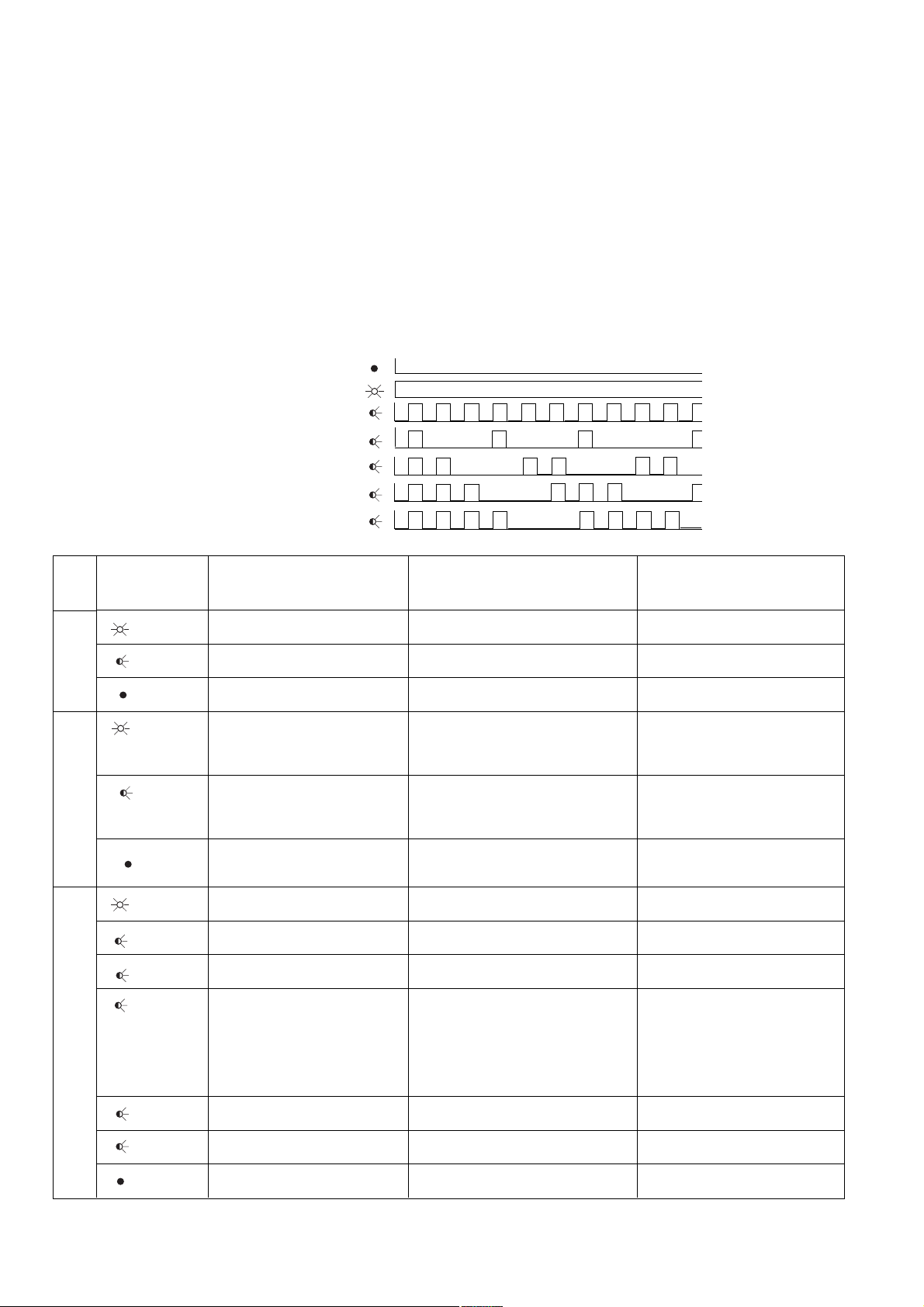
Funcionamiento
Después de conectarse la tensión de
alimentación o de un reset del sistema de
seguridad PNOZmulti, el PNOZ mc9p es
automáticamente configurado y arrancado.
Los LED "ACT", "COM STAT" y "MOD
STAT" muestran el estado del PNOZ mc9p
en PROFINET IO.
Indicador LED
LED apagado/spento/uit
LED encendido/acceso/licht op
LED parpadea/lampeggiante/knippert
LED
ACT
COM
STAT
MOD
STAT
Estado LED
Stato LED
LED-toestand
verde/verde/
groen
verde/verde/
groen
verde/verde/
groen
verde/
1
verde/
groen
verde/verde/
groen
verde/verde/
1
groen
verde/verde/
2
groen
rojo/rosso/
1
rood
rojo/rosso/
3
rood
rojo/rosso/
4
rood
Significado
Conexión de bus disponible
Envío/recepción de datos
No existe conexión de bus o falta
tensión de alimentación
Online, run
- Conexión con el
IO Controller disponible
- IO Controller en run
Online, STOP
- Conexión con el
IO Controller disponible
- IO Controller en STOP
Offline, STOP
- No existe conexión con el
IO Controller
Inicializado, ningún error
Datos de diagnóstico disponibles
El PNOZ mc9p es identificado
Error de configuración
-
Demasiados módulos/submódulos
- Ámbito I/O de la configuración
del IO Controller demasiado
grande
- Configuración errónea (ningún
módulo, módulo erróneo)
No se ha asignado ningún nombre
de dispositivo o dirección IP
Error interno
No hay tensión de alimentación o
dispositivo no instalado
Funzionamento
Dopo l’inserimento della tensione di alimentazione o in seguito ad un reset del sistema
di sicurezza PNOZmulti, il PNOZ mc9p viene
configurato e avviato automaticamente. I
LED "ACT", "COM STAT" e "MOD STAT"
indicano lo stato del PNOZ mc9p su
PROFINET IO.
LED di indicazione
1
2
3
4
Significato
Collegamento bus presente
Inviare/ricevere dati
Mancanza del collegamento bus o
assenza della tensione di alimentazione
Online, Run
- presenza collegamento con
IO Controller
- IO Controller in Run
Online, STOP
- presenza collegamento con
IO Controller
- IO Controller in STOP
Offline, STOP
- assenza collegamento con
IO Controller
Inizializzato, nessuna anomalia
Dati di diagnostica disponibili
Il PNOZ mc9p viene identificato
Errore di configurazione
- troppi moduli/sottomoduli
- il campo I/O della configurazione
IO Controller è troppo grande
- configurazione errata (assenza
modulo, modulo errato)
Assenza nome dispositivo o indirizzo
IP non assegnato
Errore interno
Assenza tensione di alimentazione o
dispositivo non installato
Bedrijf
Na inschakelen van de voedingsspanning of
een reset van het veiligheidssysteem
PNOZmulti wordt PNOZ mc9p automatisch
geconfigureerd en gestart. De LED’s "ACT",
"COM STAT" en "MOD STAT" geven de
status van PNOZ mc9p bij PROFINET IO
weer.
LED’s
Betekenis
Buskoppeling aanwezig
Gegevens verzenden/ontvangen
Geen buskoppeling aanwezig of
ontbrekende voedingsspanning
Online, Run
- Verbinding met IO Controller
aanwezig
- IO Controller in Run
Online, STOP
- Verbinding met IO Controller
aanwezig
- IO Controller in STOP
Offline, STOP
- geen verbinding met IO Controller
aanwezig
Geïnitialiseerd, geen fout
Diagnosegegevens beschikbaar
PNOZ mc9p wordt geïdentificeerd
Fout van de configuratie
- Te veel modulen/submodulen
- I/O-bereik van de IO Controllerconfiguratie is te groot
- Verkeerde configuratie (geen
module, verkeerde module)
Geen apparaatnaam of geen IPadres toegekend
Interne fout
Geen voedingsspanning of apparaat
is niet geïnitialiseerd
- 12 -
Page 13

Intercambio de datos
Para establecer la comunicación con el
PNOZmulti siempre se deben enviar y recibir
32 bytes. Se utilizan sólo los primeros
20 bytes (véase el Catálogo técnico
PNOZmulti - Aplicaciones especiales,
capítulo 2).
Scambio di dati
Per poter comunicare con il PNOZmulti
devono sempre essere inviati e ricevuti 32
byte. Vengono impiegati solo i primi 20 byte
(vedi catalogo tecnico PNOZmulti - Applicazioni speciali, capitolo 2).
Datauitwisseling
Voor communicatie met de PNOZmulti
moeten altijd 32 bytes worden verzonden en
ontvangen. Alleen de eerste 20 Byte worden
gebruikt (zie Technische catalogus
PNOZmulti - Speciale toepassingen,
hoofdstuk 2).
Datos de entrada y de salida
Los datos están estructurados de la siguiente
manera:
• Rango de entrada
Las entradas se definen en el master y se
transmiten al PNOZmulti. Cada entrada
tiene un número, por ejemplo, la entrada
bit 4 del byte 1 tiene el número i12.
• Rango de salida
Las salidas se definen en el PNOZmulti
Configurator. Cada salida utilizada recibe
allí un número, por ejemplo o0, o5 ... El
estado de la salida o0 se almacena en el
bit 0 del byte 0, el estado de la salida o5,
en el bit 5 del byte 0, etc.
• Sólo rango de salida: Byte 3
Bit 0 ... 4: Estados del LED del PNOZmulti
- Bit 0: OFAULT
- Bit 1: IFAULT
- Bit 2: FAULT
- Bit 3: DIAG
- Bit 4: RUN
Bit 5: tiene lugar el intercambio de datos.
Asignación de entradas/salidas en el
PNOZmulti Configurator a los datos de
entrada/salida de PROFINET IO
Entradas del PNOZmulti Configurator/Ingressi PNOZmulti Configurator/Ingangen PNOZmulti Configurator
Datos de entrada de PROFINET IO/Dati di ingresso PROFINET IO/Ingangsdata
PROFINET IO
Salidas del PNOZmulti Configurator/Uscite PNOZmulti Configurator/Uitgangen PNOZmulti Configurator
Datos de salida de PROFINET IO/Dati di uscita PROFINET IO/Uitgangsdata PROFINET IO
Dati d’ingresso e di uscita
I dati sono strutturati nel seguente modo:
• Campo di ingresso
Gli ingressi vengono definiti nel master e
trasmessi al PNOZmulti. Ad ogni ingresso
è assegnato un numero, ad esempio
l’ingresso bit 4 di byte 1 ha il numero i12.
• Campo di uscita
Le uscite vengono definite nel PNOZmulti
Configurator. Ad ogni uscita viene
assegnato un numero, ad es. o0, o5... Lo
stato dell’uscita o0 viene archiviato in bit 0
di byte 0, lo stato dell’uscita o5 in bit 5 di
byte 0 e via dicendo.
• Solo campo di uscita: byte 3:
Bit 0 ... 4: stato dei LED del PNOZmulti
- Bit 0: OFAULT
- Bit 1: IFAULT
- Bit 2: FAULT
- Bit 3: DIAG
- Bit 4: RUN
Bit 5: Ha luogo lo scambio di dati.
Assegnazione degli ingressi/delle uscite
nel PNOZmulti Configurator ai dati in
uscita/ingresso di
PROFINET IO
Ingangs- en uitgangsdata
De data zijn als volgt opgebouwd:
• ingangsbereik
• Uitgangsbereik
• Alleen uitgangsbereik: Byte 3
Toewijzing van de ingangen/uitgangen in
PNOZmulti Configurator aan de
PROFINET IO-in-/uitgangsdata
I0 ... I7
Byte/Octet 0:
Bit 0 ... 7
O0 ... O7
Byte/Octet 0:
Bit 0 ... 7
De ingangen worden in de master
gedefinieerd en overgedragen aan
PNOZmulti. Iedere ingang heeft een
nummer, bijv. ingang bit 4 van byte 1 heeft
nummer i12.
De uitgangen worden in PNOZmulti
Configurator gedefinieerd. Iedere gebruikte uitgang krijgt daarbij een nummer,
bijv. o0, o5... De toestand van de uitgang
o0 wordt in bit 0 van byte 0 opgeslagen; de
toestand van uitgang o5 wordt in bit 5 van
byte 0 opgeslagen etc.
Bit 0 ... 4: LED-toestanden van PNOZmulti
- Bit 0: OFAULT
- Bit 1: IFAULT
- Bit 2: FAULT
- Bit 3: DIAG
- Bit 4: RUN
Bit 5: datauitwisseling vindt plaats.
I8 ... I15
Byte/Octet 1:
Bit 0 ... 7
O8 ... O15
Byte/Octet 1:
Bit 0 ... 7
I16 ... I23
Byte/Octet 2:
Bit 0 ... 7
O16 ... O23
Byte/Octet 2:
Bit 0 ... 7
Interface
El PNOZ mc9p dispone de una conexión
RJ45 para establecer la comunicación con
PROFINET IO.
En las dos últimas páginas encontrará un
ejemplo de conexión, la asignación de
conexiones, la asignación del interface de
PROFINET IO y las dimensiones del
dispositivo.
PROFINET IO
Interfaccia
Per il collegamento a PROFINET IO il
PNOZ mc9p dispone di una presa RJ45.
Nelle ultime due pagine sono riportati un
esempio di collegamento, lo schema di
collegamento, la configurazione
dell’interfaccia PROFINET IO e le dimensioni
del dispositivo.
PROFINET IO
PROFINET IO
Voor de verbinding naar PROFINET IO heeft
PNOZ mc9p een RJ45-aansluiting.
Op de beide laatste pagina’s vindt u een
aansluitvoorbeeld, het aansluitschema, de
bezetting van de PROFINET IO-poort en de
afmetingen van het apparaat.
-poort
- 13 -
Page 14

Datos técnicos
Dati tecnici
Technische gegevens
Datos eléctricos
Tensión de alimentación (UB) a
través del dispositivo base
Consumo de energía con U
Tiempos
Puenteado de caídas de tensión
PROFINET IO
Ámbito de aplicación
Tipo de dispositivo
Indicación de estado
Velocidad de transmisión
Conexión
Separación galvánica
Tensión de prueba
Datos relativos al medio ambiente
Condiciones ambientales
CEM
Oscilaciones según
frecuencia
amplitud
Temperatura ambiente
con convección forzada
Temperatura de almacenaje
Datos mecánicos
Grado de protección
lugar de montaje
(p. ej. armario de distribución)
carcasa
zona de bornes
Riel normalizado
riel de perfil de sombrero
anchura de paso
Material de la carcasa
parte frontal
carcasa
Dimensiones Al x An x Pr
Peso
B
Dati elettrici
Tensione di alimentazione (UB)
mediante dispositivo base
Potenza assorbita con U
Tempi
Ininfluenza mancanza tensione
PROFINET IO
Campo applicativo
Tipo di dispositivo
Visualizzazione di stato
Velocità di trasmissione
Collegamento
Separazione galvanica
Tensione di prova
Dati ambientali
Sollecitazione climatica
CEM
Oscillazioni secondo
Frequenza
Ampiezza
Temperatura ambiente
con convenzione forzata
Temperatura di immagazzinamento
Dati meccanici
Grado di protezione
Spazio di montaggio
(p. es. armadio elettrico)
Custodia
Zona morsetti
Guida DIN
Barra DIN
Larghezza passante
Materiale usato per la custodia
Fronte
Custodia
Dimensioni: altezza x larghezza x
profondità
Peso
B
Elektrische gegevens
Voedingsspanning (UB) via
basismodule
Opgenomen vermogen bij U
Timers
Overbrugging van
spanningsonderbrekingen
PROFINET IO
Toepassingsgebied
Apparaattype
Statusweergave
Overdrachtssnelheid
Aansluiting
Galvanische scheiding
Testspanning
Omgevingscondities
Klimaatcondities
EMC
Trillingen naar
frequentie
amplitude
Omgevingstemperatuur
met geforceerde ventilatie
Opslagtemperatuur
Mechanische gegevens
Beschermingsgraad
Inbouwruimte
(b.v. schakelkast)
Behuizing
Aansluitklemmen
DIN-rail
Rail
Doortrekbreedte:
Behuizingsmateriaal
Front
Behuizing
Afmetingen h x b x d
Gewicht
24 V DC
B
máx./max./Max. 2,5 W
mín./min./Min. 20 ms
aplicaciones no orientadas
a la seguridad/applicazioni
non di sicurezza/Nietveiligheidsgerelateerde
toepassingen
Esclavo/Slave/Slave
LED
100 MBit/s
RJ45
sí/sì/ja
500 V AC
DIN IEC 60068-2-3, 12/86
EN 61000-6-2, 10/01
EN 60068-2-6, 04/95
10 ... 55 Hz
0,35 mm
0 ... + 50 °C
0 ... + 60 °C
-25 ... + 70 °C
IP54
IP20
IP20
35 x 7,5 EN 50022
27 mm
ABS UL 94 V0
PPO UL 94 V0
94 x 22,5 x 119 mm
(3.70" x 0,88" x 4.69")
140 g
Piezas de repuesto
Denominación/Denominazione/Benaming
Puente insertable/Connettore/Busconnector
Para los accesorios, véase el catálogo
técnico.
Ricambi
Per gli accessori, vedi il catalogo
tecnico.
- 14 -
Reserveonderdelen
Pedido n°/N. ordinazione/Bestelnr.
774 639
Zie voor toebehoren Technische
catalogus.
Page 15

PROFINET IO-Schnittstelle
DD
D
DD
Interface PROFINET IO Interfaccia PROFINET IO
EE
E
EE
GBGB
GB
GBGB
II
I
II
PROFINET IO interface
PROFINET IO Interface
FF
F
FF
NLNL
NL
PROFINET IO-
NLNL
communicatiepoort
RJ45-Buchse
8-polig/
RJ45 socket
8-pin/
Connecteur RJ45
à 8 broches/
Conector hembra RJ45
8 polos/
Presa RJ45
8 poli/
RJ45-bus
8-polig
Anschlussbeispiel
DD
D
DD
Der Betrieb an PROFINET IO erfolgt durch
Anschluss an einen Sternverteiler (Hub,
Switch). Der Anschluss an einen Sternverteiler erfordert ein Patch-Kabel
(ungekreuzte Verbindung der Datenleitungen).
EE
Ejemplo de conexión
E
EE
El funcionamiento en PROFINET IO se lleva
a cabo mediante la conexión de un distribuidor de red, ya sea puente o repetidor
multipuerto (hub, switch). Para realizar la
conexión a un distribuidor de red se necesita un cable patch (conexión no trenzada de
las líneas de datos).
81
n.c. = nicht angeschlossen
n.c. = not connected
n.c. = non raccordé
n.c. = no conectado
n.c. = non connesso
n.c. = niet gebruikt
Connection example
GBGB
GB
GBGB
Operation on PROFINET IO occurs through
connection to a hub (hub, switch). To
connect to a hub you will need a patch cable
(uncrossed data line connection).
II
Esempio di collegamento
I
II
Il funzionamento con PROFINET IO avviene
tramite collegamento ad un hub (hub/
switch). Per il collegamento all'hub è
necessario un cavo patch (collegamento
non incrociato delle linee dati).
Standard
PIN
TD+ (Transmit+)
1
TD- (Transmit-)
2
RD+ (Receive+)
3
n.c.
4
n.c.
5
RD- (Receive-)
6
n.c.
7
n.c.
8
Exemple de raccordement
FF
F
FF
Le fonctionnement sur un réseau
PROFINET IO se fait par le raccordement à
un répartiteur en étoile (hub, switch). Le
raccordement à un répartiteur en étoile
exige un câble droit (connexion non croisée
des câbles de données).
NLNL
NL
NLNL
Aansluitvoorbeeld
Het gebruik van PROFINET IO wordt
gerealiseerd door aansluiting op een hub of
een switch. Voor aansluiting op een
sternetwerk is een patchkabel nodig
(ongekruiste verbinding van de datakabels).
PROFINET
Hub/Switch
PROFINET-Teilnehmer
PROFINET subscriber
Abonné PROFINET
Participante PROFINET
Utente PROFINET
PROFINET deelnemer
773731
Hub/Switch
- 15 -
Page 16

4D Abmessungen in mm (")
4E
Dimensiones en mm (") 4I Dimensioni in mm (")
4GB Dimensions in mm (")
4F Dimensions en mm (")
4NL Afmetingen in mm (")
114 (4.49")
94 (3.70")
4D Anschlussbelegung
4E
Asignación de conexiones 4I Schema delle connessioni
4GB Connector pin assignment
773731
22,5
(0.88")
4F Affectation des raccords
4NL Klembezetting
A
Pilz Ges.m.b.H., ✆ 01 7986263-0, Fax: 01 7986264, E-Mail: pilz@pilz.at
safety@pilz.com.au
E-Mail: pilz@pilzbr.com.br
✆
74436332, Fax: 74436342, E-Mail: pilz@pilz.dk
Electronic,
pilz.fi@pilz.dk
Fax: 031 789555, E-Mail: info@pilz.it
Ltd.,
✆
045 471-2281, Fax: 045 471-2283, E-Mail: pilz@pilz.co.jp
info@mx.pilz.com
352, E-Mail: t.catterson@pilz.co.nz
Office,
✆
021 62494658, Fax: 021 62491300,
SE
Pilz Skandinavien K/S, ✆ 0300 13990, Fax: 0300 30740, E-Mail: pilz.se@pilz.dk
✆
0224 2360180, Fax: 0224 2360184, E-Mail: pilz.tr@pilz.de
info@pilzusa.com
www
www.pilz.com
D
Pilz GmbH & Co. KG, Sichere Automation, Felix-Wankel-Straße 2, 73760 Ostfildern, Deutschland, ✆ +49 711 3409-0, Fax: +49 711 3409-133,
E-Mail: pilz.gmbh@pilz.de
B L
✆
03 88104000, Fax: 03 88108000, E-Mail: siege@pilz-france.fr
GB
Pilz Belgium, ✆ 09 3217570, Fax: 09 3217571, E-Mail: info@pilz.be
CH
Pilz lndustrieelektronik GmbH, ✆ 062 88979-30, Fax: 062 88979-40, E-Mail: pilz@pilz.ch
Pilz Automation Technology, ✆ 01536 460766, Fax: 01536 460866, E-Mail: sales@pilz.co.uk
IRL
E
Pilz lndustrieelektronik S.L., ✆ 938497433, Fax: 938497544, E-Mail: pilz@pilz.es
Pilz Ireland Industrial Automation, ✆ 021 4346535, Fax: 021 4804994, E-Mail: sales@pilz.ie
MEX
NL
Pilz Nederland, ✆ 0347 320477, Fax: 0347 320485, E-Mail: info@pilz.nl
P
Pilz Industrieelektronik S.L., ✆ 229407594, Fax: 229407595, E-Mail: pilz@pilz.es
E-Mail: sales@pilz.com.cn
USA
AUS
Pilz Australia, ✆ 03 95446300, Fax: 03 95446311, E-Mail:
BR
Pilz do Brasil, ✆ 11 4337-1241, Fax: 11 4337-1242,
DK
FIN
Pilz Skandinavien K/S, ✆ 09 27093700, Fax: 09 27093709, E-Mail:
Pilz de Mexico, S. de R.L. de C.V., ✆ 55 5572 1300, Fax: 55 5572 4194, E-Mail:
NZ
I
Pilz ltalia Srl, ✆ 031 789511,
Pilz New Zealand, ✆ 09- 6345-350, Fax: 09-6345-
PRC
ROK
Pilz Automation Safety L.P., ✆ 734 354-0272, Fax: 734 354-3355, E-Mail:
Pilz Korea, ✆ 031 8159541, Fax: 031 8159542, E-Mail: info@pilzkorea.co.kr
TR
Pilz Elektronik Güvenlik Ürünleri ve Hizmetleri Tic. Ltd. ¸Sti.,
- 16 -
Pilz Skandinavien K/S,
F
Pilz France
J
Pilz Japan Co.,
Pilz China Representative
21 255-01, 2006-11 Printed in Germany
 Loading...