


Road Gear 160 
 Road Gear 260

Integrated Mobile Sound System Sistema de Sonido Móvil Integrado
English / Español /
User’s Manual Manual del Usuario

Road Gear 160 
 Road Gear 260

Integrated Mobile Sound System Sistema de Sonido Móvil Integrado
CONTENTS |
CONTENIDO |
|
INTRODUCTION........................ |
4 |
FEATURES................................. |
4 |
ROADGEAR COMPONENTS..... |
4 |
disassembling...................... |
5 |
initial setup........................... |
5 |
THE ROADGEAR MIXER........... |
6 |
COMBINATION DOCKING |
|
LOCK.......................................... |
9 |
THE ROADGEAR SPEAKERS... |
9 |
MICROPHONE........................... |
9 |
OPTIONAL ACCESSORIES..... |
10 |
SPECIFICATIONS.................... |
11 |
APPLICATION.......................... |
28 |
BLOCK DIAGRAMS................. |
29 |
..............................INTRODUCCION |
13 |
............................... |
22 |
CARACTERISTICAS........................ |
13 |
............................... |
22 |
Componentes de Road GeaR..13 |
RoadGear ............... |
22 |
|
Desmontaje................................. |
14 |
............................... |
23 |
Configuración Inicial.............. |
14 |
........................ |
23 |
Mezcladora RoadGear............ |
15 |
RoadGear ........... |
23 |
Combinación de Cierre de |
|
..................... |
25 |
Atracamiento............................. |
18 |
RoadGear ............... |
26 |
Altavoces de RoadGear.......... |
18 |
............................ |
26 |
Microfono................................... |
18 |
........................ |
26 |
Accesorios Opcionales.......... |
19 |
............................... |
27 |
ESPECIFICACIONES....................... |
20 |
............................... |
28 |
APLICACION.................................... |
28 |
............................ |
29 |
DIAGRAMAS DE BLOQUE.............. |
29 |
|
|
|
|
|
|
Phonic preserves the right to improve or alter any information within this document without prior notice Phonic se reserva el derecho de mejorar o alterar cualquier información provista dentro de este documento sin previo aviso PHONIC
V1.0 12/05/2008
IMPORTANT SAFETY INSTRUCTIONS
The apparatus shall not be exposed to dripping or splashing and that no objects |
|
|
|
with liquids, such as vases, |
|
|
|||
|
|
shall be placed on the apparatus. The MAINS plug is used as the disconnect device, the disconnect device shall remain readily operable.
Warning: the user shall not place this apparatus in the 


 area during the operation so that the mains switch can be easily accessible.
1.Read these instructions before operating this apparatus.
2.Keep these instructions for future reference.
3.Heed all warnings to ensure safe operation.
4.Follow all instructions provided in this document.
5.Do not use this apparatus near water or in locations where condensation may occur.
6.Clean only with dry cloth. Do not use aerosol or liquid cleaners. Unplug this apparatus before cleaning.
7.Do not block any of the ventilation openings. Install in accordance with the manufacturer’s instructions.
8.Do not install near any heat sources such as radiators, heat registers, stoves, or other apparatus (including 


 .
.
9.Do not defeat the safety purpose of the polarized or grounding-type plug. A polarized plug has two blades with one wider than the other. A grounding type plug has two blades and a third grounding prong. The wide blade or the third prong is provided for your safety. If the provided plug does not  into your outlet, consult an electrician for replacement of the obsolete outlet.
10.Protect the power cord from being walked on or pinched particularly at plug, convenience receptacles, and the point where they exit from the apparatus.
11.Only use attachments/accessories 


 by the manufacturer.
12.Use only with a cart, stand, tripod, bracket, or
table 


 by the manufacturer, or sold with the apparatus. When a cart is used, use caution when moving the cart/apparatus
combination to avoid injury from tipover.
13.Unplug this apparatus during lighting storms or when unused for long periods of time.
14.Refer all servicing to 


 service personnel. Servicing is required when the apparatus has been damaged in any way, such as power-supply cord or plug is damaged, liquid has been spilled or objects have fallen into the apparatus, the apparatus has been exposed to rain or moisture, does not operate normally, or has been dropped.
CAUTION |
RISK OF ELECTRIC SHOCK |
DO NOT OPEN |
CAUTION: TO REDUCE THE RISK OF ElECTRIC SHOCK, |
DO NOT REMOvE COvER (OR bACK) |
NO USER SERvICEAblE PARTS INSIDE |
REFER SERvICING TO QUAlIFIED PERSONNEl |
The lightning flash with arrowhead symbol, within an equilateral triangle, is intended to alert the user to the presence of uninsulated “dangerous voltage” within the product’ 


magnitude to constitute a risk of electric shock to persons.
The exclamation point within an equilateral triangle is intended to alert the user to the presence of important operating and maintenance (servicing) instructions in the literature accompanying the appliance.
WARNING: To reduce the risk of or electric shock, do not expose this apparatus to rain or moisture.
CAUTION: Use of controls or adjustments or performance of procedures other than those 


 may result in hazardous radiation exposure.
Introduction
We at Phonic would like to congratulate you on purchasing one of the RoadGear Plus mobile audio systems, a set of audio equipment superior in design and versatility. The Phonic RoadGear sets allow you to take all the equipment you need to setup an advanced all-in-one integrated sound system anywhere you go, with a minimum of fuss. The fully self-contained unit includes two full-range speakers, a powered mixer, and two dynamic microphones, as well as all the needed cables. RoadGear also gives you the option of using wireless microphones and supplies enough storage space to pack them conveniently away.
Setting up the RoadGear couldn’t be easier. Just release the docking lock, and, after disassembling the mobile kit, simply position the speakers, and plug them, the microphone, and any other instruments or devices you wish, into the powered mixer. After plugging the powered mixer into an appropriate power supply, your system is ready to use. Not only is it this simple to set up, however, but using the system is just as simple. Using the controls of the supplied powered mixer, simply adjust the levels of the inputs, as well as the high, low, and middle frequencies of the inputs, and the digital effects processor. All these features make the RoadGear an easy and convenient solution to a mobile sound system.
This user’s manual is specifically designed to give you accurate information on the function and use of the RoadGear 160 Plus and RoadGear 260 Plus. After thoroughly reading this manual, it is suggested you store it in an easily accessible place for future reference.
RoadGear 260 Plus additional features
●260 Watt (130 per channel) stereo
●Six input channel mixer: four mic/line, two stereo
●High-Definition digital effect processor with 16 programs and tap-delay
●3-band system equalizer
●Two dynamic microphones (with clips, cables and individual pouches)
RoadGear Components
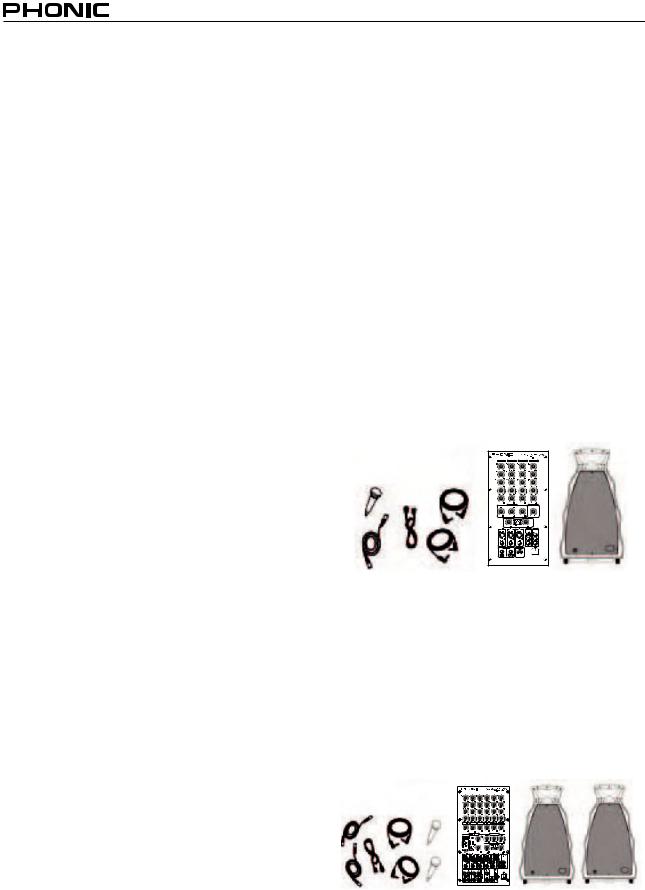
RoadGear 160 Plus
●Two Speakers with specially molded enclosures
●One powered mixer built into a specially molded storage case
●One Phonic UM 99 microphone with 16 foot (5 meter) cable, clip and carry pouch
●Two 30 foot (9 meter) speaker cables
●Detatchable power cable
●One transparent dust cover
Features
Common Features
●Integrated mobile sound system with luxury luggage-style molded cabinet plus wheels
●Operates on AC or DC power
●Speaker system with 1” compression driver and 8” woofer
●2-band EQ on each input channel
●Two 30 feet speaker cables
●Two receiver slots for optional wireless microphones
●Storage compartment for microphones, cables and accessories
RoadGear 160 Plus additional features
●160 Watt (80 per channel) stereo
●Four input channel mixer: three mic/line and one stereo
●Echo effect with delay time and repeat controls
●System equalizer with treble/bass control
●One dynamic microphone (with mic clip, cable and carry pouch)
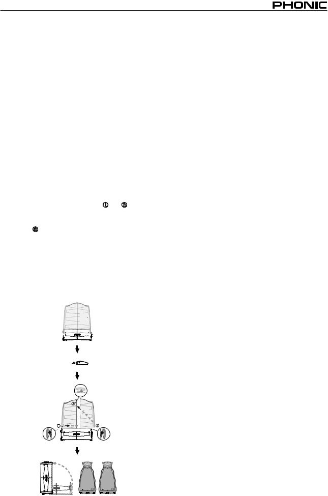
RoadGear 260 Plus
●Two Speakers with specially molded enclosures
●One powered mixer built into a specially molded storage case
●Two Phonic UM 99 microphones each with 16 foot (5 meter) cable, clip and carry pouch
●Two 30 foot (9 meter) speaker cables
●Detatchable power cable
●One transparent dust cover
Road Gear 160 Plus/Road Gear 260 Plus
Caution 
●Use the AC power cable supplied with the RoadGear sets only
●When buying the RoadGear, the AC power cable will be specific to the safety and code requirements of the Country of purchase
●The ground (earth) pin of the AC power cable’s male connector should under no circumstances be removed.
●When taking the RoadGear abroad, check local voltage levels and ensure the appropriate power standard is used, as selected by the power selection switch on the rear panel.
●When the RoadGear is in use, the storage compartment door much be kept open for better ventilation
Dissassembling
To follow is the most convenient way to open and close the RoadGear kits. Following these instructions will ensure trou- ble-free setup of the RoadGear.
1.You should first unclip docking locks and (indicated below) on the either side of the RoadGear.
2.After unlocking these docking locks you can then open the top lock . This ensure the RoadGear pieces come apart smoothly.
3.Stand the powered mixer upright.
4.To re-assemble the RoadGear pieces, the same order should be taken (side locks first, followed by the top).This way the pieces will be held securely and firmly together.
5.When using the RoadGear speakers, ensure that the docking locks on the rear are locked back into place, to ensure they don’t scratch the surface on which they sit.
Push botton in to release lock
1
Initial Setup
Please ensure you take note of all setup instructions listed in this manual. The RoadGear 160 and 260 are both used as normal PA systems and therefore all care should be taken in ensuring the correct setting up of equipment.
1.Disassembling the mobile RoadGear set and remove the speakers from the top of the kit. Remove all items you wish to use in your PA system from the RoadGear’s storage area. Also, place the mixer and speakers in a suitable place.
2.Contect the two speakers to the Powered Mixer, via the supplied speaker cable. An optional speaker stand may be used to increase the height of the speakers.
NB. No devices other than speakers should be connected to the speaker outputs. Doing so will likely cause damage to the device. Also, guitar should not be used to connect amplifiers to speakers.
3.Plug all necessary instruments and equipment into the device’s various inputs as required. This may include linesignal devices, as well as microphones and/or guitars, keyboards, ect.
4.Plug any necessary equipment into the device’s various outputs. This could include monitors, signal processors, and/or recording devices.
5.Ensure all input and out levels are set to the leftmost position.
6.Plug the supplied AC cable into the AC inlet on the back of the RoadGear mixer.
NB. Ensure the power cable has no scratches or cuts that may reveal the wire beneath before plugging into the provided powered mixer as constant setting up and disassembling of equipment may cause insulation wear.
7.Plug the supplied AC cable into a power outlet of a suitable voltage.
8.Turn the mixer power switch to the on position and set all input and output at appropriate levels to suit your needs.
9.When the RoadGear is in use, the storage compartment door must be kept open for better ventilation.
Road Gear 160 Plus/Road Gear 260 Plus
The RoadGear Mixer
The powered mixer provided with the RoadGear 260 Plus is equipped with 4 mono microphone and line inputs, as well as 2 stereo inputs and a built in effect processor boasting a 32/40bit DSP. All this, plus a 3-band built in equalizer, ensures your audio always sounds great on the road.
The RoadGear 160 Plus’s mixer is equipped with 3 mono mic and line inputs, a single stereo channel, built-in digital echo and system bass/treble control.
Making a Connection

 4
4
3 4 6
RoadGear260 |
RoadGear160 |
|
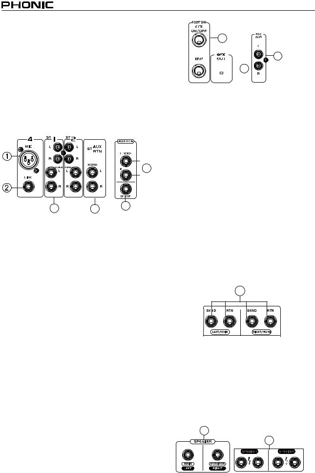
1. Microphone Input Jacks
These XLR jacks are for the input of low level signal devices, most commonly, microphones. For best performance, we suggest using the microphones supplied with the RoadGear set, however they can be used in conjunction with any professional condenser, dynamic (RoadGear 260 Plus only) or ribbon microphones with standard 3-pin XLR male connectors.
2. Line Input Jack
These 1/4” TS phone jacks accept a wide range of input line level devices, such as guitars and keyboards. It can accept unbalanced sources, however any microphones plugged into the microphone input will not work when a line device is attached to this system.
3. Stereo Inputs
The stereo inputs include 2 sets of jacks: standard RCA stereo jacks, for use with consumer gear like CD and tape players, etc., and stereo 1/4” TS phone jacks, for use with stereo products such as keyboards and drum machines. The RCA and TS jacks can both be used simultaneously; however, in some cases this is unadvisable as the blending of audio may have undesirable results. The audio fed into these input are fed to the corresponding stereo input bus.
4. Stereo AUX Return
These TS inputs connect the mixer with parallel external devices, such as sub mixers or external effect processors, receiving the processed signal from another source and feed it to the main mixing bus. If you wish to use a signal from a mono device, simply connect the input to the left jack, and the signal will be doubled to the right, effectively making it a mono signal.
7
5

 6
6
5. Record Out
These outputs will accommodate RCA cables to be fed to a variety of recording devices, such as tape and digital recorders.
6. Effects (EFX) Out
These 1/4” TS outputs are the final output from the effects send mixing bus. This feed may be used to connect to an amplifier and speakers, or to external digital effect processors.
When using external processors, the feed can be returned to the Stereo AUX Return ports.
7. Foot Switch (RoadGear 260 Plus only)
This port allows the inclusion of a foot switch for remote alteration of digital effect properties (on or off). The upper one is for turning on and off effect; the lower one is for changing tap delay.
8. Send and Return (RoadGear 260 Plus)
These connectors allow external signal processors to be incorporated with the main mix, just prior to being sent through the power amplifier. Devices that can be used in conjunction with these jacks include graphic equalizers, digital effect processors, feedback silencers, and so forth. It is strongly advised that these devices are set at low levels to ensure the RoadGear’s inputs do not overload.
8
9. Speaker Outputs
These jacks are used to connect to speakers, fed from the internal power amplifier. Both sets of outputs are 1/4” TS jacks, whichcandrive130Wattsofoutputinto8Ω(or80Wattsinto8Ω on the RoadGear 160 Plus) per channel. To use these, simply insert an appropriate 1/4” TS plug into them. The RoadGear 260 Plus features 2 speaker outputs per channel, whereas the RoadGear 160 Plus features a single output per channel.
NB. Due to the fact that the output signal of these jacks is active, they should be used in conjunction with speakers only as to avoid damaging any other equipment.
9
9
RoadGear 160 Plus |
RoadGear260 Plus |
Road Gear 160 Plus/Road Gear 260 Plus

Controls and Settings
10. High Frequency Control
This control alters the degree of high frequencies – or treble – in the audio of the corresponding channel. Turn clockwise to increase the amount of treble in the sound, and turn counterclockwise to decrease the amount. Position the knob for a flat response, if not in use.
11. Low Frequency Control
This control alters the degree of high frequencies – or bass – in the audio of the corresponding channel. Turn clockwise to increase the amount of bass in the sound, and turn counterclockwise to decrease the amount. Position the knob at “0” if not in use.
10 |
11 |
12 |
13 |
14 |
12. MONI / EFX Control
This control adjusts the signal level of the corresponding channel to be sent to the EFX and Monitor mixing bus, for digital effect processing and monitoring of audio, respectively.
13. PAN / BAL Control
The ‘pan’ control alternates the degree or level of the mono audio signal that the left and right channels of the main mix should receive. On stereo channels, the ‘Balance’ attenuates the left or right signal as required.
14. Level Control
This control alters the signal level of the corresponding channel to the main mix of the RoadGear. This control should be set at “0” when the mixer is not in use.
Digital Effects (RoadGear 160 Plus)
15. Time Control
This control adjusts the time of the built-in echo effect.
16. Repeat Control
This control adjusts the frequency of the repeats in the Echo effect.
17. Level Control
This control adjusts the amount of the audio from the built-in Echo effect processor that will be sent to the main mix.
15 |
16 |
17 |
Digital Effects Panel (RoadGear 260 Plus)
19 |
22 |
18 |
20 |
|
21 |
18. Digital Effects Panel
This 2-digital numeric display shows the program number that is currently applied to your EFX audio signal. When you rotate the Program control, you can scroll through different program numbers; however the display will revert back to the original program if a new program is not selected within a few seconds.
19. Sig and Clip Indicators
Located within the Digital Effect Display are Clip and Sig LEDs. The Sig LED will light up when any signal is received by the effect processor, and the Clip LED will light up shortly before excessive signals are dynamically clipped. If the Clip LED lights up too often, it may be advisable to turn down one or all EFX controls on input channels to ensure the signal level is not too high.
20. Program Control
This control is used to scroll through the various effects. Turning the control clockwise will allow users to ascend into higher program numbers, and turning it counter-clockwise will allow users to descend into lower program numbers. Pushing this control will apply the new effect. When a tap-delay effect is selected, pressing this control will allow users to select the tapdelay time.
By pushing the button several times, the effect processor interprets the time between last two pushes and remembers this as the delay time, until the button is pushed again (this is kept, even after the power is turned off). When the tap delay effect is selected, a small LED will flash within the digital effect display window at the selected intervals.
21. EFX Master Control
The EFX master control adjusts the final level of the processed signal that is sent to the main mix.
22. Bypass Switch
Pushing this switch will bypass the effect engine. Two small indicators within the Effects display will flash when this is done.
Road Gear 160 Plus/Road Gear 260 Plus
Master Controls
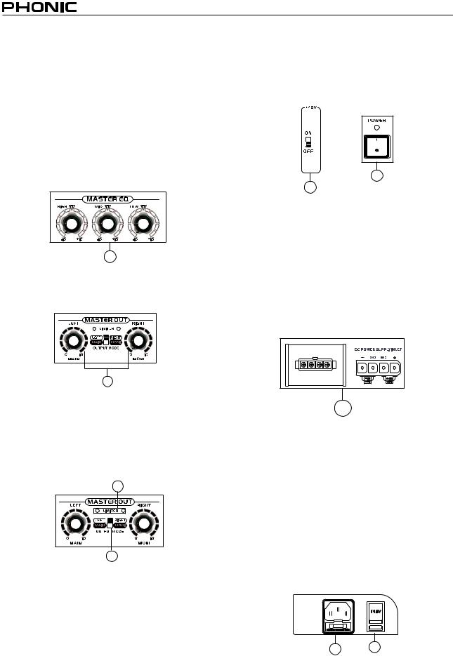
23. System Equalizer
The RoadGear 260 Plus’s built in equalizer provides you with 3 different level controls, for perfect control over the high, mid and low frequencies of your audio. Changing the level of high frequencies included in your audio with enhance the treble sounds, such as guitars, as well as enhancing the crispness of vocals. Changing the level of low frequencies in your audio will enhance bass sounds, including drums and bass guitars, and add to the overall warmth of the sound. Changing middle frequencies can help add crispness to vocals.
The RoadGear 160 Plus features a single bass / treble control for adjusting the high and low frequency balance of your mix.
23 |
24. L/R Level Controls
These controls are used to adjust the final volume level of the MAIN Left and Right signal, sent to the power amplifier and respective outputs (as set by the mode selector switch).
24
25. Limiter Indicators
There are 2 limiters built-in the stereo power amplifier featured in the RoadGear 160 Plus and 260 Plus. The limiters will kick into action (and these LEDs illuminate) when the signal levels become excessive. The limiter system will help prevent any damage from occurring to any of your equipment, as well as try to maintain signal clarity. However, if these LEDs are lighting up, it is advisable to turn the main level controls.
25 |
26 |
26. Mode Selector
Thisisusedtoalternatetheuseofthepoweramplifieroutputs.If stage monitors are used in your set of speakers, then the switch can be set to the MAIN / MONI position. On the RoadGear 260 Plus, this will allow you to plug main speakers into the LEFT / MAIN speaker outputs, and a set of passive monitors (with an impedance of 8Ω or above) to the RIGHT / MONI outputs. On the RoadGear 160 Plus, this selection will cause the left speaker output to send the main signal (in mono); the right speaker output will send the monitor signal. When set to LEFT / RIGHT, the speaker outputs send the main left and right signals as normal.
27. +48V Switch (RoadGear 260 Plus only)
This switch supplies +48V of phantom power to all input channels, used for powering condenser microphones.
28. Power Switch
This button is used to turn the device on and off.
28
27
Rear Panel
29. DC Power Supply Input
This DC power input is used to connect the RoadGear 12VDCto±48VDC converter (12VDC-to±40VDC on RoadGear 160 Plus) (and portable 12V battery) to the RoadGear, enabling you to use the RoadGear system when an AC power source is unavailable. The rightmost socket is used for the positive connection, and the leftmost is used for the negative. The two middle sockets are used for grounding. The power supply used should not exceed 51VDC(44VDC on RoadGear 160 Plus) as to ensure safe operation of the RoadGear.
29 |
30. Power Connector and Fuse Holder
This port is used to plug the female end of the included AC power cable. The other end should be connected to an appropriate power source. Just below this connector is the RoadGear’s fuse holder. In the event that the fuse blows, users can open this holder, remove the old fuse and replace it with another suitable fuse (listed near the power connector).
31. Voltage Selector
The Voltage Select switch is used to adapt the RoadGear to different Countries’ voltage levels. You are able to select between 115V (which you can use in Countries with standard voltage between 100V and 120V) and 230V (which can be used in Countries with standard voltage between 220V and 240V).
30 31
Road Gear 160 Plus/Road Gear 260 Plus
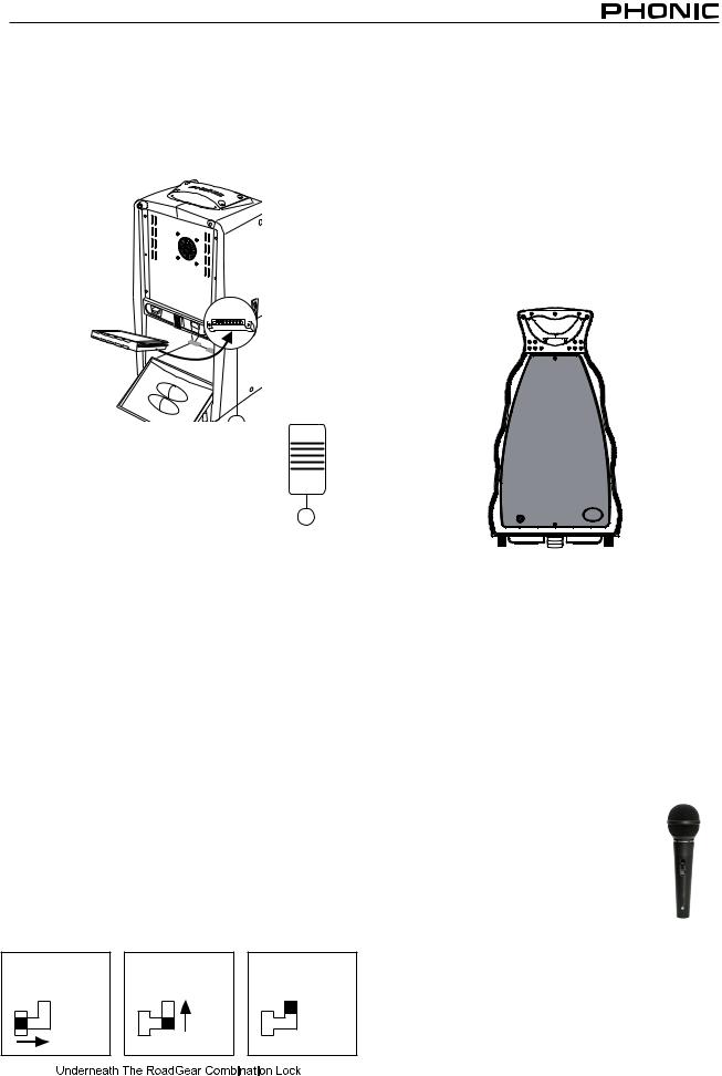
32. Wireless Module Slots
Located conveniently within the RoadGear storage compartment, these two slots accept the UM-R11 wireless receiver module (available with the UM31, UM41 and UM51 wireless microphone kits). The wireless signal received by the left slot is sent to channel 2 of the RoadGear mixer, whereas the right slot is sent to channel 1.
33. Storage Compartment Latch
This small latch keeps the storage compartment closed when not in use. Flick it up before opening, and be sure not to force open the storage com-
partment as to avoid damaging this latch.
33
Combination Docking Lock
The docking locks of the RoadGear are combination locks, which require the user to enter a pre-set combination to open them. Please observe the following instructions to opening the lock.
1)The default code of the lock is 000. Please enter this code the first time you use the RoadGear.
2)To change the lock’s code, first open the latch and find a small lever on the underneath of the lock. Pull it towards the center of the lock, and up, until it sticks into place.
3)Change the number dials to your desired secret code. Ensure you either remember the code or write it down somewhere, as to not have to attempt to break the RoadGear apart in a way that would not be favorable to it whatsoever.
4)After entering your desired code, replace the small lever underneath the lock into its original position and voila! Your new, secret code is set.
This process must be repeated for each lock separately. It’s advised that you have the same code for each lock, as to avoid confusion.
The RoadGear Speakers
The specially molded speakers that are included in both sets provide 8 inch woofers, as well as a 1” compression driver for high quality sound reproduction. Included with the speakers are two 30 foot speaker cables. Each speaker has an impedance of 8Ω.
It is important that users do not pick the RoadGear up by the latches that hold it in place when the kit is assembled. Doing so can cause damage to the latches, making them useless. Furthermore, when using the speakers, be sure to lock the latches at the lower-rear end of the speaker back into place. This also avoids damaging the latch.
Microphone
Included with the RoadGear sets will be a microphone (two with the RoadGear 260 Plus), more specifically the Phonic
UM99 microphone. The Phonic UM99 will no doubt supply you with a fantastically refined sound for use in public addresses or even for vocals in live performances.
Polar Pattern: Cardioid (unidirectional)
Frequency Response: 50 Hz – 15 kHz
Impedance: 600Ω ± 30% (at 1000 Hz)
Sensitivity: -72dB ± 3 dB (SPL = 74 dB, 0 dB = 1V/μ bar; at
1000 Hz indicated by open circuit)
Switch: on & off
Dynamic Microphone Cartridge: CUM-112 (copper voice coil)
Mechanical Spec: Dimensions: Ø52 x 178 mm
Weight: 232g (without cable)
UM99
Road Gear 160 Plus/Road Gear 260 Plus
Optional Accessories
In addition to all this, the RoadGear sets provide you with the option of using various added features. Wireless microphones, with 2 module inputs conveniently placed at the rear of the mixer, are a fantastic way to ensure the microphone cord is never in the way. Dual and single speaker stands compatible with the RoadGear speakers enable you to position your speakers in a way that best suits your setting, for a greater dispersion of audio. These just add to the ease and convenience that RoadGear provides.
The following is a list of all optional accessories:
TB-RG: RoadGear Travel bag, used to protect the RoadGear during transportation or in storage.
MK1-RG: RoadGear Speaker wall mount kit.
MK2-RG: RoadGear Dual Speaker Mount, allow you to mount two RoadGear speakers at one tripod stand.
SK1: Two Speaker Stands, including carry bag.
SK2: Two Mic Stands & two Speaker Stands, including carry bag.
Wireless Microphone
There are 3 different wireless microphone kits available for the RoadGear mobile audio systems: the UM31, UM41 and UM51. Each of these systems provides users with the same wireless receiver, however includes either a handheld, lavaliere or headset microphone.
UM31 Handheld System
●Handheld transmitter (HT-100)
●Wireless receiver module (UM-R11)
UM41 Lavaliere System
●Lavaliere microphone (ML-10)
●Bodypack transmitter (BT-200)
●Wireless receiver module (UM-R11)
UM51 Headset System
●Headset microphone (MH-20)
●Bodypack transmitter (BT-200)
●Wireless receiver module (UM-R11)
RF Frequency |
614 - 870 MHz |
Oscillation Type |
PLL Synthesized Control Oscillation |
Channels |
16 Channels |
Frequency Response |
50Hz - 18KHz, +/-3dB |
Bandwidth |
24MHz |
Operation Range |
100m |
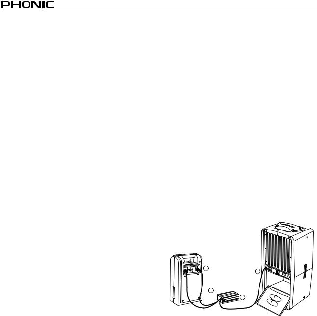
Battery Pack
The BP-RG Battery Pack and CV-RG 12 volt DC-to-DC converter can be used to power the RoadGear in areas where no AC power supply is available. The battery pack should provide up to 4 hours of continuous use, and is rechargeable.
Model Number |
BP-RG Battery pack |
Charge Time |
30 hours |
Battery Time |
4 hours |
Lighting Time |
Up to 25 hours |
Dimensions (W x H x D) |
226x325x99mm 8.9"x12.8"x3.9" |
Weight |
7.75 kg (17.1 lbs) |
|
|
Model Number |
CV-RG DC to DC converter |
Input Voltage |
12V nomi |
Output Voltage |
+48VDC and -48VDC |
Input Fuse |
40 amp |
Output Fuse |
10 amp |
Dimensions (W x H x D) |
100x50x166mm 3.9"x2.0"x6.5" |
Weight |
1.27 kg (2.8 lbs) |
2
3
1 OFF
4 ON
10 |
Road Gear 160 Plus/Road Gear 260 Plus |
 Loading...