


Firefly 808
FIREWIRE INTERFACE
IMPORTANT SAFETY INSTRUCTIONS
The apparatus shall not be exposed to dripping or splashing and that no objects |
|
|
|
with liquids, such as vases, |
|
|
|||
|
|
shall be placed on the apparatus. The MAINS plug is used as the disconnect device, the disconnect device shall remain readily operable.
Warning: the user shall not place this apparatus in the 


 area during the operation so that the mains switch can be easily accessible.
1.Read these instructions before operating this apparatus.
2.Keep these instructions for future reference.
3.Heed all warnings to ensure safe operation.
. Follow all instructions provided in this document.
. Do not use this apparatus near water or in locations where condensation may occur.
6.Clean only with dry cloth. Do not use aerosol or liquid cleaners. Unplug this apparatus before cleaning.
7.Do not block any of the ventilation openings. Install in accordance with the manufacturer’s instructions.
8.Do not install near any heat sources such as radiators, heat registers, stoves, or other apparatus (including 


 .
.
9.Do not defeat the safety purpose of the polarized or grounding-type plug. A polarized plug has two blades with one wider than the other. A grounding type plug has two blades and a third grounding prong. The wide blade or the third prong is provided for your safety. If the provided plug does not  into your outlet, consult an electrician for replacement of the obsolete outlet.
10.Protect the power cord from being walked on or pinched particularly at plug, convenience receptacles, and the point where they exit from the apparatus.
11.Only use attachments/accessories 


 by the manufacturer.
12.Use only with a cart, stand, tripod, bracket, or
table 


 by the manufacturer, or sold with the apparatus. When a cart is used, use caution when moving the cart/apparatus
combination to avoid injury from tipover.
13.Unplug this apparatus during lighting storms or when unused for long periods of time.
1 . Refer all servicing to 


 service personnel. Servicing is required when the apparatus has been damaged in any way, such as power-supply cord or plug is damaged, liquid has been spilled or objects have fallen into the apparatus, the apparatus has been exposed to rain or moisture, does not operate normally, or has been dropped.
CAUTION |
RISK OF ELECTRIC SHOCK |
DO NOT OPEN |
CAUTION: TO REDUCE THE RISK OF ELECTRIC SHOCK, |
DO NOT REMOVE COVER (OR BACK) |
NO USER SERVICEABLE PARTS INSIDE |
REFER SERVICING TO QUALIFIED PERSONNEL |
The lightning flash with arrowhead symbol, within an equilateral triangle, is intended to alert the user to the presence of uninsulated “dangerous voltage” within the product’ 


magnitude to constitute a risk of electric shock to persons.
The exclamation point within an equilateral triangle is intended to alert the user to the presence of important operating and maintenance (servicing) instructions in the literature accompanying the appliance.
WARNING: To reduce the risk of or electric shock, do not expose this apparatus to rain or moisture.
CAUTION: Use of controls or adjustments or performance of procedures other than those 


 may result in hazardous radiation exposure.

FIREFLY 808
FIREWIRE INTERFACE
INTRODUCTION ..................................................................................................................... |
4 |
FEATURES .............................................................................................................................. |
4 |
QUICK START / SET UP........................................................................................................... |
5 |
FRONT PANEL DESCRIPTION ............................................................................................... |
6 |
REAR PANEL DESCRIPTION ................................................................................................ |
7 |
FIREWIRE INTERFACE ......................................................................................................... |
9 |
SYSTEM REQUIREMENTS ........................................................................................ |
9 |
DRIVER INSTALLATION ........................................................................................... |
9 |
CHANNEL ASSIGNMENT ........................................................................................... |
13 |
CUBASE LE ............................................................................................................... |
13 |
FIREWIRE DEVICE CONTROL PANEL................................................................... |
14 |
FIREFLY 808 MIXER SOFTWARE............................................................................. |
16 |
STAND ALONE MODE .......................................................................................................... |
18 |
APPLICATION ........................................................................................................................ |
19 |
DIMENSIONS ........................................................................................................................ |
22 |
SPECIFICATIONS.................................................................................................................. |
23 |
BLOCK DIAGRAM ....................................................................................................................... |
24 |
APPENDIX ...................................................................................................................................... |
25 |
Phonic preserves the right to improve or alter any information within this document without prior notice. V1.0 JUL 18th,2007

INTRODUCTION
Congratulations on your purchase of one of the newest members of the FireWire products family fromPhonic,theFirefly808. Weknowhowtomake the best audio gear for you and we know your need to create great recordings and productions. The
Firefly 808 features a eight mic/line inputs (with
+48V phantom power), digital AES/EBU I/O and word sync, ADAT I/O, MIDI I/O, S/PDIF I/O, and all of these with a FireWire interface for digitally transferring your audio to your computer in high resolution audio (up to 192kHz) that meets today modern productions standards.
We know how eager you are to get started – wanting to get the mixer out and hook it all up is probably your number one priority right now – but before you do, we strongly urge you to take a look through this manual. Inside, you will find important facts and figures on the set up, use and applications of your Firefly 808. If you do happen to be one of the many people who refuse to read user manuals, then we just urge you to at least glance at the Instant Setup section. After glancing at or reading through the manual (we applaud you if you do read the entire manual), please store it in a place that is easy for you to find, because chances are there’s something you missed the first time around.
FEATURES
FireWire (IEEE 1394) audio interface
24-bit resolution, up to 192k Hz sampling rate
18 simultaneous inputs and outputs FireWire audio interface
8 microphone preamps w/ trim control and individual phantom power switches
8 analog line Inputs including 2 Instrument Inputs
8 channels of optical ADAT I/O (4 ch. via 96k dual SMUX)
S/PDIF I/O, AES/EBU I/O, MIDI I/O and word clock I/O
Headphone output and Main output with volume control for monitoring purpose
Channel meters on channel 1 to 8 for input or output
Synchronization, sampling rate, digit I/O and MIDI in/out indicators
Dual FireWire ports for daisy chaining and direct connection to Mac or PC
Stand-alone mixer functionality for field and studio use without computer
Instrument input, pad switch, balanced TRS send jacks on Inputs 1 and 2
Compatible with Windows XP and Mac OSX
Steinberg Cubase LE DAW software included
|
FIREFLY 808 |

Quick Start
1.Connect the Firefly with the supplied FireWire cable to a free port on your computer
2.Connect the supplied AC into the power inlet connector at the rear back of the Firefly 808.
Turn the unit on using the power switch at the front face of the unit.
3.Install all drivers included with your Firefly at your computer and select the Firefly
4.Connect one microphone on the frontal XLR input connector, take a look at the mic LED meter and configure it to a good recording level.
5.Open your audio software and configure it so you can see the Firefly as your input/output device
6.Use your headphones to monitor if your input and output audio on the Firefly.
7.Now you are ready to start designing high resolution audio productions and ready to find out all the advantages of your brand new Firefly.
Setup
1.If you have experience connecting our FireWire products you’ll find this setup familiar and easy.
2.Turn on your computer and be sure to have a FireWire port available.
3.Connect your Firefly to anAC power outlet with the provided AC cable.
4.Connect the supplied FireWire cable to a port on the back of your Firefly, and connect the other end to your computer. You only need to connect a single FireWire cord to your computer – the other port on the Firefly is to allow you to daisy chain the Firefly with other
FireWire-enabled devices.
5.Turn the unit on using the switch located on the back panel.
6.Your computer will automatically recognize the
Firefly, and you will need to install the drivers that were included with your unit (this is for PC users only – Mac users need only make sure the Firefly is set as their preferred audio input/ output device). Follow the onscreen installation instructions for the Firefly 808, and turn the unit off and on when prompted to. After installation is complete, you should be able to view and edit your Firefly’s channel properties in the Firefly Control Panel.
7.Your next and final thing to do would be to activate the Firefly in your DAW software.
Within the “devices”, “tools” or “properties” pull-down menu, you should find an option that allows you to view your inputs. Activate the
Firefly here, and you’ll be good to go!
FIREFLY 808 |
|
Front Panel Description
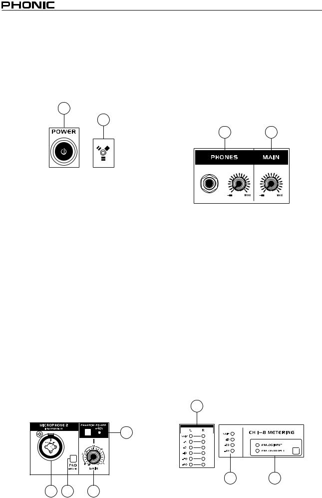
1.Power Button
Push this button in to turn the Firefly 808 on. When the unit is on, the power button will light up.
2.FireWire LED
This LED will light up when a connection to the computer is established through the FireWire interface.
1
2
3.Channel 1 and 2 Inputs
These two combo jacks allow users to connect either balanced XLR 3-pin connectors, for dynamic or condenser microphones, or ¼” TRS phone jacks for instruments such as electric or bass guitars.
NOTE: When plugging line-level signals into the combo jacks, disengage the PAD button to lower the signal level somewhat.
4.Input Gain Controls 1 - 8
Turn these knobs clockwise to increase the microphone/line input gain for the corresponding channels. You have 50dB of gain to work with, but be sure not to adjust it to a level that will make the input meter hit the “clip” point. A good region to be in is about -6dB – this will give you a greater signal level with enough headroom to avoid clipping.
5.PAD selector
This button controls the input sensitivity for channels 1 and 2. Pushing this button in will attenuate the input signal by 20dB, allowing you to connect a microphone or instrument to the combo input jack.
6.+48V Phantom Power
Pushing one of these buttons will activate the +48V phantom power for the corresponding channel, allowing you to use condenser or ribbon microphones (or other devices that require +48V) to work properly. Activation of phantom power will be accompanied by an illuminated LED. If you are not sure if your mic uses phantom power, please refer to the microphone user’s manual.
6
3
7.Headphone Output Jack and Gain Control
AlltheaudiosignalsthataremixedinsidetheFirefly
808 can be monitored with headphones through this jack. You can also use the corresponding control to adjust the signal level.
8.Main Level Control
This control adjusts the final level of the audio sent through the main left and right outputs, the signal of which is taken either from the FireWire return signal or the various analog and digital inputs.
7 8
9.LED Level Meter
This stereo 6-segment LED meter displays the signal level of sum of all 8 analog input channels. User’s are advised to keep this meter sitting around the -6dB mark to make the best use of audio possible without causing any unnecessary clipping.
10. Channel LED Level Meters
The input/output signal levels from analog inputs/ outputs 1 to 8 are shown in these 4-segment LED meters. Whether these meters display the input or output level is dependant on the input/output select button. Users are advised to try and keep their signal level around the -20, -10 marks, as to avoid distortion and clipping.
11. Input/Output Select Switch and Indicator
This button determines whether the LED level meter will display the input or output signal of the Firefly
808’s input/output channels. This button is an easy way to compare input/output levels. Depending which setting is currently active, an LED will light up next to the corresponding setting (“analog input” or “analog output”).
9
10 11
FIREFLY 808
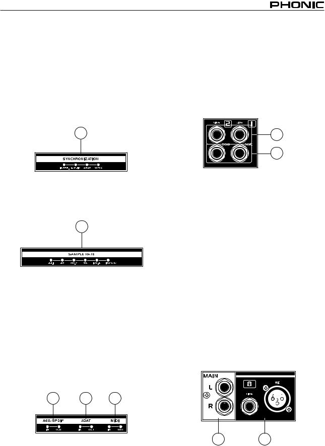
12. Synchronization Indicators
Firefly 808 can be synchronized with any WCLK sync device, enabling you to use it for your audio/ video recording studios as well as cinema and video production that requires high resolution audio.
When the Firefly 808 is synchronized one of these
LEDs will light up to indicate which kind of sync the
Firefly 808 is currently using. If you use the control software to adjust to a device not connected to the
Firefly, the corresponding light will flash briefly and return back to the previous setting.
12
13. Sampling Rate Indicator
When Firefly 808 gets synchronized, one of these
LEDs will light up to show the sampling rate of the device the Firefly is synchronized with, and the Firefly will automatically be set to that rate.
13
14. AES/SPDIF LED Indicator
These input and output LEDs will light up when the AES/EBU or S/PDIF interface is in use.
15. ADAT LED Indicator
You can use your optical devices in conjunction with the Firefly 808. When theADAT optical connection is in use, the input and output LEDs will activate to let you know the connection is successful.
16. MIDI Indicator
When using the MIDI interface, these input and output LEDs will light up.
1 1 16
Rear Panel Description
17. Line Input Channel 1 and 2
These input jacks allow users to connect line-level devices, the signal of which is fed through the FireWire interface, and sent directly out the channel 1 and 2 sends.
18. Channel 1 and 2 Sends
These outputs act as direct sends of the channel 1 and 2 inputs, allowing the signal to be used in other devices.
17
18
19.Input Channels 3 to 8
Each of these channels features a balanced 1/4” TRS Line Inputs and can be used to connect any line level device like CD players, DAT recorders. You can even connect an analog mixer that does not have FireWire interface to allow you to send that signal to the computer. Also present are 3-pin XLR mic input connectors for use with condenser or dynamic microphones.
20. Main Outputs
These 1/4” TRS outputs will allow users to send the main stereo mix of the Firefly 808’s return signal to external devices. The signals from analog channels 1, 3, 5 and 7 are sent to the left output, where the 2, 4, 6 and 8 signals are sent to the right output. When the FireWire interface is in use, users are able to use the Firefly Mixer software's crossfader to select the degree of the FireWire return signal and the analog input signal that is sent to these outputs. The main outputs can be connected to active speakers, monitors, or other mixers, depending on your needs.
20 19
FIREFLY 808
21 |
26 |
2 |
|
|
|
|
|
|
|
|
|
|
|
|
|
|
|
|
|
|
|
|
|
|
|
|
|
|
|
|
|
|
|
|
|
|
|
|
|
|
|
|
|
|
|
|
|
|
|
|
|
|
|
|
|
|
|
|
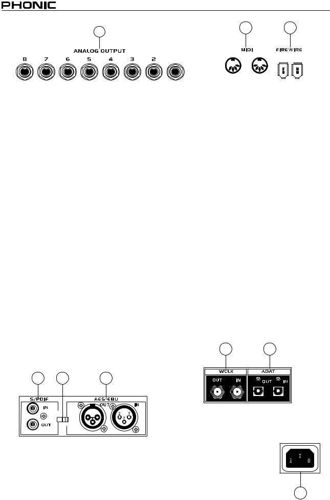
21. Analog Outputs |
25. FireWire Ports |
|
|
|
|
|||
This are balanced 1/4” TRS line outputs with line level signal (+4dBu). Users are able to use these outputs to get a stereo output channel from each pair of odd and even numbered outputs, or even a surround mix (5.2 or 6.2). Analog outputs 1 and 2 can be used to send a stereo mix of your analog inputs or return signal, which is ideal for use with subwoofers (if making a 5.2 or 6.2 system) or just for monitoring the signal.
22. AES/EBU In/Out
This is a standard XLR AES/EBU digital interface that lets you connect your digital AES-enabled devices to your Firefly. The IN or OUT LED on the front of the Firefly will light up when the inputs and outputs are in use.
23. S/PDIF / AES IN Switch
This switch determines which of these digital inputs will be used.
24. S/PDIF In/Out
This is a standard RCA S/PDIF Digital Audio Input/Output that can be used with digital mixers, DAT recorders, or any external device that uses the RCA Digital interface format. Please use a 75 ohms coaxial cable with RCA plug when using S/PDIF. The most common problems or glitches incorporated with S/PDIF transfer are due to use of improper analog cables. Users may also use these inputs for high-speed S/PDIF devices when that option is selected in the computer's Firefly mixer software.
This is a digital FireWire (or PC IEEE 1394) interface that you can use to connect to your computer; use it to send the audio your Firefly receives to your computer, for recording, editing, mixing, and so forth, in your favorite Digital Audio Workstation Software.
You have two FireWire ports at your disposal; however you need only connect one to your computer. The second port will allow you to connect a second Firefly 808, allowing twice the number of inputs!
26. MIDI In/Out
These inputs will allow you to send 16 MIDI channels through the FireWire interface to your computer, as well as receive 16 back. These channels will be present within the Firefly Control Software, and available for use in most MIDI-enabled programs.
27. ADAT In/Out
This is a standard TOSlink ADAT optical interface that you can use in the same way as you would use your typical ADAT devices. This input can also be used for SMUX inputs when this option is selected in the computer's Firefly mixer software.
28. WCLK IN/OUT
These are BNC input/output connectors for standard Word Clock Syncs, as are used in DVTRs and other digital devices.
28 27
2 23 |
22 |
S/PDIF |
IN |
AES IN |
29. AC Power Input and Fuse Holder
Connect the supplied AC power cord to this connector. The other end should be connected to a suitable power supply. The power supply’s fuse is located just below this connector.
If your fuse blows, remove the fuse holder’s cover and replace the fuse with another suitable fuse
(as indicated on the fuse-holder’s
cover).
29
FIREFLY 808
FireWire Interface
System Requirements
The following are the minimum required specifications for use with the Firefly 808. If your computer does not meet these requirements, you will experience lagging of audio and possible freezing of your computer when attempting to operate the mixer.
Windows
•Microsoft® Windows® XP SP1 and SP2 / Vista®
•Available FireWire port (suggested FireWire Interface: ADS Pyro 64 FireWire card with TI chip)
•Intel Pentium® 4 processor or equivalent AMD Athlon processor
•Motherboard with Intel or VIA chipset
•5400 RPM or faster hard disk drive (7200 RPM or faster with 8 MB cache recommended)
•512 MB or more of RAM (1 GB or more recommended)
Macintosh
•OS X 10.3.5 or later with native FireWire support
•G4 or newer processor
•512 MB or more of RAM
Driver Installation
To use the Firefly 808 on a PC, it is important to install all the necessary drivers from the included CD (ASIO and
WDM drivers). It is important that users read all instructions carefully before continuing on to the each step of installation, as users will be required to unplug and plug in their FireWire device. These drivers are not necessary for Mac users.
Windows XP (with Service Pack 1 or 2) / Vista
1.It is recommended that you quit all applications before starting the installation process.
2.Ensure the Firefly is not yet connected to your Computer’s FireWire input.
3.Insert the installation CD included with your Firefly into the CD-ROM drive of your computer. If the CD does not automatically start the installation process within a few moments, then navigate to “My Computer” g your CD-ROM drive g “Drivers and Control Panel” g double-click “setup.exe” to begin the installation manually. The
Phonic FireWire Control Panel software and the Firefly 808 Mixer will also be installed at this time.
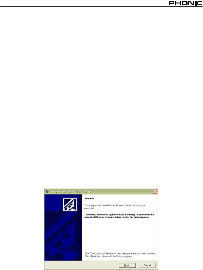
4.Follow the installation instructions.
Make sure no other programs are running on your PC and that the
Firefly 808 is not connected to your PC, then click “Next”.
FIREFLY 808
 Loading...