


FIREFLY 302 USB
Portable USB Audio Interface Interfase de Audio USB Portable
USB
Portable USB Audio Interface


 English / Español / / Português
User's Manual Manual del Usuario
Manual do Usuário

FIREFLY 302 USB
Portable USB Audio Interface Interfase de Audio USB Portable
USB
Portable USB Audio Interface
CONTENTS
INTRODUCTION |
5 |
FEATURES |
5 |
INSTALLATION |
6 |
QUICK START |
6 |
FRONT PANEL DESCRIPTION |
7 |
REAR PANEL DESCRIPTION |
8 |
USB 2.0 INTERFACE |
9 |
DRIVER INSTALLATION |
9 |
CHANNEL ASSIGNMENT |
15 |
OPERATING WITH DAW SOFTWARE |
15 |
PC OPERATION |
16 |
MAC OPERATION |
18 |
SPECIFICATIONS |
21 |
APPLICATION |
75 |
DIMENSION |
77 |
BLOCK DIAGRAM |
78 |
CONTENIDO
INTRODUCCIÓN |
23 |
CARACTERÍSTICAS |
23 |
INSTALACIÓN |
24 |
INICIO RÁPIDO |
24 |
DESCRIPCIÓN DEL PANEL FRONTAL |
25 |
DESCRIPCIÓN DEL PANEL DORSAL |
26 |
INTERFASE USB 2.0 |
28 |
INSTALACIÓN DE DRIVER |
28 |
ASIGNACIÓN DE CANAL |
35 |
OPERACIÓN CON SOFTWARE DAW |
35 |
OPERACIÓN PC |
35 |
OPERACIÓN MAC |
37 |
ESPECIFICACIONES |
40 |
APLICACIONES |
75 |
DIMENSIÓN |
77 |
DIAGRAMA DEL BLOQUE |
78 |

|
CONTEÚDO |
|
42 |
|
42 |
|
42 |
|
42 |
|
43 |
|
44 |
USB2.0 |
45 |
|
45 |
|
51 |
DAW |
51 |
PC |
52 |
Mac |
54 |
|
56 |
|
75 |
|
77 |
|
78 |
INTRODUÇÃO |
58 |
RECURSOS |
58 |
INSTALAÇÃO RÁPIDA |
59 |
INICIO |
59 |
PAINEL FRONTAL |
60 |
PAINEL TRASEIRO |
61 |
USB 2.0 INTERFACE |
62 |
INSTALAÇÃO DE DRIVERS |
62 |
AJUSTE DE CANAIS |
67 |
OPERAÇÃO COM SOFTWARE DAW |
67 |
OPERAÇÃO EM WINDOWS |
69 |
OPERAÇÃO EM MAC |
71 |
ESPECIFICAÇÕES |
74 |
APLICAÇÕES |
75 |
DIMENSÕES |
77 |
DIAGRAMA DE BLOCO |
78 |
Phonic preserves the right to improve or alter any information within this document without prior notice Phonic se reserva el derecho de mejorar o alterar cualquier información provista dentro de este documento sin previo aviso PHONIC
V1.0 11/19/2010

IMPORTANT SAFETY INSTRUCTIONS
The apparatus shall not be exposed to dripping or splashing and that no objects |
|
|
|
with liquids, such as vases, |
|
|
shall be placed on the apparatus. The MAINS plug is used as the disconnect device, the disconnect device shall remain readily operable.
Warning: the user shall not place this apparatus in the 


 area during the operation so that the mains switch can be easily accessible.
1.Read these instructions before operating this apparatus.
2.Keep these instructions for future reference.
3.Heed all warnings to ensure safe operation.
4.Follow all instructions provided in this document.
5.Do not use this apparatus near water or in locations where condensation may occur.
6.Clean only with dry cloth. Do not use aerosol or liquid cleaners. Unplug this apparatus before cleaning.
7.Do not block any of the ventilation openings. Install in accordance with the manufacturer’s instructions.
8.Do not install near any heat sources such as radiators, heat registers, stoves, or other apparatus (including 


 .
.
9.Do not defeat the safety purpose of the polarized or grounding-type plug. A polarized plug has two blades with one wider than the other. A grounding type plug has two blades and a third grounding prong. The wide blade or the third prong is provided for your safety. If
the provided plug does not into your outlet, consult an electrician for replacement of the obsolete outlet.
10.Protect the power cord from being walked on or pinched particularly at plug, convenience receptacles, and the point where they exit from the apparatus.
11.Only use attachments/accessories 


 by the manufacturer.
12.Use only with a cart, stand, tripod, bracket, or
table 


 by the manufacturer, or sold with the apparatus. When a cart is used, use caution when moving the cart/apparatus
combination to avoid injury from tipover.
13.Unplug this apparatus during lighting storms or when unused for long periods of time.
14.Refer all servicing to 


 service personnel. Servicing is required when the apparatus has been damaged in any way, such as power-supply cord or plug is damaged, liquid has been spilled or objects have fallen into the apparatus, the apparatus has been exposed to rain or moisture, does not operate normally, or has been dropped.
CAUTION |
RISK OF ELECTRIC SHOCK |
DO NOT OPEN |
CAUTION: TO REDUCE THE RISK OF ELECTRIC SHOCK, |
DO NOT REMOVE COVER (OR BACK) |
NO USER SERVICEABLE PARTS INSIDE |
REFER SERVICING TO QUALIFIED PERSONNEL |
The lightning flash with arrowhead symbol, within an equilateral triangle, is intended to alert the user to the presence of uninsulated “dangerous voltage” within the product’


magnitude to constitute a risk of electric shock to persons.
The exclamation point within an equilateral triangle is intended to alert the user to the presence of important operating and maintenance (servicing) instructions in the literature accompanying the appliance.
WARNING: To reduce the risk of 
 or electric shock, do not expose this apparatus to rain or moisture.
CAUTION: Use of controls or adjustments or performance of procedures other than those 


 may result in hazardous radiation exposure.

INTRODUCTION
Congratulations on your purchase of one of the newest members of the Phonic Firefly series of recording interfaces, the Firefly 302 USB. Through the Firefly’s ultra low-noise microphone input and two line inputs, together with the USB 2.0 interface, users are able to digitally transfer their audio to a computer in high resolution audio that meets today’s modern production standards (24-bit, with a sampling rate selectable up to 192 kHz). Never again will you have to worry about loss of audio, as the Firefly is the only tool you need to transfer those analog recordings to digital.
Light, easy to use, and with no problematic configuration necessary, the Firefly certainly shines when it comes to simplicity and mobility.
We know how eager you are to get started
– wanting to get the product out of the box and hook it all up is probably your number one priority right now – but before you do, we strongly urge you to take a look through this manual. Inside, you will find important facts on the set up, use and applications of your brand new Firefly. If you do happen to be one of the many people who flatly refuse to read user manuals, then we just urge you to at least glance at the Instant Setup section. After glancing at or reading through the manual (we applaud you if you do read the entire manual), please store it in a place that is easy for you to find, because chances are there’s something you missed the first time around.
FEATURES
●5 x 6 24-bit/192kHz USB stream I/O
●2 x 2 analog operation (RCA)
●Front-panel microphone in (XLR) with
+48V phantom power
●Headphone output with dedicated level control
●Near-zero latency ASIO software direct monitoring
●Power indicator LED
●DC power supply included
●Easy-to-see signal and clip LED indicators for input and output
●Mac OSX and Windows XP / Vista compatible
Firefly 302 USB

INSTALLATION
1.Turn your computer on and connect the
Firefly 302 USB to the computer via the included USB cable. It is recommended not to turn the unit’s power on just yet, however.
2.Run the setup.exe file on the included driver CD, and follow the installation instructions displayed on screen.
3.When prompted to “disconnect and reconnect” the Firefly, change the power select switch on the rear of the device to DC IN.
4.Continue to follow the on-screen installation instructions to finalize the setup.
5.Open your audio editing / DAW software, and check the Firefly’s ASIO driver has been read successfully by the program. This is usually done in the “Devices” submenu. You may also want to edit the Firefly’s properties. This is usually done by clicking on the Tools pull down menu, and selecting “Properties”. In this area, you can usually select the Firefly’s different inputs and outputs, and assign them to various channels. This, of course, depends on the software you are using, so check the software’s user’s manual for more information.
QUICK START
1.Connect the DC converter to the 9-12V jack in and change the power selector switch to the DC IN position.
2.Plug your USB cable into Firefly’s USB port and the other end into any available USB port on your computer. Provided you have already installed the required driver, the computer should detect your Firefly
302 USB.
3.Connect a microphone to the XLR input connector. Talk into the mic and check the LED sig and clip indicators. Adjust the Mic level control as you see necessary.
4.Connect any analog line inputs you wish to use. We advise that you do not attempt to use the 1/4” and RCA connectors on any one input channel at the same time.
5.Open your audio software and configure it so the Firefly 302 USB is set as your input/output device. Please note that the analog and S/PDIF outputs cannot be used to output the signal from the computer simultaneously.
6.Plug your headphones into the headphone output of the Firefly to monitor the return signal.
7.Now you are ready to design high resolution audio productions.
Firefly 302 USB
|
|
|
4 |
|
|
1 |
2 |
3 |
6 |
5 |
7 |
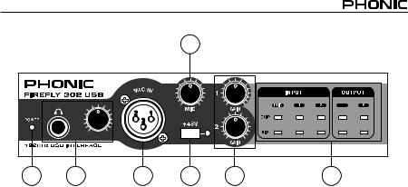
FRONT PANEL DESCRIPTION
1. Power LED Indicator
When you connect the DC power converter and change the power switch to the DC IN position, the unit will be powered and the front power LED will be illuminated.
2. Headphone Output Jack and Control
All the audio signals that are mixed on computer can be monitored with the Headphone output. You can also control the level of this signal with the corresponding level control.
3. XLR Microphone Connector
This is a balanced microphone XLR 3-pin connector, which you can use to connect dynamic or condenser microphones. Phantom power may be applied to allow condenser or ribbon microphones to be connected.
4. Mic Gain
Turn this knob clockwise to increase the Microphone input’s gain. You have 44dB of possible gain with this knob, so please take care when applying gain to ensure the Mic Clip LED does not light up.
5. Gain 1 and 2
These knobs control the input gain for the RCA and 1/4” plug input jacks located on the rear panel. Turn them clockwise to increase the signal level gain or turn them counterclockwise to lower the input levels. Gain 1 controls the Analog In 1 RCA and 1/4” TRS input jacks, and Gain 2 controls the Analog In 2 RCA and 1/4” TRS input jacks. Each gain control is independent of the other, so you can easily match your input levels.
6. +48V Phantom Power
Pushing this button will activate +48V of phantom power on the microphone input, allowing users to connect condenser microphones, ribbon microphones, or other input devices that require +48V power to operate. If you are not entirely sure if your mic requires phantom power, please refer to the microphone’s operation manual or consult the manufacturer.
7. Signal / Clip Indicators
These LED indicators give users an idea of when their analog and mic inputs and outputs are receiving a signal (sig) and when that signal reaches high peaks just prior to the signal being dynamically clipped, which may cause undesirable effects to the integrity of your audio (clip).
Firefly 302 USB
8 |
9 |
10 |
11 |
12 |
|
|
|
|
|
|
|
13 |
14 |
15 |
16 |
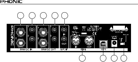
REAR PANEL DESCRIPTION
8. Analog 1/4” TRS Inputs 1 and 2
These are balanced 1/4” TRS Line Inputs and can be used to connect any line level devices, such as CD players or DAT recorders.
9. Analog RCA Inputs 1 and 2
These are RCA inputs and can be used to connect any device like CD players, DAT recorders, turntables, and even analog mixers (taking the signal from a mixer’s Record or 2 track outputs).
Important Note: Keep in mind that the two RCA inputs are completely independent of one another; however these inputs should not be used if the corresponding 1/4” analog 1 and 2 inputs are used, as doing so would have quite undesirable results. You can, however, mix and match these inputs. If, for example, you wanted to use Input 1’s RCA connector and Input 2’s 1/4” connector that would not cause any problems.
10.Analog 1/4” TRS Outputs 1 and 2
This are balanced 1/4” TRS Line Outputs with line level signal (+4dBu). Use them to get a stereo output channel and connect them to active monitors (such as the Phonic P8A), or perhaps to an amplifier and a passive pair of speakers.
You could also use them with signal processors, mixers or other external devices.
11.Analog RCA Outputs 1 and 2
These are RCA line outputs. They accept RCA cables and can be connected to any external device that uses RCA connectors. This could include tape recorders and MP3 recorders.
12.S/PDIF In/Out
These are a standard S/PDIF Digital Audio Input/Outputs that can be use with digital mixers, DAT recorders, or any external device that uses this Digital format. The S/PDIF’s output sampling rate is determined by the sampling rate set by the Firefly control software. Please use a 75 ohm coaxial cable with RCA plug if you are using the S/PDIF connection, as the most common problems associated with glitches in digital interfaces are the result of using poor quality cables.
13.MIDI In/Out
You can have 16 simultaneous MIDI input/output channels sent to and from your computer through the Firefly 302 USB.
14.USB Port
This is a digital USB 2.0 connector that you can use to connect to your computer. Doing so allows users to send their audio signal from the Firefly to the computer, and vise-versa.
15.9-12VDC Input Power Jack
Connect the supplied DC converter to this jack to feed the unit. Please only use this DC converter in order to ensure no damage is done to the Firefly. If for any reason your converter gets lost or damaged and you need a replacement, please contact your local Phonic dealer.
16.Power Switch
Use this switch to turn the Firefly 302 USB on and off.
Firefly 302 USB

USB INTERFACE
SYSTEM REQUIREMENTS
The following are the minimum required specifications for use with the Firefly 302 USB. If your computer does not meet these requirements, you will experience lagging of audio and possible freezing of your computer when attempting to operate the Firefly.
Windows
•Microsoft® Windows® XP (with SP2) or Microsoft® Windows® Vista
•Available USB 2.0 port
•Intel Pentium® 4 processor or equivalent AMD Athlon processor
•Motherboard with Intel or VIA chipset
•5400 RPM or faster hard disk drive (7200 RPM or faster with 8 MB cache recommended)
•256 MB or more of RAM (512 MB recommended)
Macintosh
•OS X Leopard 10.5.1 or later with USB support
•Intel Core 2 Duo or later processor (G4 processors are not supported)
•256 MB or more of RAM (512 MB or more recommended)
DRIVER INSTALLATION
To use the Firefly efficiently (or at all) on any computer, it is important to install all the necessary drivers from the included CD. We advise that users read all instructions carefully before continuing on to each step of the installation process, as they will be asked to, however disconnect and reconnect their Firefly.
Windows XP (with Service Pack 1 or 2)
1.It is recommended that you quit all applications before starting the installation process.
2.Connect the Firefly 302 USB to the computer, leaving the power of the unit off.
3.Insert the installation CD included with your Firefly into the CD-ROM drive of your computer.
If the CD does not automatically start the installation process within a few moments, then navigate to “My Computer” → your CD-ROM drive → “Firefly302USB_Driver” → double-click “setup.exe” to begin the installation manually. The Firefly Control Panel software also will be installed at this time.
4.Follow the on-screen installation instructions, turning the Firefly on when asked to ‘disconnect and reconnect’ the unit.
Firefly 302 USB

Make sure no other programs are running on your PC and click “Next”.
Read and accept the terms of the License Agreement and click “Next” to continue.
10 |
Firefly 302 USB |
Either select a new destination for the installation, or else click “Install” to accept the default directory.
The installation will then commence.
Firefly 302 USB |
11 |
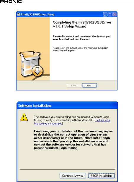
Connect the Firefly 302 USB to the computer and push ‘Finish’to complete the installation.
If a message is displayed indicating that the software has not passed Windows Logo test, click “Continue Anyway.”
After installation is complete, an installation complete message will appear on screen. Click ‘Finish’ to exit.
12 |
Firefly 302 USB |
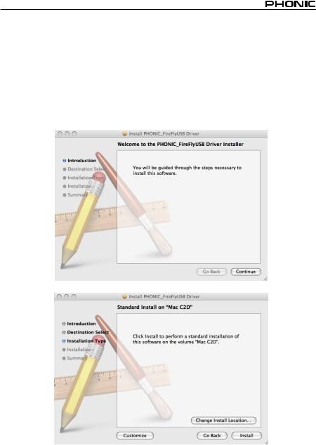
Mac OSX Driver Installation
1.It is recommended that you quit all applications before starting the installation process.
2.Do not connect the Firefly 302 USB to the Mac until after you have installed the driver.
3.Insert the installation disc into the CD drive of your computer. If the CD does not automatically start the installation process, navigate to your CD drive → “Phonic” → “Firefly302USB” → then run “PHONIC_FireflyUSB.mpkg” to begin the installation manually. The Firefly Control Panel software also will be installed at this time.
4.Follow the on-screen installation instructions.
5.After installing the Mac driver, connect the Firefly 302 USB to the Mac’s USB port.
Select “Change Install Location...” to select a new destination for the Mac software. If not, the software will automatically be installed to the default location.
Firefly 302 USB |
13 |
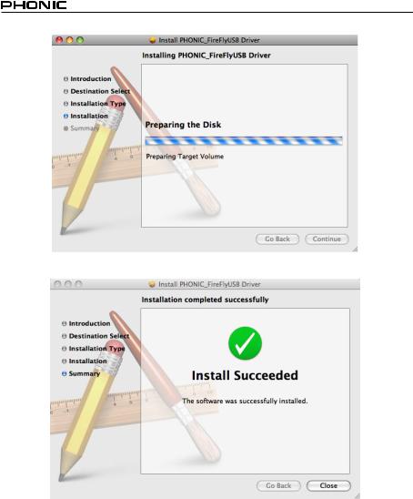
Click ‘Close’ once the installation has completed.
14 |
Firefly 302 USB |

CHANNEL ASSIGNMENT
When using a Digital Audio Workstation on a PC, and within the included Phonic Firefly
302 USB control panel software, the following names have been attributed to the input channels of the Firefly.
Channel Name |
Firefly Channel |
Analog In 1 |
1/4” and RCA Analog Input 1 |
Analog In 2 |
1/4” and RCA Analog Input 2 |
Mic In |
Microphone Input |
Mic In |
Microphone Input |
S/PDIF In |
S/PDIF Input |
S/PDIF In |
S/PDIF Input |
Midi In |
MIDI Input |
If you would like to use the Firefly 302 USB as your default audio output device on your PC, simply go into the Windows control panel and select “Sound and Audio Devices.” Select the Audio tab, and use the pull-down menu to select one of the Firefly 302 USB’s inputs from the list of available output devices. The Firefly 302
USB can also be selected as the default output device for individual programs by editing said programs’ settings / options.
OPERATING WITH DAW SOFTWARE
After successfully completing the installation process, the following process must be followed to work efficiently with the Firefly 302
USB. In the following example, we are using Cubase - however most other software should be similar.
1.Open the program.
2.Go to the ‘Devices’pull-down menu and select ‘Device Setup’. On the left, select ‘VST Multitrack’.
3.From the ASIO Driver drop-down list select the
‘Firefly302USB ASIO Driver’. A pop-up box will ask you if you want to switch to the ASIO driver. Click ‘Switch’.This completes the basic setup.
4.The following steps should be followed to activate audio tracks received from or sent by the
Firefly 302 USB.
a.Go to the “devices” pull-down menu and select ‘VST Inputs’. This will display the various inputs (“Analog In 1”, “Analog In 2”, etc.)
b.Activate channels by clicking the “Active” button located next to each channel name.
5.For further instructions on the operation of Cubase, please consult the owner’s manual by pressing F1 while the program is open.
If you wish to reset the Firefly ASIO driver, simply go to the ‘devices’ pull-down menu and select ‘device setup’. Simply click ‘reset’ and select the ‘Firefly302USBASIODriver’.Click‘ok’tocontinue and the Firefly 302 USB should once again become functional.
Firefly 302 USB |
15 |
WINDOWS OPERATION
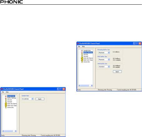
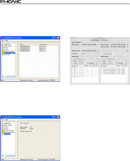
The Firefly control panel on the PC can be accessed at any time by entering choosing the shortcut from your Programs menu. This program will not only allow users to alter their device and channel names and properties, but will also let them adjust buffer settings, change sampling rates, and so forth.
Sample Rate
In this menu, users are able to adjust the sampling rate of the Firefly 302 USB. The sampling rate can be chosen between 44.1, 48, 88.2, 96,
176.4 and 192 kHz. Press ‘apply’ once a new sampling rate is selected.
Buffer Settings
The Buffer Settings menu is used to adjust the Streaming Buffer, as well as the buffer settings when using the ASIO and WDM drivers.
The ‘Streaming Buffer’ can be adjusted between Minimum (1 millisecond), Small (2 milliseconds), Large (4 milliseconds) and Maximum (8 milliseconds). The selection of the Streaming Buffer size will determine the size of the ASIO and WDM buffer sizes, as displayed in the table at the bottom of this page.
When selecting a new buffer size, users can click ‘Apply’ to apply the newly selected buffer setting to the device.
|
|
|
Streaming Buffer Setting |
|
||
|
|
Minimum (1 ms) |
Small (2 ms) |
Large (4 ms) |
Maximum (8 ms) |
|
|
|
|
|
|
|
|
Setting |
Minimum |
1.5 ms |
3.0 ms |
6.0 ms |
12.0 ms |
|
|
66 samples |
132 samples |
256 samples |
529 samples |
||
|
|
|
|
|
||
Small/Smaller |
2.0 ms |
4.0 ms |
8.0 ms |
16.0 ms |
||
Buffer |
||||||
|
88 samples |
176 samples |
353 samples |
706 samples |
||
|
|
|
|
|
||
/ WDM |
Large/Small |
3.0 ms |
6.0 ms |
12.0 ms |
24.0 ms |
|
|
132 samples |
256 samples |
529 samples |
1058 samples |
||
|
|
|
|
|
||
Maximum/Standard |
4.0 ms |
8.0 ms |
16.0 ms |
32.0 ms |
||
ASIO |
||||||
|
176 samples |
353 samples |
706 samples |
529 samples |
||
|
|
|
|
|
||
|
|
|
|
|
|
|
16 |
Firefly 302 USB |
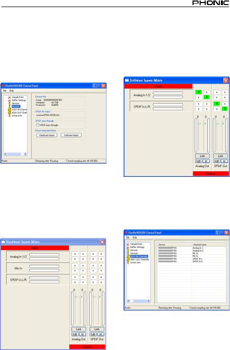
Devices / Device0
In the Devices section, users are able to view and edit the name of any Phonic USB Devices connected to the computer. The Device0 menu offers device info as well as a S/PDIF pass through function for users to take advantage of. There is also two driver-integrated mixers that users are able to utilize to better customize their input/output levels to suit their computer.
Hardware Inputs Mixer
This software-based mixer allows users to adjust levels and routing options of all input signals of the Firefly 302 USB. All of the outputs from this mixer can then be utilized by DAW and other suitable applications.
Level meters are incorporated into the mixing software. Users are given visual depictions of current incoming and outgoing signals from this software mixer.
Software Inputs Mixer
This mixer allows users to monitor and adjust the levels (and routing) of the output signals from the PC. Like the Hardware Inputs Mixer, users are able to adjust volume levels and mute output tracks as necessary. Also like the Hardware mixer, level meters are provided on the software mixer’s inputs and outputs.
Input Channels
The Input Channels section allows users to view and edit the name of the various input channels received from the USB input. Please note that the channel names used in the picture below may differ from your unit’s.
Firefly 302 USB |
17 |
Output Channels
By entering the Output Channels section, users can view and edit the names of the two analog output channels and two S/PDIF output channels that are sent from the computer to the
Firefly.
Driver Information
This section allows users to check the version of their currently used driver and the interface. New drivers will be made available from time to time on the Phonic document center, and an announcement will usually be made on the Phonic home page.
MAC OPERATION
After installing the Firefly 302 USB driver and software to your Mac computer, enter the Audio MIDI Setup application and you should be able to select the Phonic Firefly 302 USB as your default input and output device.
Also in the Audio MIDI Setup, you will be able to adjust volume levels of your various input and output signals, as well as the sampling rate and resolution you want to use. Users are able to select between 44.1, 48, 88.2, 96, 176.4 and 192 kHz sampling rates. Resolution can be selected between 24-bit, 20-bit and 16-bit. Both the sampling rate and resolution can be adjusted in your DAW software as well (depending on what software you use).
Also in the Audio MIDI Setup, tracks can be muted at will, and input signals can be set to
‘thru’, which - put simply - will return the input signals directly back to their corresponding outputs.
The input and output channel names listed correspond with each of the Firefly’s input and outputs. Channels 1 to 6 on the input correspond, in order, with analog inputs 1 and 2 (listed in the Audio MIDI Setup as channels 1 and 2), the microphone input (channels 3 and 4) and the S/PDIF left and right input signals (channels 5 and 6). The output channels 1 to 4 are, in order, analog outputs 1 and 2 and S/PDIF outputs left and right.
18 |
Firefly 302 USB |
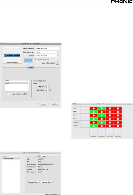
MIDI Setup
Also in the Audio MIDI Setup section, users are able to adjust the Firefly’s MIDI functions by selecting ‘MIDI Devices’ at the top of the window. Within the MIDI Devices section, a ‘Firefly 302
USB’ icon should be present and users can select it to get the following screen.
Firefly 302 USB Control Panel
As many of the Firefly’s features are adjustable through the Audio MIDI Setup section, the Firefly302USB Control Panel serves a few very specific surfaces. As seen in the image below, the main page of the software allows users to view a few important details on the product, including the driver version, serial number, etcetera.
Users can also select one of the two internal mixers that the Firefly’s software offers.
Monitor Mixer
The Monitor Mixer, in essence, allows you to adjust your Firefly’s input signals before sending them off to your DAW software. All of the inputs are listed; the SPDIF 1 and 0 inputs that are listed in the software are representative of the S/PDIF left and right input signals, I2S 3 and 2 are both the microphone input, and the I2S 1 and 0 channels are analog inputs 1 and
2 on the Firefly 302 USB.
You can opt to adjust your device’s input signals in this mixer, or you can just opt to leave it alone all together and rely on your DAW software’s level controls.
In case you’re wondering why there’s only one microphone input, but two microphone channels on the Firefly - this function allows you to make a stereo mix of your microphone signal!
Firefly 302 USB |
19 |
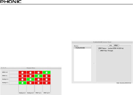
Playback Mixer
The control panel software also offers a Playback Mixer. This is the ‘software mixer’, allowing users to adjust the signal they send out to the Firefly 302 USB’s outputs. All of the output signals from your DAW software can be adjusted individually before being sent out their respective outputs on the Firefly.
As with the Monitor Mixer, each of the listed output channels is representative of one of the
Firefly’s output channels. Channels 1 and 2 are analog outputs 1 and 2, while 3 and 4 are the left and right S/PDIF outputs.
S/PDIF Pass Through
Also included on the Firefly 302 USB Control
Panel is the SPDIF Pass Through function. This basically allows you to send your S/PDIF input signals directly out through from the computer to the Firefly’s S/PDIF outputs.
20 |
Firefly 302 USB |
SPECIFICATIONS
Line Inputs
Connectors |
1/4” TRS, RCA |
|
|
Max input (balanced) |
+10 dBu |
|
|
Max input (unbalanced) |
+10 dBu |
|
|
Input gain range |
-∞ to +10 dBu |
|
|
Impedance |
10K Ohm (Unbalanced), 20K Ohm (Balanced). |
Microphone Input |
|
Connectors |
XLR |
|
|
Available gain |
44dB |
|
|
Input range: |
-40 ~ -+4 dBu |
|
|
Impedance |
2k ohm |
|
|
Line Outputs |
|
Connectors |
1/4” TRS, RCA |
|
|
Max output (balanced) |
+8 dBu |
|
|
Max output (unbalanced) |
+2 dBu |
|
|
Impedance |
100 Ohm (Unbalanced), 200 Ohm (Balanced) |
System |
|
Signal-to-noise ratio |
-97 dB @ 48 kHz (A-WEIGHTING) |
|
|
THD + N |
0.002% 1 kHz, @ 48 kHz |
|
|
Frequency response |
20 Hz to 20 kHz @ 48 kHz,+0.03/-0.23 dB |
|
|
Crosstalk |
-81 dB (A-WEIGHTING) |
|
|
S/PDIF Input and Output |
|
Connector |
Coaxial RCA |
|
|
Sample rates |
44.1, 48, 88.2, 96, 176.4, 192 kHz |
|
|
Headphone Outputs |
|
Max output |
+2 dBV (1.3Vrms) into 32 ohms |
Physical Attributes and Power |
|
Power supply |
DC 9 ~12V (AC to DC adaptor) |
|
|
Dimensions (W x D x H) |
196 x 130 x 44 mm / 7.7” x 5.1” x 1.7” |
|
|
Weight |
0.9 kg / 1.98 lbs |
|
|
Firefly 302 USB |
21 |


INTRODUCCIÓN
Felicitaciones en su compra de uno de los más nuevos miembros de la serie Firefly de Phonic de interfases de grabación, la Firefly
302 USB. A través de la entrada de micrófono con ruido ultra bajo de Firefly y dos entradas de línea, junto con la interfase USB 2.0, los usuarios pueden transferir digitalmente su audio a una computadora en audio de alta resolución que satisface los estándares de producción moderna de hoy (24-bits con un índice de muestreo seleccionable hasta 192 kHz). Usted nunca tendrá que preocuparse más por la pérdida de audio, ya que la Firefly es la única herramienta que usted necesita para transferir aquellas grabaciones análogas a digitales.
Ligera, fácil de utilizar, y sin configuración problemática necesaria, la Firefly brilla ciertamente cuando se habla de la simplicidad y movilidad.
Sabemos cuán impaciente está usted de querer comenzar – deseando sacar el producto de la caja y conectarlo todo es probablemente su prioridad número uno en este momento - pero antes de que usted lo haga, le sugerimos fuertemente que eche una mirada por este manual. Adentro, usted encontrará hechos importantes sobre la configuración, uso y aplicaciones de su nueva Firefly. Si usted es una de la mucha gente que se rechaza plenamente a leer los manuales del usuario, entonces le pedimos que por lo menos eche un vistazo a la sección Instalación. Después de echar un vistazo o de leer el manual (le aplaudimos si usted lee el manual entero), por favor guardelo en un lugar que sea fácil de encontrar para usted, porque puede caber la posibilidad que se le haya escapado algo en la primera leída.
CARACTERÍSTICAS
●5 x 6 E/S de fluido USB a 24-bits/192kHz
●2 x 2 operación análoga (RCA)
●Entrada de micrófono en el panel frontal (XLR) con fuente fantasma de +48V
●Salida de audífono con control de nivel dedicado
●Software ASIO de monitoreo directo con latencia casi-cero
●Indicador LED de energía
●Fuente de alimentación DC incluida
●Indicadores LED de señal y clip fácil de ver para entrada y salida
●Compatible con Mac OSX y Windows XP
/ Vista
Firefly 302 USB |
23 |

INSTALACIÓN
1.Encienda su computadora y conecte la
Firefly 302 USB con la computadora vía el cable USB incluido. Sin embargo, es recomendado no encender la unidad todavía.
2.Corra el archivo setup.exe en el CD de controlador incluido y siga las instrucciones de instalación exhibidas en la pantalla.
3.Cuando le pida que “desconecta y reconecta” la Firefly, cambie el selector de la energía en la parte posterior del dispositivo a DC IN.
4.Continúe siguiendo las instrucciones de instalación en la pantalla para finalizar la configuración.
5.Abra su software DAW / edición de audio, y chequee que el controlador ASIO de Firefly ha sido leído con éxito por el programa. Esto se hace generalmente en el submenú “Devices” (dispositivos). Usted puede también querer editar las propiedades de Firefly. Esto se hace generalmente haciendo click en el menú desplegable de Herramientas, y seleccionando “Propiedades”. En esta área, usted puede seleccionar generalmente las diferentes entradas y salidas de Firefly, y asignalas a varios canales. Esto, por supuesto, depende de software que usted está utilizando, así que chequee el manual del usuario del software para más información.
INICIO RÁPIDO
1.Conecte el convertidor DC a la entrada de jack de 9-12V y cambie el selector de energía a la posición DC IN.
2.Enchufe su cable USB en el puerto
USB de la Firefly y el otro extremo en cualquier puerto USB disponible en su computadora. Siempre que usted ya tiene instalado el controlador requerido, lacomputadoradeberíadetectarsuFirefly
302 USB.
3.Conecte un micrófono a conector de entrada XLR. Hable en el micrófono y chequee los indicadores LED de sig y clip. Ajuste el control de nivel del Micrófono como usted considera necesario.
4.Conecte cualquier entrada de línea análoga que usted desea utilizar. Le aconsejamos que no usar los conectores RCA y 1/4” en canal de entrada a la vez.
5.Abra su software de audio y configuralo de tal manera que la Firefly 302 USB se setea como su dispositivo de entrada/ salida. Por favor observe que las salidas S/PDIF y análogas no pueden ser utilizadas para producir la señal de la computadora simultáneamente.
6.Enchufe sus audífonos en la salida de audífono de Firefly para monitorear la señal de retorno.
7.Usted está listo ahora para diseñar las producciones de audio de alta resolución.
24 |
Firefly 302 USB |
 Loading...