


|
|
|
|
|
|
|
|
|
|
|
|
|
|
|
|
|
|
|
|
|
|
|
|
|
|
|
|
|
|
|
|
|
|
|
|
|
|
|
|
|
|
|
|
|
|
|
|
|
|
|
|
|
|
|
|
|
|
|
|
|
|
|
|
|
|
|
|
|
|
|
|
|
|
|
|
|
|
|
|
|
|
|
|
|
|
|
|
|
|
|
|
|
|
|
|
|
|
|
|
|
|
|
|
|
|
|
|
|
|
|
|
|
|
|
|
|
|
|
|
|
|
|
|
|
|
|
|
|
|
|
|
|
|
|
|
POWERPOD 415RW |
Manual del Usuario |
|||||||||||||||
|
|
|
|
|
|
User's Manual |
||||||||||

Español English
POWERPOD 415RW
POWERED MIXER
MEZCLADORA AMPLIFICADA
ENGLISH..................................................... |
I |
ESPAÑOL.................................................... |
II |
APPENDIX............................................. |
III |
V1.0 08/13/2015

USER'S MANUAL
CONTENTS |
|
INTRODUCTION....................................................................... |
1 |
FEATURES.............................................................................. |
1 |
GETTING STARTED................................................................ |
1 |
CHANNEL STRIP DESCRIPTION............................................ |
1 |
MASTER SECTION DESCRIPTION.................................................. |
1 |
BLUETOOTH SECTION........................................................ |
2 |
USB RECORDER DESCRIPTION................................................ |
2 |
REAR PANEL DESCRIPTION.................................................... |
2 |
USB RECORDER / BLUETOOTH............................................................. |
4 |
SPECIFICATIONS....................................................................... |
5 |
APPENDIX |
|
APPLICATIONS................................................................ |
1 |
DIMENSIONS...................................................................... |
3 |
BLOCK DIAGRAMS.................................................................. |
4 |
Phonic preserves the right to improve or alter any information within this document without prior notice
Español English
English
IMPORTANT SAFETY INSTRUCTIONS
The apparatus shall not be exposed to dripping or splashing and that no objects 

 with liquids, such as vases, shall be placed on the apparatus. The MAINS plug is used as the disconnect device, the disconnect device shall remain readily operable.
Warning: the user shall not place this apparatus in the 


 area during the operation so that the mains switch can be easily accessible.
1. |
Read these instructions before operating this |
|
|
apparatus. |
CAUTION |
2. |
Keep these instructions for future reference. |
RISK OF ELECTRIC SHOCK |
3. |
Heed all warnings to ensure safe operation. |
DO NOT OPEN |
|
||
4. |
Follow all instructions provided in this document. |
CAUTION: TO REDUCE THE RISK OF ELECTRIC SHOCK, |
5. |
Do not use this apparatus near water or in locations |
DO NOT REMOVE COVER (OR BACK) |
NO USER SERVICEABLE PARTS INSIDE |
||
|
where condensation may occur. |
REFER SERVICING TO QUALIFIED PERSONNEL |
6. |
Clean only with dry cloth. Do not use aerosol or liquid |
|
|
cleaners. Unplug this apparatus before cleaning. |
The lightning flash with arrowhead symbol, within an |
||
7. |
Do not block any of the ventilation openings. Install |
equilateral triangle, is intended to alert the user to the |
||
presence of uninsulated “dangerous voltage” within the |
||||
|
in accordance with the manufacturer’s instructions. |
|||
|
product’ |
|
||
8. |
Do not install near any heat sources such as radiators, |
|
||
magnitude to constitute a risk of electric shock to persons. |
||||
|
heat registers, stoves, or other apparatus (including |
|||
|
|
|
||
|
. |
The exclamation point within an equilateral triangle is in- |
||
|
|
|||
9. |
Do not defeat the safety purpose of the polarized or |
tended to alert the user to the presence of important operat- |
||
|
grounding-type plug. A polarized plug has two blades |
ing and maintenance (servicing) instructions in the literature |
||
|
with one wider than the other. A grounding type plug |
accompanying the appliance. |
|
|
|
has two blades and a third grounding prong. The wide |
|
|
|
|
blade or the third prong is provided for your safety. If |
WARNING: To reduce the risk of |
or electric shock, do |
|
|
the provided plug does not into your outlet, consult |
not expose this apparatus to rain or moisture. |
||
|
an electrician for replacement of the obsolete outlet. |
|||
|
|
|
||
10. |
Protect the power cord from being walked on or |
CAUTION: Use of controls or adjustments or performance |
||
|
pinched particularly at plug, convenience receptacles, |
of procedures other than those |
may result in |
|
|
and the point where they exit from the apparatus. |
hazardous radiation exposure. |
|
|
11.Only use attachments/accessories 


 by the manufacturer.
12. Use only with a cart, stand, tripod, bracket, or |
Protective earthing terminal. The apparatus should |
|||
be connected to a mains socket outlet |
with a |
|||
table |
by the manufacturer, or sold with |
|||
protective earthing connection. |
|
|||
the apparatus. When a cart is used, use caution |
|
|||
|
|
|||
when moving the cart/apparatus |
|
|
||
combination to avoid injury from tip- |
WARNING: The terminals marked with symbol of “ |
” may |
||
over. |
|
be of suffcient magnitude to constitute a risk of electric |
||
13. Unplug this apparatus during lighting |
shock. The external wiring connected to the terminals |
|||
storms or when unused for long |
requires installation by a qualifed person or the use of |
|||
periods of time. |
|
ready-made leads or cords. |
|
|
14.Refer all servicing to 


 service personnel. Servicing is required when the apparatus has been damaged in any way, such as power-supply cord or plug is damaged, liquid has been spilled or objects have fallen into the apparatus, the apparatus has been exposed to rain or moisture, does not operate normally, or has been dropped.
2
INTRODUCTION
Congratulations on your purchase of the Phonic Powerpod 415RW Powered Mixer. The Powerpod 415RW is built into a rugged wooden cabinet for heavy-duty use. In order to get the best performance from your Powerpod 415RW, please read all of this safety and operation manual before operating the mixers and keep the manual for future reference.
FEATURES
4 mono input channels for a wide range of Microphone and Line level signals from separate input sockets
Built-in 150 Watt power amplifer
USB recorder and playback device for capturing all performances with ease
Bluetooth connectivity for receiving audio from modern Bluetooth-enabled devices
Class D circuitry on built-in amplifer
Built-in Digital Delay
Super musical 2-band EQ at mono channels
Record out
Tape in with level control
GETTING STARTED
1.Before turning on the power, set the Main output control to the “0” position.
2.Always turn the power off before connecting or disconnecting cables.
3.Cleck the AC Voltage before connecting the AC plug.
4.Do not obstruct the back panel at all for proper ventilation.
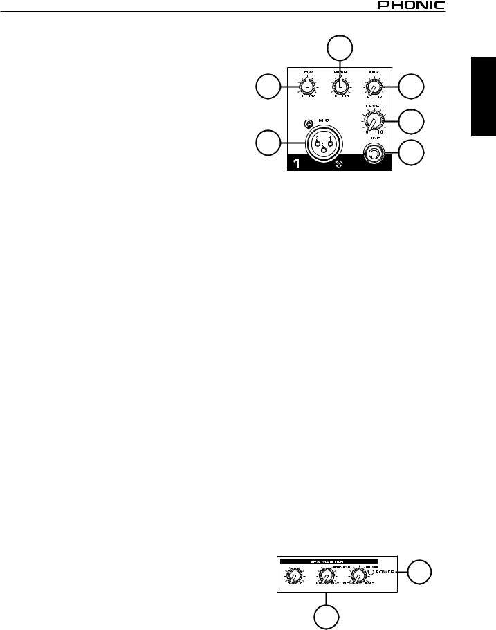
CHANNEL STRIP DESCRIPTION
1. LOW EQ
The control has shelving response giving 15dB of boost or cut at 80Hz. Add warmth to vocals or extra punch to guitars, drums and synths by turning to the right. Turn to the left to reduce stage rumble, hum or to improve a mushy sound.
2. HIGH EQ
Turn to the right to boost high frequencies, adding crispness to percussion from drum machines, cymbals and synths. Turn to the left to cut these frequencies, reducing sibilance or hiss. The control has a shelving response giving 15dB of boost or cut at 12kHz.
3. LEVEL CONTROL
The Level Control determines the proportion of the channel signal in the mix, and provides a clear visual indication of channel level.
|
2 |
|
1 |
5 |
|
4 |
3 |
|
4 |
||
|
4. MIC & LINE INPUT
The MIC input accepts XLR phone jack while the LINE input accepts a 1/4” type phone jack. Please use a low impedance microphone and a properly wired cable for best results. You can only use one of the two connectors at the same time.
5. EFFECT
This knob decides the signal level which will be sent to the built-in digital delay effect control.
MASTER SECTION DESCRIPTION
6. DIGITAL DELAY
The signal from the input channels, processed by the built-in digital delay will feed to the master output. There are three knobs here to control the effect of digital delay.
TIME - This knob adjusts the internal time of the delays; turn to the right to increase the interval time between two delays.
REPEAT - To increase the rate of the delays, turn this knob to the right. You will hear the signal repeat at a faster rate.
LEVEL - The control on the left will adjust the fnal output level of the digital delay.
7. POWER INDICATOR
This LED indicator will light up when the Powerpod 415RW is turned on and active.
7
6
English
POWERPOD 415RW |
1 |
English
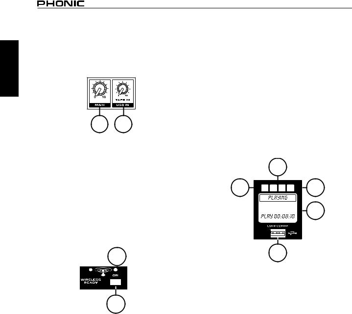
8. USB IN CONTROL
This knob adjusts the USB Playback level as sent to the main mix.
9. MASTER CONTROL
This adjusts the fnal level of the Main bus. It controls the Main bus signal which is output to the speakers.
9 |
8 |
BLUETOOTH SECTION
10. BLUETOOTH ON BUTTON AND INDICATORS
This button turns the Bluetooth function of the Powerpod 415RW on and off. The LEDs that accompany it indicate the status of the feature. The LED immediately above the button shows the feature is turned on while the "WIRELESS READY" LED will light up when a connection is established between a SmartDevice and the Powerpod.
11. BLUETOOTH LEVEL CONTROL
This rotary control will adjust the level of the incoming Bluetooth signal that will be sent to the main mix.
 11
11
10
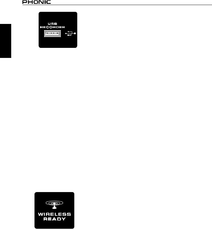
USB RECORDER DESCRIPTION
The USB Recorder’s source signal is taken directly from each individual input channel. While the recordings are indeed in stereo, they are also limited by the Powerpod 415RW’s circuitry, which is mono rather than stereo. When playing back a signal, the signal will pass through the USB In control and then is sent directly to the main mix. Playback of WMA and MP3 with bit rates of up to 320 kbit/s is possible.
12. DISPLAY
This display will display the track number currently being played. It also offers play, pause and record indicators as well as the current play/record time.
13. USB PORT
Connect your USB fash drive to this input. Once a drive is connected, the fles will initiate and the main menu will appear on screen. Users are advised to format their USB memory sticks with the FAT-32 fle system.
14. PLAY BUTTON
Push this button to start and stop playback and recording of the currently displayed track. Starting a track after it is paused will resume the track from the point at which it was paused (in both record and playback mode). When in recording mode, push and hold this button to fnalize recordings.
15. BACK/NEXT BUTTONS
Pushing these buttons will allow users to skip back and forwards between tracks. When the menu is activated, these buttons are used to scroll through on screen options.
16. STOP/MENU BUTTON
Push this button to stop playback or recording when applicable. Push and hold the button to access the USB recorder/player’s main menu.
15
14 


 16
16 
 12
12
13
REAR PANEL DESCRIPTION
17. TAPE IN AND REC OUT
The TAPE IN sockets allow cassette recorders or CD players to be added to the Main output. The RECORD OUTPUT, with RCA phono sockets, provides signal output to a cassette deck and home audio equipment. The nominal output level and impedance are -10dBV/600ohms.
18. POWER CABLE
The Powerpod 415RW features a built-in power cable that can be connected to an appropriate AC power outlet. Ensure the local power levels match those required by your powered mixer. The unit’s required voltage is indicated immediately beside the power cable.
19. POWER SWITCH
This switches the powered mixer on and off. While turn it on, the power on blue LED indicator will light up on the master section of front panel.
2 |
POWERPOD 415RW |

20. SPEAKER OUTPUT JACKS
Speakers can be connected to these sockets, two speakers can be connected to the powered mixer. When using 2 speakers at the same time, use 8~16 ohms speakers. When using one speaker only, use a 4~8 ohms speaker. The total minimum required load is 4 ohms. If the total load is less than 4 ohms, it may damage this powered mixer.
21. MAIN OUT / AMP IN
This unbalanced insert point is a break between the main out and built-in amplifer to allow the main output to be sent to an external signal processor or power amplifer. The insert is a 1/4’ phone jack socket which is normally bypassed. When a jack is inserted, the signal path is broken.
The main output signal appears on the TIP of the plug and the external signal is returned on the RING. A “Y” cable may be required to connect to equipment with separate send and return jacks as shown below:
English
19 |
20 |
21 |
|
MIN. REQUIRED LOAD |
|
|
4 Ohms=SPEAKER A+B |
|
|
MAX OUTPUT=100W/4 Ohms |
|
18 |
|
17 |
POWERPOD 415RW |
3 |
English
“R”Recording
The Powerpod 415RW includes a fexible USB recorder that includes a USB port accompanied by a LCD and four function buttons. Please see the operating instructions below:
Playback: The USB player supports WMA and MP3 playback through USB
1.Power on the device.
2.Insert an appropriately formatted (FAT32) USB fash drive.
3.On the main menu, select “Playback” and press the PLAY button.
4.Press the PLAY button to play the current track, or the << and >>buttons to skip forward and backwards between tracks.
5.Press the MENU button while in the Playback mode to access the File Browser, Delete File, Repeat Mode and Volume Control functions.
6.Press and hold the MENU button for three seconds to exit playback mode and return to the main menu.
Folders - Freely navigate songs in each folder on USB fash disc using the << and >> buttons. Press PLAY button to select, press MENU button to go back.
Repeat Mode - There 4 repeat modes available.
No Repeat - Play each fle in the current folder or root for once.
Repeat one - Constantly repeat selected song.
Repeat Folder - Constantly repeat all the song in the certain folder or root.
Random – Enables random playback of fles in current folder or root.
Record: Users can record high defnition WAV format
1.Power on the device.
2.Insert an appropriately formatted (FAT32) USB fash drive.
3.In the main menu, select “Record” and press the PLAY button to enter recording mode.
4.Select between the 128 kbit/s and 192 kbit/s WAV recording modes and press the PLAY button.
5.Record mode will begin in standby/pause. Push the Play/ Pause button to begin recording. The unit will save the recorded fle into the RECORD directory on the USB device.
6.Push the Play/Pause button to pause recording. Pushing the Play/Pause button again will resume recording from the position at which it was paused.
7.Press the MENU button at any time to save the recording. Once the recording is saved, the system will automatically skip to the next track.
8.To exit out of record mode and return to the main menu, press and hold MENU button for three seconds.
NOTE:
1.The USB rotary control will adjust the playback level only and will not affect recording levels. The only level controls that will affect the recording level are those found on the individual input channels.
2.Users may experience very short instances of drop outs during playback of recorded WAV fles.
“W”Wireless Bluetooth
Operation:
1.Activate Bluetooth by pushing the Bluetooth button.
2.Search for and pair with “Phonic.BT” in the Bluetooth setup menu of your cell phone, tablet, PC, or other Bluetooth-en- abled device.
3.If your device asks for a password, please enter “0000”.
4.Audio signals received through the Bluetooth interface are controlled via the Bluetooth rotary control.
5.If you cannot connect to the Phonic’s Bluetooth input, it might be because it is already connected to another device or someone has erroneously connected to it. Please restart your Phonic product and attempt the Bluetooth connection again.
6.When using smartphones and tablets, it may be an idea to turn “Airplane Mode” or “Flight Mode” on to stop phone calls or push notifcations from interrupting your audio.
NOTE: Not all modern Bluetooth-enabled devices allow for use of external audio playback. In the case of laptops in particular, Bluetooth may be used for data transmission only - depending on the model. This is a limitation of these devices and you will not be able to use the Powerpod ‘RW’ Bluetooth function with these devices.
4 |
POWERPOD 415RW |
 Loading...