


POWERPOD 1062+
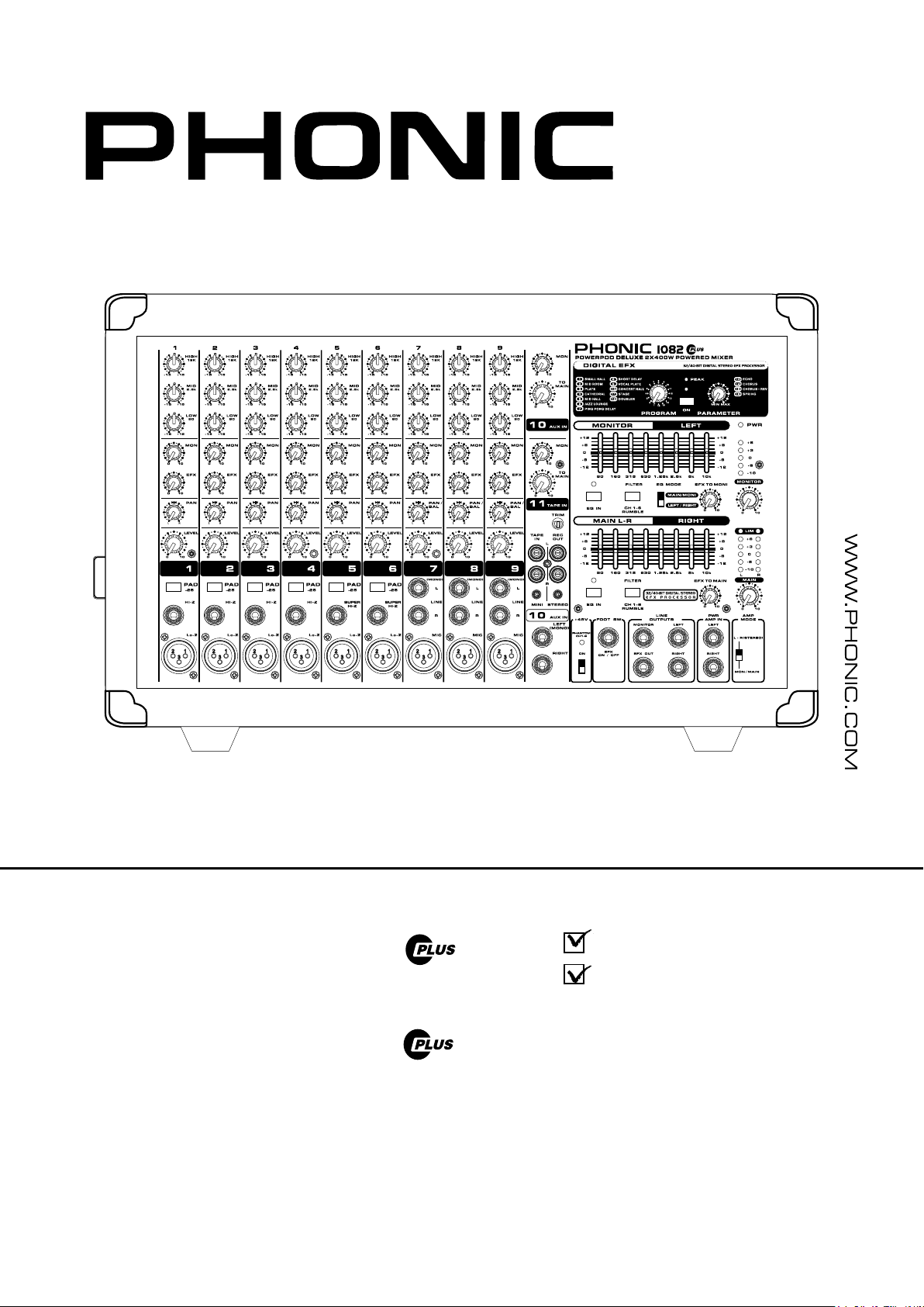
Powerpod 1082 Plus
User's Manual
Manual del Usuario
POWERPOD 1062
POWERPOD 1062R
POWERPOD 1082
POWERPOD 1082R

POWERED MIXERS
MEZCLADORAS AMPLIFICADAS
ENGLISH .....................................I
ESPAÑOL .....................................II
V1.2 10/24/2012
English Español
POWERPOD 1062
POWERPOD 1062R
POWERPOD 1082
POWERPOD 1082R

1
POWERPOD 1062 PLUS / 1062R / 1062FR / 1082 PLUS / 1082R
English
INTRODUCTION......................................................................1
FEATURES...............................................................................1
BASIC SETUP...........................................................................2
MAKING CONNECTIONS....................................................2
CONTROLS AND SETTINGS...................................................3
SPECIFICATIONS...................................................................7
APPENDIX
DIGITAL EFFECTS TABLE.......................................................1
APPLICATIONS.........................................................................2
DIMENSIONS............................................................................4
BLOCK DIAGRAMS..................................................................5
CONTENTS
USER'S MANUAL
Phonic preserves the right to improve or alter any information within this
document without prior notice.
2
POWERPOD 1062 PLUS / 1062R / 1062FR / 1082 PLUS / 1082R
English
1. Read these instructions before operating this
apparatus.
2. Keep these instructions for future reference.
3. Heed all warnings to ensure safe operation.
4. Follow all instructions provided in this document.
5. Do not use this apparatus near water or in locations
where condensation may occur.
6. Clean only with dry cloth. Do not use aerosol or liquid
cleaners. Unplug this apparatus before cleaning.
7. Do not block any of the ventilation openings. Install
in accordance with the manufacturer
’
s instructions.
8. Do not install near any heat sources such as radiators,
heat registers, stoves, or other apparatus (including
.
9. Do not defeat the safety purpose of the polarized or
grounding-type plug. A polarized plug has two blades
with one wider than the other. A grounding type plug
has two blades and a third grounding prong. The wide
blade or the third prong is provided for your safety. If
the provided plug does not
into your outlet, consult
an electrician for replacement of the obsolete outlet.
10. Protect the power cord from being walked on or
pinched particularly at plug, convenience receptacles,
and the point where they exit from the apparatus.
11. Only use attachments/accessories
by the
manufacturer.
12. Use only with a cart, stand, tripod, bracket, or
table
by the manufacturer, or sold with
the apparatus. When a cart is used, use caution
when moving the cart/apparatus
combination to avoid injury from tip-
over.
13. Unplug this apparatus during lighting
storms or wh en unused for long
periods of time.
14. Refer all servicing to
service personnel.
Servicing is required when the apparatus has been
damaged in any way, such as power-supply cord or
plug is damaged, liquid has been spilled or objects
have fallen into the apparatus, the apparatus has
been exposed to rain or moisture, does not operate
normally, or has been dropped.
IMPORTANT SAFETY INSTRUCTIONS
CAUTION: TO REDUCE THE RISK OF ELECTRIC SHOCK,
DO NOT REMOVE COVER (OR BACK)
NO USER SERVICEABLE PARTS INSIDE
REFER SERVICING TO QUALIFIED PERSONNEL
The lightning flash with arrowhead symbol, within an
equilateral triangle, is intended to alert the user to the
presence of uninsulated
“
dangerous voltage
”
within the
product
’
magnitude to constitute a risk of electric shock to persons.
The exclamation point within an equilateral triangle is in-
tended to alert the user to the presence of important operat-
ing and maintenance (servicing) instructions in the literature
accompanying the appliance.
WARNING: To reduce the risk of or electric shock, do
not expose this apparatus to rain or moisture.
CAUTION: Use of controls or adjustments or performance
of procedures other than those
may result in
hazardous radiation exposure.
The apparatus shall not be exposed to dripping or splashing and that no objects
with liquids, such as vases,
shall be placed on the apparatus. The MAINS plug is used as the disconnect device, the disconnect device shall
remain readily operable.
Warning: the user shall not place this apparatus in the
area during the operation so that the mains switch
can be easily accessible.
CAUTION
RISK OF ELECTRIC SHOCK
DO NOT OPEN

1
POWERPOD 1062 PLUS / 1062R / 1062FR / 1082 PLUS / 1082R
English
INTRODUCTION
Phonic would like to congratulate you on the purchase of one of
their extraordinary Powerpod mixers, powered mixers that provide
more than the average. Since its introduction, the entire Powerpod
series has given other powered mixer lines a run for their money.
With fantastically low noise levels, high signal handling abilities,
exceptional output levels, simplied signal routing abilities, and
ultra-smooth controls, the Powerpod 1062 and 1082 models all
provide a level of dependability not often found in powered mixers
as of late.
We know how eager you are to get started – getting the mixer out
and hooking all your gear up is probably your number one priority
right now – but before you do, we strongly urge you to take a look
through this manual. Inside, you will nd important facts and gures
on the set up, use and applications of your brand new mixer. If
you do happen to be one of the many people who atly refuse
to read user manuals, then we just urge you to at least glance at
the Instant Setup section. After glancing at or reading through the
manual (we applaud you if you do read the entire manual), please
store it in a place that is easy for you to nd, because chances are
there’s something you missed the rst time around.
FEATURES
● Powerpod 1062 Plus/R: 600W + 600W / 4 ohm amplier for
main L & R or main / monitor
● Powerpod 1082 Plus/R: 800W + 800W / 4 ohm amplier for
main L & R or main / monitor
● 32-bit digital stereo multi-effect processor with 16 programs
plus one main parameter control, tap control and foot switch
● Dual 10-band graphic equalizers with In / Out switches for main
(stereo)/monitor or main L/R
● 9 balanced mic inputs through XLR jacks
● 12 line inputs through 1/4" jacks
● 2 Super Hi-Z inputs optimized for direct input of acoustic electric
guitars and electric guitars or basses
● 2 built-in limiters
● Rumbling lters for mic inputs
● 3-band channel EQ
● Pad control on channel 1~6
● Monitor and effect sends on each input channel
● Stereo aux input
● +48V phantom power on channels 1 through 6
● Record output with trim control for recording level matching
● Mains power switchable between 115VAC and 230VAC
BASIC SETUP
Getting Started
1. Turn all power off on the Powerpod mixer. To ensure this, the
AC cable should not be connected to the unit.
2. All faders and level controls should be set at the lowest level
to ensure no sound is inadvertently sent through the outputs
when the device is switched on. All levels should be altered to
acceptable degrees after the device is turned on.
3. Plug all necessary instruments and equipment into the device's
various inputs as required. This may include line signal devices,
as well as microphones and/or guitars, keyboards, etc.
4. Plug any necessary equipment into the device's various outputs.
This could include speakers, monitors, signal processors, and/
or recording devices.
NB. No devices other than speakers should be connected to the power amp
outputs. Plugging inappropriate devices into the mixer will likely cause
damage to the device. Also, guitar cables should not be used to connect
ampliers to speakers.
5. Plug the supplied AC cable into the AC inlet on the back of the
device, ensuring local voltage level is identical to that selected
by the Voltage Selector on the rear of your device.
6. Plug the supplied AC cable into a power outlet of a suitable
voltage.
7. Turn the power switch on.
Channel Setup
1. To ensure the correct audio levels of each input channel is
selected, every channel faders should rst be set to 0.
2. Choose the channel that you wish to set the level of, and ensure
that channel has a signal sent to it similar to the signal that will
be sent when in common use. For example, if the channel is
using a microphone, then you should speak or sing at the same
level the performer normally would during a performance. If a
guitar is plugged into that channel, then the guitar should also
be used as it normally would be.
NB. It is probably best to have nothing plugged into channels which are
not being set, just to ensure no signal is inadvertently sent through the
channel.
3. This channel is now ready to be used; you can stop making the
audio signal.
4. You should now select the next channel to set and go back to
follow steps 1 through 3.
Powerpod ‘R’ Models Add:
● USB recorder and playback device for capturing all performances with ease
2
POWERPOD 1062 PLUS / 1062R / 1062FR / 1082 PLUS / 1082R
English
MAKING CONNECTIONS
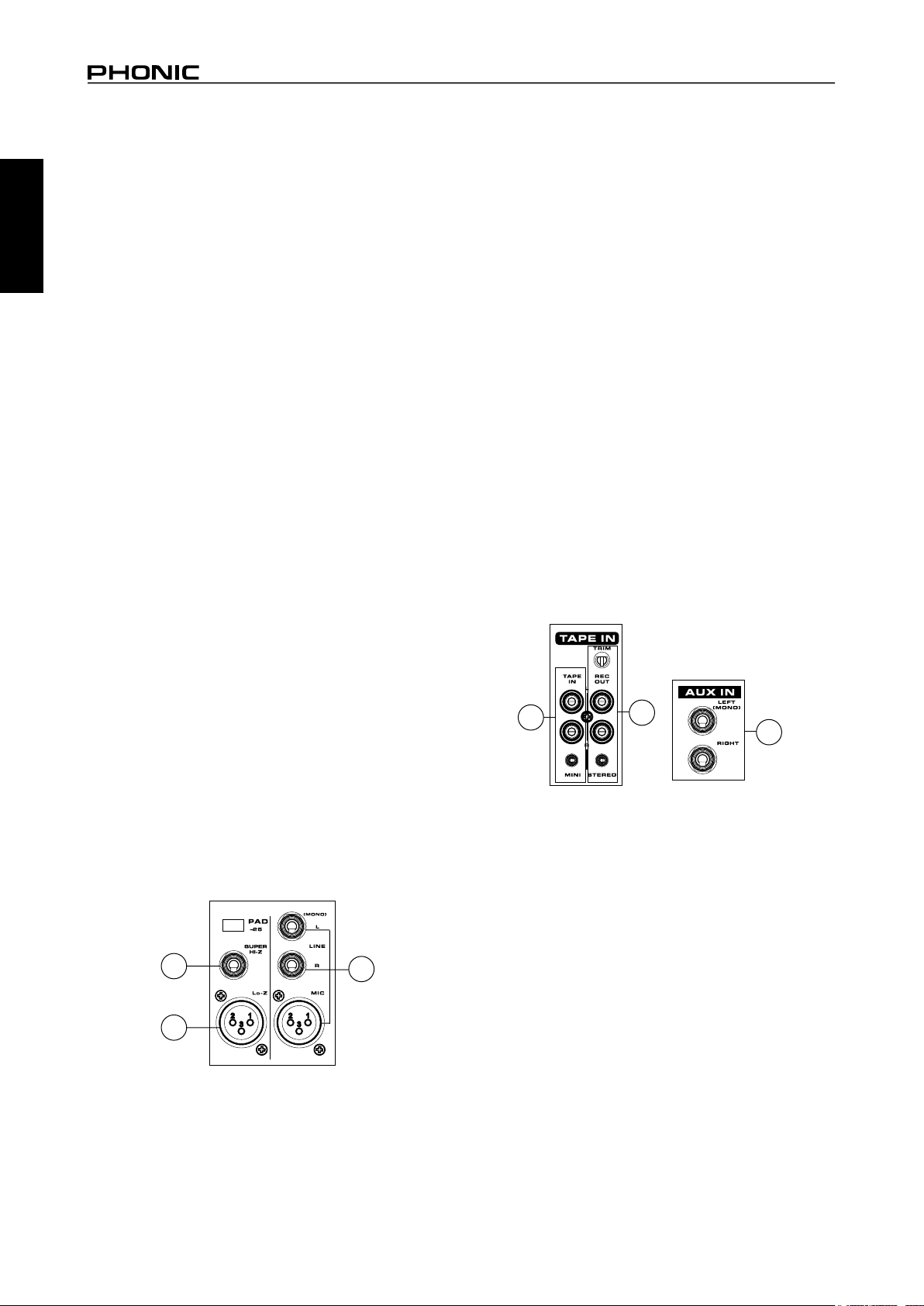
Channel Inputs
The Powerpod 1062 and 1082 models all feature a total on 10 input
channels, including 3 that feature stereo inputs. Each channel
features a microphone XLR jack and at least one 1/4” Phone Jack
for balanced and unbalanced connections. Each stereo channel
features different inputs jacks, accepting either microphone inputs
or stereo line inputs.
1. XLR Lo-Z Inputs
These XLR microphone inputs can be used in conjunction with
a wide range of microphones, such as professional condenser,
dynamic or ribbon microphones, with standard XLR male
connectors. With low noise preampliers, these inputs serve for
crystal clear sound replication.
NOTE: When using an unbalanced microphone, please ensure phantom
power is switched off. However, when using condenser microphones the
phantom power should be activated.
2. 1/4" Hi-Z and Super Hi-Z Input Jacks
These inputs accept typical 1/4” TRS or TS unbalanced inputs. The
Hi-Z inputs accept balanced TRS inputs, and are for Microphone
to line-level device (such as synthesizers and drum machines),
where the Super Hi-Z inputs accept TS unbalanced sources, and
can be used in conjunction with devices with higher impedance
levels (including electric guitars and basses).
NB.When using a line-level device on your mixer, the PAD -25 button should
be initiated.
3. Stereo Channel Inputs
Each of the Powerpod 1062 and 1082 model powered mixers
provide 3 stereo input channels, the inputs of which differ slightly
to the mono channels. The 3-pin XLR inputs featured are for the
addition of microphones with typical XLR male inputs, where the 2
Line 1/4" TS jacks are for the addition of various stereo line level
input devices, such as keyboards. If you wish to use a monaural
device on a stereo return input, simply plug the device’s 1/4" phone
jack into the left (mono) stereo input and leave the right input bare.
The signal will be duplicated to the right due to the miracle of jack
normalizing.
Master Section
4. Tape In (L and R)
The rst of these inputs accommodates RCA cables from such
devices as tape and CD players. In addition to these inputs,
however, Phonic has incorporated a mini stereo jack for the
inclusion of such devices as mini disc (MD), portable CD, and MP3
players (such as the Apple iPod), as well as laptop computers. The
line from this feed is directed to the Tape In mixing bus, before
being fed through to the Main L/R mixing bus.
5. Record Outputs (L and R)
As with the Tape In ports, these outputs will accommodate RCA
cables, able to be fed to a variety of recording devices. Also, similar
to the Tape In ports, included are mini stereo jacks for the addition
of recording devices such as MD players and laptop computers.
A trim control is featured on these outputs to accommodate for
devices with different recording levels.
6. AUX Inputs
These TS inputs connect the mixer with parallel external devices,
such as sub mixers or external effect processors, receiving the
processed signal from another source and feeding it to the AUX
mixing buses. The stereo AUX inputs can be used as monaural
inputs by simply plugging the device’s 1/4" phone jack into the
left (mono) stereo input and leave the right input bare. Your good
friend, Jack Normalizing, will take care of the rest.
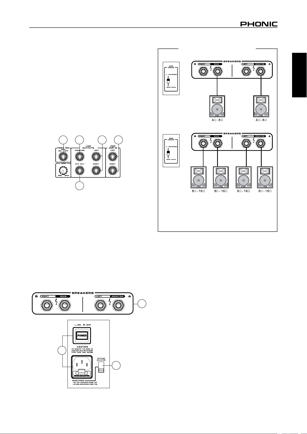
7. Foot Switch Jack
This port is for the inclusion of a non-latching foot switch, used to
remotely adjust properties of the built-in Digital Effect processor.
The Powerpods 1062 and 1082 models all feature a single foot
switch jack, which allows the user to remotely turn on and off the
digital effects.
8. EFX (Effect) Outputs
These 1/4" TS outputs are the nal output from the EFX send
mixing bus. This feed may be used to connect to an external digital
effect processor, or even to an amplier and speakers, depending
on your desired settings.
9. Monitor Outputs
These 1/4" TS outputs are the nal output from the Monitor send
mixing bus. This feed may be used to connect to an amplier and
speaker. Feeding the output from the Monitor out to an amplier
(and possibly an equalizer) and then to a oor monitor speaker
allows artists to monitor their own instruments or vocals whilst
performing, or an engineer to monitor the mix.
2
1
3
4
5
6
3
POWERPOD 1062 PLUS / 1062R / 1062FR / 1082 PLUS / 1082R
English
10. Main Outputs
These jacks will output the nal stereo line level signal sent from
the main mixing bus. The primary purpose of these jacks is to send
the Main output to external devices that may run in parallel with
the mixer. This may include additional power ampliers, mixers,
PA systems, as well as a wide range of other possible signal
processors.
11. Power Amp Inputs
These inputs support 1/4" TS plugs and can be used for the
inclusion of an external line level stereo signals to the built-in
power amplier. If a device is connected to the power amp inputs,
the main feed will automatically bypass the power amp and the
inserted feed will be amplied and sent to the Speaker Outputs
instead.
Rear Panel
12. Speaker Outputs
These jacks are used to connect to speakers, fed from the internal
power amp. On all models, they consist of 1/4" Phone Jacks. The
Amp Select switch determines the operation of these jacks. If the
Amp Select switch is set to "Main L-R (Stereo)" or "Main / Moni" a
single speaker with a 4 to 8 ohm load can be connected to jack A
on both the left and right Speaker Outputs. You can also connect
two speakers with impedances between 8 and 16 ohms to both
jacks A and B of the left and right Speaker Outputs.
NB. Due to the fact that the signal has been processed by the power amp,
these ports should be used in conjunction with passive speakers only to
avoid damaging any other equipment.
SPEAKER SETUP
Using speakers with an incorrect loading can not only cause
distortion, but also irreversible damage to the powered mixer.
Please ensure the loadings of your speakers are consistent
with those shown above.
7
9 10
11
8
12
CONTROLS AND SETTINGS
Rear Panel
13. Power Button and AC Connector
The power button, located on the rear of the mixer, is used to
activate the mixer. Of course, there’s no point in activating the
mixer if there’s no power, therefore an AC connector has been
included to ensure your Mixer gets the power it needs. Please use
the power cable that is included with this mixer only.
NB. Before connecting the AC cable to the Powerpod Mixer, please ensure
the local voltage levels are identical to those chosen by the Voltage Selector
switch.
14. Voltage Selector
This switch allows you to select from 2 mains power modes, 115
VAC / 60 Hz (Allowing you to use the device in Countries with
voltages between 100V and 120V) or 230 VAC / 50 Hz (Allowing
you to use the device in Countries with voltages between 220V and
240V). To change the Voltage Selector, you must rst unscrew and
remove the plastic cover that protects the switch. After changing
the Voltage, please replace the plastic cover to ensure the voltage
level is not inadvertently altered.
NB. Using incorrect voltages can cause irreversible damage to the mixer.
All care must be taken in selecting the voltage appropriate to your zone. If
unsure of local voltage levels, contact a knowledgeable source before using
this mixer.
14
13
4
POWERPOD 1062 PLUS / 1062R / 1062FR / 1082 PLUS / 1082R
English
Channel Controls
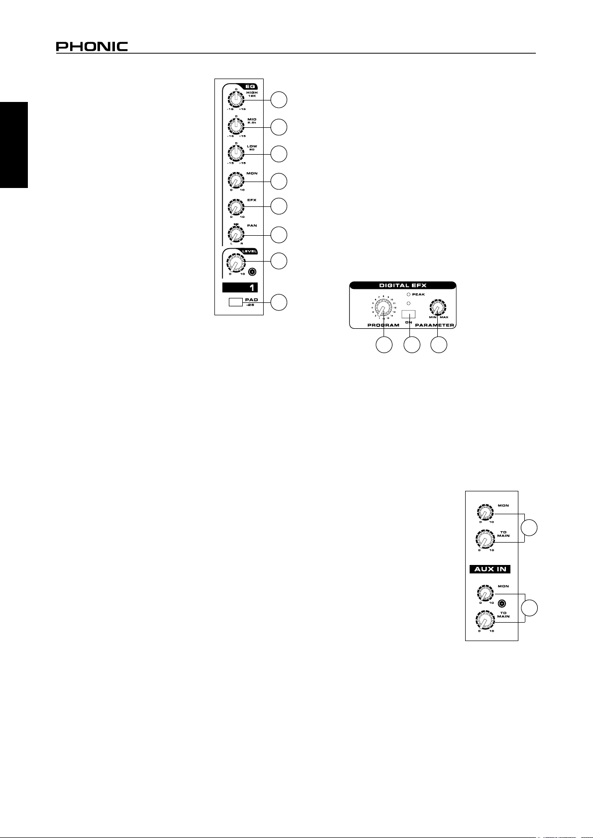
15. HIGH (High Frequency) Control
This control is used to give a shelving boost
or cut of ±15 dB to high frequency (12 kHz)
sounds. This will adjust the amount of
treble included in the audio of the channel,
adding strength and crispness to sounds
such as guitars, cymbals, synthesizers and
Michael Jackson.
16. MID (Middle Frequency) Control
This control is used to provide a peaking
style of boost and cut to the level of middle
frequency sounds at a range of ±15 dB.
Changing middle frequencies of an audio
feed can be rather difcult when used in
a professional audio mix, as it is usually
more desirable to cut middle frequency
sounds rather than boost them, soothing
overly harsh vocal and instrument sounds
in the audio.
17. LOW (Low Frequency) Control
This control is used to give a shelving boost or cut of ±15 dB to
low frequency (80 Hz) sounds. This will adjust the amount of bass
included in the audio of the channel, and bring more warmth and
punch to drums, bass guitars and Isaac Hayes.
18. MON (Monitor) Level Control
This control alters the signal level that is being sent to the Monitor
mixing buses, the signal of which is suitable for connecting stage
monitors, allowing artists to listen to the music that is being playing.
19. EFX (Effect) Level Control
This control alters the signal level that is sent to the EFX output,
which can be used in conjunction with external signal processors
(this signal of which can be returned to mixer via the stereo return
inputs), or simply as additional auxiliary outputs for any means
required. These controls also adjust the level of audio that is sent
to the built-in digital effect panel.
20. Pan / Balance Controls
This alternates the degree or level of audio that the left and right
side of the main mix should receive. On mono channels, this control
will adjust the level that the left and right should receive, where as
on a stereo channel, adjusting the BAL control will attenuate the
left or right audio signals accordingly.
21. Channel Level Control
This control will alter the signal level that is sent from the
corresponding channel to the Main mixing bus.
22. PAD -25 Button
The PAD -25 button, located above the 1/4” Phone Jack of mono
channels, is used to attenuate the input signal by 25 dB. This
should only be pushed in when using line-level input devices.
Digital Effect Processor
23. Effects On Button and Indicator
Pushing this button will turn the built-in effect processor on and off.
When the effect processor is activated, the corresponding LED will
light up to indicate so.
24. Program Control
This control will allow users to select one of the 16 built-in digital
effects of the Powerpod powered mixer. The effect names that
correspond with the numbers can be found on the top of the
mixer’s face, or in the digital effect table.
25. Parameter Control
Turning this control will adjust the one main parameter of the
selected effect. Each effect’s parameter can be found on the
digital effect table.
Master Section
26. EFX To Monitor Control
This controls the level of the processed signal from the built-in
effect processor, that is sent to the Monitor mixing bus.
27. EFX To Main Control
This controls the level of the processed signal from the built-in
effect processor, that is sent to the Main L/R mixing bus.
28. AUX In Controls
The Powerpod 1062 and 1082 models feature
2 AUX in Controls. One that adjusts the nal
level that is sent to the Monitor mixing bus
(the upper control), another that controls the
nal level that is sent to the Main L-R mixing
bus (the lower control).
29. Tape In
The Powerpod 1062 and 1082 models
feature 2 Tape in controls. One that adjusts
the nal level that is sent to the Monitor
mixing bus (the upper control), another that
controls the nal level that is sent to the Main
mixing bus (the lower control).
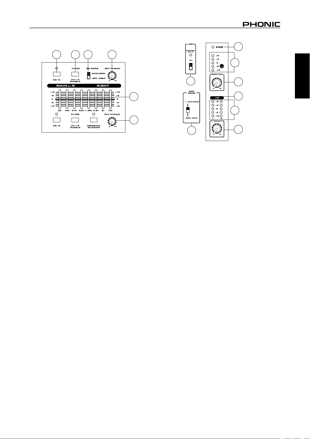
30. Graphic Equalizers
These graphic equalizer allows you to adjust the frequency
response of a signal, with a maximum of ±12 dB of signal boost
or cut for each of the frequencies. The Powepod 1062 and
1082 models all feature dual 10-band Graphic Equalizers. The
uppermost equalizer is for alteration of the Monitor signal (when
the EQ switch is in the appropriate position it becomes the Main
Left EQ, where the lower equalizer is for the Main L-R signal.
15
16
17
18
19
20
21
22
2324 25
28
29
5
POWERPOD 1062 PLUS / 1062R / 1062FR / 1082 PLUS / 1082R
English
31. EQ IN and Indicator
This button activates the graphic equalizer in which it accompanies.
The corresponding LED indicator illuminates when the EQ is
activated.
32. Rumble Filter (Powerpod 1082 models only)
This button activates a rumble lter on channels 1 through 6 to
help remove low frequency sounds that could affect input signals.
33. EQ Select Switch
This switch enables you to select the way you utilize the pair of
Equalizers on these models. when the switch is in the uppermost
position it enables you to use the top equalizer for the Monitor
signal, and the bottom equalizer for the Main L/R signal; the lower
position enables the equalizers to be used for the Main Left and
Right signals.
34. Phantom Power Switch and Indicator
When this switch is in the on position it activates +48V of phantom
power for the XLR inputs on channels 1 to 6, allowing condenser
microphones to be used on these channels. The corresponding
LED will illuminate when the Master Phantom Power is activated.
35. Amp Select Switches
This switches control the activity of the built-in power amp,
enabling the user to alternate between the different signals which
can be processed by the built-in power amp and routed to the
speaker outputs on the rear of the device. This switch allows you
to select from: Main/Monitor – taking the monitor and main signals
and directing them to the appropriate speaker outputs – Main L /
Main R – using the Main L/R signal to feed the speaker outputs.
36. Monitor Level Control
This rotary control allows the user to adjust the nal signal level
sent to all Monitor outputs.
37. Main Level Control
This rotary control allows the user to adjust the nal signal level
sent to the Main L-R and Speaker outputs.
38. Level Meter
These level meters give accurate indications of when audio levels
of the Main L/R stereo (or Main mono) and Monitor outputs reach
certain levels. The 0 dB indicator illuminates is approximately equal
to an output level of +4 dBu. It is suggested for the maximum use of
audio to set the various levels controls so that it sits steadily between
0 and the second highest level indicated on the Level Meter to make
full use of audio, while still maintaining fantastic clarity.
39. Limiters
These LED indicators illuminate when the power amplier’s built-in
limiters are activated, which effectively reduce signal levels when
they reach high levels that could prove to damage sound quality.
40. Power Indicator
This LED indicator illuminates when power of your Powerpod
mixer is activated.
31 32 33
26
30
27
34
35
37
39
36
40
38
38
 Loading...