


SAFTY PRECAUTIONS
SAFETY PRECAUTIONS!
WARNING - TO REDUCE THE RISK OF FIRE OR ELECTRIC SHOCK, DO NOT
EXPOSE THIS UNIT TO RAIN OR MOISTURE.
Do not allow water or liquids to be spilled into this unit. If the unit has been exposed to rain or liquids, please unplug the power cord immediately from the outlet (with DRY HANDS) and get a qualified service technician to check it. Keep this unit away from heat sources such as radiators, heat registers, stoves, etc.
This unit contains no user-serviceable parts. Refer all service needs to a qualified service engineer through a Phonic dealer.
This triangle on your component alerts you to the presence of uninsulated “ dangerous voltage” inside the enclosure that may be sufficient to constitute a risk of shock.
This triangle on your component alerts you to important operating and maintenance instructions in this accompanying literature.
CAUTION:
TO REDUCE THE RISK OF ELECTRIC SHOCK, DO NOT REMOVE COVERS (OR BACK). NO USER-SERVICEABLE PARTS ARE INSIDE. REFER ALL SERVICING TO A QUALIFIED SERVICE PERSONNEL.
Keep this unit clean by using a soft dry brush and occasionally wiping it with a damp cloth. Do not use any other solvents, which may damage the paint or plastic parts. Regular care and inspection will be rewarded by a long life and maximum reliability.
Your Phonic MM1002 / MM1202 was carefully packed at the manufacturing site and the packing box was designed to protect the unit from rough handling. We recommend that you carefully examine the packaging and its contents for any signs of physical damage, which may have occurred during transportation.
If the unit is damaged: Notify your dealer and the shipping company immediately. Claims for damage or replacement may not be granted if not reported properly or in a timely manner.
Page 2 |
MM1002 / MM1202 USER’S MANUAL |
PHONIC CORPORATION |
|
|
|

CONTENTS
INTRODUCTION............................................ |
4 |
CTRL RM................................... |
13 |
|
|
REC................................................ |
13 |
FEATURES............................................... |
4 |
2T RTN...................................................... |
13 |
|
|
EFX OUT CONTROL(MM1202 ONLY)............ |
13 |
GETTING STARTED....................................... |
4 |
AUX OUT CONTROL(MM1202 ONLY)........... |
13 |
|
|
+48V PHANTOM PWR.............................. |
13 |
CONNECTING IT UP................................. |
5 |
LED LEVEL METERS.................................. |
13 |
|
|
HEADPHONE/STEREO INDICATION |
|
TYPICAL CONNECTING LEADS..................... |
6 |
SELECT BUTTON....................................... |
13 |
|
|
MS/ST SELECT BUTTON........................... |
13 |
UNBALANCED & BALANCED......................... |
7 |
2T RTN SIGNAL PATH SELECT BUTTON..... |
13 |
|
|
AUX SIGNAL PATH SELECT BUTTON.......... |
14 |
CHANNEL STRIP DESCRIPTION..................... |
8 |
CTRL RM LEVEL................................... |
14 |
MIC/LINE MM1002(CH1~2)/MM1202(CH1~4)....... |
8 |
HEADPHONE..................................... |
14 |
GAIN........................................................... |
8 |
MAIN L/R FADER.............................. |
14 |
EQUALIZER.................................................. |
8 |
|
|
AUX ................................................................ |
9 |
REAR PANEL DESCRIPTION............... |
14 |
EFX(MM1202 ONLY)...................................... |
9 |
POWER SUPPLY INPUT SOCKET.............. |
14 |
PEAK................................................... |
9 |
POWER ON/OFF SWITCH.......................... |
14 |
PAN........................................................... |
9 |
|
|
LEVEL................................................. |
10 |
INITIAL SETUP........................................... |
15 |
M-S SWITCH........................................ |
10 |
|
|
M-S STEREO RECORDING.......................... |
10 |
APPLICATIONS..................................... |
16 |
WHAT IS A CARDIOID MICROPHONE?............. |
11 |
STANDARD CONNECTIONS................... |
16 |
WHAT IS A FIGURE-8 MICROPHONE?............. |
11 |
LIVE BAND SETTING............................ |
17 |
STEREO INPUT................................................. |
12 |
|
|
+4/-10 SWITCH.......................................... |
12 |
DIMENSIONS ............................................ |
18 |
BAL(BALANCE)CONTROL........................... |
12 |
|
|
|
|
SPECIFICATIONS..................................... |
19 |
MASTER SECTION DESCRIPTION............... |
13 |
|
|
MAIN OUT...................................... |
13 |
SYSTEM BLOCK DIAGRAMS..................... |
21 |
EFX OUT(MM1202 ONY).............................. |
13 |
|
|
AUX OUT........................................... |
13 |
REFERENCE BOOKS.................................. |
22 |
PHONIC CORPORATION |
MM1002 / MM1202 USER’S MANUAL |
Page 3 |
|
|
|

INTRODUCTION / FEATURES / GETTING STARTED
INTRODUCTION |
MM1202 |
|||
Congratulations on your purchase of the MM serial |
l |
12 standard inputs |
||
Mixer. The MM serial mixer is built into a rugged |
l |
4-balanced Mic/Line input channels with 3 band |
||
construction, which is ideal for small live gigs, re- |
|
EQ. Able to accept a wide range of Microphone |
||
cording and fixed PA installations. In order to get |
|
and Line level from Neutrik combo connector |
||
the best performance from the mixer, please read |
l |
4 stereo inputs with +4/-10 input sensitivity |
||
this user’s manual carefully. Please familiarize your- |
|
selector. |
||
self with the new and different functions on this mixer. |
l |
Additional 2T return inputs, for CD playback or |
||
|
|
|
link to another submixer |
|
|
|
l Global +48V phantom power switch on 1-4 |
||
FEATURES |
|
channel at master section |
||
|
|
|
||
MM1002 |
l Separate Mix and Control Room output |
|||
|
M/S switch |
|||
|
10 standard inputs |
l |
||
l |
l |
Record output |
||
l 2 balanced Mic/Line input channels with 2 band |
||||
l |
Meter indicator switch allows meter to show MS/ |
|||
|
EQ. Able to accept a wide range of Microphone |
|||
|
|
ST/Headphone level |
||
|
and Line level from Neutrik combo connector |
|
||
|
l |
Headphone output |
||
l 4 stereo inputs with +4/-10 input sensitivity se- |
||||
l |
Peak indicators on each mono input channel |
|||
|
lector |
|||
|
|
|
||
l Additional 2T return inputs, for CD playback or |
|
|
||
|
link to submixer |
GETTING STARTED |
||
|
|
|||
l Global +48V phantom power switch on 1-2 chan- |
1. Check the AC voltage before connecting the AC |
|||
|
nel at master section |
|||
|
|
plug. This product is equipped with a 3-wire |
||
l Separate Mix and Control Room output |
|
|||
|
grounding type plug; this is a safety feature and |
|||
l |
M/S switch |
|
||
|
should not be defeated. Proper grounding is a |
|||
l |
Record output |
|
||
|
necessary practice to prevent electric shock |
|||
l Meter indicator switch allows meter to show MS/ |
|
|||
|
hazards to the operator, the microphone user, |
|||
|
ST/Headphone level |
|
||
|
|
and the musicians who are wired to this unit. |
||
l |
Headphone output |
|
||
|
|
|||
l Peak indicators on each mono input channel |
2. |
Before switching on the main power, keep all the |
|
output fader all the way down to prevent damage |
|
|
|
|
|
|
or excessive noise caused by bad level |
|
|
adjustment, wrong wiring, defective cables, or bad |
|
|
connection. |
|
3. |
Always turn on the mixer before the power |
|
|
amplifier; turn off the mixer after the amplifier. |
|
4. |
Always turn off the unit before connecting and |
|
|
disconnecting the unit from the power source. |
|
5. |
Never use solvents to clean the unit. Clean with |
|
|
a soft, dry cloth. |
Page 4 |
MM1002 / MM1202 USER’S MANUAL |
PHONIC CORPORATION |
|
|
|

CONNECTING IT UP
CONNECTING IT UP
|
|
|
|
|
|
|
|
|
|
|
|
|
|
|
|
|
|
|
|
|
|
|
|
|
|
|
|
|
|
|
|
|
|
|
|
|
|
|
|
|
|
|
|
|
|
|
|
|
|
|
|
|
|
|
|
|
|
|
|
|
|
|
|
|
|
|
|
|
|
|
|
|
|
|
|
|
|
|
|
|
|
|
|
|
|
|
|
|
|
|
|
|
|
|
|
|
|
|
|
|
|
|
|
|
|
|
|
|
|
|
|
|
|
|
|
|
|
|
|
|
|
|
|
|
|
|
|
|
|
|
|
|
|
|
|
|
|
|
|
|
|
|
|
|
|
|
|
|
|
|
|
|
|
|
|
|
|
|
|
|
|
|
|
|
|
|
|
|
|
|
|
|
|
|
|
|
|
|
|
|
|
|
|
|
|
|
|
|
|
|
|
|
|
|
|
|
|
|
|
|
|
|
|
|
|
|
|
|
|
|
|
|
|
|
|
|
|
|
|
|
|
|
|
|
|
|
|
|
|
|
|
|
|
|
|
|
|
|
|
|
|
|
|
|
|
|
|
|
|
|
|
|
|
|
|
|
|
|
|
|
|
|
|
|
|
|
|
|
|
|
|
|
|
|
|
|
|
|
|
|
|
|
|
|
|
|
|
|
|
|
|
|
|
|
|
|
|
|
|
|
|
|
|
|
|
|
|
|
|
|
|
|
|
|
|
|
|
|
|
|
|
|
|
|
|
|
|
|
|
|
|
|
|
|
|
|
|
|
|
|
|
|
|
|
|
|
|
|
|
|
|
|
|
|
|
|
|
|
|
|
|
|
|
|
|
|
|
|
|
|
|
|
|
|
|
|
|
|
|
|
|
|
|
|
|
|
|
|
|
|
|
|
|
|
|
|
|
|
|
|
|
|
|
|
|
|
|
|
|
|
|
|
|
|
|
|
|
|
|
|
|
|
|
|
|
|
|
|
|
|
|
|
|
|
|
|
|
|
|
|
|
|
|
|
|
|
|
|
|
|
|
|
|
|
|
|
|
|
|
|
|
|
|
|
|
|
|
|
|
|
|
|
|
|
|
|
|
|
|
|
|
|
|
|
|
|
|
|
|
|
|
|
|
|
|
|
|
|
|
|
|
|
|
|
|
|
|
|
|
|
|
|
|
|
|
|
|
|
|
|
|
|
|
|
|
|
|
|
|
|
|
|
|
|
|
|
|
|
|
|
|
|
|
|
|
|
|
|
|
|
|
|
|
|
|
|
|
|
|
|
|
|
|
|
|
|
|
|
|
|
|
|
|
|
|
|
|
|
|
|
|
|
|
|
|
|
|
|
|
|
|
|
|
|
|
|
|
|
|
|
|
|
|
|
|
|
|
|
|
|
|
|
|
|
|
|
|
|
|
|
|
|
|
|
|
|
|
|
|
|
|
|
|
|
|
|
|
|
|
|
|
|
|
|
|
|
|
|
|
|
|
|
|
|
|
|
|
|
|
|
|
|
|
|
|
|
|
|
|
|
|
|
|
|
|
|
|
|
|
|
|
|
|
|
|
|
|
|
|
|
|
|
|
|
|
|
|
|
|
|
|
|
|
|
|
|
|
|
|
|
|
|
|
|
|
|
|
|
|
|
|
|
|
|
|
|
|
|
|
|
|
|
|
|
|
|
|
|
|
|
|
|
|
|
|
|
|
|
|
|
|
|
|
|
|
|
|
|
|
|
|
|
|
|
|
|
|
|
|
|
|
|
|
|
|
|
|
|
|
|
|
|
|
|
|
|
|
|
|
|
|
|
|
|
|
|
|
|
|
|
|
|
|
|
|
|
|
|
|
|
|
|
|
|
|
|
|
|
|
|
|
|
|
|
|
|
|
|
|
|
|
|
|
|
|
|
|
|
|
|
|
|
|
|
|
|
|
|
|
|
|
|
|
|
|
|
|
|
|
|
|
|
|
|
|
|
|
|
|
|
|
|
|
|
|
|
|
|
|
|
|
|
|
|
|
|
|
|
|
|
|
|
|
|
|
|
|
|
|
|
|
|
|
|
|
|
|
|
|
|
|
|
|
|
|
|
|
|
|
|
|
|
|
|
|
|
|
|
|
|
|
|
|
|
|
|
|
|
|
|
|
|
|
|
|
|
|
|
|
|
|
|
|
|
|
|
|
|
|
|
|
|
|
|
|
|
|
|
|
|
|
|
|
|
|
|
|
|
|
|
|
|
|
|
|
|
|
|
|
|
|
|
|
|
|
|
|
|
|
|
|
|
|
|
|
|
|
|
|
|
|
|
|
|
|
|
|
|
|
|
|
|
|
|
|
|
|
|
|
|
|
|
|
|
|
|
|
|
|
|
|
|
|
|
|
|
|
|
|
|
|
|
|
|
|
|
|
|
|
|
|
|
|
|
|
|
|
|
|
|
|
|
|
|
|
|
|
|
|
|
|
|
|
|
|
|
|
|
|
|
|
|
|
|
|
|
|
|
|
|
|
|
|
|
|
|
|
|
|
|
|
|
|
|
|
|
|
|
|
|
|
|
|
|
|
|
|
|
|
|
|
|
|
|
|
|
|
|
|
|
|
|
|
|
|
|
|
|
|
|
|
|
|
|
|
|
|
|
|
|
|
|
|
|
|
|
|
|
|
|
|
|
|
|
|
|
|
|
|
|
|
|
|
|
|
|
|
|
|
|
|
|
|
|
|
|
|
|
|
|
|
|
|
|
|
|
|
|
|
|
|
|
|
|
|
|
|
|
|
|
|
|
|
|
|
|
|
|
|
|
|
|
|
|
|
|
|
|
|
|
|
|
|
|
|
|
|
|
|
|
|
|
|
|
|
|
|
|
|
|
|
|
|
|
|
|
|
|
|
|
|
|
|
|
|
|
|
|
|
|
|
|
|
|
|
|
|
|
|
|
|
|
|
|
|
|
|
|
|
|
|
|
|
|
|
|
|
|
|
|
|
|
|
|
|
|
|
|
|
|
|
|
|
|
|
|
|
|
|
|
|
|
|
|
|
|
|
|
|
|
|
|
|
|
|
|
|
|
|
|
|
|
|
|
|
|
|
|
|
|
|
|
|
|
|
|
|
|
|
|
|
|
|
|
|
|
|
|
|
|
|
|
|
|
|
|
|
|
|
|
|
|
|
|
|
|
|
|
|
|
|
|
|
|
|
|
|
|
|
|
|
|
|
|
|
|
|
|
|
|
|
|
|
|
|
|
|
|
|
|
|
|
|
|
|
|
|
|
|
|
|
|
|
|
|
|
|
|
|
|
|
|
|
|
|
|
|
|
|
|
|
|
|
|
|
|
|
|
|
|
|
|
|
|
|
|
|
|
|
|
|
|
|
|
|
|
|
|
|
|
|
|
|
|
|
|
|
|
|
|
|
|
|
|
|
|
|
|
|
|
|
|
|
|
|
|
|
|
|
|
|
|
|
|
|
|
|
|
|
|
|
|
|
|
|
|
|
|
|
|
|
|
|
|
|
|
|
|
|
|
|
|
|
|
|
|
|
|
|
|
|
|
|
|
|
|
|
|
|
|
|
|
|
|
|
|
|
|
|
|
|
|
|
|
|
|
|
|
|
|
|
|
|
|
|
|
|
|
|
|
|
|
|
|
|
|
|
|
|
|
|
|
|
|
|
|
|
|
|
|
|
|
|
|
|
|
|
|
|
|
|
|
|
|
|
|
|
|
|
|
|
|
|
|
|
|
|
|
|
|
|
|
|
|
|
|
|
|
|
|
|
|
|
|
|
|
|
|
|
|
|
|
|
|
|
|
|
|
|
|
|
|
|
|
|
|
|
|
|
|
|
|
|
|
|
|
|
|
|
|
|
|
|
|
|
|
|
|
|
|
|
|
|
|
|
|
|
|
|
|
|
|
|
|
|
|
|
|
|
|
|
|
|
|
|
|
|
|
|
|
|
|
|
|
|
|
|
|
|
|
|
|
|
|
|
|
|
|
|
|
|
|
|
|
|
|
|
|
|
|
|
|
|
|
|
|
|
|
|
|
|
|
|
|
|
|
|
|
|
|
|
|
|
|
|
|
|
|
|
|
|
|
|
|
|
|
|
|
|
|
|
|
|
|
|
|
|
|
|
|
|
|
|
|
|
|
|
|
|
|
|
|
|
|
|
|
|
|
|
|
|
|
|
|
|
|
|
|
|
|
|
|
|
|
|
|
|
|
|
|
|
|
|
|
|
|
|
|
|
|
|
|
|
|
|
|
|
|
|
|
|
|
|
|
|
|
|
|
|
|
|
|
|
|
|
|
|
|
|
|
|
|
|
|
|
|
|
|
|
|
|
|
|
|
|
|
|
|
|
|
|
|
|
|
|
|
|
|
|
|
|
|
|
|
|
|
|
|
|
|
|
|
|
|
|
|
|
|
|
|
|
|
|
|
|
|
|
|
|
|
|
|
|
|
|
|
|
|
|
|
|
|
|
|
|
|
|
|
|
|
|
|
|
|
|
|
|
|
|
|
|
|
|
|
|
|
|
|
|
|
|
|
|
|
|
|
|
|
|
|
|
|
|
|
|
|
|
|
|
|
|
|
|
|
|
|
|
|
|
|
|
|
|
|
|
|
|
|
|
|
|
|
|
|
|
|
|
|
|
|
|
|
|
|
|
|
|
|
|
|
|
|
|
|
|
|
|
|
|
|
|
|
|
|
|
|
|
|
|
|
|
|
|
|
|
|
|
|
|
|
|
|
|
|
|
|
|
|
|
|
|
|
|
|
|
|
|
|
|
|
|
|
|
|
|
|
|
|
|
|
|
|
|
|
|
|
|
|
|
|
|
|
|
|
|
|
|
|
|
|
|
|
|
|
|
|
|
|
|
|
|
|
|
|
|
|
|
|
|
|
|
|
|
|
|
|
|
|
|
|
|
|
|
|
|
|
|
|
|
|
|
|
|
|
|
|
|
|
|
|
|
|
|
|
|
|
|
|
|
|
|
|
|
|
|
|
|
|
|
|
|
|
|
|
|
|
|
|
|
|
|
|
|
|
|
|
|
|
|
|
|
|
|
|
|
|
|
|
|
|
|
|
|
|
|
|
|
|
|
|
|
|
|
|
|
|
|
|
|
|
|
|
|
|
|
|
|
|
|
|
|
|
|
|
|
|
|
|
|
|
|
|
|
|
|
|
|
|
|
|
|
|
|
|
|
|
|
|
|
|
|
|
|
|
|
|
|
|
|
|
|
|
|
|
|
|
|
|
|
|
|
|
|
|
|
|
|
|
|
|
|
|
|
|
|
|
|
|
|
|
|
|
|
|
|
|
|
|
|
|
|
|
|
|
|
|
|
|
|
|
|
|
|
|
|
|
|
|
|
|
|
|
|
|
|
|
|
|
|
|
|
|
|
|
|
|
|
|
|
|
|
|
|
|
|
|
|
|
|
|
|
|
|
|
|
|
|
|
|
|
|
|
|
|
|
|
|
|
|
|
|
|
|
|
|
|
|
|
|
|
|
|
|
|
|
|
|
|
|
|
|
|
|
|
|
|
|
|
|
|
|
|
|
|
|
|
|
|
|
|
|
|
|
|
|
|
|
|
|
|
|
|
|
|
|
|
|
|
|
|
|
|
|
|
|
|
|
|
|
|
|
|
|
|
|
|
|
|
|
|
|
|
|
|
|
|
|
|
|
|
|
|
|
|
|
|
|
|
|
|
|
|
|
|
|
|
|
|
|
|
|
|
|
|
|
|
|
|
|
|
|
|
|
|
|
|
|
|
|
|
|
|
|
|
|
|
|
|
|
|
|
|
|
|
|
|
|
|
|
|
|
|
|
|
|
|
|
|
|
|
|
|
|
|
|
|
|
|
|
|
|
|
|
|
|
|
|
|
|
|
|
|
|
|
|
|
|
|
|
|
|
|
|
|
|
|
|
|
|
|
|
|
|
|
|
|
|
|
|
|
|
|
|
|
|
|
|
|
|
|
|
|
|
|
|
|
|
|
|
|
|
|
|
|
|
|
|
|
|
|
|
|
|
|
|
|
|
|
|
|
|
|
|
|
|
|
|
|
|
|
|
|
|
|
|
|
|
|
|
|
|
|
|
|
|
|
|
|
|
PHONICCORPORATION |
MM1002 / MM1202 USER’S MANUAL |
Page 5 |
||||||||||||||||||||||||||||||||||||||||||
|
|
|
|
|
|
|
|
|
|
|
|
|
|
|
|
|
|
|
|
|
|
|
|
|
|
|
|
|
|
|
|
|
|
|
|
|
|
|
|
|
|
|
|
|
TYPICAL CONNECTING LEADS
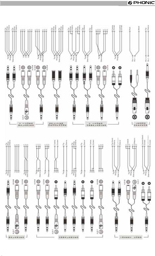
TYPICAL CONNECTING LEADS
Page 6 |
MM1002 / MM1202 USER’S MANUAL |
PHONIC CORPORATION |
|
|
|

UNBALANCED&BALANCED
UNBALANCED & BALANCED |
interference. |
Most of the mistakes in audio installations are due to incorrect and defective audio connections. In order to perfectly complete your installation. Please pay special attention to the following section unless you are already familiar with balanced/unbalanced operations.
WHAT IS AN UNBALANCED LINE?
You can find this kind of system in most of home audio-video systems. They have one conductor to carry signal, and another conductor for a ground. Normally, for lower level signals, the ground conductor shields the signal conductor.
WHAT IS A BALANCED LINE?
A balanced system transmits signal via 2 conductors plus one ground shielding conductor. The 2 signal conductors carry the same signal but out of phase. For the balanced input stage, the amplifier will boost the difference between the 2 signal conductors and remove the identical part (known as common mode signal) of the 2 signals . Because the real signal is carried by the 2 conductors out of phase, so it is perfectly carried to the input. At the same time, interference that occurs during transmission will be identical (common mode). Because the signal conductors are run together, there is no chance they can be different, and all the interference will be removed by the balanced input amplifier.
THE DIFFERENCE BETWEEN TWO
OPERATIONS:
Because of the common mode interference immunity of a balanced system, the ground conductor doesn’t need to carry any electrical current, which means the ground of the 2 connected units has an identical ground level which is vital to an interference free system. Let’s look back at the unbalanced system. The signal electrical current goes from the signal conductor to the ground conductor. The ground level of the 2 connected units are not identical. This means the system is more easily inclined to noise
Running long cables is easy for a balanced system but difficult for an unbalanced system. A Lower noise level is a characteristic of a balanced system.
Because a balanced system needs 2 conductors for the signal and 1 conductor for the ground, a minimum of 3 conductors are needed for wiring a balanced system. So a dedicated system separates the ground and shields the 2 conductors.
Please read following section to properly wire for balanced and unbalanced systems:
THE CORRECT WIRING FOR BALANCED
OPERATION:
Always connect the main power with 3 plugs. Make sure the power system ground is working properly. Don’t use a ground insulator plug adapter without properly connecting the ground individually. This is vital to making a successful audio system connection.
Always connect the ground pin (PIN 1 in XLR) to the source unit, and disconnect this pin on the destination unit. This connection topology is to avoid creating a grounding loop between the signal and power ground. Utilize only the power ground, because it always has a lower resistance and better distribution than the signal ground.
If there is hum, a possible reason is a bad ground connection for the system. In case you can not find the fault, try connecting the ground pin of the input connectors. If the hum is reduced or eliminated, check your power grounding system. Special attention is needed when you use the equipment racks with some distance between them, and/or use a large quantity of power amplifiers. Check the power ground between the racks and power distribution strips with your electrical supply engineer. Make sure there is one, and only one, proper ground point for the audio system (or connected video system).
PHONICCORPORATION |
MM1002 / MM1020 USER’S MANUAL |
Page 7 |
|
|
|
CHANNEL STRIP DESCRIPTION
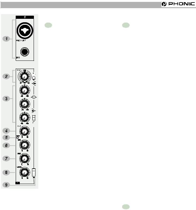
CHANNEL STRIP DESCRIPRION
1 MIC/LINE MM1002(Ch1~2)/
MM1202 (Ch1~4)
The Microphone is via a combo connector, which allows the connections of XLR or 1/4 “ type phone jack. Please use only professional low impedance microphone and properly wired cable for best result. When the 1/4“ phone jack plug into the combo connector, the connection can be microphone or line level signal, we can change the input trim for MIC or LINE by using the LINE/MIC slide-switch to set the different TRIM accordingly. However, the phantom power is only available for the XLR connection. Never turn on the phantom power when you have line level source connected to the XLR connector.
48V PHANTOM POWER
+48V Phantom Power is available on each microphone input channel. All faders should be all the way down when switching on/off the phantom power, in order to prevent excessive noise to stage monitor speakers and main speakers; Phantom powered mics should not be plugged in with the +48V switched on.
INS
The INSERT is a break point in the input channel signal path. It allows the signal to be taken out from the mixer, through an external equipment such as a compressor, and then back to the mixer to continue the final mix output.
2 GAIN
This rotary knob adjusts the channel signal level. Too high, the signal will distort as it overloads the channel. Too low, the level of back hiss will be more noticeable and there might be insufficient signal level to the output of the mixer. Proper gain setting allows the mixer to work in the best operating level, adjusts the gain when signal presents to the highest level without triggering the peak LED. That is the most appropriate position.
This gain has two kinds of indication to suit mic or line input, when you use mic input, please read inside ring from +10~+60 dB, if you use line input, please read outside ring from -10~+40dB.
LINE / MIC SWITCH
When you use the channel for microphone, either through XLR or Phone plug, please switch to MIC. If you use the channel for line level source, either through XLR or Phone plug, please switch to the LINE. This switch will set the appropriate gain range for the input signal.
3 EQUALIZER
HIGH
Turn right to boost high frequency, adding crispness to cymbals, vocals and electronic instruments. Turn left to cut this frequency, reducing sibilance or hiss. The control has a shelving response that gives 15dB of boost or cut at 12KHZ.
Page 8 |
MM1002 / MM1202 USER’S MANUAL |
PHONICCORPORATION |
|
|
|
 Loading...