


IntelliVue

Philips Telemetry System
Quick Reference Service Guide
Contents
This Quick Reference Service Guide is a pocket sized
quick reference of the mos t used informat ion for the
Philips Telemetry System. It includes th e following:
Troubleshooting Overview. . . . . . . . . . . . . . . 2
Transmitter Non-RF Application Problems . . 5
Transmitter SpO2 Problems . . . . . . . . . . . . 12
Receiver Mainframe/System Faults . . . . . . 15
Other Problems . . . . . . . . . . . . . . . . . . . . . . 22
RF Troubleshooting Procedures . . . . . . . . . 24
RF Troubleshooting Tools . . . . . . . . . . . . . . 33
Part Lists . . . . . . . . . . . . . . . . . . . . . . . . . . . 38
Contents
1
Troubleshooting Overview
Troubleshooting Map
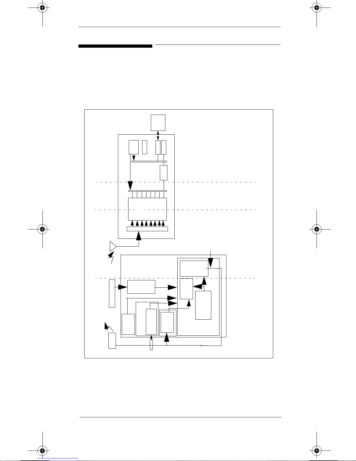
Figure 1 provides an overview map of areas of the
Telemetry System where problems can occur.
Sta tion
Central
CPC
SDN
Power
Supply
Utility
Digital Backplane
- Receiver Mainframe
Receiver
- System
Non-RF
M2604A Receiver Ma inframe
Digital
Section
Module
(up to 8)
Receiver
RF
Section
Rack
Interface
Receiver Backplane
Antenna Distribution Board
Trans mits
Via Leadset
- NO DATA FROM BED
- No Receiver
-No Power at Receiver Main-
frame
Malfunction
- Receiver
RF
- No Signal
- Tel Cannot Analyze
- Weak Signal
- Invalid Signal E01
RF
M2601A
Transmitter
2
PCB
SpO
Transducer
Button
Patient
- Transmitter non-RF
Leadset
- Application
Switch
3/5 Leadset
Front En d Assembly
ECG PCB
tion
Sec-
Digital
Section
and Battery
Power Supply
Main PCB
- LEADS OFF
- Interference
INOPs
2
- BATTERY INOPs
-ECG EQUIP MALF INOP
-TRANSMITTER MALF INOP
-SpO
TRANSMITTER OFF
INVALID LEADSET
ARRHY REQUIRED
Figure 1 Telemetry System Troubleshooting Map
2
Troubleshooting Overview

Troubleshooting Messages
The following Troubleshooting Messages are de scribed
in the following sections on the page indicated.
Message Page
LEADS OFF INOP
TRANSMITTER OFF INO
INVALID LEADSET INOP
NO SIGNAL INOP and an RF OUT OF LOCK INOP
at Telemetry Service Tool or Wave Viewer
Battery INOPs
ECG EQUIP MALF INOP
TRANSMITTER MALF INOP
ARRHY REQUIRED INOP
ECG EQUIP MALF INOP
SpO2 ERRATIC INOP
SpO2 INTERFERENCE INOP
SpO2 NO TRANSDUCER INOP
SpO2 NOISY SIGNAL INOP
5
6
7
8
9
11
11
11
11
12
13
13
14
SpO2 NON-PULSATILE INOP
SpO2 TRANS MALF INOP
Power does not come on when Receiver Mainframe
Power On/Off Button is pressed
NO DATA FROM BED INOP
NO RECEIVER INOP
RECEIVER MALF INOP
Transmitter Button is pressed, but desired result
does not occur
INVALID SIGNAL E01INOP
Troubleshooting Overview
14
14
15
15
20
21
22
24
3
Message Page
Frequent Dropouts and NO SIGNAL, WEAK
25
SIGNAL, and TEL CANNOT ANALYZE INOPs on a
Single Channel
Frequent Dropouts and NO SIGNAL, WEAK
29
SIGNAL, and TEL CANNOT ANALYZE INOPs with
Multiple Channels
Frequent Dropouts along with TEL CANNOT
30
ANALYZE and INTERFERENCE INOPs
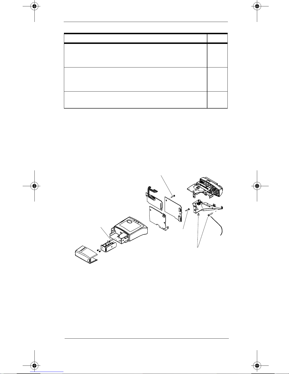
Transmitter Torque Requirements
If the transmitter is disassembled, certain screws must be
re-installed at specific torqu e specifications.
shows the torque requirements in the transmitt er .
Conversion Chart
2 inch-pounds = 0.23 joules
3 inch-pounds = 0.34 joules
6 inch-pounds = 0.68 joules
3 inch-
pounds
Figure 2
6 inch-
pounds
3 inch-
pounds
2 inch-
pounds
Figure 2 Torque Requirements
4
Troubleshooting Overview

Transmitter Non-RF Application
Problems
LEADS OFF INOP
This INOP generally means that one of the patient leads
has fallen off the patient. It can also indicate a fault
within the transmitter.
1. A lead may have become disconnected from the
electrode. Go to the transmitter generating the
INOP and m ake certain that all leads are connected
to the electrodes on the patient’s body. The LEDs
on the front of the transmitter should be off if all
lead wires are attached properly.
If the leads are correctly connected, use the
Telemetry Service Tool or Wave Viewer at the
bedside to make cert ain there is a good waveform.
The transmitter can also be connected to a patient
simulator, if this is more convenient. Using the
Telemetry Service Tool or Wave Viewer, check the
following:
a. All available leads. If there is an ECG waveform
but no LEADS OFF-Check Transmitter INOP
on the Telemetry Service Tool or Wave Viewer,
the leads are connected.
b. If there is not a good waveform, check the leads
again and make certain they are applied properly
before continuing with the procedures. Proper
application of electrodes includes:
– Proper skin preparation.
– Using “moist electrodes”. I f the gel on the
electrodes is not mo i st, the electrodes are too
dry to get a good signal.
– Making certain the c onnections are not dirty.
Transmitter Non-RF Application
5

2. If all leads are connected and there is not a good
signal, there may be a broken lead wire or the
connection between the leadset an d the t ra nsmi tte r
is compromised due to dirt or corrosion. Remove
the leadset and make c ertain the leadset connector
in the top of the transmitter is not dirty or
corroded. If it is, clea n or replace the conn ector.
If there is no dirt or corrosion, check that a leadset
with a telemetry leadset combiner block with latch
is used. Attach the leadset, (the leadset will click
when it locks). T hen change the lea dset. Check to
see if this fixes the problem.
If it does not, perform the fol lowing substeps:
a. Make certa i n the Front End Assembly to the
ECG PCB cable is connected (red tab
connector) properly or not broken. If the cable
is broken, replace the defective assembly
(ECG PCB or Fron t E nd Assembly).
b. Make cert ain that the 3/5 Lead Switch
connector is plugged-in prop er ly. If it is,
replace the ECG PCB.
c. If replacing the ECG PCB d oes not resolve the
problem, replace the Front End Assembly.
TRANSMITTER OFF INO
If there is a TRANSMITTER OFF message at the central
station, this ind i cat es th a t th e t ra nsmitter has determined
that there has been a
for the last 10 minutes or longer and has gone into RF
auto-shutoff.
1. Re-attach the leads to the patient. The transmitter
will turn on automatically.
LEADS OFF condition on all leads
6
Transmitter Non-RF Application Problems

INVALID LEADSET INOP
This indicates that the transmitter has either detected a
4-wire leadset or an EASI
leadset attached. Do the following:
1. If a 4-wire leadset has been installed, monit oring is
not possible. Replace wit h a 3- or 5 wire leadset.
a. If the transmitter is a standard ECG transmitter,
replace with a 3- or 5-wire leadset.
b. If the transmitter is an EASIä ECG transmitter, a
5-wire must be used.
2. If the transmitter i s an EA S Iä ECG transmitter , this
INOP will appear if monitoring is attempted while a
3-wire leadset is attached to the transmitter. Attach
a 5-wire leadset.
3. If this is a standard ECG transmitter, it may be
configured as an EASI
configuration of the EASI parame te r using the
transmitter Service Tool or Wave Viewer, as
follows:
ä ECG transmitter has a 3-wire
ä transmitter. Check the
– Telemetry Service Tool: Connect the service
tool to the transmitter and move to
Transmitter Configuration Screen Two
– Wave Viewer: Connect a 5-wire leadset to the
transmitter and to an ECG simulat or. Establish
communication between the Wave Viewer and
the transmitter. If the ECG waveform is
labelled
EASI and has the lead selections of
AI, AS and ES, th e transmitte r is co nfigured
for EASI operation. If the ECG waveform is
labelled
Lead and has the lead selections: I, II,
III, aVR, aVL, aVF, MCL and V, the transmitter
is configured for standard ECG.
– If the transmitter is configured incorrectly,
reconfigure it using the Service Tool.
Transmitter Non-RF Application
7

4. If the problem is not solv ed by Steps 1 - 3, then
there may be a problem wit h the leadset switches
not being detect ed properly.
a. Check where the leadset attaches for dirt and clean
as necessary. Leadset switches are located next to
the reference and chest (standard ECG) or
reference and “E” (EASI) lead wires.
b. The 3/5 lead switch may not be connected to the
ECG PCB properly.
c. Replace the Front-End Assembly
d. Replace the Main PCB.
NO SIGNAL INOP and an RF OUT OF LOCK
INOP at Telemetry Service Tool or Wave
Viewer
This INOP means that the transmitter has determined
that the phase-lock loop in the transmitter is no longer
functioning (This condition also generates a
INOP at the Central Station). Replace the Main PCB.
NO SIGNAL
8
Transmitter Non-RF Application Problems

Battery INOPs
This module tells how to deal with INOPs related to
battery operation. These INOPs are:
BATTERY WEAK
REPLACE BATTERY
Normally, either one of these INOP messages simply
indicat es the need to replace the battery in the
transmi tter generating the message. But, if the battery is
replaced and the me ssage still occurs, do the fo llowing.
Note
Battery life depends on the transmitter being used, the
battery type, and the SpO2 sample rate (SpO
monitored). Refer to the spec ifications in
Service and Reference Guide to determine what
the
battery life to expect.
is being
2
Appendix A of
If the battery life is less than expected, things to check
are:
• Remember that simply unplugging the SpO
transducer and turning SpO
not shut off the SpO
must be set to
Manual using the Telemetry Service
sampling. The sampling rate
2
off at the central does
2
2
Tool or Wave Viewer.
• After making a manual SpO
measurement using
2
the Telemetry Service Tool or W ave Viewer,
terminate th e mea surem ent by select ing
otherwise, the SpO
function does not shut off.
2
End STAT;
• Remove the batteries from the transmitter when
they are not in use. The RF auto-shutoff feature
does not save battery life because the circuitry is
constantly checking to see if the unit has been
connected to a patient.
Transmitter Non-RF Application
9

1. The battery could be inserted improperly. Check
that the terminals of the battery are oriented
correctly with the battery contacts.
2. Open the bat tery door and check the battery
contact s. If they are corroded, clean them. If they
appear damaged, replace the batte ry contacts.
Also, check the screws that connect the battery
contacts to the Case Assembly.
3. Zinc-air batteries cannot be used in transmitters
with SpO
hardware because zinc-air batteries
2
cannot reliably supply enough curren t at sta rt - up of
the transmitter to make sure the transmitter
functions properly. Even if SpO
monitored, if the transmitter has the SpO
is not being
2
2
hardware installed, a zinc-air battery cannot be
used. A lithium or alkaline battery must be used .
4. Remove the battery a nd separate the case assembly
from the transmitter’s internal electronics. Using an
ohmmeter, check the resistance from the battery
contact inside th e case to its corresponding
external battery contact. The resistance should be
less than 1 ohm. If it is not, replace the battery
contacts.
5. SpO
10
SpO
might be affecting the battery. Replace the
2
PCB.
2
Transmitter Non-RF Application Problems

ECG EQUIP MALF INOP
This INOP indicates that either a software incompatibility
has been found or a fault has been detected in the ECG
hardware in the transmitter.
1. If the transmitter i s an EA S I
INOP indicates that the software in either the
receiver mainframe or the central station cannot
process EASI
a. Update the software in the receiver mainframe and
the central station to a compatible revision.
b. Downgrade the transmitter firmware to a revision
compatible with the mainframe and central station
2. If SpO2, cannot be monitored, replace the ECG
PCB.
3. If changing the ECG PCB does not correct the
problem, replace the Main PCB.
ä ECG data. Do one of the following:
ä ECG transmitter, this
TRANSMITTER MALF INOP
This INOP indicates that the self-test has discovered a
problem with the i nternal, non-RF circ uitry of the
transmitter. The problem probably lies in the Digital ASIC
or the RAM section of the Main PCB. If this INOP
appears , replace the Main PCB.
ARRHY REQUIRED INOP
This message indicates that arrhythmia monitoring has
been turned off for an EASI ECG transmitter.
1. Turn arrhythmia monitoring O N at the Information
Center.
2. If arrhythmia monitoring is not desired, then a
standard ECG transmitter must be used.
Transmitter Non-RF Application
11

Transmitter SpO2 Problems
SpO2 EQUIP MALF INOP
This INOP indicates there is a problem with the SpO2
circuits associated with the transmitter. The following
procedure describes how to troubleshoot this proble m:
1. The tr ansducer may be bad. Change the transducer
to see if this resolves the problem.
2. The SpO
adapter cable may be faulty. Replace the
2
cable to see if this fixes the problem.
3. Open the transmitter and make certain the SpO
Connector cable is connected to the SpO
Board.
2
2
Make certain it is not damaged. If the cable is
damaged, replace the Front End Assembly.
4. Make certa in that the Main PCB to SpO
Board
2
ribbon cable is connected properly and is not
damaged. If th e cable is damaged, replace the Main
PCB.
5. Replace the SpO
Board.
2
6. If the problem persists, replace the Main PCB.
SpO2 ERRATIC INOP
This INOP indicates that the SpO2 measurem ents are
erratic. This could be due to a faulty transducer or
incorrect positioning of the transducer . It could also be
caused by optical shun ting if the transducer is too big or
too small. If this INOP appears, do the fo llowing.
1. Verify that the transducer is appropriate for the
patient’s weight. If not, use a different transduc er
with the correct fit.
12
Transmitter SpO2 Problems

2. Make certain that the light source and photo
detector are opposite each other and that the light
passes through the ateriolar bed.
3. Reposition the transducer to a site with higher
perfusion.
4. Replace the transducer.
5. Replace the adapter cable.
SpO2 INTERFERENCE INOP
This INOP can be caused if the level of ambient light is so
high that the SpO
pulse rate. It can also be caused by an equipment
malfunction. If this INOP appea rs, do t he following.
1. Cover the transducer with a non-white opaque
material (e.g., pulse oximete r probe wraps - Posey
wrap or equivalent). If it does not solve the
problem, continue.
transducer cannot measure SpO2 or
2
2. Replace the transducer.
3. Replace the adapter cable.
4. This problem can also be caused by electrical
interference. Reduce or remove any sources of
electrical interference.
SpO2 NO TRANSDUCER INOP
This INOP can occur if the SpO2 transducer is
disconnected, dirty , o r broken. It can also be caused by a
transmitter failure. If this INOP appears, do the following.
1. If the transducer is disconnected, reconnect the
transducer.
2. Replace the transducer.
3. Replace the SpO
Board.
2
Transmitter SpO2 Problems
13

SpO2 NOISY SIGNAL INOP
This INOP can be caused by excessive patient movement
or electrical interference, which is seen as irregular pulse
patterns. If this INOP appears, do the following.
1. Move the transducer to a site with less movement.
2. Reduce or remove any sources of electrical
interference.
SpO2 NON-PULSATILE INOP
This INOP can be caused by a weak or non-detectable
pulse. Try the following to see if they resolve the
problem:
1. Relocate the sensor to a site with improved
circulation.
2. Warm the area to improve the circulation.
3. Try another sensor type.
SpO2 TRANS MALF INOP
This indicates that the SpO2 transducer is
malfunctioning . Do the following:
1. Chec k to see if the SpO
transducer or transmitter is dirty or corroded.
Clean them if required.
2. Replace the transducer or adaptor cable.
3. Replace the Front-end Assembly.
connecto r on the
2
14
Transmitter SpO2 Problems

Receiver Mainframe/System Faults
Power does not come on when Receiver
Mainframe Power On/Off Button is pressed
1. The receiver ma infr am e po wer cor d ma y be
disconnected or connected to a bad sourc e. Ma ke
certain that the power cord is plugged into the
correct power source.
2. Check the power-on LED on the rear of the
Mainframe to see if it is lighted.
3. The power supply may be bad. Repla ce the power
supply.
NO DATA FROM BED INOP
This INOP indicates that no information is getting to the
central station for a particular transmitter-receiver pair.
To effectively troubleshoot this problem, receiver
mainframe communica tion with the SDN must be
verified. This communication link determines the course
of action. However, there is another possibility to
consider before re-booting the mainframe. If the
telemetry system is being used with a Philips Information
Center, make certain that the telemetry bed or beds are
not in
Standby Mode.
If the beds are in
Take the beds out of
should disappear.
If NO DATA FROM BED INOPS occur intermittently,
check the mainframe status logs for error codes. See
Chapter 2 in the Service and Reference Guide for
information on how to acce ss the logs and
that manu al for the error codes.
Receiver Mainframe/System Faults
Standby Mode this INOP is generated.
Standby Mode and the problem
Appendix E of
15
1. Check th e overall operation of the receiver
mainframe by re-booting it and observing th e LEDs
on the 40 MHz CPC card and the Utility CPU boa rd.
To re-boot the mainframe, push the power button
to remove power and then push it again to restore
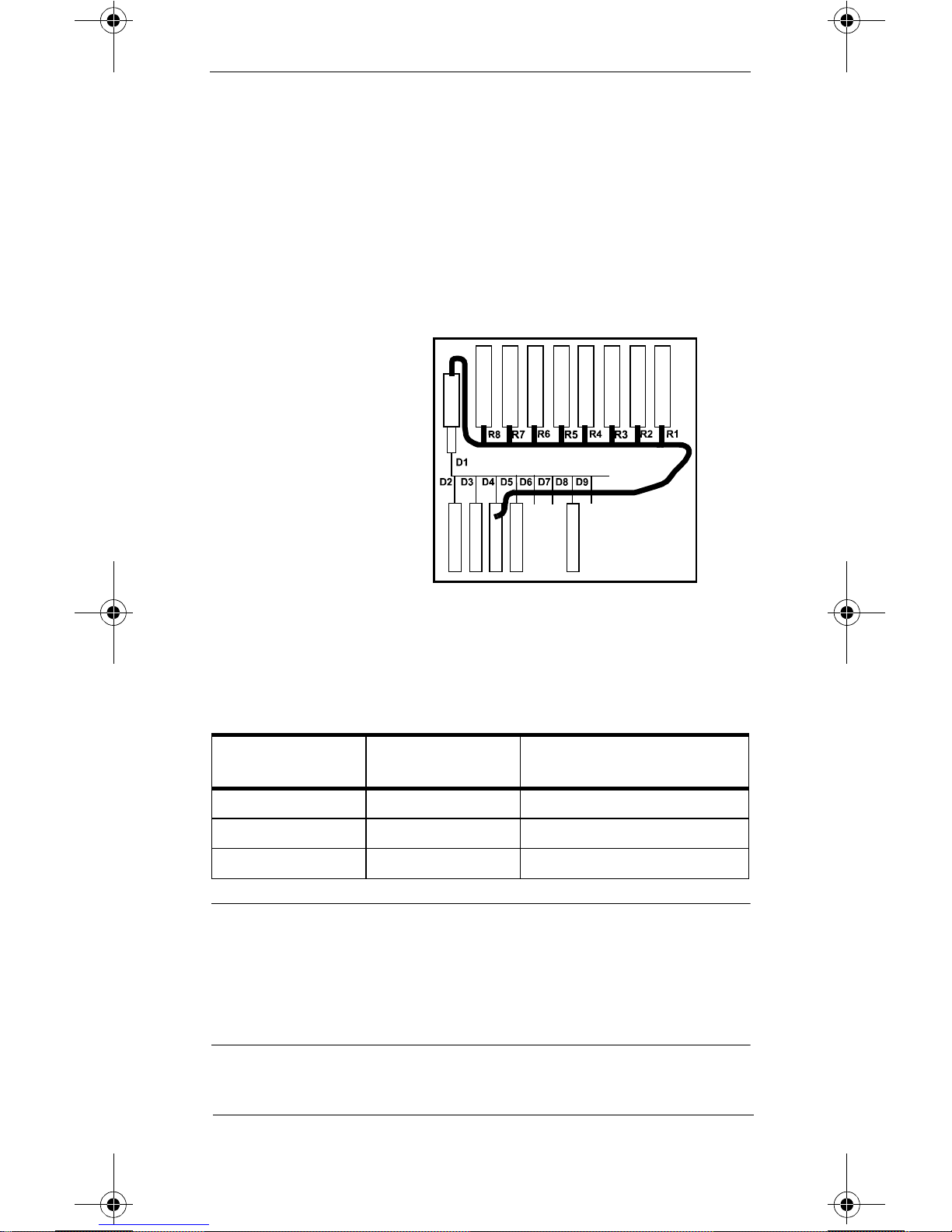
power. See
Figure 3 for the Receiver Mainframe
Board location.
Receiver Mainframe Board Location Diagram
R1-R8: Receiver Slots
D1: Rack Interface PCB
D2: Utility CPU PCB
D3: SDN Interface PCB
D4: Analog Output PCB
(optional)
D5: CPC PCB
D6: Unused
D7: Unused
D8: Power Supply PCB
Figure 3 Receiver Mainframe Board Location
Diagram
The LEDs should behave as follows:
Table 1. 40 MHz CPC Card
LED Step 1
(Normal Operation)
1 Red ON OFF
2 Green ON Slow Blink
3 Green ON Slow Blink
Step 2
Note
The 3 upper green LEDs on the Utility CPU are for the
power supply and should remain Green whene ver power
is applied to the receiver mainframe.
16
Receiver Mainframe/System Faults

If the normal bootstrap sequence occu rs, receiver
Table 2. Utility CPU Board
Step 4
LEDs Step 1 Step 2 Step 3
1 Green ON ON ON ON
2 GreenONONONON
3 GreenONONONON
(Normal
Operation)
4 Green ON FAST
BLINK
5 Green ON OFF ON OFF
6 Red ON OFF OFF OFF
FAST
BLINK
FAST
BLINK
mainframe hardware is probably working cor rectly. This
means th at the problem is elsewhere. Do the following to
help isolate where the problem lies.
1. Check the SDN cable t o see if it is miss i ng or
defective. If it is, replace or install a new one as
required.
2. Make certain there are not duplicate SDN beds. If
there are , reconfig ure the receiver mainframe for
other branch es or move one bedside to another
branch.
3. Make certain that two receiver mainframes do not
have identical SDN Unit numbers. If they do,
reconfigure one receiver mainframe with another
SDN unit number.
4. If it is a non-SCC system, an SDC cable may have
been used instead of an LDC cable. Check the cable
to make certain an LDC cable is being used.
5. The breakaway board portion of the SDN board
could be broken. Replace the SDN board.
Receiver Mainframe/System Faults
17

If an abno rmal bootstrap sequence occurs, then the
problem lies in the receiv er mainframe. To troubleshoot
the mainframe, do the following:
1. Remove power to the receiver mainframe and
remove the 40 MHz CPC Card. Re-apply power to
the receiver mainframe and observe the following
LED pattern on the Utility CPU du ring the
bootstrap routine:
Table 3. Utility CPU LED Pattern without CPC Board
Installed
LED Step 1 Step 2 Step 3
4 Green ON FAST BLINK FAST BLINK
5 Green ON OFF SLOW BLINK
6 Red ON OFF OFF
2. If the sequence in the table occurs, following is the
probable cause of the problem.
a. Refer to the
Compatibility Matrix Service Note
Philips Telemetry System
to verify the
compatibility between the Utility CPU and the
CPC PCB.
b. The 40 MHz CPC Card was in the wrong slot.
Check the correct card placement and insert
the CPC Card into the correct slot. The CPC
belongs in the 4th slot from the left in the rear
of the mainframe. See
Figure 3 on page 16.
c. The 40 MHz CPC Card is faulty. Replace it.
18
Receiver Mainframe/System Faults
 Loading...