

Philips FWC-38, FWC-39 Service manual

Mini System
FW-C38/21/21M/22/34/37
FW-C39/21/21M/30
Service
Service
Service
Service Manual
TABLE OF CONTENTS
Page
Location of pc boards & Version variations................1-2
Technical Specifications ............................................. 1-3
Measurement setup ....................................................1-4
Service Aids, Safety Instruction, etc...........................1-5
Instruction for use: Overseas version excerpt .......... 2-1
Additional features .................. 2-10
Disassembly Instructions & Service positions ...........3-1
Service Test Programs ............................................... 3-4
Set Block diagram ......................................................... 4
Set Wiring diagram ........................................................ 5
Front Board .................................................................... 6
Tuner Board: ECO5 Sys .......................................... 7B
Tuner 95............................................. 7D
ETF7 Tape Module ........................................................ 9
3CDC-99 Module .........................................................10
Combi Board ................................................................ 11
Set Mechanical Exploded view & parts list ................. 12
COMPACT
DIGITAL AUDIO
©
Copyright 2000 Philips Consumer Electronics B.V. Eindhoven, The Netherlands
All rights reserved. No part of this publication may be reproduced, stored in a retrieval system or
transmitted, in any form or by any means, electronic, mechanical, photocopying, or otherwise
without the prior permission of Philips.
Published by KC 0007 Service Audio Printed in The Netherlands Subject to modification
PCS 103 517
CLASS 1
LASER PRODUCT
GB
3139 785 22130
LOCATION OF PC BOARDS
1-2
CD KEY BOARD
MAINS
CD BOARD
BOARD
FRONT
BOARD
TUNER
KARAOKE
BOARD
ETF
BOARD
VERSION VARIATIONS:
Type /Versions: FW-C38 FW-C39
Features &
Board in used:
Dolby B
Incredible Surround xxxxxxxxx
Karaoke x x x x x
News x x
RDS x x
Rotary Encoder (volume control) xxxxxxxxx
Jog Shuttle xxxxxxxxx
Voltage Selector x x x x
Aux Input xxxxxxxxx
Digital Output xxxxxxxxx
Headphone Socket xxxxxxxxx
Line Output
Subwoofer Output xxxxxxxxx
Surround Output
Matrix Surround Loudspeakers x x x x
Tuner board - ECO5 Sys x x x xxxxx
Tuner board - Tuner 95 x
Standby with clock display xxxxxxxxx
/21 /21M /22 /34 /37 /21 /21M /30 /33
BOARD
H/P
BOARD
COMBI BOARD
PCS 103 518

SPECIFICATIONS
GENERAL:
Mains voltage : 110-127V/220-240V Switchable for /21/21M
120V for /37
220V for /33
220-230V for /22/34
230V for /25
230-240V for /30
Mains frequency : 50/60Hz
Power consumption Standby : < 25W
Active : < 75W
Clock accuracy : < 4 seconds per day
Dimension centre unit : 265 x 310 x 340mm
TUNER:
FM
Tuning range : 87.5-108MHz
65.81-74MHz for /34
1)
Grid : 50kHz (& 30kHz for /34)
100kHz for /37
IF frequency : 10.7MHz ± 25kHz
Aerial input : 75ohm coaxial
300ohm click fit for /37
Sensitivity at 26dB S/N : < 7µV
Selectivity at 600kHz bandwidth : > 25dB [> 30dB]
Image rejection : > 25dB [> 60dB]
Distortion at RF=1mV, dev. 75kHz : < 3%
-3dB Limiting point : < 8µV
Crosstalk at RF=1mV, dev. 40kHz : > 18dB
1-3
AMPLIFIER:
Output power
3)
2)
4)
@ 6 ohm
@ 6 ohm
@ 6 ohm /37
Left/Right : 2 x 25W FTC
2 x25W RMS
Surround : 2 x 5W
Frequency response within ±3dB : 50Hz-15kHz
Dynamic Bass Boost : DBB On, DBB Off
5)
Digital Sound Control : Jazz, Techno, Optimal, Rock
Incredible Surround : Inc Surr, IS Off
5)
VEC Control : Hall, Cinema, Concert
Input sensitivity
Aux-in : 700mV ± 3dB at 600ohm
Mic : {3.5mV ± 3dB} at 600ohm
Output sensitivity
Sub-woofer : 1.5V ± 3dB at 22kohm
Headphone : 18mW at 32ohm
Digital Out : 44.1kHz IEC958
CASSETTE RECORDER:
Number of track : 2 x 2 stereo
Tape speed : 4.76 cm/sec ± 2%
Wow and flutter : < 0.4% DIN
Fast-wind/rewind time C60 : 130 sec
Bias system : 75kHz ± 10kHz
Rec/Pb frequency response within 8dB : 80Hz - 12.5kHz
Signal to noise ratio Type I : > 48dBA
Type II : > 52dBA
5)
5)
MW
Tuning range : 531-1602kHz
530-1700kHz for /21/37
Grid : 9kHz
10kHz for /21/37
IF frequency : 450kHz ± 1kHz
Aerial input : Frame aerial
Sensitivity at 26dB S/N : < 4.0mV/M
Selectivity at 18kHz bandwidth : > 18dB
IF rejection : > 45dB [> 40dB]
Image rejection : > 28dB
Distortion at RF=50mV, m=80% : < 5%
LW
Tuning range : 153-279kHz
Grid : 3kHz
IF frequency : 450kHz ± 1kHz
Aerial input : Frame aerial
Sensitivity at 26dB S/N : [< 7.0mV/M]
Selectivity at 18kHz bandwidth : [> 30dB]
IF rejection : [> 25dB]
Image rejection : [> 35dB]
Distortion at RF=50mV, m=80% : [< 5%]
COMPACT DISC:
Measurement done at output conn. of the CDC module.
Frequency response within ± 1.5dB : 20Hz - 20kHz
Output level (in Vrms) : 550mV ± 2dB unloaded
Signal/Noise ratio (A-weighted) : > 80dBA
Distortion at 1kHz : < 0.003%
Channel difference at 1kHz : < ± 1dB
Channel separation at 1kHz : > 60dB
De-emphasis : 0 or 15/50 mS (Switched by subcode
on the disc)
[....] Values indicated are for "Tuner 95 Board" only
{....} Values indicated are for Karaoke version only
1)
Default setting is OFF, to switch on please refer to page 3-4
2)
±1dB, 60Hz - 12,5kHz, 10% THD
3)
±1dB, 1kHz, 10% THD
4)
For FW-C39 only
5)
Frequency response in each setting is software controlled.
PCS 103 519
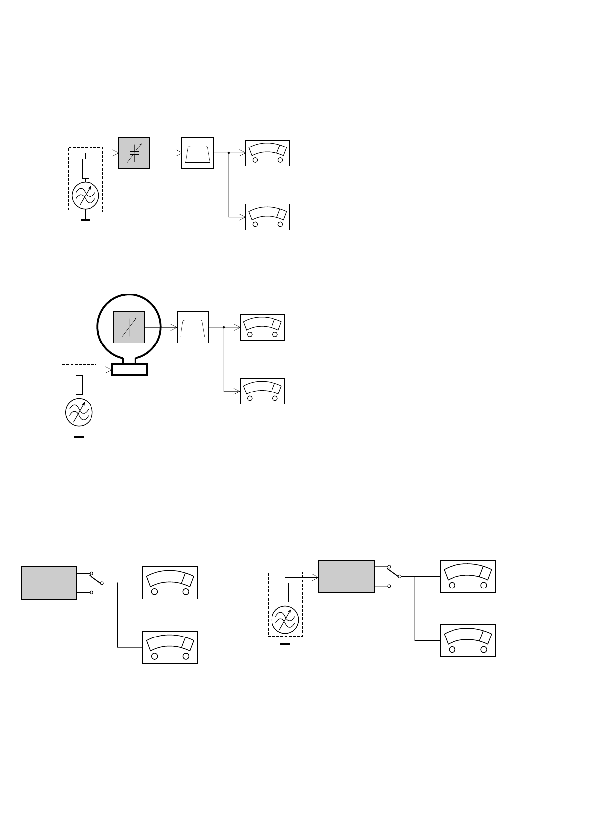
MEASUREMENT SETUP
Tuner FM
1-4
Bandpass
LF Voltmeter
e.g. PM2534
RF Generator
e.g. PM5326
DUT
250Hz-15kHz
e.g. 7122 707 48001
Ri=50Ω
S/N and distortion meter
e.g. Sound Technology ST1700B
Use a bandpass filter to eliminate hum (50Hz, 100Hz) and disturbance from the pilottone (19kHz, 38kHz).
Tuner AM (MW,LW)
RF Generator
e.g. PM5326
Ri=50Ω
DUT
Frame aerial
e.g. 7122 707 89001
Bandpass
250Hz-15kHz
e.g. 7122 707 48001
LF Voltmeter
e.g. PM2534
S/N and distortion meter
e.g. Sound Technology ST1700B
To avoid atmospheric interference all AM-measurements have to be carried out in a Faraday´s cage.
Use a bandpass filter (or at least a high pass filter with 250Hz) to eliminate hum (50Hz, 100Hz).
CD
Use Audio Signal Disc
(replaces test disc 3)
DUT
L
R
SBC429 4822 397 30184
S/N and distortion meter
e.g. Sound Technology ST1700B
LEVEL METER
e.g. Sennheiser UPM550
with FF-filter
Recorder
Use Universal Test Cassette CrO2 SBC419 4822 397 30069
or Universal Test Cassette Fe SBC420 4822 397 30071
LF Generator
e.g. PM5110
DUT
L
R
S/N and distortion meter
e.g. Sound Technology ST1700B
LEVEL METER
e.g. Sennheiser UPM550
with FF-filter
PCS 90 113
SERVICE AIDS
1-5
Service Tools:
Universal Torx driver holder .................................. 4822 395 91019
Torx bit T10 150mm ............................................. 4822 395 50456
Torx driver set T6 - T20 ......................................... 4822 395 50145
Torx driver T10 extended ...................................... 4822 395 50423
Cassette:
SBC419 Test cassette CrO2 ................................. 4822 397 30069
SBC420 Test cassette Fe ..................................... 4822 397 30071
MTT150 Dolby level 200nWb/M ............................ 4822 397 30271
Compact Disc:
SBC426/426A Test disc 5 + 5A ............................ 4822 397 30096
SBC442 Audio Burn-in Test disc 1kHz ................. 4822 397 30155
SBC429 Audio Signals disc .................................. 4822 397 30184
Dolby Pro-logic Test Disc ...................................... 4822 395 10216
ESD Equipment:
Anti-static table mat - large 1200x650x1.25mm ... 4822 466 10953
Anti-static table mat - small 600x650x1.25mm ..... 4822 466 10958
Anti-static wristband .............................................. 4822 395 10223
Connector box (1MΩ) ............................................ 4822 320 11307
Extension cable
(to connect wristband to conn. box) .................. 4822 320 11305
Connecting cable
(to connect table mat to conn. box) .................. 4822 320 11306
Earth cable (to connect product to mat or box) .... 4822 320 11308
Complete kit ESD3
(combining all above products) ......................... 4822 320 10671
Wristband tester .................................................... 4822 344 13999
PCS 90 114
WARNING
GB
All ICs and many other semi-conductors are
susceptible to electrostatic discharges (ESD).
Careless handling during repair can reduce life
drastically.
When repairing, make sure that you are
connected with the same potential as the mass
of the set via a wrist wrap with resistance.
Keep components and tools also at this
potential.
F
ATTENTION
Tous les IC et beaucoup d’autres
semi-conducteurs sont sensibles aux
décharges statiques (ESD).
Leur longévité pourrait être considérablement
écourtée par le fait qu’aucune précaution n’est
prise à leur manipulation.
Lors de réparations, s’assurer de bien être relié
au même potentiel que la masse de l’appareil et
enfiler le bracelet serti d’une résistance de
sécurité.
Veiller à ce que les composants ainsi que les
outils que l’on utilise soient également à ce
potentiel.
1-6
ESD
D
WARNUNG
Alle ICs und viele andere Halbleiter sind
empfindlich gegenüber elektrostatischen
Entladungen (ESD).
Unsorgfältige Behandlung im Reparaturfall kan
die Lebensdauer drastisch reduzieren.
Veranlassen Sie, dass Sie im Reparaturfall über
ein Pulsarmband mit Widerstand verbunden
sind mit dem gleichen Potential wie die Masse
des Gerätes.
Bauteile und Hilfsmittel auch auf dieses gleiche
Potential halten.
WAARSCHUWING
NL
Alle IC’s en vele andere halfgeleiders zijn
gevoelig voor electrostatische ontladingen
(ESD).
Onzorgvuldig behandelen tijdens reparatie kan
de levensduur drastisch doen verminderen.
Zorg ervoor dat u tijdens reparatie via een
polsband met weerstand verbonden bent met
hetzelfde potentiaal als de massa van het
apparaat.
Houd componenten en hulpmiddelen ook op
ditzelfde potentiaal.
I
AVVERTIMENTO
Tutti IC e parecchi semi-conduttori sono
sensibili alle scariche statiche (ESD).
La loro longevità potrebbe essere fortemente
ridatta in caso di non osservazione della più
grande cauzione alla loro manipolazione.
Durante le riparazioni occorre quindi essere
collegato allo stesso potenziale che quello della
massa dell’apparecchio tramite un braccialetto
a resistenza.
Assicurarsi che i componenti e anche gli utensili
con quali si lavora siano anche a questo
potenziale.
GB
Safety regulations require that the set be restored to its original
condition and that parts which are identical with those specified,
be used.
NL
Veiligheidsbepalingen vereisen, dat het apparaat bij reparatie in
zijn oorspronkelijke toestand wordt teruggebracht en dat onderdelen,
identiek aan de gespecificeerde, worden toegepast.
F
Les normes de sécurité exigent que l’appareil soit remis à l’état
d’origine et que soient utiliséés les piéces de rechange identiques
à celles spécifiées.
D
Bei jeder Reparatur sind die geltenden Sicherheitsvorschriften zu
beachten. Der Original zustand des Geräts darf nicht verändert werden;
für Reparaturen sind Original-Ersatzteile zu verwenden.
“Pour votre sécurité, ces documents
doivent être utilisés par des spécialistes agréés, seuls habilités à réparer
votre appareil en panne”.
CLASS 1
LASER PRODUCT
GB
Warning !
Invisible laser radiation when open.
Avoid direct exposure to beam.
S
Varning !
Osynlig laserstrålning när apparaten är öppnad och spärren
är urkopplad. Betrakta ej strålen.
3122 110 03420
I
Le norme di sicurezza esigono che l’apparecchio venga rimesso
nelle condizioni originali e che siano utilizzati i pezzi di ricambio
identici a quelli specificati.
"After servicing and before returning set to customer perform a
leakage current measurement test from all exposed metal parts to
earth ground to assure no shock hazard exist. The leakage current
must not exceed 0.5mA."
PCS 90 115
Varoitus !
SF
Avatussa laitteessa ja suojalukituksen ohitettaessa olet alttiina
näkymättömälle laserisäteilylle. Älä katso säteeseen!
DK Advarse !
Usynlig laserstråling ved åbning når sikkerhedsafbrydere er
ude af funktion. Undgå udsaettelse for stråling.
2-1
CONTENTS GENERAL INFORMATION SAFETY INFORMATION
General Information ................. 5
Safety Information .................... 5
Preparation .......................... 6 - 7
Controls ................................. 8 - 9
Operating The System .... 10 - 12
CD ....................................... 12 - 15
Tuner.................................. 16 - 17
Tape .................................... 17- 18
AUX ............................................18
Karaoke ..................................... 18
Recording ......................... 19 - 20
Clock ......................................... 20
Timer.......................................... 21
Sleep Timer ............................. 21
Specifications ......................... 22
Maintenance ............................ 23
Troubleshooting .............. 23 - 24
IMPORTANT:
PLEASE NOTE THAT THE
VOLTA GE SELECTOR
LOCATED AT THE REAR OF
THIS SYSTEM IS PRESET AT
220V FROM THE FACTORY.
FOR COUNTRIES THAT
OPERATE AT 110V, PLEASE
ADJUST TO 110V BEFORE YOU
SWITCH ON THE SYSTEM.
General Information
• The type plate (which contains the
serial number) is located at the rear
of the system.
• Recording is permissible if
copyright or other rights of third
parties are not infringed.
Environmental Information
All unnecessary packaging has been
omitted. We have tried to make the
packaging easy to separate into three
materials: cardboard (box), polystyrene
foam (buffer) and polyethylene (bags,
protective foam sheet).
Your system consists of materials which
can be recycled and reused if disassembled
by a specialized company. Please observe
the local regulations regarding the disposal
of packaging materials, exhausted
batteries and old equipment.
Accessories
(Supplied)
– Remote control
– Batteries (two AA size) for remote
control
– AM loop antenna
–FM wire antenna
– AC power cord
– SS-39 Surround Speakers
(for model FW-C39 only)
Safety Information
•Before operating the system, check that
the operating voltage indicated on the
typeplate (or the voltage indication
beside the voltage selector) of your
system is identical with the voltage of
your local power supply. If not, please
consult your dealer. The typeplate is
located at the rear of your system.
•When the system is switched on, do not
move it around.
• Place the system on a solid base (e.g. a
cabinet).
• Place the system in a location with
adequate ventilation to prevent internal
heat build-up in your system.
Allow at least 10cm clearance from the
rear and the top of the unit and 5cm
from each side.
• Do not expose the system to excessive
moisture, rain, sand or heat sources.
• Under no circumstances should you
repair the system yourself, as this will
invalidate the warranty!
• If the system is brought directly from a
cold to a warm location, or is placed in a
very damp room, moisture may
condense on the lens of the CD unit
inside the system. Should this occur, the
CD player will not operate normally.
Leave the power on for about one hour
with no disc in the system until normal
playback is possible.
•Electrostatic discharge may cause
unexpected problems. See whether
these problems disappear if you unplug
the AC power cord and plug it in again
after a few seconds.
•To disconnect the system from the
power supply completely, remove
the AC power plug from the wall
socket.
English
5
PREPARATION
English
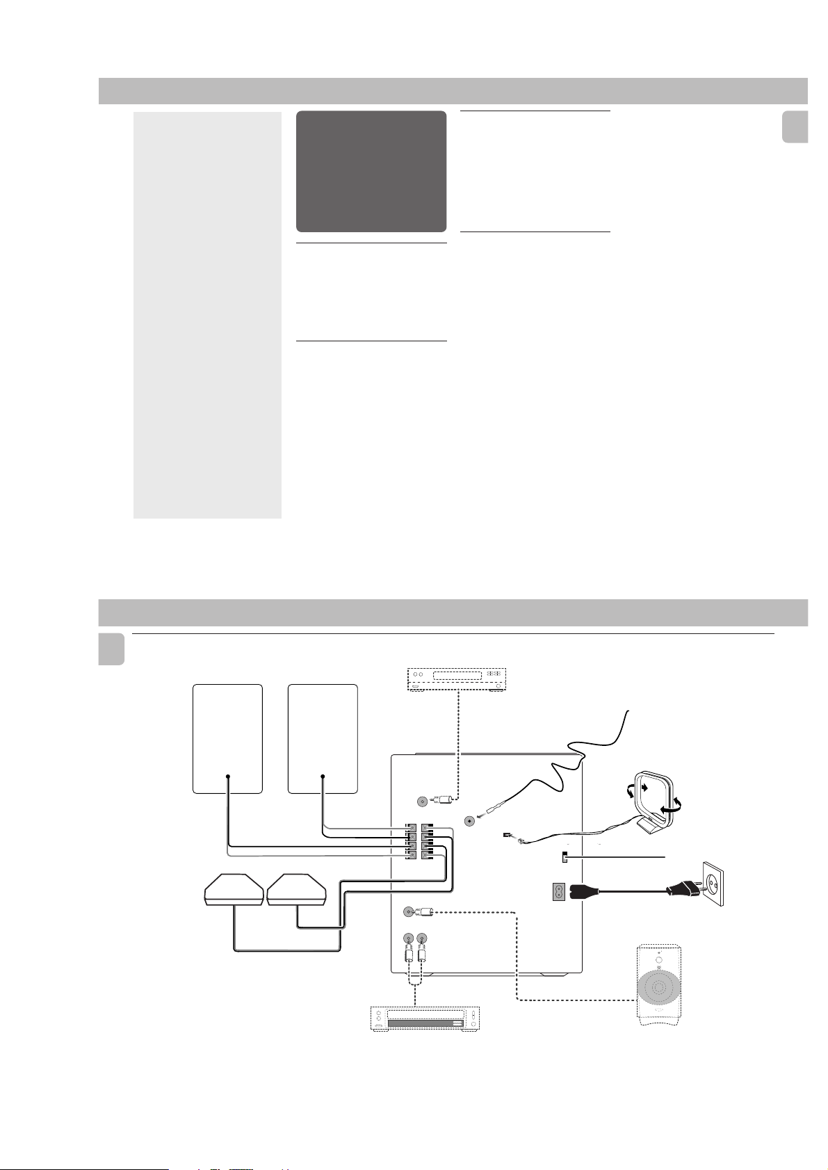
Rear Connections
E
D
L
L
surr.
(for model FWC39 only)
R
surr.
C
R
B
A
DIGITAL OUT
FM AERIAL
+
R
–
–
L
+
SUBWOOFER
OUT
75Ω
+
R
–
–
L
+
AM ANTENNA
MAINS
VOLTAGE
VOLTAGE
SELECTOR
SELECTOR
220V-
110V-
127V
240V
220V-
110V-
240V
127V
AC
~
H
I
AUX IN
STANDBY ON
V
E
L
E
R
L
E
C
F
O
O
N
O
T
W
R
O
B
L
U
S
MIN MAX
CUT OFF FREQUENCY
HIGH POWER SUBWOOFER
60Hz 150Hz
G
F
AUDIO OUT
6
PCS 103 520
A AM Loop Antenna
Connection
Connect the supplied loop antenna to the
AM ANTENNA terminal. Place the AM loop
antenna far away from the system and
adjust its position for the best reception.
B FM Wire Antenna
Connection
Connect the supplied FM wire antenna to
the FM AERIAL (FM ANTENNA) 75 Ω
terminal. Adjust the position of the FM
antenna for the best reception.
Outdoor Antenna
For better FM stereo reception, connect an
outdoor FM antenna to the FM AERIAL (FM
ANTENNA) 75 Ω terminal using a 75 Ω
coaxial wire.
FM AERIAL 75Ω
FM ANTENNA 75Ω
OR
C Digital Out Connection
You can record the digital sound from the
CD, through this output, on any audio
equipment with digital input (e.g. CD
Recorder, Digital Audio Tape (DAT) deck,
Digital to Analog Converter and Digital
Signal Processor).
Connect one end of the cinch cable (not
supplied) to the DIGITAL OUT socket and
the other end to the audio equipment with
digital input.When connecting the cinch
cable, make sure it is fully inserted.
D Speakers Connection
•Connect the right speaker to Front
terminal R, with the colored wire to +
and the black wire to -.
•Connect the left speaker to Front
terminal L, with the colored wire to +
and the black wire to -.
•Clip the stripped portion of the speaker
wire as shown.
12 mm
unlock lock
E Rear Surround Speakers'
Connection
only)
Connect the black (non-marked) wires to
the black REAR SURROUND terminals and
the colored (marked) wires to the grey
REAR SURROUND terminals.
(for models FW-C39
2-2
F Connecting other
equipment to your system
You can connect the audio left and right
OUT terminals of a TV, VCR, Laser Disc
player, DVD player or CD Recorder to the
AUX IN terminals at the rear of the system.
G Subwoofer Out Connection
Connect the optional active subwoofer to
the SUBWOOFER OUT terminal. The
subwoofer reproduces just the low bass
sound effect (e.g. explosions, the rumble of
spaceships, etc.). Be sure to follow the
instructions supplied with the subwoofer.
H Adjusting the Operating
Voltage
(not available for version /30)
Before connecting the AC power cord to
the wall outlet, make sure that the voltage
selector at the rear of the system is set to
the local power line voltage. If not, reset
the selector before connecting to the wall
outlet.
I AC Power Supply
After all other connections have been
made, connect the AC power cord to the
system and to the wall outlet.
PREPARATION
Inserting batteries into the
Remote Control
•Insert the batteries (Type R06 or AA)
into the remote control as shown in the
battery compartment.
+
-
+
-
•To avoid damage from possible battery
leakage, remove dead batteries or
batteries that will not be used for a long
time. For replacement, use type R06 or
AA batteries.
Notes for remote control:
–First select the source you wish to
control by pressing one of the
source select keys on the remote
control (e.g. CD ,TUNER, etc.).
– Then select the desired function
É,í,ë
(
, etc.).
English
7
CONTROLS
English
#
@
!
1
2
3
4
5
6
7
8
9
0
§
STANDBY-ON
C
E
V
C
S
▲
OPEN
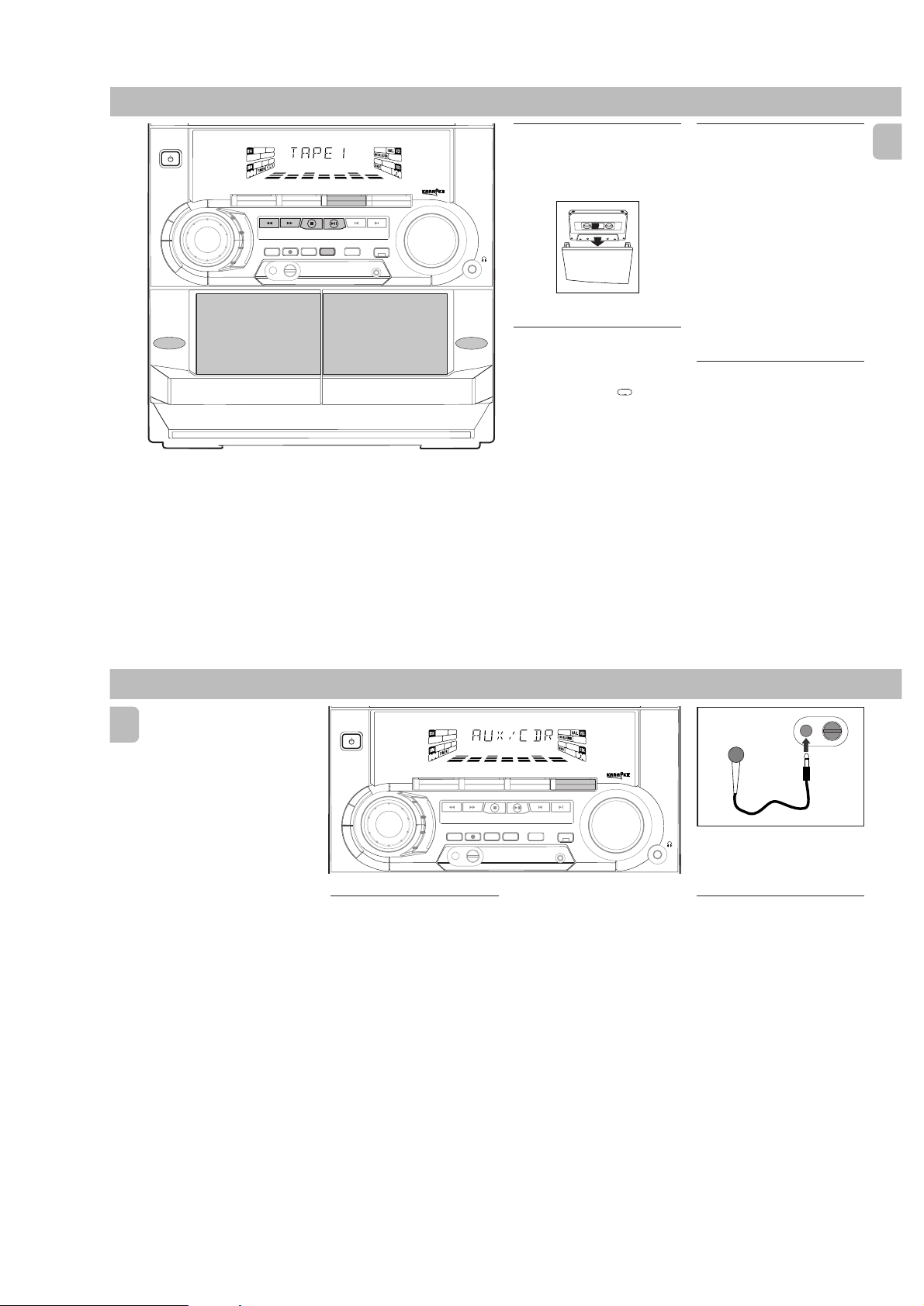
TAPE 1
OPEN
$
%
^
&
*
(
)
¡
▲
™
£
^
(
%
≥
*
&
&
5
REPEAT
í
à
DSC VEC
CD DIRECT
21
PAUSE
Å
VOLUME
É
Ç
DBB
ë
2
TUNERTAPE 1/2CD
SLEEPAUXINC.SURR.
SHUFFLE
á
º
ª
3
•
&
*
&
3
4
≤
DISC 2
DISC CHANGE
3
CHANGER
MINI HIFI SYSTEM
FW-
C10
JOG
CONTROL
B
B
D
D
DISC 1
DC
CD1 • 2 • 3 BAND
▲▲▲
TUNING
L
A
M
I
T
P
O
Z
Z
SEARCH
A
J
K
C
RECORD
PROGRAM DIM
O
R
O
MICROPHONE - LEVEL
N
H
C
E
T
▲
STOP•CLEAR
DUBBING A.REPLAY
DISC 3
TAPE 1 • 2
TAPECD TUNER
PLAY• PAUSE PREV NEXT
SOUND NAVIGATION - JOG
▲
PRESET
CLOCK•TIMER
INCREDIBLE
SURROUND
OPEN•CLOSE
3 CD ROTARY CHANGER SYSTEM
CD REWRITABLE COMPATIBLE
CD SYNCHRO RECORDING
CDR/VIDEO
AUX
▲
VOLUME
•
•
•
TAPE 2
∞
8
PCS 103 521
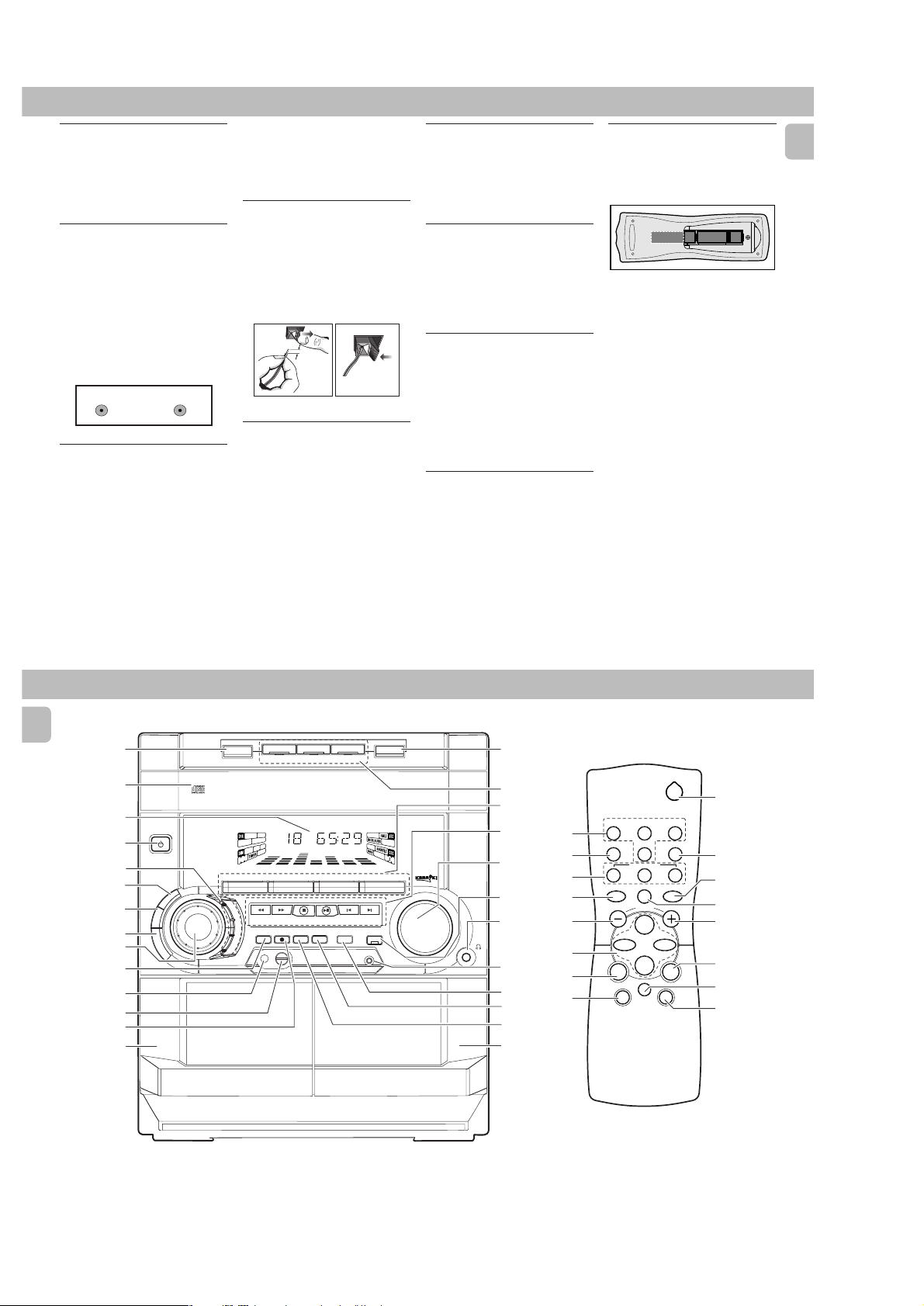
Controls on the system and
remote control
11
1 STANDBY ON
11
–to switch the system on or to standby
mode.
–to use for EASY SET.
22
2 DIGITAL SOUND CONTROL
22
DISPLAY PANEL
–to view the desired DSC display.
33
3 DBB (DYNAMIC BASS BOOST)
33
–to switch on bass boost, to enhance
bass response or to switch off bass
boost.
44
4 VEC
44
–to select the desired Virtual
Environment Control effect : HALL,
CINEMA or CONCERT.
55
5 DSC
55
–to select the desired sound effect :
OPTIMAL, JAZZ, ROCK or TECHNO.
66
6 JOG CONTROL
66
–to select the desired DSC setting. You
must select the DSC feature first.
–to select the desired VEC setting. You
must select the VEC feature first.
77
7 PROGRAM
77
for CD ............ to program CD tracks.
for TUNER ..... to program preset radio
for CLOCK ..... to select 12- or 24-
88
8 MICROPHONE
88
version /30)
–to connect microphones jack.
stations.
hour in clock setting
mode.
(not available for
99
9 MIC LEVEL
99
(not available for version
/30)
– to adjust the mixing level for karaoke
or microphone recording.
00
0 RECORD
00
– to start recording on tape deck 2 only.
!!
! DISPLAY SCREEN
!!
– to view the current setting of the
system.
@@
@ CD CAROUSEL TRAY
@@
##
# DISC CHANGE
##
– to change CD(s).
$$
$ OPEN•CLOSE
$$
– to open or close the CD carousel tray.
%%
% DISC 1 / DISC 2 / DISC 3 (CD
%%
DIRECT PLAY)
– to select a CD tray for playback.
^^
^ SOURCE – to select the following:
^^
CD / (CD 1•2•3)
– to select CD mode. When CD playback
is stopped, press to select disc tray 1,
2 or 3.
TUNER / (BAND)
– to select Tuner mode. When in tuner
mode, press to select the waveband:
FM or MW.
TAPE / (TAPE 1• 2)
– to select Tape mode. When tape
playback is stopped, press to select
either tape deck 1 or 2.
AUX (CDR/VIDEO)
– to select sound from an external
source (e.g. TV, VCR, Laser Disc player,
DVD player or CD Recorder).
2-3
&&
& MODE SELECTION
&&
SEARCH àá (TUNING àá)
for CD ............ to search backward/
for TUNER ...... to tune to a lower or
for TAPE ....... to rewind or fast
for CLOCK ..... to set the hour
STOP•CLEAR Ç
for CD ............ to stop CD playback or
for TUNER ..... to stop programming.
for TAPE ........ to stop playback or
for DEMO ......
PLAY É / PAUSE Å
for CD ............ to start or interrupt
for TAPE ........ to start playback.
PREV í / NEXT ë(PRESET 43 )
for CD ............ to skip to the beginning
for TUNER ..... to select a preset
for CLOCK ..... to set the minute
**
* VOLUME
**
– to increase or decrease the volume.
forward.
higher radio frequency.
forward on tape.
system only)
to clear a program.
recording.
(on the system only)
start or stop
demonstration mode.
playback.
of the current, previous,
or next track.
station in memory.
the system only).
.
(on the
(on
CONTROLS
((
( INCREDIBLE SURROUND
((
–to switch on or off the surround sound
effect.
))
) n
))
–to connect headphones.
¡¡
¡ CLOCK•TIMER
¡¡
–to view the clock, set the clock or set
the timer.
™™
™ DIM
™™
–to select different brightness for the
display screen : DIM 1, DIM 2, DIM 3
or DIM OFF.
££
£ AUTO REPLAY
££
–to select playback mode either in
continuous AUTO REPLAY or ONCE
only.
≤≤
≤ DUBBING
to
≤≤
–to dub a tape in normal speed.
∞∞
∞ TAPE DECK 2
∞∞
§§
§ TAPE DECK 1
§§
≥≥
≥ REPEAT
≥≥
–to repeat a CD track, a disc, or all
available discs.
••
• SHUFFLE
••
–to play all the available discs and their
tracks in random order.
ªª
ª SLEEP
ªª
–to switch the system to standby mode
at a selected time.
ºº
º B
ºº
–to switch the system to standby mode.
English
9
OPERATING THE SYSTEM
English
STANDBY-ON
B
D
C
E
V
C
S
D
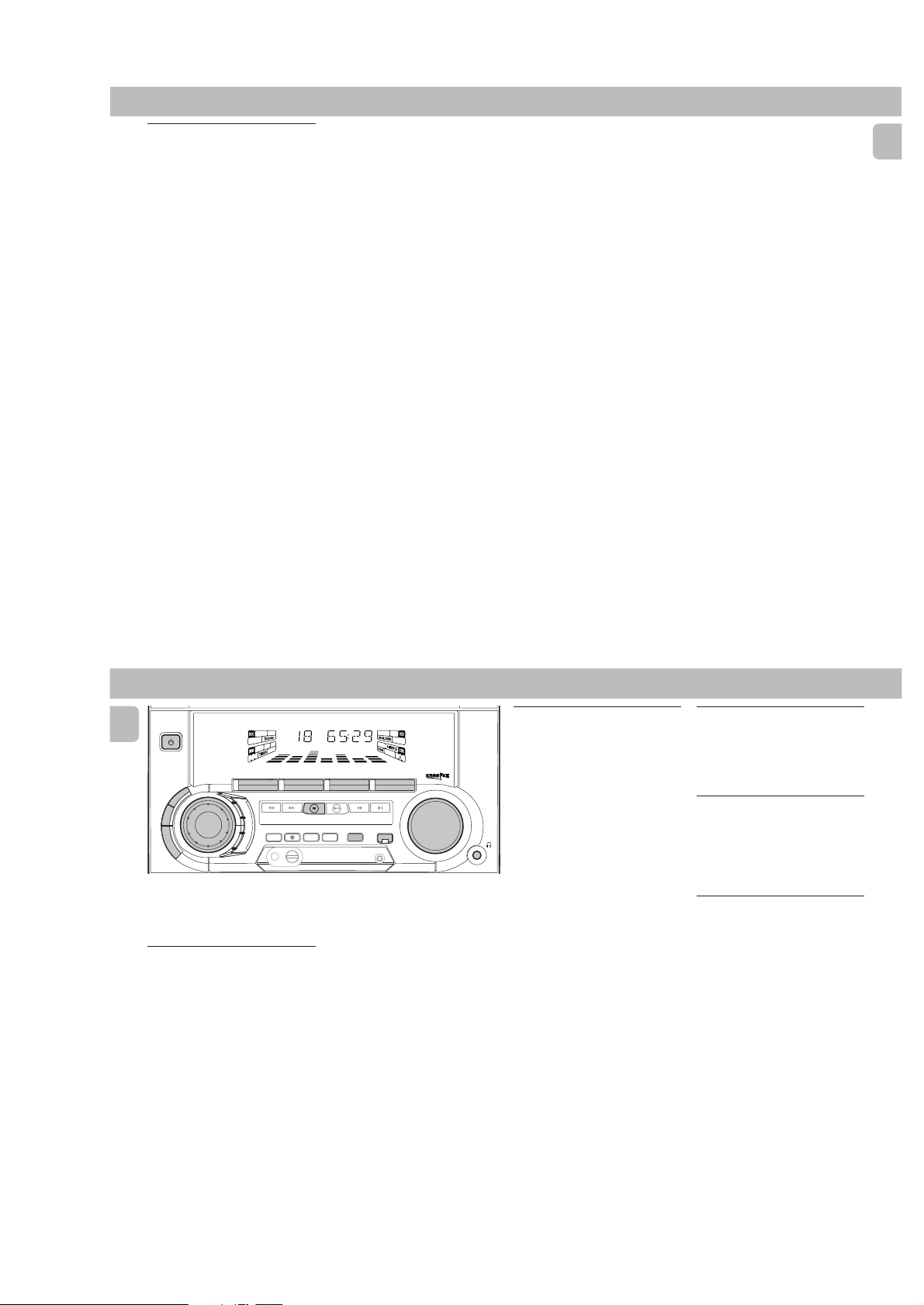
Important:
Before you operate the system,
complete the preparation procedures.
Demonstration mode
The system has a demonstration mode that
shows the various features offered by the
When the system is switched
system.
on for the first time, the demonstration
mode will start automatically.
Notes:
–During the demonstration, if you press
any source (or standby-on) button, the
system will switch to the respective
mode (or standby).
– When the system is switched to standby
mode, the demonstration will resume 5
seconds later.
10
MINI HIFI SYSTEM
FW-
C10
JOG
CONTROL
B
CD1 • 2 • 3 BAND
L
A
M
I
T
P
O
Z
Z
A
J
K
C
O
R
O
N
H
C
E
T
TAPE 1 • 2
PLAY• PAUSE PREV NEXT
STOP•CLEAR
DUBBING A.REPLAY
SOUND NAVIGATION - JOG
TAPECD TUNER
▲▲▲
▲
TUNING
SEARCH
RECORD
PROGRAM DIM
To stop the demonstration mode
•Press and hold Ç
for
demonstration mode.
™ The demonstration will stop.
™ "DEMO OFF" is displayed.
™ The system will switch to standby
Note:
–Even though the AC power cord is
removed from and reconnected to the
wall socket, the demonstration will
remain off until it is switched on again.
To start the demonstration mode
•Press and hold Ç
for
standby mode.
™ The demonstration will begin.
CDR/VIDEO
▲
▲
PRESET
INCREDIBLE
SURROUND
CLOCK•TIMER
5 seconds
mode.
5 seconds
AUX
VOLUME
(on the system only)
when the system is in
(on the system only)
when the system is in
Easy Set
EASY SET allows you to store all available
radio stations automatically.
• Press and hold STANDBY ON
for
system only)
5 seconds
system is in standby or demonstration
mode.
™ “EASY SET” will be displayed, and
followed by “TUNER” and then
“AUTO”.
™ EASY SET will start searching for all
radio on FM band and then followed
by radio stations on MW band.
™ All available radio stations with
sufficient signal strength will be
stored. Up to 40 presets may be
stored.
Notes:
– EASY SET will start with the FM band, if
there are still presets available, the
system will continue to store the MW
band.
– When EASY SET is used, all previously
stored radio stations will be replaced.
–The last preset radio station will appear
on the display when EASY SET is
completed.
(on the
when the
Switching the system ON
•Press CD, TUNER, TAPE or AUX.
You can also switch on the system by
pressing any one of the CD DIRECT PLAY
buttons.
Switching the system to
standby mode
•Press STANDBY ON or B on the
remote control.
™ The system will switch to standby
mode.
Selecting the Source
•Press the respective source selection
button: CD, TUNER, TAPE or AUX.
™ The display indicates the selected
source.
Note:
– For an external source, make sure you
have connected the audio left and right
OUT terminals of the external
equipment (TV, VCR, Laser Disc player,
DVD player or CD Recorder) to the AUX
IN terminals.
PCS 103 522
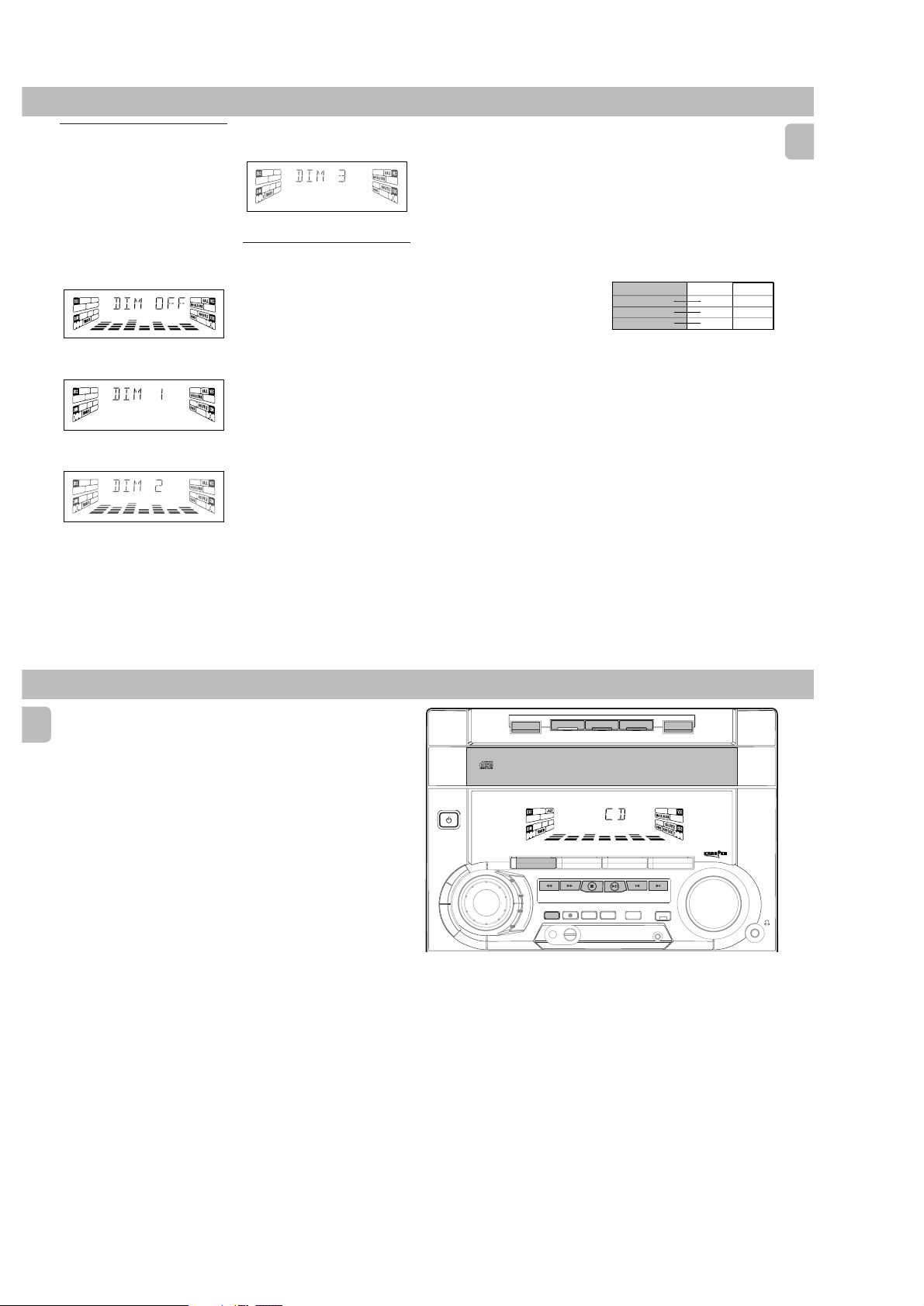
DIM mode
3CDROTARYCHANGERSYSTEM
CDREWRITABLE COMPATIBLE
CDSYNCHRO RECORDING
You can select the desired brightness for
the display.
•Press DIM to select DIM 1, DIM 2, DIM
3 or DIM OFF display mode.
™ The
DIM appear on the display.
™ "DIM 1", "DIM 2", "DIM 3" or
"DIM OFF" will be displayed
depending on the mode selected.
DIM OFF - normal brightness with
Spectrum Analyzer On
DIM 1 - normal brightness with
Spectrum Analyzer Off
DIM 2 - half brightness with Spectrum
Analyzer On
DIM 3 - half brightness with Spectrum
Analyzer Off and all LEDs on the
system will be switched off.
Sound Control
VOLUME ADJUSTMENT
Adjust VOLUME to increase or decrease
the sound level.
For Personal Listening
Connect the headphones plug to the n
socket at the front of the system. The
speakers will be muted.
DIGITAL SOUND CONTROL (DSC)
The DSC feature enables you to enjoy
special sound effects that have preset
equalizer settings, providing the best music
reproduction.
1 Press to select the DSC feature.
2 Adjust JOG CONTROL to select
OPTIMAL, JAZZ, ROCK or TECHNO.
™ The Digital Sound Control display
panel will light up respectively.
™ “OPTIMAL, JAZZ, ROCK or
TECHNO” and the respective flag
will be displayed.
2-4
Note:
– When ”OPTIMAL” sound is selected,
DBB will be switched on automatically.
DYNAMIC BASS BOOST (DBB)
The DBB mode enhances the bass
response.
•Press DBB to switch on bass response.
™ The DBB button lights up.
™ “DBB ON” and the DBB flag will be
displayed.
To switch off DBB
•Press DBB again.
™ The DBB button light is switched off.
™ “DBB OFF” will be displayed.
™ The DBB flag disappear from the
display.
Note:
– Some CDs or tapes might be recorded in
high modulation, which causes a
distortion at high volume. If this occurs,
switch off DBB or reduce the volume.
OPERATING THE SYSTEM
VIRTUAL ENVIRONMENT CONTROL
(VEC)
The VEC feature enables you to adjust the
system to select a type of environment.
1 Press to select the VEC feature.
2 Adjust the JOG CONTROL to select the
desired Virtual Environment Control
setting : HALL, CINEMA or CONCERT.
™ "HALL, CINEMA or CONCERT"
and the respective flag will be
displayed.
IS
VEC Selection
HALL
CONCERT
CINEMA
DBB
On
Off
Off
On
On
On
English
OPERATING THE SYSTEM CD
English
Incredible Surround
Normal stereo sound is determined by the
distance between the front speakers.
When Incredible Surround is switched on,
it magnifies the virtual distance between
the front speakers for an incredibly wide,
enveloping, stereo effect.
•Press INCREDIBLE SURROUND to
switch on.
™ The INCREDIBLE SURROUND button
lights up.
™ “INC SURR” and the INCR. SURR
flag will be displayed.
To switch off Incredible Surround
•Press INCREDIBLE SURROUND again.
™ The INCREDIBLE SURROUND button
light is switched off.
™ “IS OFF” will be displayed.
™ The INCR. SURR flag disappear
from the display.
DISC 2
DISC 3
TAPE 1 • 2
TAPECD TUNER
PLAY• PAUSE PREV NEXT
SOUND NAVIGATION - JOG
▲
PRESET
INCREDIBLE
SURROUND
CLOCK•TIMER
OPEN•CLOSE
3 CD ROTARY CHANGER SYSTEM
CD REWRITABLE COMPATIBLE
CD SYNCHRO RECORDING
CDR/VIDEO
AUX
▲
VOLUME
•
•
•
STANDBY-ON
C
E
V
C
S
DISC CHANGE
3
CHANGER
MINI HIFI SYSTEM
FW-
C10
JOG
CONTROL
B
B
D
D
DISC 1
DC
CD1 • 2 • 3 BAND
▲▲▲
TUNING
L
A
M
I
T
P
O
Z
Z
SEARCH
A
J
K
C
RECORD
PROGRAM DIM
O
R
O
N
H
C
E
T
▲
STOP•CLEAR
DUBBING A.REPLAY
Warning!
1) This system is designed for conventional CDs. Do not use any accessories
such as disc stabilizer rings or CD treatment sheets, etc., which may damage
the CD mechanism.
2) Do not load more than one disc into each tray.
3) When the CD changer is loaded with CDs, do not turn over or shake the
system. This may jam the changer.
You may load three discs in the CD changer for continuous playback without
interruption.
11
12
PCS 103 523

Discs for playback
This system can play all digital audio CD,
finalized digital audio CD-Recordable and
finalized digital audio CD-Rewritable
format discs.
Loading the CD Changer
1 Press CD to select CD mode.
2 Press OPEN•CLOSE.
™ The CD carousel tray slides out.
3 Load a CD with the printed side up in
the right tray.
•You can load another disc in the left
tray.
•To load the third disc, press the DISC
CHANGE button.
™ The CD carousel tray will rotate until
the empty tray is ready for loading.
4 Press OPEN•CLOSE to close the CD
carousel tray.
™ The total number of tracks and the
playing time of the selected disc
appear on the display.
Note:
–To ensure good system performance,
wait until the CD changer completely
reads the disc(s) before proceeding.
CD Direct Play
•You can play a CD directly by pressing
the DISC 1, DISC 2 or DISC 3 button.
The CD player will stop at the end of
playback of the selected disc.
™ A lit button indicates that a disc is
loaded in the disc tray.
™ A flashing button indicates that a
disc is playing.
Playing a CD
1 PressÉ to start playback.
™ The disc tray, track number and
elapsed playing time of the current
track appear on the display.
•To interrupt playback, pressÅ.
™ The playing time flashes.
•To resume playback, pressÉ again.
2 To stop playback, press Ç.
Note:
–All the available discs will play once,
then stop.
2-5
Disc Change
You can change the outer two discs while
the third inner disc is stopped or is playing.
1 Press DISC CHANGE.
™ The CD carousel tray slides out.
2 Replace the discs in the left and right
disc trays.
• If you press DISC CHANGE again
during playback, the CD will stop
playing.
™ The CD carousel tray will rotate until
the inner tray is rotated out and is
ready for changing.
3 Press OPEN•CLOSE to close the CD
carousel tray.
Selecting a desired track
Selecting a desired track when
playback is stopped
1 Press í or ë until the desired track
appears on the display.
2 PressÉ to start playback.
™ The selected track number and
elapsed playing time appear on the
display.
CD
Selecting a desired track during
playback
•Press í or ë until the desired track
appears on the display.
™ The selected track number and
elapsed playing time appear on the
display.
• If you press í once it will skip to the
beginning of the current track and play
the track again.
Note:
–Pressingí during shuffling can only
skip to the beginning of the current
track.
Searching for a particular
passage during playback
•Press and hold à or á until the
desired passage is located.
™ The volume will be reduced.
•Play returns to normal when à or á
is released.
English
CD
English
Programming Tracks
Programming tracks of a loaded CD is
possible when playback is stopped. The
display will indicate the total tracks stored
in the program. Up to 40 tracks can be
stored in the memory in any order. When
40 tracks are stored and you attempt to
store another track, the display will show
“PROGRAM FULL”.
1 Load the desired discs in the disc trays.
2 Press PROGRAM to start programming.
™ The PROG flag starts flashing.
™ It will cancel any previously selected
repeat mode.
3 Press the CD (CD 1•2•3) or DISC 1/2/3
button to select the disc.
4 Pressí or ë to select the desired
track.
5 Press PROGRAM to store the track.
• Repeat steps
and tracks.
6 Press Ç once to end programming.
™ The total number of tracks
Notes:
– If the total playing time is more than
99:59
“
tracks has a number greater than 30,
then “
instead of the total playing time.
3
to 5 to store other discs
programmed and total playing time
appear on the display.
“
or if one of the programmed
--:--
” appears on the display
– If the system is reading the discs,
programming is not possible,
“
READING
” will be displayed and
DISC X
followed by ”
current read disc number.
– During programming, if no button is
pressed within 20 seconds, the system
will exit program mode automatically.
”. ”X” is the
Reviewing the program
Reviewing of the program is possible only
when playback is stopped.
•Pressí or ë repeatedly to review the
programmed tracks.
•Press Ç to exit review mode.
Playing the program
1 Press É to start program playback.
™ “PLAY PROGRAM” will be
displayed.
™ The track number and elapsed
playing time of the current track will
appear on the display.
• If you press REPEAT during program
playback, the current track or all
programmed tracks will be played
repeatedly.
™ “TRACK” or "PROGRAM" will be
displayed.
™ The REPEAT and PROG flags appear
on the display.
2 Press Ç to stop program playback.
Notes:
– If you press any of the CD DIRECT PLAY
buttons, the system will play the
selected disc or track and the stored
program will be ignored temporarily. The
PROG display also will disappear
temporarily from the display. It will
reappear when playback of the selected
disc ends.
– REPEAT DISC mode will be cancelled
when program playback begins.
Erasing the program
playback is stopped)
• Press Ç.
™ “PROGRAM CLEARED” will be
displayed.
Note:
– The program will be erased when the
system is disconnected from the power
supply or when the CD carousel tray is
opened.
(when
Shuffle
(only on remote control)
In shuffle mode, the system plays all the
available discs and their tracks in random
order. Shuffle may be used also when
tracks are programmed.
To shuffle all the discs and tracks
1 Press SHUFFLE.
™ “SHUFFLE” will be displayed.
™ The SHUFFLE flag, the disc and the
track selected at random appear on
the display.
• The discs and the tracks will be played
in random order until you pressÇ.
• If you press REPEAT during shuffling,
the current track or all available discs
will be played repeatedly.
™ “TRACK” or “ALL DISC” will be
displayed.
™ The REPEAT and SHUFFLE flags
appear on the display.
2 Press SHUFFLE again to resume normal
playback.
™ The SHUFFLE flag disappears from
the display.
Note:
– REPEAT DISC mode will be cancelled
when shuffle is selected.
13
14
PCS 103 524

2-6
CD TUNER
Repeat
(only on remote control)
You can play the current track, a disc or all
available discs repeatedly.
1 Press REPEAT on the remote control to
select the various repeat modes.
™ “TRACK”, “DISC”, “ALL DISC”
or “OFF” will be displayed.
™ The REPEAT flag appears on the
display.
• The selected track, selected disc or all
available discs will now be played
repeatedly until you pressÇ.
2 Press REPEAT until the "OFF" mode is
displayed to resume normal playback.
™ The REPEAT flag disappears from
the display.
Notes:
– REPEAT DISC mode is not available
during program play or shuffle mode.
–You can also repeat shuffling a program.
™ “
TRACK
“
or
“
PROGRAM
"
will be
displayed.
The REPEAT, PROG, and SHUFFLE
™
flags appear on the display.
STANDBY-ON
B
B
D
C
E
V
C
S
D
Note:
–For 'EASY SET' feature, please refer to
page 10.
Tuning to radio stations
1 Press TUNER (BAND) to select TUNER
mode.
™ “TUNER” will be displayed.
A few seconds later, the current radio
frequency will be displayed.
2 Press TUNER (BAND) again to select
the desired waveband : FM or MW.
3 Press à or á for more than one
second, then release.
™ The display will show “SEARCH”
until a radio station with sufficient
signal strength is found.
• Repeat this procedure until the desired
station is reached.
FW-
JOG
CONTROL
C10
MINI HIFI SYSTEM
CD1 • 2 • 3 BAND
L
A
M
I
T
P
O
Z
Z
A
J
K
C
PROGRAM DIM
O
R
O
N
H
C
E
T
▲▲▲
TUNING
SEARCH
RECORD
▲
STOP•CLEAR
DUBBING A.REPLAY
TAPE 1 • 2
CDR/VIDEO
TAPECD TUNER
PLAY• PAUSE PREV NEXT
SOUND NAVIGATION - JOG
▲
PRESET
CLOCK•TIMER
▲
INCREDIBLE
SURROUND
AUX
VOLUME
•To tune to a weak station, briefly press
à or á repeatedly until the display
shows the desired frequency and/or
when the best reception has been
obtained.
Storing Preset Stations
You can store up to 40 radio stations in the
memory. When a preset radio station is
selected, the preset number appears next
to the frequency on the display.
English
15
TUNER
English
Automatic programming
1 Press TUNER (BAND).
2 Press PROGRAM for more than one
second.
™ The PROG flag starts flashing and
“AUTO” will be displayed.
™ The system will search for every
available station in the FM waveband
first, then search the MW waveband.
™ All available stations will be stored
automatically. The frequency and
preset number will be displayed
briefly.
™ The system will stop searching when
all the available radio stations are
stored or when the memory for 40
preset radio stations is used.
™ The system will remain tuned to the
last stored preset radio station.
Notes:
–You can cancel the automatic
programming by pressing PROGRAM or
Ç
(on the system only).
– If you want to reserve a section of
preset numbers, for example preset
numbers 1 to 9, select preset 10 before
starting automatic programming, only
the preset numbers 10 to 40 will be
programmed.
Manual programming
1 Press TUNER (BAND).
2 Press TUNER (BAND) again to select
the desired waveband : FM or MW.
3 Press PROGRAM for less than one
second.
™ The PROG flag starts flashing.
™ The next available preset number will
be displayed for selection.
4 Press à or á to tune to the desired
frequency.
• If you wish to store the radio station to
another preset number, press 4 or 3 to
select the desired preset number.
5 Press PROGRAM again.
™ The PROG flag disappears and the
radio station will be stored.
steps 3 – 5
•Repeat
to store other preset
radio stations.
Notes:
–When 40 radio stations are stored and
you attempt to store another radio
station, the display will show
PROGRAM FULL
"
”. If you want to
change an existing preset number,
repeat steps 3 – 5.
–You can cancel manual programming by
Ç
pressing
(on the system only).
– During programming, if no button is
pressed within 20 seconds, the system
will exit program mode automatically.
Tuning to Preset Radio
Stations
•Press 4 or 3 to select the desired
preset number.
™ The preset number, radio frequency,
and waveband appear on the display.
Changing the MW tuning grid
(not available for version /30)
The frequency step can be changed if
necessary. In North and South America, the
frequency step between adjacent channels
in the MW band is 10 kHz. In other parts of
the world, it is 9 kHz. The frequency step
preset in the factory is 9 KHz.
For MW Band
To change from 9 kHz to 10 kHz or vice
versa
Changing of tuning grid will erase all
previously stored preset stations.
1 Disconnect the system from the AC
power supply
cord)
2 Press and hold TUNER and TUNING
á while reconnecting the system to
the AC power supply.
™ Display will show “GRID 10” or
(pull out the AC power
.
“GRID 9”.
Notes:
– GRID 9 indicates that the tuning grid is
in step of 9 kHz in MW band. GRID 10
indicates that the tuning grid is in step
of 10 kHz in MW band.
–FM tuning grid will also be changed
from 50 kHz to 100 kHz or vice versa. All
preset stations will also be erased.
16
PCS 103 525
2-7
MICROPHONE - LEVEL
TAPE
STANDBY-ON
C
E
V
C
S
▲
OPEN
TAPE 1
MINI HIFI SYSTEM
FW-
C10
Loading a tape
1 Press OPEN.
2 The tape deck door opens.
3 Load the tape with the open side
JOG
CD1 • 2 • 3 BAND
CONTROL
B
B
D
D
▲▲▲
TUNING
L
A
M
I
T
P
O
Z
Z
SEARCH
A
J
K
C
RECORD
PROGRAM DIM
O
R
O
N
H
C
E
T
▲
STOP•CLEAR
DUBBING A.REPLAY
SOUND NAVIGATION - JOG
TAPE 1 • 2
TAPECD TUNER
▲
PRESET
PLAY• PAUSE PREV NEXT
INCREDIBLE
CLOCK•TIMER
▲
SURROUND
CDR/VIDEO
AUX
VOLUME
▲
OPEN
PLAYBACK
TAPE 2
downward and the full spool to the left.
4 Close the tape deck door.
Auto Replay
• Press A. REPLAY to select either
continuous AUTO REPLAY or ONCE
during tape playback.
™ "AUTO REPLAY "(
) or "ONCE
"(È) will be displayed.
Notes:
– This feature is available during tape
playback only.
–When "
AUTO REPLAY
" is selected,
the tape will rewind automatically at
the end of playback for the selected
side. Then it will start playing again. It
will replay up to a maximum of 20 times
Ç
until you press
– When "
.
ONCE
" is selected, the tape will
play the selected side once and then
stop.
Tape Playback
1 Press TAPE (TAPE 1•2) to select TAPE
mode.
™ "TAPE 1" or "TAPE 2" will be
displayed and followed by "T1
222 " or "T2 222".
2 Load the tape into the selected tape
deck.
3 Press É to start playback.
™ "T1" or "T2" with "2" scrolling right
will be displayed.
•Press A.REPLAY to select the different
type of playback mode
(see Auto
Replay).
4 Press Ç to end playback.
™ "T1" or "T2" with "222" will be
displayed.
Rewind/Fast Forward
When playback is stopped
1 You can rewind or fast forward the tape
by pressing à or á respectively.
™ If rewinding, "T1
“1” scrolling left will be displayed.
™ If fast forwarding, "T1
T2
2" with “2” scrolling right will
be displayed.
™ The tape will stop automatically at
the end of rewinding or fast
forwarding.
2 Press Ç to stop rewinding or fast
forwarding.
1 or T2
2 or
1" with
English
17
TAPE AUX KARAOKE
English
During playback
•Press and hold à or á until the
desired passage is located.
™ “T1 or T2” with “11 or 22”"
scrolling left or right will be
displayed depending on which button
is pressed.
™ During searching, the sound is
reduced to a low volume.
™ When you release à or á, the
tape continues playing.
Notes:
– During rewinding or fast forwarding of a
tape, it is also possible to select another
source (e.g. CD, TUNER, or AUX).
–Before playing a tape, check and tighten
slack tape with a pencil. Slack tape may
get jammed or may burst in the
mechanism.
–C-120 tape is extremely thin and is
easily deformed or damaged. It is not
recommended for use in this system.
–Store the tapes at room temperature
and do not put them too close to a
magnetic field (for example, a
transformer, TV, or speaker).
.
18
STANDBY-ON
B
D
C
E
V
C
S
D
Selecting External Equipment
If you have connected the audio out
terminals of the external equipment (TV,
VCR, Laser Disc player, DVD player or CD
Recorder) to the AUX IN terminals, you can
hear the enhanced sound from the system.
•Press AUX (CDR/VIDEO) to select the
external equipment.
™ "AUX1 CDR" will be displayed.
Note:
–All the sound control features (e.g. DSC,
DBB, etc.) are available for selection.
MINI HIFI SYSTEM
FW-
C10
JOG
CONTROL
B
CD1 • 2 • 3 BAND
▲▲▲
TUNING
L
A
M
I
T
P
O
Z
Z
SEARCH
A
J
K
C
RECORD
PROGRAM DIM
O
R
O
N
H
C
E
T
▲
PLAY• PAUSE PREV NEXT
STOP•CLEAR
DUBBING A.REPLAY
SOUND NAVIGATION - JOG
TAPE 1 • 2
TAPECD TUNER
▲
PRESET
CLOCK•TIMER
CDR/VIDEO
▲
INCREDIBLE
SURROUND
AUX
VOLUME
Microphone Mixing
for version /30)
1 Set the MIC LEVEL control to the
minimum level to prevent acoustic
feedback (e.g. a loud howling sound)
before you connect the microphone.
2 Connect a microphone to the
MICROPHONE socket.
3 Press CD, TUNER, TAPE or AUX.
4 Play the selected source.
5 Adjust the volume level with VOLUME
control.
6 Adjust the MIC LEVEL control to the
mixing level that you want.
7 Start singing or talking through the
microphone.
Note:
– Keep the mic away from the speakers to
prevent howling
(not available
PCS 103 526
STANDBY-ON
C
E
V
C
▲
OPEN
TAPE 1
2-8
RECORDING
MINI HIFI SYSTEM
FW-
C10
Notes:
– If you do not intend to record via the
microphone, unplug the microphone to
avoid accidental mixing with other
JOG
CD1 • 2 • 3 BAND
CONTROL
B
B
D
S
D
▲▲▲
TUNING
L
A
M
I
T
P
O
Z
Z
SEARCH
A
J
K
C
RECORD
PROGRAM DIM
O
R
O
N
H
C
E
T
▲
PLAY• PAUSE PREV NEXT
STOP•CLEAR
DUBBING A.REPLAY
SOUND NAVIGATION - JOG
TAPE 1 • 2
TAPECD TUNER
▲
PRESET
CLOCK•TIMER
CDR/VIDEO
▲
INCREDIBLE
SURROUND
AUX
VOLUME
▲
OPEN
PLAYBACK
recording source.
– For recording, use only tape of IEC type I
(normal tape) or IEC type II (Cr02).
–The tape is secured at both ends with
leader tape. At the beginning and end
of tape, nothing will be recorded for six
to seven seconds.
– The recording level is set automatically,
regardless of the position of VOLUME,
DBB, Incredible Surround, DSC or VEC.
–To prevent accidental recording, break
out the tab on the left shoulder of the
tape side that you want to protect.
TAPE 2
CHECK TAPE
– If "
protection tab has been broken. Put a
" is displayed, the
piece of clear adhesive tape over the
opening. Do not cover the Cr02 tape
detection hole when covering the tab
opening.
Recording the mixed sound /
One Touch Recording
•During microphone mixing, you can
record the mixed sound on a tape in
tape deck 2 except dubbing mode.
• For One Touch Recording, as soon as you
press RECORD, the current source (CD,
TUNER or AUX) will be recorded on tape
deck 2.
1 Load a blank tape in tape deck 2.
2 Press RECORD to start recording.
™ The REC flag starts flashing.
3 Press Ç to stop recording.
Note:
–When you press RECORD while in TAPE
SELECT SOURCE
mode, "
" will be
displayed. One Touch Recording is not
possible in TAPE mode.
CD Synchro Start Recording
1 Load a blank tape into tape deck 2 and a
disc into a disc tray.
2 Press CD to select CD mode.
•You can program the tracks in the order
you want them to be recorded (see
Programming Tracks). If not, select the
disc by pressing CD (CD 1•2•3) and the
tracks are recorded according to the
order on the selected disc.
3 Press RECORD to start recording.
™ The REC flag starts flashing.
• CD will start playback automatically.
4 Press Ç to stop recording.
English
19
RECORDING CLOCK
English
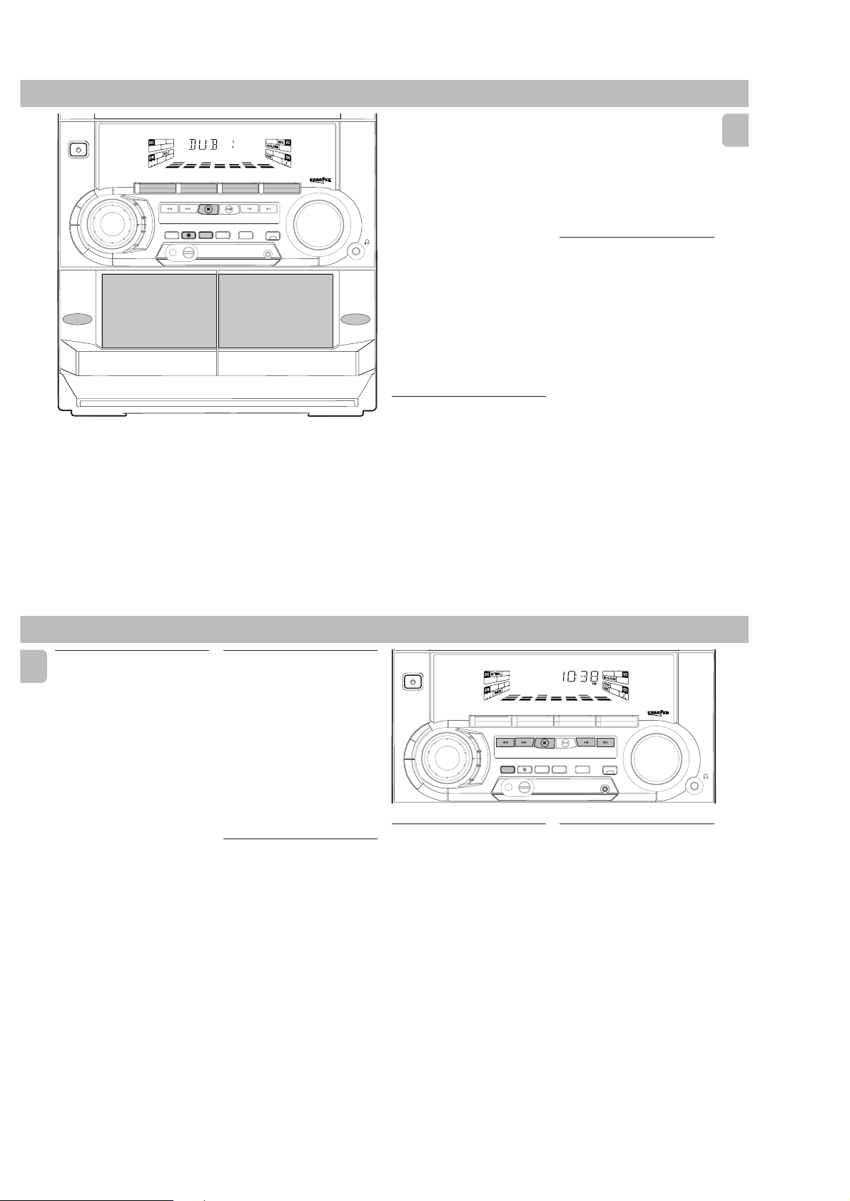
Dubbing tapes
tape deck 2)
1 Press TAPE ( TAPE 1•2 ) to select tape
deck 2.
2 Load the prerecorded tape into tape
deck 1 and a blank tape into tape deck 2
with full spool to the left.
3 Press DUBBING
™ "DUB" with "
displayed.
• Dubbing will start immediately.
™ The REC flag starts flashing.
4 Press Ç to stop dubbing.
Notes:
–At the end of side A, flip the tapes to
side B and repeat the procedure.
– Dubbing of tapes is only possible from
tape deck 1 to tape deck 2.
–To ensure good dubbing, use tapes of
the same length.
–You can listen to other source while
dubbing.
20
(from tape deck 1 to
22
2" scrolling right will be
22
Recording from other sources
(only on tape deck 2)
1 Press TAPE ( TAPE 1•2 ) to select tape
deck 2.
2 Load a blank tape into tape deck 2 with
the open side downward.
3 Press CD, TUNER or AUX.
•Start playback of the selected source.
4 Press RECORD to start recording.
™ The REC flag starts flashing.
5 Press Ç to stop recording.
Notes:
–During recording, it is not possible to
listen to another source.
Digital Recording via Digital
Out
For CD digital recording, please refer to the
Instructions Manual of the CD Recorder,
digital audio equipment, etc.
MINI HIFI SYSTEM
FW-
C10
STANDBY-ON
JOG
CD1 • 2 • 3 BAND
CONTROL
▲▲▲
B
B
D
C
E
V
C
S
D
L
A
M
I
T
P
O
N
H
C
E
T
▲
TUNING
O
Z
Z
SEARCH
A
J
K
C
O
R
STOP•CLEAR
RECORD
PROGRAM DIM
View Clock
You can view the clock (if it is set) if the
system is in Standby mode or when any
sound source is selected (CD, TUNER, etc.).
The clock will be displayed for about seven
seconds.
•Press CLOCK•TIMER briefly.
™ “10:38
™ “--:--” will be displayed if the
PM
or 22:38” (the current
time in either 12- or 24-hour mode)
will be displayed depending on
whether you have selected 12- or 24hour mode.
clock is not set.
TAPE 1 • 2
CDR/VIDEO
TAPECD TUNER
PLAY• PAUSE PREV NEXT
DUBBING A.REPLAY
SOUND NAVIGATION - JOG
▲
PRESET
INCREDIBLE
SURROUND
CLOCK•TIMER
AUX
▲
VOLUME
Clock Setting
The clock can be set in either 12- or 24hour mode, e.g. “12:00
“00:00“. Before setting the clock, you
must be in the View Clock mode.
1 Press CLOCK•TIMER to select clock
mode.
2 Press PROGRAM to select 12- and 24-
hour mode.
™ If 12-hour mode is selected,
“12:00“ starts flashing and the
lights up.
™ If 24-hour mode is selected,
“00:00” starts flashing.
3 Set the hour with à or á on the
system.
4 Set the minute with í or ë on the
system.
AM
“ or
AM
PCS 103 527

2-9
TIMER SLEEP TIMER
5 Press CLOCK•TIMER again to store the
setting.
™ The clock starts.
•To exit without storing the setting, press
Ç on the system.
Notes:
– During clock setting, if no button is
pressed within 90 seconds, the system
will exit clock setting mode
automatically.
– When a power interruption occurs, the
clock setting is erased.
Timer Setting
•The system can switch on to CD ,
TUNER or TAPE 2 mode automatically at
a preset time. It can serve as an alarm
to wake you up.
• Before setting the timer, make sure the
clock is set correctly.
•The timer will always be switched on
once it is set.
• The volume of the timer will
increase from the minimum level
until the volume level before the set
is switched to standby mode.
1 Press and hold CLOCK•TIMER for more
2 seconds
than
™ “12:00
timer setting starts flashing
depending on whether you have
selected 12- or 24-hour mode.
™ The TIMER flag starts flashing.
to select timer mode.
AM
” or “00:00" or the last
™ The selected source is lit while other
available sources are flashing.
2 Press CD, TUNER or TAPE to select the
desired source.
• Before selecting CD or TAPE, make sure
a CD or tape is loaded in the CD
carousel tray or tape deck 2
3 Press à or á on the system to set
the hour for the timer to start.
4 Press í or ë on the system to set the
minute for the timer to start.
5 Press CLOCK•TIMER to store the start
time.
™ The timer is now set.
™ The TIMER flag remains on the
display.
•At the preset time, the timer will be
activated.
™ The selected source will be played.
Notes:
–During timer setting, if no button is
pressed within 90 seconds, the system
will exit timer setting mode
automatically.
– If the source selected is TUNER, the last
tuned frequency will be switched on.
– If the source selected is CD, playback
will begin with the first track of the
selected disc or program. If the CD trays
are empty, the TUNER will be selected
instead.
–The timer will not activate if a recording
is in progress.
To s witch off the TIMER
1 Press and hold CLOCK•TIMER for more
2 seconds
than
2 Press Ç on the system to cancel the
timer.
™ The timer is now switched off.
™ The display will show "CANCEL"
and the TIMER flag disappears.
To start the TIMER again
.
(for the same
preset time and source)
1 Press and hold CLOCK•TIMER for more
2 seconds
than
2 Press CLOCK•TIMER again to store the
start time.
™ The timer is now on.
™ The TIMER flag appears on the
display.
.
Sleep Timer
This feature allows you to select a length
of time after which the system will switch
to the standby mode automatically.
1 Press SLEEP on the remote control
repeatedly to select a period of time.
™ The selections are as follows (time in
™ “SLEEP XX” or “OFF” will be
2 When you reach the desired length of
time, stop pressing the SLEEP button.
™ After this amount of time passes, the
To switch off the Sleep Timer
•Press SLEEP repeatedly until "OFF" is
displayed, or press the STANDBY ON
button.
(only on remote control)
minutes):
™™
™™
™™
60
™ 45
™ 30
™™
™™
…
displayed. "XX" is the time in
minutes.
system will switch to the standby
mode.
™ 15
™™
™™
™ OFF
™™
™™
™ 60
™™
English
21
MAINTENANCE TROUBLESHOOTING
Maintenance
Cleaning the Cabinet
•Use a soft cloth slightly moistened with
a mild detergent solution. Do not use a
solution containing alcohol, spirits,
ammonia or abrasives.
Cleaning Discs
•When a disc becomes
dirty, clean it with a
cleaning cloth. Wipe
the disc from the
center out.
• Do not use solvents
such as benzine,
thinner, commercially available cleaners,
or antistatic spray intended for analog
records.
Cleaning the CD lens
•After prolonged use, dirt or dust may
accumulate at the CD lens. To ensure
good playback quality, clean the CD lens
with Philips CD Lens Cleaner or any
commercially available cleaner. Follow
the instructions supplied with cleaner.
Cleaning the Heads and the Tape Paths
•To ensure good recording and playback
quality, clean the heads, the capstan(s),
and pressure roller(s) after every 50
hours of tape operation.
•Use a cotton swab slightly moistened
with cleaning fluid or alcohol.
•You can also clean the heads by playing
a cleaning tape once.
Demagnetizing the heads
•Use a demagnetizing tape available at
your dealer.
Warning! Under no circumstances
should you try to repair the set
yourself as this will invalidate the
guarantee. Do not open the set as
there is a risk of electric shock.
• If a fault occurs, check the points listed
below before taking the system for
repair.
• Should any problems persist after you
have made these checks, consult your
nearest dealer or service center.
CD Player Operation
“NO DISC” is displayed.
•The disc is inserted upside down.
Place CD with printed side up.
™
• Moisture condensation at the lens.
™
Wait until lens has adjusted to normal
room temperature.
•There is no disc in the CD tray.
™
Insert a CD.
•The CD is dirty, badly scratched or
warped.
Clean or replace the CD.
™
•The CD lens is dirty or dusty.
™
See section under Maintenance (page
23).
“DISC NOT FINALIZED” is
displayed.
•The CD-RW or CD-R disc is not properly
recorded for use with a standard CD
player.
Read the instruction booklet of your CD-
™
Rewritable or CD-Recorder on how to
finalize a recording.
•The CD is badly scratched or dirty.
™
Replace or clean CD.
Radio Reception
Poor radio reception.
•The signal is too weak.
Adjust the antenna.
™
™
Connect an external antenna for better
reception.
•The TV or VCR is too close to the stereo
system.
Separate the stereo system from the TV
™
or VCR.
Cannot tune to station
•Wrong tuning grid.
Switch to the correct tuning grid.
™
English
23
PCS 103 528

English
Tape Deck Operation
“RECORDING ACTIVE” is displayed.
•A recording is in progress.
Stop the recording or wait until it is
™
finished.
“TAPE DUBBING ONLY” is
displayed.
•Tape dubbing is only possible in tape
mode.
Switch source to tape mode.
™
Recording or playback cannot be
made or there is a decrease in audio
level.
•Dirty tape heads, capstans or pressure
rollers.
See section on tape deck maintenance
™
(page 23).
• Magnetic build-up in the record/
playback head.
Use demagnetizing tape.
™
Tape deck door cannot open.
• Power failure or AC power plug
disconnect from the wall outlet during
tape playback.
Reconnect the AC power plug and
™
switch on the system again.
General
System does not react when any
button is pressed.
•Electrostatic discharge.
Press STANDBY ON to switch the
™
system off. Remove the AC power plug
from the wall outlet, then reconnect the
power plug and switch on the system
again.
No or poor sound.
•Volume is not turned up.
Adjust VOLUME.
™
• The headphones are connected.
Disconnect the headphones.
™
• Speakers are not connected or are
connected wrongly.
Check that the speakers are connected
™
correctly.
™
Make sure the stripped speaker wire is
clamped.
Reversed left and right sound.
• Speakers are connected wrongly.
™
Check the speaker connections and
location.
2-10
Lack of bass sound or apparently
imprecise physical location of musical
instruments.
• Speakers are connected wrongly.
Check the speaker connection for
™
proper phasing, colored/black wires to
colored/black terminals.
Remote control has no effect on the
system.
•Wrong source is selected.
Select the source (CD, TUNER, etc.)
™
before pressing the function button,
É,í,ë
(
• The distance to the system is too large.
Reduce the distance.
™
• Batteries are inserted incorrectly.
™
Insert the batteries with their polarities
(+/– signs) as indicated.
• Batteries are exhausted.
Replace the batteries.
™
, etc.).
TROUBLESHOOTING
Timer is not working.
•Clock is not set.
Set the clock.
™
•Timer is not switched on.
Press CLOCK•TIMER to switch on the
™
timer.
•Recording is in progress.
Stop recording.
™
Clock setting is erased.
•There was a power failure.
Reset the clock.
™
System displays features
automatically; buttons flash
continuously.
• Demonstration mode is switched on.
Press and hold Ç (on the system) for 5
™
seconds to switch off the
demonstration.
All lighted buttons are not lit.
•Display is switch on in DIM 3 mode.
Press DIM until DIM OFF display mode
™
is shown.
24
ADDITIONAL FEATURES FOR /22/34
Receiving RDS Radio Station
Ç
RDS (Radio Data System) is a broadcasting
service that allows FM stations to send
additional information along with the
regular FM radio signal. This additional
information can contain:
• STATION NAME: The radio station
name is displayed.
• PROGRAM TYPE: The following
program types exist and can be received
by your tuner: News, Affairs, Info, Sport,
Educate, Drama, Culture, Science,
Varied, Pop M, Rock M, M.O.R. (middle
of the road music), Light M, Classics,
Other M, No type.
• RADIO TEXT (RT): text messages
appear in the display.
When you have tuned to a RDS station, the
RDS logo (Ç ) and the radio station name
will appear on the display:
• The display normally shows the radio
station name if available.
By repeatedly pressing RDS button you
can change the type of display
information:
™ The display shows in turn:
STATION NAME ™ PROGRAM
TYPE ™ RADIO TEXT ™
TUNED FREQUENCY ™
STATION NAME ...
Note:
–When you press the RDS button and the
NO RDS
display shows "
", it indicates
that either the tuned station is not
transmitting RDS signal or it is a non
RDS station.
RDS Clock
Some RDS station may be transmitting a
real clock time at an interval of every
minute.
Setting the time with RDS clock
1 Press CLOCK•TIMER.
::
™ "--
:--" or current time appears on
::
the display.
2 Press CLOCK•TIMER once more to
enter clock setting mode.
::
™ "00
:00" or current time starts
::
flashing.
3 Press RDS.
™ The message "SEARCH RDS
TIME" will be displayed.
™ If the current station is not receiving
any RDS information, "NO RDS
TIME" will be displayed.
™ When the RDS clock is read, "RDS
TIME" will be displayed. The
current clock time is displayed for 2
seconds and will be stored
automatically.
™ If within 90 seconds, the RDS time is
not detected, "NO RDS TIME" will
be displayed.
Note:
– Some RDS station may be transmitting a
real time clock at a minute interval. The
accuracy of the transmitted time
depends on the transmitting RDS
station.
News
(only available in Radio Station
with RDS)
You can activate NEWS function in Standby
or any source mode except Tuner mode.
Once the News PTY (program type) is
detected in a RDS station, it will switch to
TUNER mode automatically.
To start NEWS function
1 Press NEWS.
NEWS
•The
• It will scan stations stored in the first 5
and "NEWS" will be displayed.
preset and wait for the News Program
Type data to be available in any of these
RDS stations. During the search :
™ The current source activity will
remain uninterrupted.
™ If no RDS station is found in the first
5 presets, the NEWS function will be
switched off. The display will show
"NO RDS NEWS" and
disappear from the display.
•When NEWS transmission is detected,
the system will switch to Tuner mode.
NEWS
™ The
To cancel NEWS function
•Press NEWS again.
™ The
starts flashing.
NEWS
disappears and "NEWS
OFF" will be displayed.
NEWS
will
Notes:
– If you are listening to a non RDS TUNER
radio station and should you decide to
hear NEWS, first select other source
(e.g. CD, TAPE or AUX), then press
NEWS.
–Before using the NEWS feature, ensure
that the first 5 presets are RDS stations.
– The NEWS works only once for each
activation.
–During News bulletin, you can press any
available source or Tuner function keys
to cancel NEWS function and execute
the relevant source mode.
– If set is switched to Tuner source, the
NEWS function will be cancelled,
NEWS OFF
"
immediately after the "
" will be displayed
TUNER
"
message.
English
PCS 103 529
1
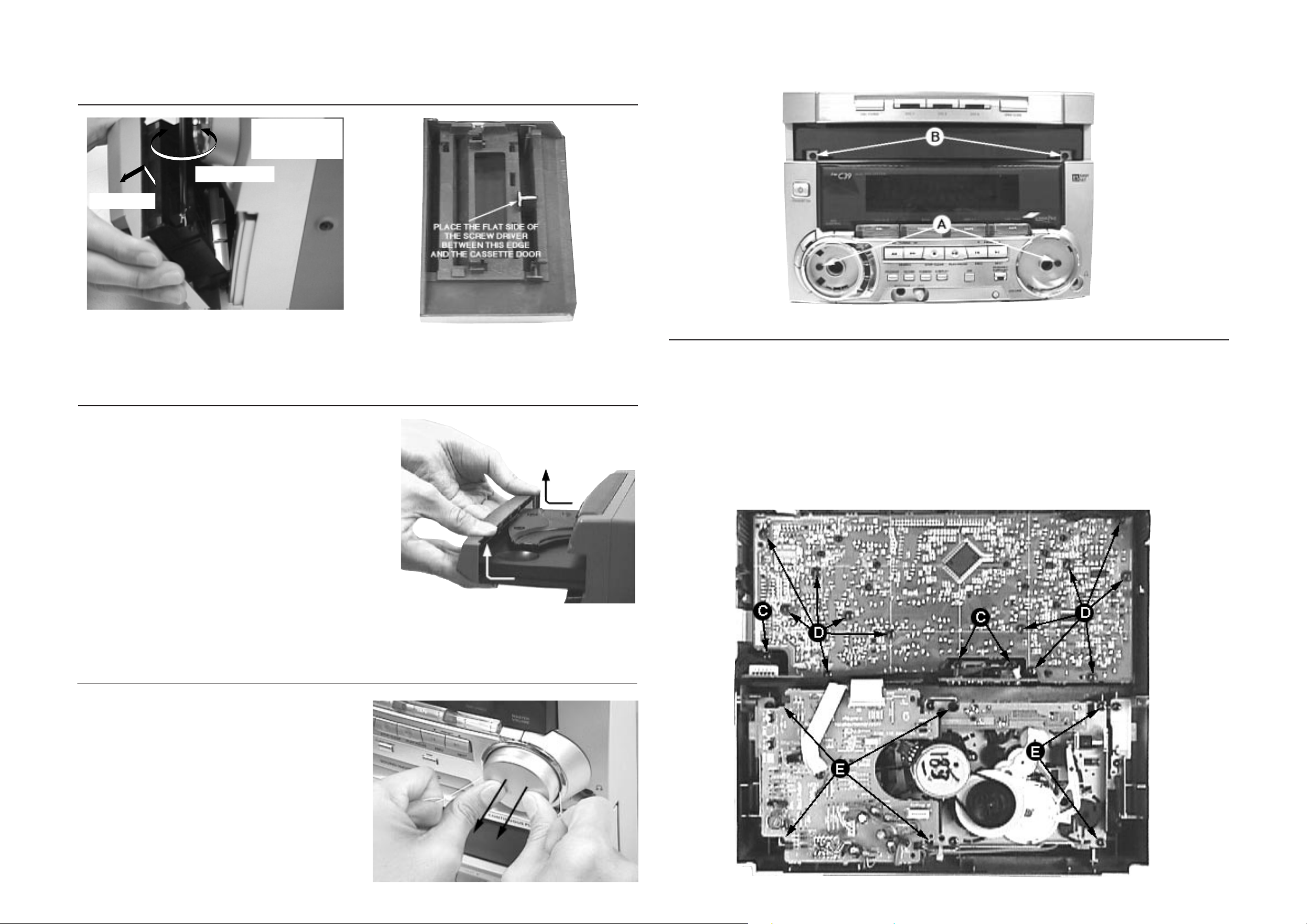
DISMANTLING INSTRUCTIONS
Dismantling of the Cassette Cover
1. Place screw driver
(flat side) between
the cover & cassette
door
2. Twist screw driver
3. Lift up and out
3-1 3-1
Dismantling of the Front Panel
1) Slide out the tray an remove the Cover Tray CDC (pos 107)
as indicated.
2) Loosen the 8 screws to separate the Front Panel from the
rear portion.
-2 screws B on the front
-2 screws each on the left & right side
-2 screws at the bottom
Cassette Cover
Dismantling of Assemblies on the Front Panel
1) Remove the Volume and Jog Rotary knobs (pos 145 &
146) as per step 1 and 2 of
Dismantling the Cover
Control on the Front.
2) Remove 3 screws C to loosen the Headphone board (1x)
and the Karaoke board (2x).
Note: Karaoke board is for some versions only.
3) Remove 12 screws D as indicated to loosen the Front
board.
4) Remove 6 screws E to loosen the ETF7 Module
Dismantling of the Cover Control on the Front (see Notes)
1) Insert a strong string into the slot between the Volume
knob (pos 146) and Cover Ring Volume (pos 144, looped
it 1,5 turns securely around the Volume knob and pulled it
out as shown.
2) Do likewise for the Jog Rotary knob (pos 145).
3) Remove the 2 hidden screws A to take out the Cover
Control Assembly (pos 153 + 143 + 144).
Note: Only the Lightguide DSC (pos 127) is sandwiched
between the Front Cabinet (pos 101) & Cover Control
(pos 153).
PCS 103 530
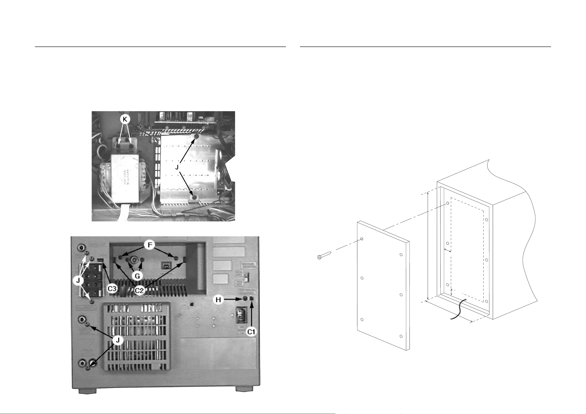
3-2
W
H
2cm
2cm
Chip Board size: H x W
Thickness: 5 - 8mm
Rear View of Loudspeaker Box
Speaker wire
3-2
Dismantling of Rear Portion
1) Remove 1 screw H & uncatch C1 to loosen the Mains
socket board.
2) Remove 2 screws F, 2 screws G and uncatch C2 to
loosen the Tuner board assembly.
3) Remove 7 screws J (5x on the rear and 2x on the
heatsink) and uncatch C3 to loosen the Combi board
(Main part).
4) Remove 2 screws K to loosen the Mains Transformer.
Dismantling of Left/Right Loudspeaker Box (not recommended because of high risk of damage)
This Loudspeaker Box is not designed to be repaired!
The steps below makes it possible to replace defective
parts but the service repairman must exercise extreme
care not to damage the Louspeaker box.
1) Marked out a rectangular area on the Rear of the
Loudspeaker box giving it a 2cm skirting all round (see
picture).
2) Use a zigsaw (or open-end hand-held saw) cut along the
earlier marked out line.
Caution: Be extra careful not to cut the Loudspeaker
Wires near the bottom of the LS box.
3) Prepare a Chipboard (thickness 5 - 8 mm) of size L x W
to cover back the cut-out after replacement of defective
parts.
4) Use any self-tapping wood screw to tighten the new
Chipboard onto the 2cm width skirting.
PCS 103 531
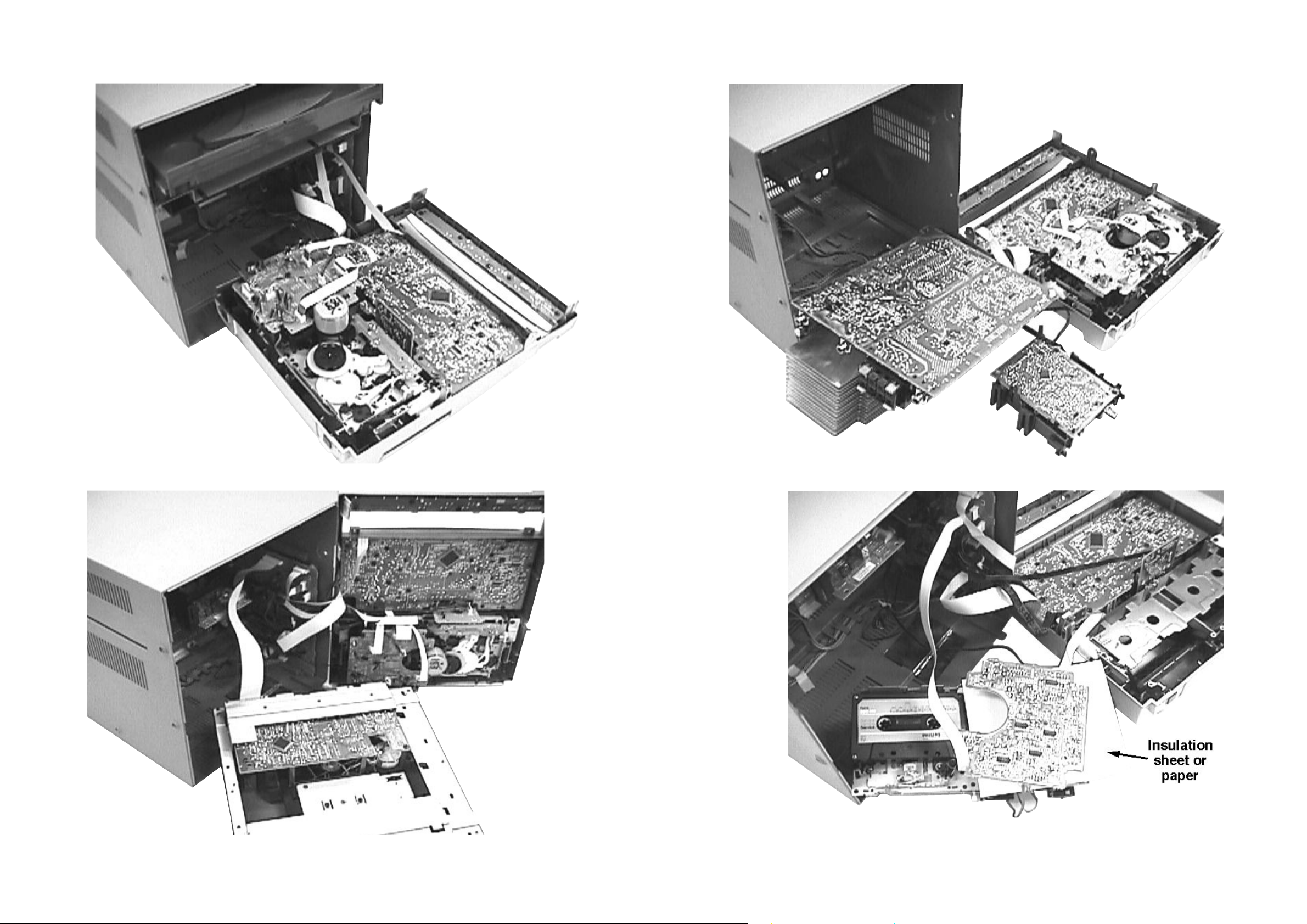
3-3
3-3
Service pos A
Service pos C
Service pos B
Service pos D
Notes:
1. During repair it is possible to disconnect the following
assemblies or modules while repairing other areas:
-Tuner Board
- CDC Module
2. The flex cables are very fragile, care should be taken not
to damage them during repair. After repair, be very sure
that the flex cables are inserted properly into the flex
sockets before encasing, otherwise faults may occurs.
PCS 103 532
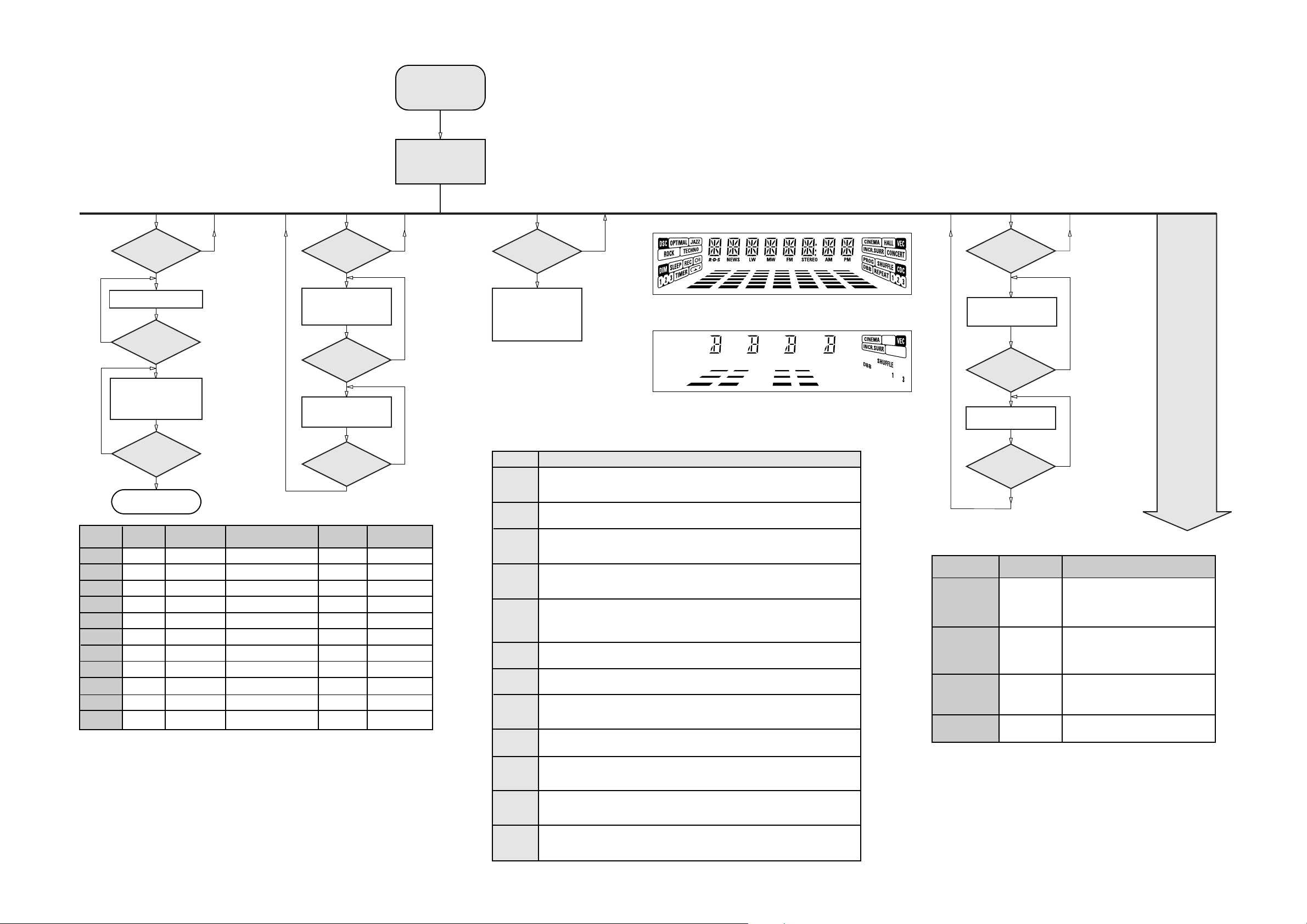
3-4
3-4
SERVICE TEST PROGRAM
TUNER
TEST
TUNER
Button pressed?
Y
Display Tuner Version
"ccc"
N
TUNER
Button pressed?
Y
Service frequencies are
copied to the RAM (see Table1)
Tuner works normally
except:
PROGRAM button
N
QUARTZ
TEST
O
Button pressed?
Y
Display shows
32K
Output at (Front Board)
pin 80 of uP = 2048Hz
O
Button pressed?
Y
Display shows
8M
Output at (Front Board)
pin 80 of uP = 1,953.125Hz
To start service test program
hold P & AUX
depressed while
plugging in the mains cord
Display shows the
ROM version *
"S-Vyy"
(Main menu)
N
N
S refers to Service Mode.
V refers to Version.
yy refers to Software version number of Processor.
(Counting up from 01 to 99)
SERVICE
PLAY MODE
POWER
Button pressed?
Y
Set is in Service PLAY Mode.
In case of failures, error
codes according to table 2
will be displayed.
The Service Play Mode is intended to
detect and identify the failures in the CD Mode.
In this mode the electronics will still function
even when an error is detected so that
repair activities can be carried out.
N
Figure 1
note 1 : DISC1, DISC3, TUNER, JAZZ and TECHNO
Figure 2
DISPLAY
TEST
2
Button pressed?
Y
Display shows Fig. 1
and switch all LEDs on
2
Button pressed?
Y
Display shows Fig. 2
and selected LEDs on
(see note 1)
N
N
N
Disconnect
PRESET
1
2
3
4
5
6
7
8
9
10
11
Mains cord ?
Y
Service Mode left
Europe
"EUR"
87.5MHz
108MHz
531kHz
1602kHz
558kHz
1494kHz
153kHz
279kHz
198kHz
98MHz
87.5MHz
East Eur.
"EAS"
87.5MHz
108MHz
531kHz
1602kHz
558kHz
1494kHz
87.5MHz
87.5MHz
87.5MHz
87.5MHz
98MHz
East Eur. Extended-band
"EAS"
65.81MHz
108MHz
74MHz
87.5MHz
531kHz
1602kHz
558kHz
1494kHz
98MHz
70.01MHz
65.81MHz
Table 1
9
Button pressed?
Y
USA
"USA"
87.5MHz
108MHz
530kHz
1700kHz
560kHz
1500kHz
98MHz
87.5MHz
87.5MHz
87.5MHz
87.5MHz
Note: * Depending on the selected grid frequency (9 or 10kHz)
By holding the TUNER and R buttons depressed while switching on the Mains supply, one
of the undermentioned features will be activated:
- the tuning grid frequency is toggled between 9kHz and 10kHz for the Oversea (/21) version.
- the extended FM1 (65.81MHz - 74MHz) is toggled on and off for East Eur. (/34) version.
N
Oversea
"OSE"
87.5MHz
108MHz
531/530kHz*
1602/1700kHz*
558/560kHz*
1494/1500kHz*
87.5/98MHz*
87.5MHz
87.5MHz
87.5MHz
98/87.5MHz*
Error code
E1000
E1001
E1002
E1003
E1005
E1006
E1007
E1008
E1020
E1070
E1071
E1079
Error Description
Focus Error
Triggered when the focus could not be found within a certain time when starting up the CD
or when the focus is lost for a certain time during play.
Radial Error
Triggered when the radial servo is off-track for a certain time during play.
Sledge In Error
The sledge did not reach its inner position (inner-switch is still close) before approximately
6 Sec. have passed by. Inner-switch or sledge motor problem.
Sledge Out Error
The sledge did not come out of its inner position (inner-switch is still open) before approximately
250 mSec. have passed by. Inner-switch or sledge motor problem.
Jump-offtrack error
Triggered in normal play when the jump destination could not be found within a certain time.
When this error occurred, software will try to recover by initiating the jump command again.
If it is recoverable, the disc will continue to play.
Subcode Error
Triggered when a new subcode was missing for a certain time during play.
PLL Error
The Phase Lock Loop could not lock within a certain time.
Turntable Motor Error
Generated when the CD could not reached 75% of speed during startup within a certain time.
Discmotor problem.
Focus Search Error
The focus point has not been found within a certain time.
The carousel switch is not open within certain time. This can happen when either the switch is
defective and closed all the time, or when the carousel is blocked when located exactly at a
disc position.
The carousel position switch did not close within a certain time. This can happen when the
switch is defective and never closes electrically, or when the carousel is blocked in between
two disc positions. The time-out is approximately 5 Sec.
The drawer could not enter the inside position is opening again. This can be caused because
the drawer is blocked by something and cannot go fully inside, or the drawer switch is defective
and does not close.
9
Button pressed?
Y
TEST
Activated with
EEPROM TEST A test pattern will be sent to the EEPROM.
9 to Exit
ENCODER TEST Display shows value for 2 seconds.
Volume Knob
Jog Shuttle knob
LEAVE SERVICE
TESTPROGRAM
Disconnect
mains cord
N
Various
other Tests
ACTION
R
QEEPROM FORMAT Load default data. Display shows "NEW"
or
"PASS" is displayed if the uProcessor read
back the test pattern correctly, otherwise
"ERROR" will be displayed.
for 1 second.
Caution!
All presets from the customer will be lost!!
Values increases or decreases in steps of 1
until 0 (Min.) or 40 (Max.) is reached.
PCS 103 533
Table 2
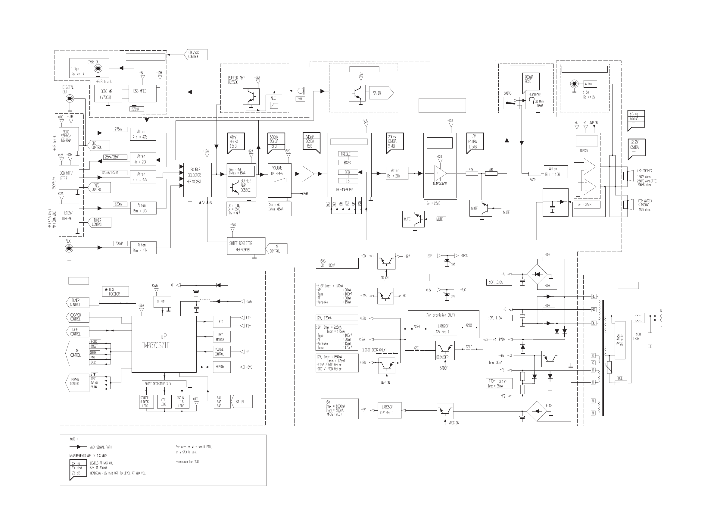
SET BLOCK DIAGRAM
VCD MODULE
4-1
4-1
SIMPLE KARAOKE
SA BUFFER
#
SOUND PROCESSING
COMBI
HEADPH0NE
AMPLIFIER
HEADPHONE
SUBWOOFER OUT
BASS ALC
POWER
AMPLIFIER
For 12W set
Only
For 25W set
Only
FRONT
FRONT
**
**
POWER SUPPLY
TRAFO
VCD
#
VCD
#
VCD
VCD
#
#
Updated on 10-06-99
PCS 103 345
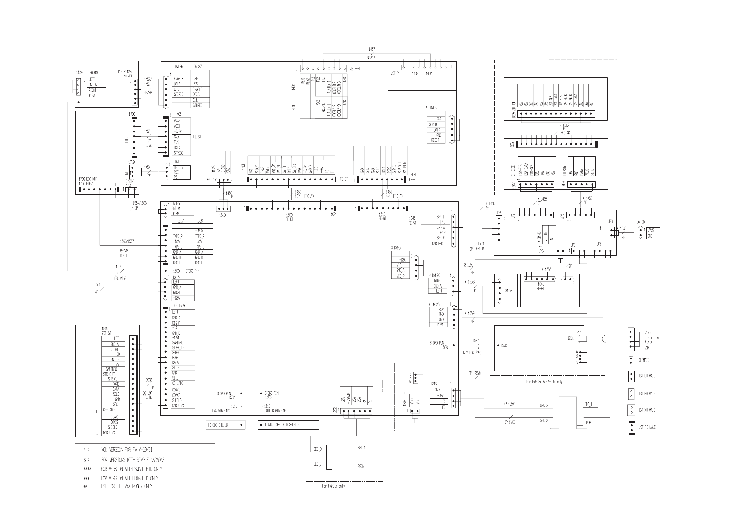
SET WIRING DIAGRAM
5-1
5-1
ECO5 / TUNER95
ECO-MTF/
ETF7
ECO5
ECO-MTF
TU95
ETF7
***
****
FRONT
3CDC-99
/
CDC KEY
HEADPHONE
# 3CDC SERVO FOR VCD
VCD
3CDC 99
COMBI
KARA
# MPEG-ESS
# CVBS OUT
HEADPHONE
MIC
MAINS
M/TOP B3P-VH
TRAFO
PCS 103 244
TRAFO
4W
FW-C10/37 3139 119 32240 dd wk939

6-1
FRONT BOARD
TABLE OF CONTENTS
FTD Display pin connection ............................................ 6-2
Variation table .................................................................. 6-3
Circuit diagram.................................................................6-4
Component & Chip layout ...............................................6-5
Electrical parts list............................................................ 6-6
PCS 103 245
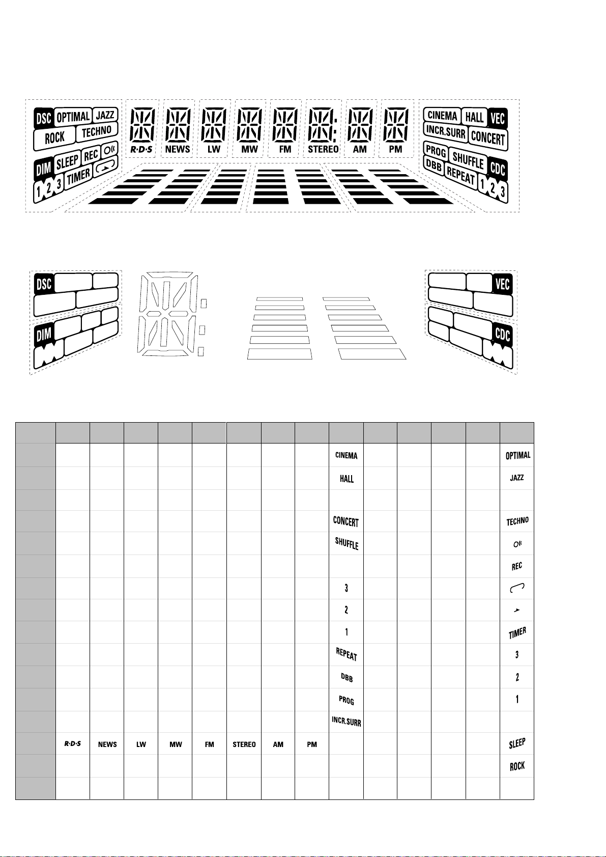
FTD DISPLAY PIN CONNECTIONS
6-2
S3
S4
14G
f
e
2G1G 4G3G 9G8G7G6G5G
12G 11G 10G13G
a
h
j
k
b
g
m
Col
r
j
d
1G - 8G
n
c
Dp
A3
A2
A1
A4
A5
A6
10G - 13G
B6
B5
B4
B3
B2
B1
S1
S2
P1
P2
P3
P4
P5
P6
P7
P8
P9
P10
P11
P12
P13
1G
m
2G
a
h
a
h
j
k
b
k
b
f
m
g
c
e
g
c
e
r
n
d
n
d
3G
j
f
m
r
4G
a
h
a
h
j
k
b
k
b
f
m
g
c
e
g
c
e
r
n
d
n
d
5G
a
h
j
k
b
f
m
g
c
e
r
n
d
6G
7G
a
h
j
j
k
b
f
f
m
m
g
c
e
r
r
n
d
8G
a
h
j
k
b
f
a
h
j
k
b
f
m
g
c
e
r
n
d
g
c
e
r
n
d
9G
S1
S2
10G
A1
A2
A3
A4
A5
A6
-
-
B1
B2
B3
B4
B5
11G
A1
A2
A3
A4
A5
A6
B1
B2
B3
B4
B5
12G
A1
A2
A3
A4
A5
A6
-
-
13G
A1
A2
A3
A4
A5
A6
-
-
-
-
-
-
-
B1
B2
B3
B4
B5
14G
S3
-
-
S4
P14
P15
P16
PCS 103 534
B6
-
-
-
-
-
-
-
-
-
-
Dp
-
Col
-
-
-
-
-
-
-
-
B6
-
-
-
-
-
B6
-
-
-

6-3
6-3
Front Board application
A5272 FW-C1/37, FW-C10/22/34/37
A5273 FW-C3/37, FW-C30/30/37, FW-C35/37
A5274 FW-C38/21/21M, FW-C39/21/21M/33
A5275 FW-C28/33
A5276 FW-C38/22/34
A5277 FW-C28/22/34
A5307 FW-C30/21/21M
A5308 FW-C38/37, FW-C39/30
A5344 FW-V39/21M/21K
A5348 FW-C10/21
A5350 FW-V28/21M
A5365 FW-C28/21M
FEATURES: A5272 A5273 A5274 A5275 A5276 A5277 A5307 A5308 A5344 A5348 A5350 A5365
RDS - - --xx-----Rotary Volume - x x x x xxxx-xx
Jog Control - x x - x - x x x - - Spectrum Analyzer - - x - x - - x x - - Biplaner LED - x x x x xxxx -xx
Small FTD x x - x - x x - - x x x
Large FTD - - x - x - - x x - - -
Variations table for Front Board
ITEM NO. A5272 A5273 A5274 A5275 A5276 A5277 A5307 A5308 A5344 A5348 A5350 A5365
DM21 x x - - - - x - - x - DM23 - - - - - - - - x - x DM26 x x x x - - x x x x x x
DM27 - - - - x x - - - - - 1402 - - x - x - - x x - - 1403 x x - x - x x - - x x x
1404 x x x x x x x x - x - x
1405 - - x x x x - x x - x x
1418 - - x - x - - x x - - 1419 - - x - x - - x x - - 1420 - - x - x - - x x - - 1421 - - x x x x - x x - x x
1423 - - x x x x - x x - x x
1425 - - - x x x - - x - x 1426 - - x x x x - x x - x x
1427 - - - - x x - - x - x 1428 x - - - - - - - - x - 1429 x - - - - - - - - x - 1430 x - - x - x - - - x x x
2417 - 220µF 220µF 220µF 220µF 220µF 220µF 220µF 220µF-220µF 220µF
2421 2,2µF22µF22µF22µF22µF22µF22µF22µF22µF 2,2µF22µF22µF
2432 - - - - 100pF 100pF - - - - - 2433 - - - - 47pF 47pF - - - - - 2462 - 220nF 220nF 220nF 220nF 220nF 220nF 220nF 220nF - 220nF 220nF
ITEM NO. A5272 A5273 A5274 A5275 A5276 A5277 A5307 A5308 A5344 A5348 A5350 A5365
3407 - - 1k - 1k - - 1k 1k - - 3458 - - 1k - 1k - - 1k 1k - - 3460 - - 1k - 1k - - 1k 1k - - 3465 - 1k 1k 1k 1k 1k 1k 1k 1k - 1k 1k
3471 4R7 4R7 1R 4R7 1R 4R7 4R7 1R 1R 4R7 4R7 4R7
3479 - 1k 1k 1k 1k 1k 1k 1k 1k - 1k 1k
3483 4R7 4R7 1R 4R7 1R 4R7 4R7 1R 1R 4R7 4R7 4R7
3516 330R - - - - - - - - 330R - 3518 - - 330R - 330R - - 330R 330R - - 3524 - - 1k 1k 1k 1k - 1k 1k - 1k 1k
3539 10k 10k 10k 10k - - 10k 10k 10k 10k 10k 10k
3541 - - - - 1k 1k - - - - - 3546 10k 10k 10k 10k - - 10k 10k 10k 10k 10k 10k
3555 10k 10k - 10k - 10k 10k - - 10k 10k 10k
3575 10k 10k - 10k - 10k 10k - - 10k 10k 10k
3576 10k 10k - 10k - 10k 10k - - 10k 10k 10k
3577 - - 12k - 12k - - 12k 12k - - 3578 - - 5k6 - 5k6 - - 5k6 5k6 - - 3586 - - 1k - 1k - - 1k 1k - - 3588 10k - - - - - - - - 10k - 3600 5k6 5k6 - 5k6 - 5k6 5k6 - - 5k6 5k6 5k6
3602 10k 10k - - - - 10k - - 10k - 3603 6k8 10k 10k 10k 10k 10k 10k 10k 10k 6k8 10k 10k
3613 47k 12k 12k 12k 12k 12k 12k 12k 12k 47k 12k 12k
4400 x - - x - x - - - x x x
4407 x x - x - x x - - x x x
4412 - - x - x - - x x - - 4413 x - - - - - - - - x - 4417 x - - x - x - - - x x x
4436 x - - x - x - - - x x x
6401 - x x - x - x x x - - 6402 - - x - x - - x x - - 6404 - x x - x - x x x - - 6405 - - x - x - - x x - - 6420 - - x - x - - x x 6422 x - - - - - - - - x - 6423 - - x x - - x - x x - 6424 - x - - - - x - - - - 6428 - x x x x x x x x - x x
6433 - x - - - - x - - - - 6445 x - - x - x - - - x x x
6446 x - - x - x - - - x x x
6447 x x - x - x x - - x x x
9475 x x - x - x x - - x x x
9488 - x x - x - x x x - - 9520 - x x - x - x x x - - 9523 x x - x - x x - - x x x
x = Item in use.
PCS 103 462
 Loading...