

Page 1
FIELD
SERVICE
BULLETIN
Date:
File
Group:
ATTENTION:
Setting/Adiusting
This
bulletin is
exceot FLEX AirrM
Trac
suspensions. lt
on those vehicles.
.
This
bulletin
Spring Height
nance manual
updated in
The
ride height
used
are designed to
teristics.
There
been
are occasions when
put
in
service. Peterbilt recommends
'
Changing the ride height results
tion can lead
'
Changing
result in
April7,2004
03 Section:
ServiceManager
RearAxle Angles:
applicable to vehicles
suspensions;
provides a procedure
supersedes the information
(Ride
the near future
proprietary
of
to driveline vibration.
ride
the
complaints
Height)" in
for vehicles
to reflect the
rear
provide
height may
the vehicle
a customer will
rough
of
Rear
Suspension
Proprietary
equipped with
i.e., Air Leaf,
to set ride height
"Measuring
on
Section 6,
equipped
air suspensions
with the best
in
a change in rear
have
a detrimental effect
ride.
"Rear
as described
changes made
reset or
against this for
A DIVISION OF
Distribution
/Dealer Principal
lWarranly Manager
/Parls Manager
/Sales Manager
RearAir
Low Air Leaf, Low
adjust the ride height
Susoensions Except FLEXA|TTM
proprietary
and adjust rear
Pinion Angle"
Suspension" of the master mainte-
above. The manual will
by this bulletin.
is set
at the
possible
following
the
axle driveline
on axle travel, and may
rear
air suspensions
Low Air Leaf, and Air
and
factory.
axle travel
The specifications
and
after a
reasons:
angles.
ilqN
Copy:
axle angles
"Setting
ride
vehicle has
This
Air
be
charac-
situa-
also
Peterbilt
by maintaining
angle(s)
cedure that removes
on 6/26199
and interaxle
cellation as well
supporting information
for
this
Parts
The
using normal
recommends
the ride height
should be returned
(Denton)
driveshaft angles
as keep torsional
procedure
Notes
parts
referred
is available from
to in
ordering
that
the
and 814199
is
procedure.
Part Number
+z-uuz]v-uu1
-002,
J3-U6 /6U-0U1
Pro
3600 Anglemaster
PS803035
,
-003, -004
customers be
at the factory
to the original factory
effect of
contained in
this bulletin are listed
frame
(Madison).
provide
to
acceleration
PACCAR Parts
Kroe
Axle
Inclinometer (available
http://www.
encouraged
rake variation
Using this method
the best
this bulletin. The
nergnr roor (gauge)
(for
shim
penntoolco.
F.S.B.
# 3-00R
to avoid these
setting.
within
below
When necessary
specification. A new
pinion
on
permits
possible
specifications. The
(see
and available from PACCAR
axle travel
special ride height
Parts
Notes below).
Description
Low Air
Leaf
suspensions on/after 415104)
at
com/cataloq/products/697.
potential problems
rear
the
adjustment
angles was implemented
setting
and U-joint can-
rear
procedure
tool required
Page
axle
pro-
driver
and
Parts
cfm)
1 of 42
Page 2
Setting and Adjusting Ride
Height and Rear Axle Angles
WARNING!
This
mission in neutral
parked
on both
on a completely
sides.
Failure
vehicle rolling into
ble serious
personal
NOTE: Suitable wheel
Follow
1.
Ensure that
.
Ride height tool
.
Pro-3600
.
Adapter for Anglemaster
2.
Drive the vehicle
cle and slowly
procedure
this
or
to set ride height
following
the
(gauge)
Pro-360 Anglemaster
onto a
drive back onto the flaUlevel
transmission in neutral
3. Chock the front wheels
4. Release
Ensure
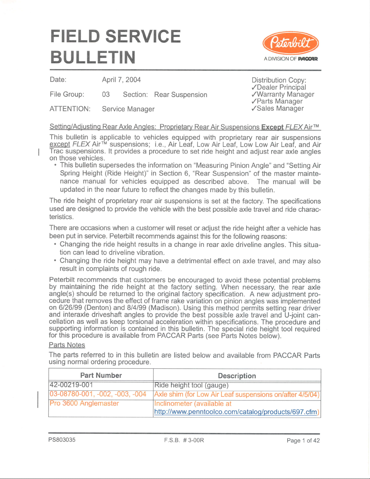
5.
the vehicle
parking
the
brakes.
that the ride height
"NOTES"
(see
procedure
and the
requires
parking
flaUlevel
to adequately
someone/something,
injury
and/or equipment
chocks are at a minimum
and adjust
tools are available:
(inclinometer)
flaUlevel
and set the
surface. Back
parking
on both sides.
gauge
in Figure
has
the correct slide installed for
1).
seruicing
brakes
released. The vehicle must
surface with
chock the
vehicle with
the
front wheels
both
wheels may lead
causing an accident and
damage.
18-inch
an
rear
axle angles
straight out for the
(46
(pinion
length
surface. Gently roll to a stop.
brakes.
the suspension
the trans-
chocked
to the
possi-
long 4x4
cm)
angles).
of the
Place
be
vehi-
the
on
LOW AIR LEAF
axle conirgurations burll
on & atter 4/904) and
LOWLOWAIR
Lol^/ AIR LEAF
(includes
conliguralons built
belore 4/5/04)
Figure
(Srngle
Srngle
U\
1 lllustration
-3t MOVE GAGE UNDER RAIL BETWEEN TANDEMS
ANO
RAISE SLIDE TO CONTACT BOTTOi' FI-ANGE
,/
SOUEEZ E TABS TO
SLIDE POINTER
TIGHTEN WING NUT
TO HOLD POINTER
POSITION
l
DOES PROPER INDICATOR
APPEAR IN TOLEMNCE AOX?
YES.
G@D
NO - ADJUST BIDE HEIGHT
LooK HERE TO
INDICATOR GROOVE PER SI.JSPENSION
o
1) PLACE BASE ON LEVEL GROUNO
NEAR REAR REAR AXLE
Ride Height
of
GROOVE
APPLY PN, REV LEVEL
AND
SUPPLIER CODE
DETERMINE PROPER
1 ,42d218-001.
2 42{n'217
3
142{0216{01,
n
lseecen
"tr-t@
BASE
-0o1,SLIDE
(ALTERMTE
POINTER
.zso' ALuMTNUM TUBTNG, 4-1l,16'
lwr
Gauge
----->
2) AL|GN POTNTER W|TH AXLE HUB HOLE
NOTES:
1) WITH
AIR LEAF, AIR TRAC, LOW AIR LEAF
AND LOW LOW AIR LEAF USE STANDARD
42-0021
sLIDE
2) WITH
-USE
ALTERNATE SLIDE 42.OO22O.OO1
wrTH
3) SPACER
OUTER TUBE OF ITEM 1
4) DASH VARIATION
MATERIAL LIST
SLTDE 42-00220-001, SEE NOTES 1 AND 2)
7-001
REYCO 1O2AR AND NEWAY AIR SUSPENSIONS
ASSEMBLY
42-00219-001
(ITEM
4)
LOOSE IN
SITS
INDICATES TOOL NUMBER
LoNG)
)
BOTTOM OF
(NOT
INCLUDED
Page2
of
42
F.S.B. # 3-00R PS803035
Page 3

6.7.Place
ground
Align the
ride height
the
(see
Figure
pointer
gauge
1 and Figure 2
of the
gauge
near
rearmost
the
axle such that
).
with the axle hub hole
(see
the base
Figure 2).
is
on
level
a. Squeeze the tabs to slide
b. Tighten the wing nut
ALIGN POINTER WITH AXLE HUB HOLE
to
hold
the
the
,-
pointer
pointer
-->
proper position.
into
in that
position.
Figure
PS803035
2 lllustration
Aligning The
of
Pointer of a Ride Height
F.S.B.
# 3-00R Page
Gauge
3 of
42
Page 4
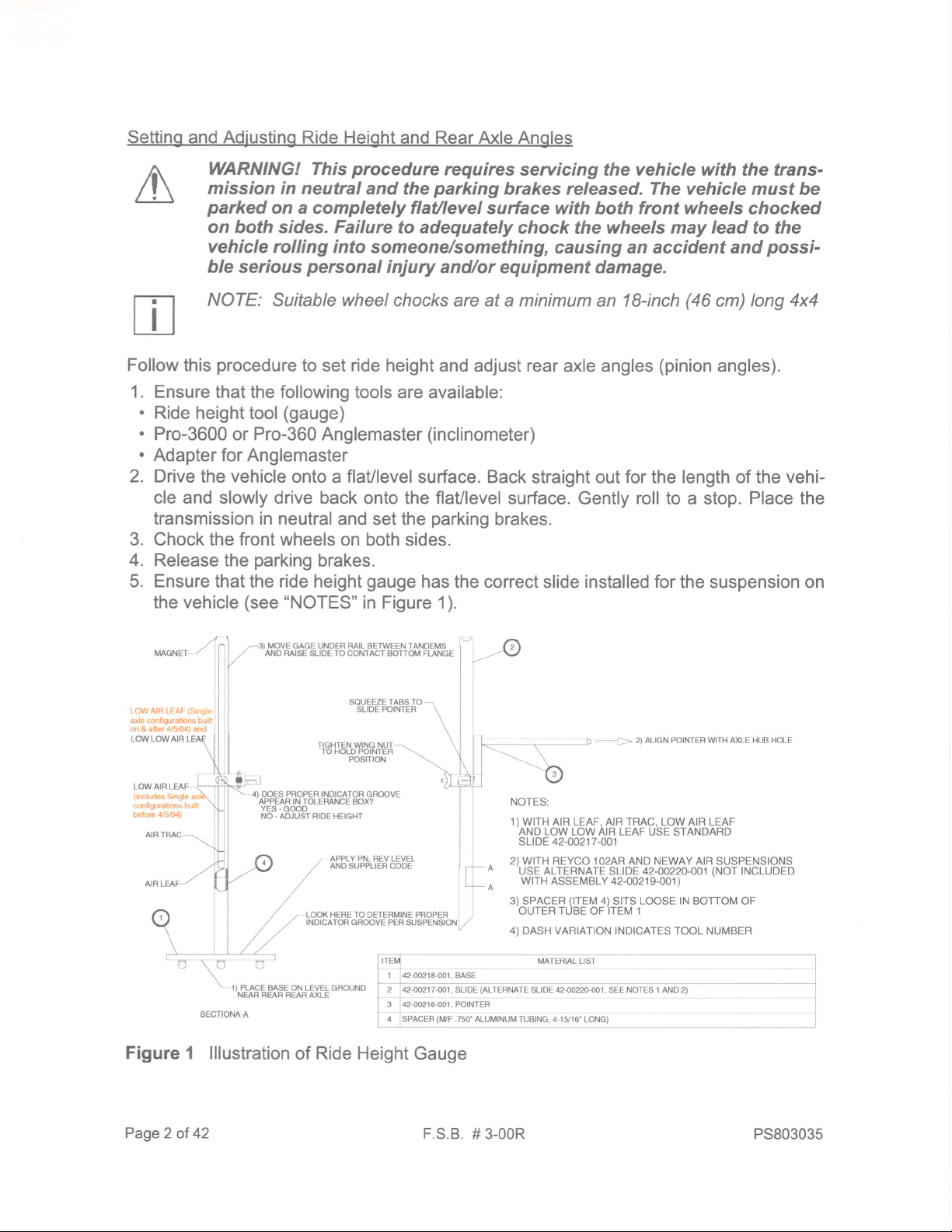
8. Move the ride height
not forward
of the suspension
gauge
under the frame rail,
bracket) or between
either
forward
tandem axles
of a single axle
(see
Figure 3).
(but
Figure 3 lllustration
9. Raise the slide
of Measuring The
to bring the magnet
frame rail.
Page
4 ot 42
Ride Height
its
at
F.S.B.
into
tip
# 3-00R
Tandem
on a
contact with
Suspension
the bottom
flange
PS803035
of the
Page 5
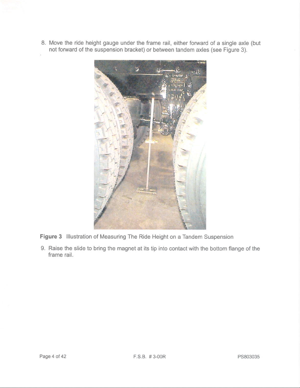
10. Look in
.
.
lf
lf
the
the
MAGNET
proper
proper
the tolerance box
,\
,/
groove
groove
.)
/
,/
appears, skip to
doesn't appear,
MOVEGAGEUNDERRAILBETWEENTANDEMS
AND RAISE SLIDE TO
note
and
what indicator
Step
perform
COMTACT BOTTOM FLANGE
groove
16
in this
procedure.
all remaining
appears
(see
steps in this
Figure 4).
procedure.
LOW AIF
axle conliguraions buill
on & after 4/5/G) and
LOWLOWAIR
(Srngle
LEAF
LOW AIR LEAF
(nrcludes
Single a)
configuralons burll
belore 4/Y04)
";1\
DOES PROPER INOICATOR
APPEAR IN TOLEMNCE BOX?
YES.
NO.
ADJUST RIDE HEIGHT
.|
f
G@D
orr/il
Figure 4 lllustration
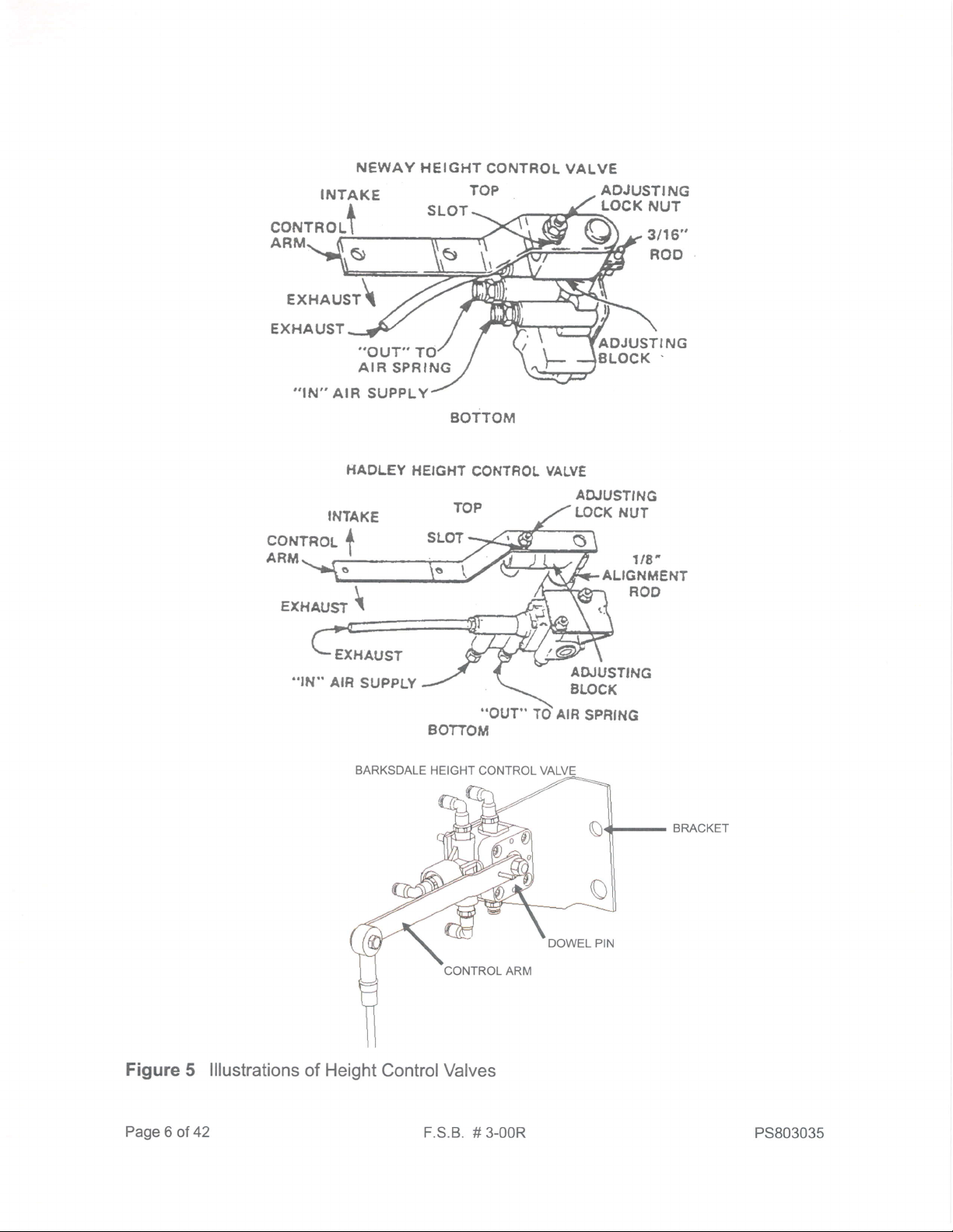
11.Loosen
for
the fasteners
illustrations
NOTE:
At least
be slotted
of
permit
to
of
height
GROOVE
LOOK HERE TO OETERMINE PROPER
INOICATOR
GROOVE PER SUSPENSIoi']
Checking Ride Height lndicator
mounting
the height control valve
control valves.
one of the mounting holes
rotating
the valve.
in the height
to its bracket.
control
valve
Figure5
See
bracket will
12.Rotate
height
13.When
the valve
as measured
at the
the neutral
dowel.
14.Torque
the mounting
15. Remove
PS803035
either clockwise
with the ride height
appropriate ride height,
position,
then install either
fasteners to
the alignment
pin
or dowel.
or counterclockwise
gauge.
ensure that
the built-in
55 - 75 Lb. in.
F.S.B.
# 3-00R
the height control valve lever is in
alignment
-
(6.2
to obtain the appropriate ride
pin
or a 1/8-inch
(3
mm)
8.5 N.m.).
Page
5 of 42
Page 6
NEWAY
INTAKE
CONTROLT
ARM
EXHAUST\
HEIGHT
CONTROL
VALVE
ADJUSTING
LOCK
NUT
3t16"
ROO
EXHAUST
,,IN''
AIR SUPPLY
INTAKE
EXHAUST
€XHAUST
..IN"
AIR
.,OUT"
AIR
SPRING
HADLEY
\
SUPPLY
T
BOTTOM
HEIGXT
80770M
CONTROL
ADJUSTING
VALVE
AIUUSTING
LOCK NUT
LOCK
ALIGNMENT
.
7tE',
ROD
Figure
Page
6 of
5 lllustrations
42
of Height ControlValves
F.S.B.
# 3-00R
PS803035
Page 7
[Tl
LU
NOTE:
axle
angle
Contact PACCAR
information
for newer
Pafts Research
vehicles whose
(1-800-477-0251)
records
to obtain rear
not
are
yet
in
ECAT.
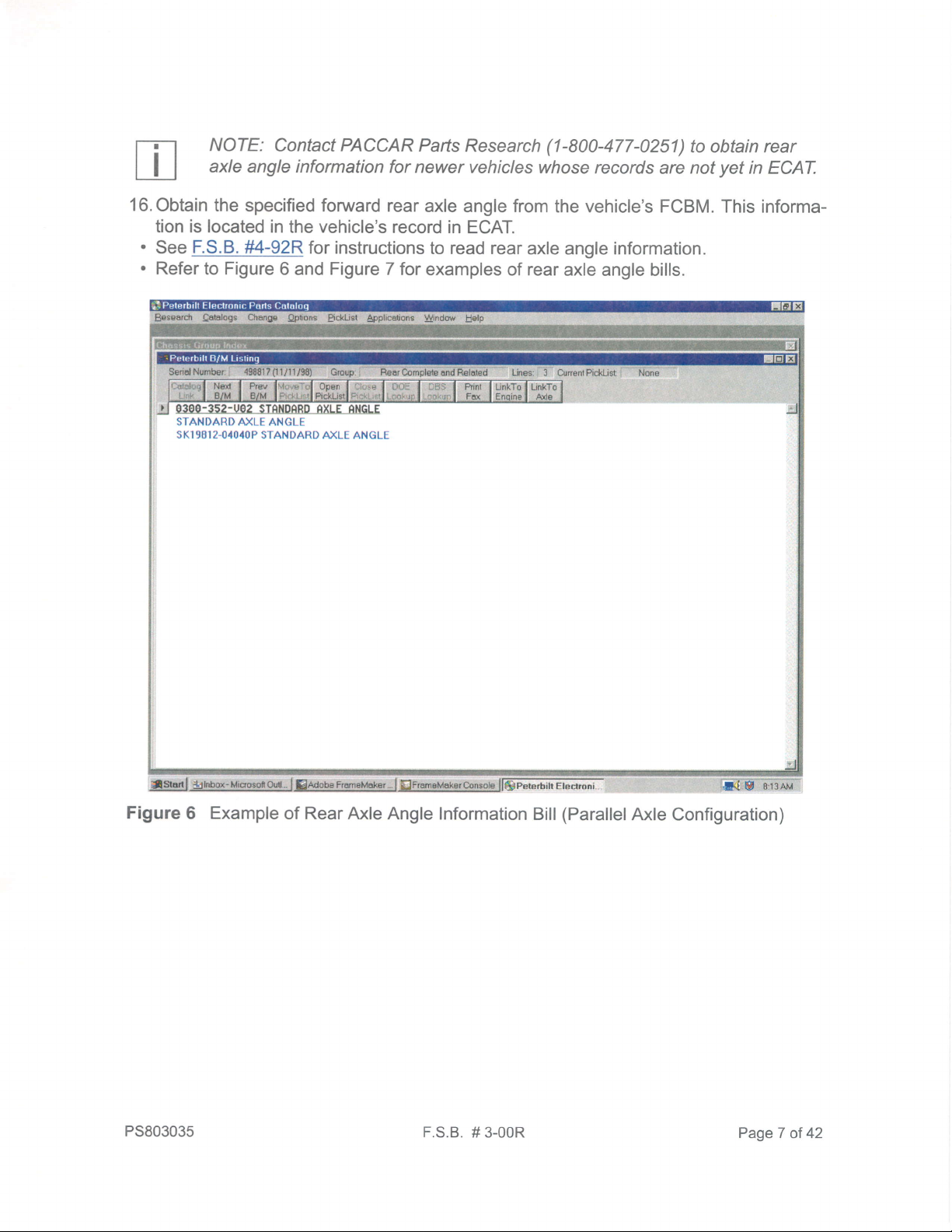
16.Obtain
the
tion is located in
.
.
F.S.B.
See
Refer to Figure
specified forward rear
vehicle's
the
#4-92R
for instructions
record
6 and Figure 7 for
axle
angle
in ECAT.
to read rear
examples
of
from
the vehicle's FCBM.
axle angle information.
rear
axle angle bills.
This informa-
Figure
PS803035
6 Example
of
Rear
Axle Angle Information
F.S.B.
# 3-00R
(Parallel
Bill
Axle
Configuration)
PageT
of 42
Page 8
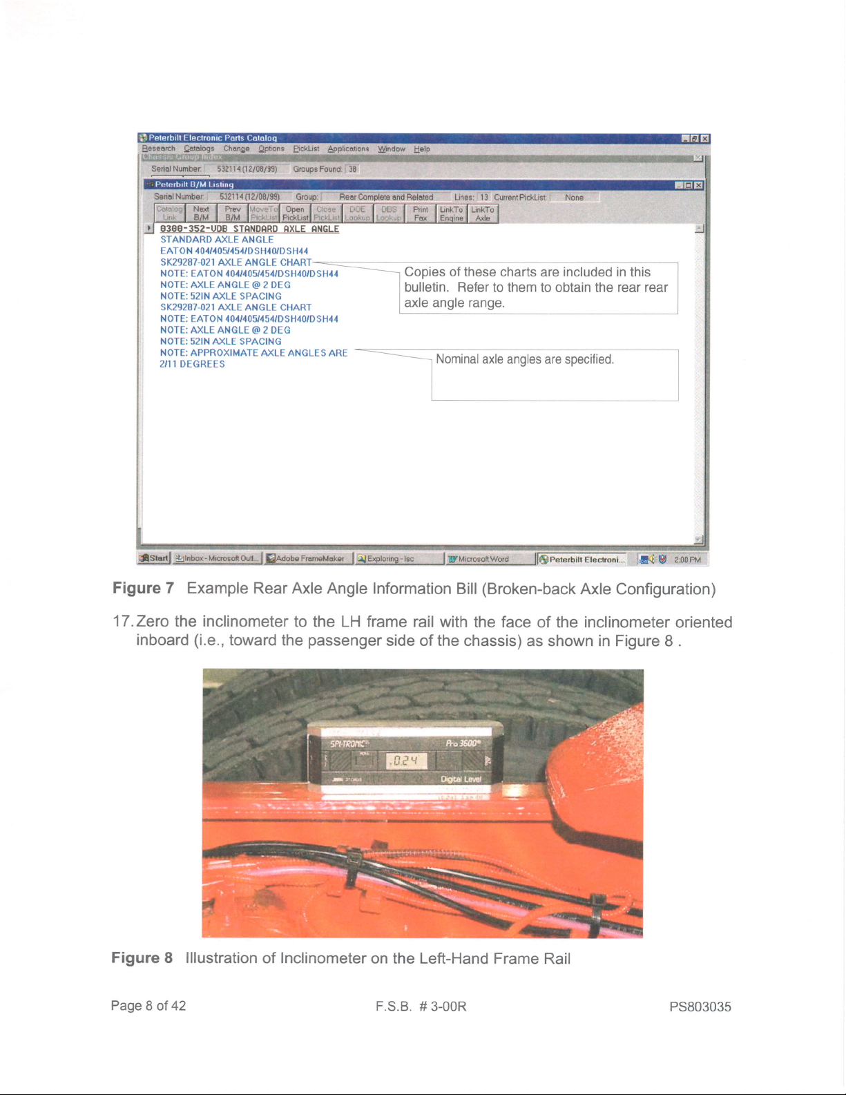
Figure
7 Example Rear
Axle Angle Information
Bill
(Broken-back
Axle Configuration)
17.Zero
inboard
Figure
Page
8 lllustration
8 of 42
the inclinometer
(i.e.,
toward the
to the LH frame rail with
Inclinometer
of
passenger
side of the chassis)
on the Left-Hand Frame
F.S.B.
the face
of the inclinometer oriented
as shown in Figure 8 .
Rail
# 3-00R PS803035
Page 9
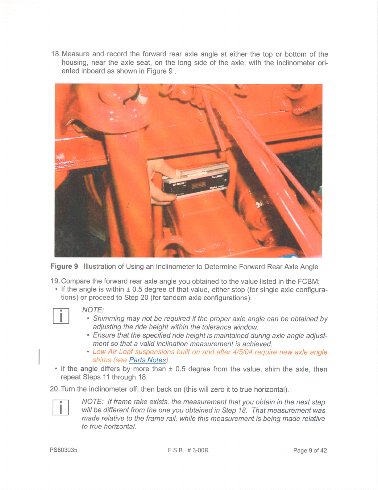
iB.Measure
and record the forwarci
housrng, near
ented
inboard
the
axle seat, on the long
as
shown
in Fioure
rear axle
side of
9 .
angie
at either the
ihe axle, with
top
or bottom of the
inclinometer
the
ori-
Figure
\
I lllustration
of Using an Inclinometer
\
rb
/
to Determine Forward
Rear Axle Angle
.#
l9.Compare
'
lf
the angle is within t
tions)
the forward rear
proceed
or
NOTE:
'
'
.
lf the
"
repeat
20.Turn
PS803035
angle difters by more
Steps 11 through 18.
inclinometer
the
NOTE: lf
will
maoe relative
to lrue horizontal.
axle angle
0.5 degree of
to Step 20
Shinirning may not
(for
tandem
be requireci if
adjusting the ride height
Ensure
ment so
that the specified ride
that a
valid
inclination measurement
|e4s_l'/qteo
than t 0.5
off, then back
frame rake
be different from
to the frame rail,
exists, the measurement
the one
you
obtained
that value, either
axle configurations).
the
within the
height is
to the
proper
tolerance window.
maintained
degree from
(this
on
you
while this measurement
F.S
B. # 3-00R
wiil zero it
obtaineci in Step 18. That measurement
value
stop
listed in the FCBM:
(for
single axle configura-
axle angle can be obtained
during axle angle adjust-
is
achieved.
value,
the
shim the axle, then
to true horizontal).
you
that
obtain in the next step
is
beinq
by
was
made relative
Page
I of
42
Page 10
21. Remeasure
zontal)
and record the forward rear
at either the top
of the axle, with
or bottom of the housing, near
inclinometer
the
axle angle
oriented inboard
as shown in Figure 9 .
(now
with respect
to the true hori-
the axle seat, on the long side
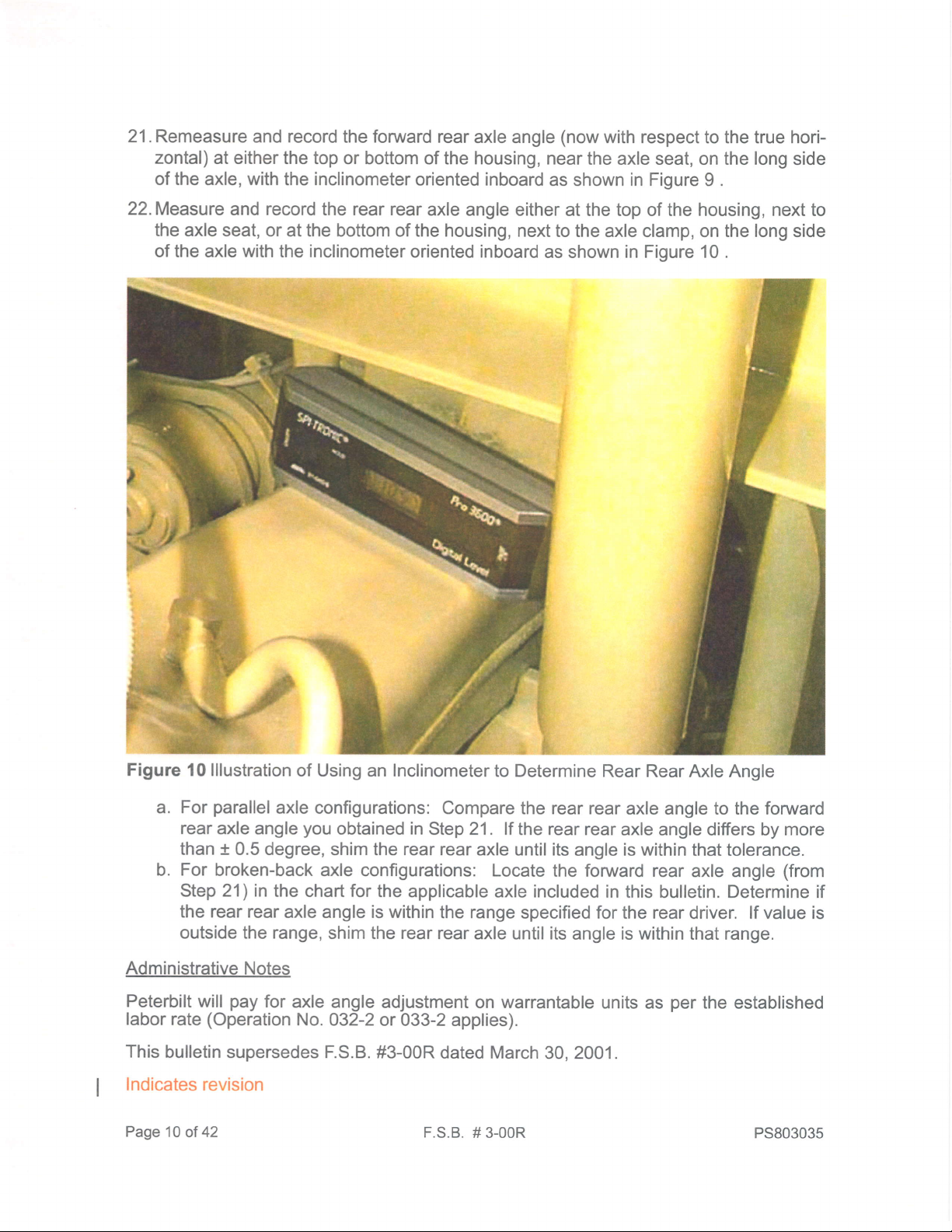
22.Measure
the axle seat, or
and record the rear rear
at the bottom of the housing, next
of the axle with the inclinometer
axle angle either
oriented inboard
as shown
at the top of the housing,
next
to
to the axle clamp, on the long side
in Figure 10 .
Figure
10 lllustration
parallel
For
a.
rear
axle angle
of Using an Inclinometer
axle configurations:
than + 0.5 degree,
b. For
broken-back axle
Step 21) in
the chart for the
the rear rear
axle angle is within
outside the range,
Administrative
Peterbilt
labor
rate
This
bulletin supersedes F.S.B.
Notes
pay
will
for
(Operation
axle angle
No.
Indicates revision
Page
1O of 42
you
obtained in
shim the rear rear
configurations: Locate
applicable axle included
shim the rear rear
adjustment on warrantable
032-2 or
033-2 applies).
#3-00R
to Determine Rear
Compare the rear rear
Step 21 . lf
axle until its
the
rear
rear axle angle
angle
the foruyard rear
the range
axle until its
specified for the rear driver. lf value is
angle
dated March 30, 2001.
F.S.B.
# 3-00R
Rear Axle Angle
axle angle to the forward
more
(from
is within
axle angle
differs by
that tolerance.
in this bulletin. Determine if
is within
units as
that range.
per
the established
PS803035
Page 11
to
s
€
E
s
R
s
8
E
x
a
t
G
f
s
o
E
a
s
.E
sd
.gF
EE
e8
5.s
s*
OG
Fg
RQ
E8.
$E
sg
HR
9s
lu tL:+t
J]
.o
\E
Y
a
F
*b
oo
IJJ
J
o
z
IIJ
JV
ao
a
IIJ
X
ut
@
o
=
I
(L
F
ro
sf
s
s
K'
$
o
t
tr
o
F
t
uJ
lo
o
o
I
@
(\
3
o)
(\l
N
Y
N
a
I
o
t
@
(\l
ct)
b
ol
Y
o
a
c')
o
o
FI
@
(\
o)
6l
Y
U'
(\l
o
o
I
3.
@
N
o
N
Y
o
o
o
I
o
N
(\l
CD
o
N
Y
a
N
o
(o
o
u)
s
(o
@
s
o
@
@
\
c,
(o
o
$
tr
e.
IIJ
o
o
*
@
ol
CD
ot
Y
@
o)
o
o
@
(\l
CD
ol
Y
a
@
o
o
I
@
C\
CD
6l
Y
a
o
o
t
@
N
CD
N
Y
a
(o
o
o
I
@
ol
CD
N
Y
o
(Y'
ro
sf
lo
F
ro
@
{
@
(v)
ID
o
o
{
o
N
r
o
@
$
ro
z
r4t
@
o
F
ol
ro
t!
o
@
F
(\
|o
t
F
o
F
e
ul
Lrl
t{)
to
o
(\l
ol
o
o
o
t
I
@
@
@
(\
ol
C\I
o)
o)
o)
(\l
6l
6l
Y
Y
Y
U)
o
o
CD
$
N
o
o
o
(Y)
r
o
@
GI
CD
(\t
Y
@
N
CD
(\
Y
o
I
*
@
@
6l
N
CD
o)
(\l
sl
Y
Y
U'
U'
(Y)
@
N
o
o
I
I
€
@
(\
(\
qt
g)
6l
N
Y
Y
q,
o
(\l
N
o
o
I
I
@
@
(\l
(\
CD
ct)
6l
C\
Y
Y
U'
U'
@
N
o
I
I
?
@
€
ol
ol
CD
CD
6t
N
Y
Y
a
a
I
a
(!
o
@
N
ct)
N
Y
a
F
o
@
ol
CD
(\l
!<
o
s
sf
a
o
b
sf
I
a
o
t
lo
{
r4t
o
s
t
o
s
z
F-
@
F
o
(\l
$
ro
@
CN
o
(\l
o
ro
(r)
(0
z
o
{
N
F
(o
IrJ
{
(o
s
o
(o
s
z
o
F
ul
o
K'
(l)
(v)
o
o
I
I
I
@
o
(\l
N
o)
ct)
ol
ol
Y
Y
U)
a
q)
$
N
o
o
I
I
I
o
o
(\l
6l
ct)
CD
(\l
ol
Y
Y
U)
a
c)
@
(Y)
N
o
o
I
I
t
o
ol
CD
6l
Y
(t,
ol
o
@
(\l
o)
6t
Y
o
(o
(\
o
@
(\
o)
(\
Y
U'
I
o
(\t
o,
o,l
Y
U'
N
(v)
o
I
I
@
N
o)
ol
Y
a
(o
o
I
I
@
(\l
ct)
N
Y
a
ut
tr
f
o
uJ
o
o
tr
(L
lrJ
J
o
z
uJ
X
tr
o
lr
(Y)
(v)
q
o
o
(Y)
o
o
lrJ
o
z
lrJ
t
uJ
lr
uJ
t
ui
F
o
z
PS803035
F.S.B.
# 3-00R
Page 1'l
of
42
Page 12
o
o
@
N
O)
c!
Y
@
q
oq
tu
oauJ(9
<>z
rtJp<
I
E6t
isu
uJxz
E<<
llJ
n
F*
aul
rulo
<>z TlTl.;
wp
t
^X.
tgdl-lc
uJxz
t
<<
e5d
\
o
o
I
oq
1\
o;
o,
TU
q
c?
o
o
q
l'
I tl
9lu?iQ
-lFlF
(olrolto
<
ci
lci cj
Flr
trl] 1 I
ir tF
l-l-l-
lul
ll
ol-i*
I
I
q
o)
ci
-
q
F
t1<+l+l+
T
o
I
nl
o)l
i
o?
o)
I
u?l
to1
li
atc?iq:
;l;l;t;
a? ollr
a
ooo;o
FFFi-
tf t
o?oq\q
ololo
-1-1-l-
c?inlq q
ololo]=
o
qq
5rE
3ie
qu?
oo
-l-
\oq
$$
Iq
oo
IE
'l'
qiq
o)
o)
.,I;
r]'
o
o?
o,
n
o
o?
{
q
c
s
e
5
P
c
o
o
e
x
G
A<
o
G
f
c
o
r<
Q
a
€
=
-Ea
or
G.9
sE
u?
c?
c\l
N
q
q
(\
o
c.j <'i
n
N
a
o?
C!
I
a
oq
c!
(Y)
tu
(ur(,
<>z
VNfr
=o
isU
uJxz
t<<
e5d
sxz
tL<<
?#
o9=
z
I
c.i
N
I
c\l
I
q q
\
cin
(9
CO
q
c
N
N
q
q
rO .q
(o
l.()
(f)
c.j
fiqle
(t
c!
d
<>z
ilEHfri
;
H
9-22
$EEII#
$I
fi E =*
E3t
e EE
"ffU
V_8fi
tsa
|,J'jxz
tr
<<
u.l
o
ex
<>z
"frU
lllt<
0lE,t
cf)
I
d?
c!
I
N
N
IU
@
\
c.i
N
c.i
q
o?
ll)
s
I
q
o,
\f
c.j
<'i
oi
q
ol
q
c!
oq
s
oq
(9
q
@
o?
c
(a
N
ic.i
lF
Y
I
I
q
q
ol
l"c
N
N
l=
l-
I
u?
N
a?
N
\
$
\
I
u?
(\I
a
N
q
$
q
(f)
in
lC\l
u?q
NC!
u?
v
q
(f)
c?
N
n
$
n
CO
oq
-
o?
@
o
c;
c?
t\
@ o?
c.j
\jq
c\r
ic.,l
\le
==
I
ol
:
c!N
a
.f
s
c?
a
(9
cf,
f-
I
N
c!
FS
5.S
qq)
oI
(aG
EE
EQ
E8.
(o
u?
N
u?
I
.PS
:s
6c)
f,3
lrJ 9
c)o
=e.
o
o.i
q
N
ol
s
I
ol
cr)
sqs
o?
o?
oq
q
q
(9
o?
C\
o
\
(r)
(f)
(o
cf)
I
q
N
oq
N
I
q
\
N
N
n
;
I
I
q
u?
\
N
N
N
Page 12
a?sc!
lu?
ls
o
d ciNo
a
s
F.S.B.
iri
UJXZ
t<<
siglFaE
f*?
of 42
\f
c?
o
q
s
s
n
lu?
oo
#
o?
o?
(v)
q
\
o
3-00R
oq
(o
oq
o
(o
ri
qr
q
(9a(9
c! cf)
\
(Y)
n
(oa?(o
q
(f)
u? q
Y
<.i
c
(f)
(7)
N
oq
\
PS803035
Page 13

{99
?
uEfl 3
tsHl.
H{?r.
si9;
rJ-<<
t:
I
o
rq
o
io
z
c
s
c
N
I
q
N
o
o
@
c!
o,
N
Y
a
tr*U
<>z
'"8fr
I
?,s
rt
i
;
q5H
tu
(r.uO
<>z
'"8fi
ee
r
fr5
9i2
*5d
wxz
t
<<
IIJ
oq
N
oq
ni
:
o
I
$
o?
o?
s
\
N
\
(\l
N
o{
o
ry
o,
\
o)
d
I
I
I
:
o
I
o
oi
o;
q
u?
o,
O)
q
r() 1r)aro
qo?
-O
TT
qo?
OO)
C.l c?
st
oq\
5t
oq\
oo
@(o
c.i c.i
TT
(o(o
I
c.i I c.i
o? oq
oq
o)
?9
oq
o?
oq
@€o
@
a?
a
o,
o)
o,
u?q
lo tr)
I
oQ
\;9
o olo
t5Y
oe\q
o)
o, o,
au?q
s s]s
rrq
I
u?q
(f)(f)
qna?
NN(\T
T-;:
q
nlc?
r r':-
q
oq
Io?
N--
(O
tO
F-
++"
(O
tO
f\
ddd
c!rq
o) o) o)
\qo?
lrjtolr)
u?na?
ooo
:l:5
u?na?
or,o, o)
gorco
3"tot
lco
l\
$
9rt
n
I
a
o
c!
r.r
NNN
ITT
Nrr
---
IT
\qq
R
O)
Y
@
o?
Y
q
q
I
o
e
R
o
o
e
x
G
f<
o
$
s
s
c)
.r<
e
a
=
P:.
te
E.e
ss
nff
5.S
qo
o>
(/)G
Eo
EQ
oF
(/J \<.
d)e
SE
:=
6a)
)3
Lll O
c
tl'
C)o
=e-
c
F*?
N c.j
qc?
NN
a
(\l
1rllq
*lN
$gEilgE
c? e!
Y
S
ro
c.)
s
-
s
n
(7'
o?
(f)
fg
ZE
fiE
<>z \
"ffU
uJt<
E^t
{sdl"
uJxz
E<<
p,ag3[iF
;t:ls
PS80303s
d
9S
TT
(tN
c.i c.j
o
t\ q
d
C\l
,a?
oio
:qo?
\t \t
557
:qo?
,(f)
(f)
lr)
(o
(?)
.t |r?
o
F.S.B.
\q
NNo?C\l
o?oq\
(f) (o
(fJ
(o
r:5
o?,0q
c!
NNN
a n
(f)
q
\
i09
o
oo
# 3-00R
\
N
<.i <"i
o
J
qu?
a
cD
l(f)
I
EE
n
NN
N
d c.j
Oir
o! c?
--
a
(f)
n
N
O)
NoqN
("?
I
N
a
c!
(f,
d
c.l
N
oi
q
\
C\I
N NnNaN
rn
o?
o?
c
N
N
I
q
o?
-
N
oq
o?
\
Page
13
42
of
Page 14

(o
o
o
@
N
O)
N
Y
U)
q
a
ftggi;
HE# s
o
n
o)
(?)
c!
o
c?
O)
c!
o
o
q
c!
o,
O)
o,
n
o
I
a
o)
oq\
o?
q
?
??
oq\
o?
o
@
@@
ot
e
o
s
P
o)
tr!gl:
(r<<
-
UJ:
s*e;
I
c?
ctu
(trl(,
<>z T
UEtr]E
iSdic
uJxz
'osl-i-
e5d
t1Z.
r -
o o o.o
o F N
$ $ls +
ot
d
c?
=;
P
q
oi
o!
ro
o{:
TT
Nr
cio
r c
- -
(o
@
o;
d
t-
F-
oi
oi
u?
9
r^r)
lo
O rd)
;
ici
4c
oo)
qn
oo
-,-
$lo
$$
(o
oi
(0
lo
oq
o
0q
o,
a?
o
q?
s
lr)
;
i"o
\
rO
\
o
\
o,
qq
oo
-l-
\q
ss
1'-
t\
ot
a
O)
tO
(f)N
oi ot
o?
lc
1r)(o
q?
o
q
o,
-i
q
s
o
o
q)
x
o
A<
o
o
s
q)
{
e
a
S
'=
$e
'=o
>'E
YS
o
z
(,
z
o
(L
3'
JIY
x
(/)=
t F8
?
E ?
{ 9 3
E I
B
P-
Er
=6 V
5:
3?'
5P
qlp
I2i_
s5
{f,
fr
Hdi2
'
i *4
il
#
$4
=;
e
eE
r'
E FE
f.' B
ag
tsu
uJxz
3'
t
<<
e5d
sxz
tL<<
Cu
dr!(9
<>z T
pEfil3l:
*sH
UJXZ
E<<
f;i2lrlr
<>z
"ffU
PEfr
trtrJ
<fo
|Jlxz
(r<<
reiHSHaE
F*g
c.i
":
(o(orf)$
----
-i-l-l-
IU
q:qc?
(9 (fr (f, (t,
o?
c,,t
=i"
N
- -
'41
I
-t
s
I
a
cr)
u
o?
(Y)oq(?)
q
o ci
cri
:
o9
N
-;
ol
c?
s
d?
(r)
q
N
I
c
\q
NN
-;Y
\q
:=
o,l
c!N
T
C\t(f)
c.i c.i
c?
nl
$t
5Y
a? ol
(Y) (Y)
it\
o
c.j I C.j
q
o o
ol
o?
o
r
oq
\
I
I
oq
r\
o
o
c?
c!
=:
oio
(r) (f)
q
u?
N
N
q
q
q
e.i
N
u?
a
N
N
..9
sl$
5t
.:q
(Y) (r)
-lI ru?
(?rid)
a
ou?o
q
o
..
(o
<'i
a
c\l
a
-
q
N
q
s
q
cf)
u?
(Y)
q
o
u? u?
i5
u?q
qe
::
\q
(Q
i(Y)
c?
n
c{
N
o?
a
oq
o?
0q
\
N
N
o?q
r(o
d)
t'l
qoq
NN
-
l:l
nc?
(a(r)
\oq
oo
a
T
n
o
O)
ci
l
o,
d
c!
c!
I
ry
f-
-l
o?
N
oq
I
@
N
c.j
o?r
o
l-
(')
6i
N
(f)
q
\
f-
qq
(o (o
TT
qq
NC!
l
.:q
(?) (f)
..
c!
Efi
5.S
s*
oo
EE
EE
E8.
.gs
='=
6q)
f,3
HE
oo
=g
u?
a
q
n
(\t
N
o?
e
(r)
N
(r)
a
c?
c!
c'j
I
I
a?
oJ
c.i
N
N
0q
N\NqNqN
q q
f\
o?
<'i
N
I
I
q
c
N
n
c{
Page
14
of
42
F.S.B.
# 3-00R
PS803035
Page 15

o
o
@
N
o)
N
Y
a
q
c
€
q
S
R
s
o
o
e
x
G
r(
()
$
a
o
{
Q
a
I
c!
o,
]Y
llo
q
o)
I
(0
d
rr)
ri(ori
lO
ot
,$
at
q
o,
(t?
o
c?
o)
nYc?q
o);o) o) o)
++c6cf
ctdoid
i
lii
oq
o?lq
@lo@@oi
t elq;C
|I) |f)irol@
qc!
oo
YY
c!
or
1c\|
10)
\
o
q
q
cD o) I ct)
I
414 *
-i'-
c
o,
.t
u?
o,
o,
c! a?
lo lo
d
\
o
\
o)
clr
I
c?
ls,
c
tu
o
o
o,
rO
ot
q
ro
irffU
<>z
-"8fi
lru
E5d
wxz
t<<
FX?
I
dluO
<>z
'"8fr
c
ut
(7)
ci
q
s
{su
|JJxz
G<<
o5d
sxz
tL<<
\\
o) o)
I
\oq
s$
E
€e
E.e
sE
o
z
o
z
o
o_
?,
duJO
<>z
'"-Xfr
{su
uJxz
f,
(r<<
EUJ
u.l
q
(o
o
:
*o4
q
IU
'ur
III
o?
q
N
c
s
q
(o
u?
cf)
q
o
(Y)
a
N
a
T PE
?
q
{ 9 P
E P
3
E;
HF
E5
;3 X
9b It5 a9.
E= Z
=g nv
nig7tr?F
wte
-
f
t
H
::
z.N(fr\f
q
2I
ft
Hdi.42
F
*fI
g
H
I
P
F
9 FE
q5
J
vrrl
E
f;*g
lC
E=
<>z
s5
"frU
PEf,
{F
{su
|dlxz
(r<<
si9
r!<<
=B
g:
5s
<>z
"frU
lrJt<
Ee,t
*ga
uJxz
t<<
F**
q
u?
:1i
Tlr
q
u?
a
la?
o
olo
-l-
q
qoq
olo
c.l
c?n
(t,
ta?
co
l
ic!
(9
:
N
<'i
a
c!iNiN
ql;I:
-l-l--
co
ir
c.i c.,i c.i
\\
(Y' (t)
lc)
TI
oq
\\
c!
i
qq
ln?
(') (Y)
cf, iv
oci
<o
lN
ol
-l-i-;
l|l
rNCr).(f
c.i
o?ioq
o
55
o?
6t 6l
ll-
n
(?)lc')
'.:o!
OrO
c!
c\l
o
\
o
.r)
c't
e
N
q
lo
u?
N
q
(f)
q?
N
ctj
rq
o
qc
tt
cg
oto
o
-l-
q
qu?
o
oo
q?
(f,
5i3
ocic
o?
o)
E i]I
o
o oio
-l-i-
<'?
n
:l::
q
\
(\l
N
u?
u?
(9
(V)
u?
q
ol
N
q
q
(r)
(9
q
\lq
o
o olol
ol
o
I
O)
ot
n
o
(e
\
o{
ic?
ll
oq
io?
NiN
c?
a
(r,
c.)
I
rl
n
ic?
(\l
N
t
o)
loq
c.i
iN
o?
lF
Fg
5.S
co
oI
(a$
Ee
bq
E8.
fr:
f,3
HE
9s
rO
c!
(Y)
I
N
c.i
\
N
q
q
ni
I
q
N
u?
a
N
NaN
c\ c?
N
o?
o?
N
I
n
(\l
I
I
oq
c?
N
q q\oq
(r)
I
6i
c.i
.:
oq
q
\
\
N
\
c!
N
a
N
N
N
I
I
q
u?
\
q
c.l
N
ni
N
o?
PS803035
F.S.B.
# 3-00R
Page 15
of
42
Page 16

O)
O
o
@
N
o)
N
Y
a
qq
u?
\
@
I
UT
ur
u.l
\
t-
C\l
@
o
ri
u?
O)
u?
o
"P "9
e
lu?
f*lF-
-1;
@@
I
lc!
ro ro
u?
n
o,
O)
lJ)
n
AC;
@
<>z
"frU
urt<
t6t
tsu
wxz
(r<<
e5d
t14
d
trruO
I
<>z
axfi
n
@
a
F-
o?
t*
(Y)
d
ot
(v)
d
c?
q
Y
@
o
@
I
c?
q
a
N
t-
t\
oq
1\
o?
t\
F-
l\
u?
q
a
lo
lr)
ro
q
c!
o;
I
O)
I
I
I
q
N
@
d
@
d
t-
q
l.-
\
ro
q
o,
o
cd
I
I
o)
d
F-
I
q
o?
(o
F-
q
n
F
f-
o,
a
1l)
ri
o? oq
?09
o?q
l\ 1\
o?
r\
o?
(o
Y
t-
(o
q
c
s
E
5
g
c
o
o
o
x
G
r<
o
G
a
s
o
.Y
Q
a
I
€
q
o
tsil
|,J'Jxz
(r<<
F*eis
o)
o?
o,
@@@\@q@
c.lsa?
+
lr)
@
q
u?
R
sf
$
9
s
r(r)
rJ)
*
@
d l€i
0q
o?
\
rif
\t \t
E
€e
E€
o
z
<>z
o
z
o
(L
aa
IIJ
iua*
b
?
E ?
E E
I
*r -
Er
*P
E5
5#
p-=
3Q
qlp
I
fr
Hdi2
fi
il
i i4
g
H
? I {:
E
X
z_
9
fr u
"fiU
uJ;,<
E6E
{su
uJxz
UJ
t
=u
Ft?
z=
rffU
<>z
UNfr
ti
tsu
|JJxz
(r<<
E4
e5d
sxz
r!<<
=g
HE
FE
ag
<<
OL
uJ
E
o
rlf
uJ
J
X
ul
o
z)
t1
J;
ol
zl
a
o
a?
o,
oq
o)
o
(9
I
c;
@
cj
q
(\l
oq
N
oq
c?
N
c!
o
c\l
o)
t\
ot
<'i
q
q
o
u?
o
c.i
\
c!
\
c!
N
ci
I
I
c!r
oo
5T
q:
o) o,
\le
o,
rya?
(Y) (Y)
clc
-lo
Yll
o
o'ol
ro
ctao
o{
(\l
q
c!
I
q
ni
c\l
o
lo)
io)
ni
u?
N
u?
e
N
a
o
ol
icq
?i9
olloc
I
@
lco
ct)
ro
nc?
ot
o, o)
u?
$
lq
(f)
(')i(')
elc t
oio o
Ti5 T
oq
tog \
o) o, o)
(?)
c?lc!
ci
o10 ci
qiq
a
N
*i*
I
nc?
N(\l
irl
lc?
a
-l-
I
oq
o?
i
i
FF
l
I
aq
o10
siHlIeF
6i
c?
aq
(o
o
I
\
\q
o,
I
??
\
\q
@
@o
o{
N,F
O)
oi oi
1\ @o,
(?)
to{
q
o
oro
q
q
;\t
io)
o)
o,
Qor
3oi
t\
oq
c.i
NN
C\l
I:
NN
N
I
cJ
II
I
@(o
\
T
@o)
\
oo
o
o?
qo?
NF
5:
qq
FO
I
qn
=:
q
oq
a?
\
\
o
ry
c?
efi
5.S
t*
oo
Eo
IE
E8.
.9s
l=
6o
f,3
HE
9s
q
q
u?
u?
o
o
;
a
I
a
Page 16
of
42
F.S.B.
# 3-00R
PS803035
Page 17

o
@
N
o)
N
Y
@
q
o?
q
:
tu
(9
(
r.rJ
<>z
HE#
isa
ulxz
E<<
e5d
t14
I
t
uJ
t
t
llJ
OL
t
UJ
t
o
uJ
J
X
c
ci
o
II
(o
u?
o
o
e
1r)
d
o?
I
o?
o
n
q
$
co
o?
oo
cilcil
oq\
T]E
o,
o) cD
io,
I
c),Nl
nn
oo
cjtoi
F-
-l-l
c!ic?ln
tol.r)ro
u?nn
\
;i;i;
qialn
\
o
ooo
FFF
q qlq
Flolo
(',$
N]
s.$
rl$
r..-
i
tl
l
ll
qctloce
ro ro]lollo
i
fT
q
u?
ol
s
(.)
l+
dci
5T
n
la?
l'l'
-l
oq
lo?
o)
o,
ro
c!:
FF
::
oir
oto
*;.
oo
oq
o?
st{5l
a
o,
@
q
(o
a?
c
o
E
s
P
c
o
o
e
x
G
{
()
G
f
s
o
A(
Q
a
s
E
€e
E.9
sE
o
z
o
z
o
o_
?,t
*a4
t FB
?
g
I 9 9
E
3
q:R
8'2=
?
q
ft
Hdd42
rai*E*
il: u
3?i
5?
r,ix3[er
g
rg
E EE
fr u
ag
51
IE
<>z
"ffU
axfi
{st
|,J'Jxz
(r<<
F*?
<>z
"ffU
UNfr
E5d
uJxz
c<<
e3d
9XZ
tL<<
0t
uJ
t
o
3
Lr
q
C.,l
q?
c.i
c
(v)
a
(7)
a
N
o?
N
q
N N
o?
s
o?
(')
u?
N
q
o
N N
(oc!(o
a
I
a
(\,1
o?
6l
oq
.t
oq
(9
q
N
I
u?
c'j
I
c.i
oq
N
nlNc?
\
*
\
(f)
.q
c!
I
9
o?
c?
(Y)
q
(f,
I
c!
N
\
NqN
NaNqNqN
ili
: 9 iu? lu?
\
|.
$
I
1\
i]EEI
;
)l(o <D
.FTF
t'l
c!
{ rl9l9
I S
*
-t--l-
tlt
lisqq
)lo
c;
c?
<q ior i-
N
ni c.i c.i
TTI
-
ocloq
:::=
.tlu?lel\
-l-l-i-l-
c.j
d
c
c.i
N
u?
(\l
9i*l$
rr+
olo
l\t
o?
N
o?
Y
N
(f)
\ c
a
o?loq
o
\oq
oro
0q
N
oq
a?
N
\
icq
NN
a
v
I
l(f,
T
u?
c
o
cri
oq
c.i
c?
$
<.i
o
c.i
q
ng
c
(\l
c
lo
a
(f)
\
N
\
q
(\l
q
N
c.l
c!
s
v
I
c!
(Y)
r\
c.i
CD
o
o!
(')
\
cf)
q
q
s
+
s
I
q
q
(Y)
(f)
lr)
u?
q
(f)
(?)
d
c?
c!
I
5.S
qo
o*
oo
Eo
BQ
E8.
ES
:=
6(I)
)3
HE
9s
q
N
\
(?)
(?)
c'j
q
\
\
N
N
N
q
(f)
I
c.i
c.j
o?
PS803035
F.S.B.
# 3-00R
Page 17
of
42
Page 18

N
o
@
N
o)
N
\<
@
q
q
UI
ET
IIJ
u?ac?
o
ooo
q
4lt]4
ct
'1'l-
9orco
ci
Sotot
q
:ic!ic?
lr)llo
r.()
c?
c!
I
I
(o
c\,!
ci
o
0q
\
o
o
o
I s
EU
Er!Ct
<>z
HEfl
Esu
wxz
(r<<
e-,td
5XZ
r!<<
I
<>z
"fiU
-"Xfr
{5d
uJxz
tr
<<
f**
il
rf)
c!
c!
o
o
(o
\
o
o
(r)
c!
\f
s
o{:
olo
T]Y
c!
ir
rl-
I
f-@
oi
a
lu?
lr) ro
q
c
q
o
o
ci
u?
a
o
\qtrn
s
ot
I
ci
CD
q
o,
(o
rr,
o?
o
o,
ot
R
o
(q
r+
I
oro)@
q
o
q"?
o)o)@
I
q
dccid
o)
(?
olo
o,
oidot
ocqq
\
rr)
to
oq
\\
o
o10
I
5lr
oq
F-,N
CD
o
c?
c! c!
o
oo
oq
\
$
sr3
li
-
rrl
ro
l(o
io;
I
o?
c
o
E
E
f
g
o
o
o
X
G
\
o
G
a
I
s
o
.r<
Q
a
c
'=
$e
E€
o
z
o
z
o
()-
?,
g,
* oe-
h P5
?
E ?
t
E 9
E
f;= e
n6 d { }#
[3
il: frE
E?i
(etfi
3X
H
=
z.N(f)t
qlp
Ei
8
55
P
9
{E
ft
Hdi2
{
+5
E
=$
fr
rb
EE
E
ufi
=
;E
u 8F
q
(\t
<>z
"fiU
ru;7<
ta,d
{5d
uJxz
0a<<
a5d
sxz
r.r<<
dI!C9IN
<>zi5
uEslS
{gil
LlJXZlc.l
E<<i-
e**
<>z
"SU
lu;,<
E6t
i5d
|,J.lxz
t<<
e5d
=xz.
L<<
c.i
I
TIJ
q
q
(o
E|r|]C2
"
r
q
$
1r)
d
IU
q
9
o
o o
I
q
u?
e.i
o?
N
q
na?
NC!
-F
:
NIN
n
$
n
(")
o?
(O
q
c!
I
c
q
C\l
(o
oq
N
0q
le!
c?
$
(f,
0q
(o
cJa
oo
o?
I
ct)
cj
n
(Y)
<.i
\
N
\
c!
N c.i
c?
a
c!
NloNqN
c?
c\l
!+
s
c?
c\l
(f)
(o
oq
\
(v)
(r)
a
ou?o(oci
ns
0q
0q
q
qs
\
I
\
o
q
(o
<.i
a
N
R
O)
q
s
c
(r)
u?
(7)a(f)
:=
q
4t+
o
oio
-lqo?
:
FO
t\
alq
(7) (Y)
<'i
I
a
e
C\N
N
I
rl
c?
oq oq\
oglo?
\
c{N
N
q
(f,
ci
I
oq
o?
c{
N
c?
t\
oq
o
o
^,1
c.{
\
cf)
5
\
N
F'
ry
(Y)
o?
o
\i
(o
:
\
c!
N
c.,
q
(o
q
n
(f)
(f)
(e
I
u?
R
(\l
N
N
l
o?
c'j
c.i
N
i
N
I
0q
@
o
c;
c?
c?
q
R
(9
q
u?
N
N
q
u?
q
N
+
I
ai
q
o
n
(e
n
c!
o)
(\l
s
5.S
t*
O(u
EE
EQ
E8.
fr:
f,3
HE
9s
o{
c'j
I
c?
oi
(\l
N
oq
N\N
(o
rr,
c!
(o
ci
ai
I
I
c!
N
c.i
o.i
q
lf)
\
c!
c!
N
t-
@ o)
Page
18
of 42
F.S.B.
#
3-00R
PS803035
Page 19

(o
o
I
@
N
o)
N
\<
@
2
o
z Fo
3
,q
otr
q
:P
isu
|Jlxz
c<<
oui
en
<>z
"ffU
uJF;<
tF,t
a
{su
wxz
E.<<
oul
tx
<>z
"ffU
pxfr
IU
qq
09 09
q
lu?
F
Ilr
I
+
I
eO
dci
q1:
ro
[o
cl
ol
ct
oi
(o
oi
q
o
q
o
o
o)
!o
oi
(?)
I
a
co
I
n
N
o?
l.*
c!roa?
(f)
N
$
++
ol
q
o,
o
o?
I
q
@
o,
u?
n
o,
o)a?o,
c\.l
a?
(D
(o
c?
@
c?
t-
@
t-
ro
c?
@
I
(Y)
t\
q
t-
.q
ro
T
s
q
o,
I
o
at
a
(Y)u?(Y)
ol
:iqce
090P\h
@
d
I
I
(\l
rqo?cq
1\
F-
F-t'-(o(o
(o
.1,"i.
\
l.*
F-
t-lF-it- t-
u?
q
\oq
ro
rO
lo ro
oq\
09109
oc
t-
qtq
s
(o
\
\
o,
o,
ot
I
I
I
q
\
\
o
@
@
(\l
C\l
o,
o,
q
\
(o
(t,
l\
lt-
I
i
oq
*\s
u?
?i?
u?
@o
qq
o)
oq
(t)
cle
rot(o
I
q
i0P
le
lr*
O)'
+
I
tu?
iu?
o,
o?
(f)
I
i;
q
c
o
e
P
c
o
o
o
x
(!
]<
o
(u
f
s
Q)
.Y
e
a
s
i
IA
sa'
oc
E.9
sE
ns
5.s
s*
o$
Eu
EQ
88.
.PS
==
6o
f,3
€o
c;
oq
o,
c?
N
a?
oq
c!
o
I
q
\
o
o
I
q
\
o,
O)
a
(\l
a!
N
oi
q
I
q
\
a?
n
o
o
F.S.B.
u?
a
o
o
U?
a
O)
o)
e
o?
o
o)
u?
NqN\NoqNo?6l
q
q
N
N
I
q
q
l.c)
q
u?
q
o
o
# 3-00R
o?
o?
o
* eg2:=
fo
2
ft
F
Hdi2
I=
<>z
"frU
aN{
{sil
uJxz
(r<<
$*?
$iEHfifi
i32-efE
fiP
f, I
uaHlIeE
ag
t
(r
TIJ
-"X
t
lrJ
J
uJ
X
E
u.l
o
EX
o
o?
o?
o)
o)
a
oaoa?oc!o ci
c
N Nc!Na?N
uac?
c.,l
N
O
z:l:
trl:l:
lF l-
uJl
I
dlele
zlFl-
-
<l-
sfl
ol-
O
=1"i"
PS803035
c?
c?
o)
oq
o)
o?
o?
o
n
\
o
I
c?
o
I
a?
O)
@
o)Iro)
oq
I
oq
o
a?
oq
io?
o
e!
o
I
c!
o,
1\
T
\
o
Fl
qi
:
o
I
q
\
q
\
o
N o
q
u?
u?
c!
a
n
o
o)
o
a?
n
n
o
o,
o
n
HE
9s
c?
q
a?
q
o
o
@
t\
o
o
u?
q
C\l
q
q
o!
A
o
o
(o
r()
t\
o
o
o
@ o?
\
Page 19 of 42
Page 20

lu
t
(rIU
o
z
E
HE
{s
[!x
t<
t
EU
aE
fts
r
o
@
N
o)
N
Y
a
I
tux
t<
u.l
o
rx
rffU
<>z
PEfr
iga
a
r.lJ
x z
E<<
6
ei9
Fd
rr<<
g
?*#E
q
I
2
fr=it4:
fr
Hdi2
x=
<>z
"frU
uJ'
4
EE,t
{5d
|JJxz
t
<<
oul
FX
c!
o
I
c!
l\
\
F
o,
od
I
o?
F-
s
d
+
\
o)
\
co
N
CD
qir
(o (')
aa
oo
5T
u?
d)lo)
9or
9ot
9rl
NN
la
\
o)
I
\
@
o{
o,
o? 0q
e
@
hh
I
q
o? oq
(ol(o
r\
I
u?
nc?
l\ l\
t-
1\
le
0P
at
q
\
F
F-
c!
@
i'
I
'if
a?
r
s
i.+
rQ
q
s
o,
o,
o,
I
I
q
.q
u?
o
@
@
o?@ol@oq
:i9
o) o)
C.,l
a
(r)c?(r)
(Y)
q
c?rc!
oio
o
TITII
O) O) iO)
oq\\
o orlo,
c!a?n
NC\N
fi38fi=g
g
@
o?
c!
oci
o?
o
=
i@
io
a?
o
iF-
:
\
a
o
c.i
<>z
"ffU
EE
3i
trP
t' u
;iH3[efr
-"8fi
iE
ag
%5d
uJxz
t
<<
ou{
EX
N
q
:
\
\
1\
1\
l'*
\
<ri
@
c\l
q
t-
F*
clc
? 109
u? u?
t- t-
L
qq
-l-
u?
ig
$tt
a?
a
o)
o,
I
c?
n
@
@
@\@
u?
q
(7)
(r)
o
ct ioi
ci
-io
qd
ct)
oi
q?
u?
o,
o, o)
(o
u?
c.i
N
-I
qu?
q
Tli
q
q
o
loo
rf)
q
ci
I
q
1\
q
(o
F-
Y
@
n
t\
o)
F-
\
s
q
o,
nl
@
\
(Y)oq(Y)
io,
I
l.c
lft
lc.i
lu?
\
o
q
F-
u?
(o
o
F-
c?
oP109
a?ic?
l- f*
@@
*l*
oq
s9
:9
o) o)
I
tl
-Q
@@
qu?
@i@
o?
9?
o) !co
did
a
cD o)
oqq
NN
nc?
'T
nc?
o10
oq
o
u?
t\
u?
(o
q
1\
c?
f
o?
o?
(t)
0q
lc?
o)
o
q
(o
q
n
t\
I
n
(o
s
o
E
s
g
c
o
o
e
x
G
f<
o
o
f
o
e
a
s
'=
€e
E.9
ss
ng
5.S
sc)
oE
(aG
Eo
EE
E8.
.Ps
:=
6(l)
f,3
l-rr O
las
9s
^l
a
(9
q
o?
I
-
o
I
e
o
q
O
q
o,
Page20
of 42
F.S.B.
# 3-00R
PS803035
Page 21

fi
U;;
t
>Z
UJ
t
Efl
I
u|
t
5do'
uJ
>(zco
E
oul
=x
LL<
r
N
o
@
N
o)
N
Y
@
I
o
z
(9
z
C)
ftg9l?
uE#ii
is
lIJ
X
t<
a?,
5.&
I F8
3 v 1P
z
* =tl-
qI
?r?
]C\
s
-
in.
il
\q
@@
tc\lc?n
Y
|r)rr)r.c)lo
lo
rqo?oq
ooo)o,
::oo
r9ciaj
o) o)
r
q
s
s
IF
c?n
st
qroq \ q
??q09
o?oq\q
F- F- t* F-
ilr
ac?c!:
@.@@@
q\oqq
q
|r,
ro
ro
i.
(O
1.-
9e+e
\qu?u?
o1@@@
q
u?
1\ cO
t
s
ss$
/i
rQ
(t,
rr)
tf)
(n
u?
@
F.
d
q
(o
ro
rO
c
.9
q
R
c
o
o
s
x
G
r<
C)
a
s
c
c)
.r<
e
a
'=
-<
1?
O)
ie
E.9
sE
FS
5.S
so
ox
oo
Eo
TE
E8.
e€
:=
6q)
f,3
fr ?
*
X
5r
I
n P il
r
e ia
=
il El'
E1
\qq'4
FFFF
T55t
\
OOOrO
rFFF
q
N
q
$EE$ir
€!
s3
zQ
?=
trQ
rei*lraE
PS803035
E
E
g
r
o
fi
z 9
t' u
Eg
5q
duJo
aE
<>z \
r.rJ;7
E8
o(Fd
ag
t5d,q
ulXZ
(r<<
e5d
=n[e,'
6auJ
<
lll-
14l
n
o
\f
c.i
N
-
o
a?
c!:r
(v)
fro(Y)
I
T5Y
qrr
c?
N
NNN
0q
\qq
N Ni(\I
N
-i-i-
qc?a
o
o oio
c?19
tl
F.S.B.
n
\
o?
o
u?
N
Q,o?
;
NNN
I
5T:
o?qoc
c
N
==:
u?
trS
NNN
N
tr)
q\oq
OrO
o
# 3-00R
oQ
+r
e
li
rO
cri
-
@
a
HE
9s
o{
c.i
N
oJ
q-q
\
rQ
oq
-
c.i
I
q
oq
o?
o
o
c?
R
q
\
-
Page
21 of 42
c
i
(o
u?n
\
6i
N
t
1\
d
;
q
N
c.i
I
o)
o
tF
o
NN
TI
u?n
=:
a;
-
cri
-l-
-N
a?
N
a?
0g
c?
I
Page 22

N
N
o
@
N
o)
N
\.
a
q
s
.e
a
f,
R
s
o
o
<>z
"ffU
uJp<
td,E
lU
t5d
uJxz
E.<<
o?
co
o?
r-
Y
@
ao
.g
I
0c
F- t-
iN
l.g
l\
I
q
@(9@
q
u?
\
@
co
@
I
I
'Ii
q
\
I\
t\
*:*
+
c!
clc
d
d
@F
la
t@
l+
i
cd
c?
1\
oq
f\
c!
@
d
d
I
I
I
(\l
F-
F-
F-
q
r\
q
F-
r\
t\
c)
q
fl*?
EUI
aE
I
{s
utx
t<
rO
\
uJ
t
o)
(,
I
l\
z
d
t
c!
o)
ro!
|o
lro
I
a?
u?q
ia
roi!o
to to\r.r)oqroo?ro
li
st
c? c!
o,
I
n
@
o)
d
a?
c!
Y
$
$+
l=
lq
?t?l?
a?lo{lc!
co
ico
lco
i
rlr
@l@
I
(o
rr)
t\
rl+lr
oi
cd
q
@
oq
$
e
@
q
O)
I
I
q
@
u?
@
o?
r+
x
G
o
G
s
s
c)
.\<
a
a
S
=
-E a'
os
E.9
ss
u?
o
u?
o,
a?
a
o
o
I
I
(t,
a
o,
o)
a
o
<>z
o
z
"ffU
VNfr
I
ll)
o)
nl
o
c!
o,cioi
q
o
q
o,
ot
o?
@
o;
cct
@
o,
oq
@
t
o)
o)
o
ooo
o?
tsa
t!
xz
t
hfr
r3A
;
fr ?
q
5P
E?
I
'i;
i, ;
gElil=*
3b
? I {:
:= T
PS
fir
gAEIHeF
E
g
Z
n I
HE
E8
ag
<<
u.l
o
en
<>z
"ffU
u;,<
t6t
{gi
|,J'jxz
(r<<
F*?
tsu
|dlxz
Ir<<
e-td
=xz
rr<<
q
(9c!(9 (f)
a?
c?
o
oq
o\o\o
c
(\I
u?
N
IJJ
q
O
c;
c!
e.l
o
c.i
a
N
o
o)
c!
n
o o
c\lNa?
l6i
l-
I
N
o
o
ott-ot
(o
cj
N
c!
N
t-
c?
lo
r.()
q
o,
oi
q
@
a
(?)
(o
cti ctj
o?
q
o
o?
c
e
O)
o
o
1r)
u?
ct
ono o6{o o
qNq
Y
c{
N\NoqN
u?
q
q
N
C\t
N
t
I
I
q
u?
u?
:
q
c1
c!l
N
c.i
ql
q
st
o
o
o
nCDn
lF-
0q
o
oq
O)
a
N
a
T
o?
1
\
o
(Y)
O)
o;
oq
o?
(f)
q
\
o
o
q
\
O)
o?
(\l
c?
c?
N
N
I
I
a?
c?
oq
oq
o?
o
o
o
Eg
5.S
so
vx
(aG
EE
bQ
E8.
.Ps
='=
Eo
f,3
l-il O
l-c
oo
=g
t
I
q
q
oq
oq
q
c!
(!
c!
o?
c!
cri
I
q
o
u?
a
l-
(f)
o{
I
oq
o
a
oq
o
rO
\
\
o
nl
q
n
I
I
(o
u?
n
o
o)
:
-i
o
o?
\
t-
Page22
of 42
F.S.B.
# 3-00R
PS803035
Page 23

au 9
truJo
<>z
uJ;7<
E6E
ftgd
IIJ
X Z r.r
r<<
uJi
o5d
9X-Z.o
r.L<<
$
N
o
o
N
O)
c\l
Y
U)
I
<>z.o
"ffiu
tiJT(
tE,or
tgd
-*11.
P*::
o
z
(,
z
fifr
r3A
b
:
2
fr ?
*
R P iJ
Fo
ur
19
q
+d
D-7
I
\
F(o
*
o
$
r-
-
d
q
q
u?
n
f-
N
t\
q
u?
n
(o
a
Nc?F-
oJ
Ir
I
(f)
q
(o
d
F- N
q
(0
d
q
lo
'rt
o
e
P
q
F-
t-
q
rri
rr)
o?
@
c?
ro
0c
q
u?
\
(0
(o
d
u?
q
\
lo
lo
lo
R
(o
(o
(o
oq
o,
\
ro
(o
rr)
d
o
o
e
x
G
A<
C)
G
s
c?
c?
@
a?
F-
@
a?
t\
o!
I
I
N
F-
n
@
.q
t*
q
0q
r\
o?
(o
oc
r\
r\
I
oq
oq
(o
@
a)
Q
a
o
;
I
I
1-
F-
'=
oqFoq
o)
F-
6l
:
!f
s
qt\q
\
r\
r\
1\at* r\ F-
rO
t-
s
\t
s
$
€
s
$
s s
v)
sa'
oc
E.e
ss
ns
5.s
cq)
oI
oo
EE
IE
88.
.Ps
:i
6q)
f,3
A
ci
oi
oi
o?
@
o,
I
oq
@
oq
o?
ro
q
@
F-
ot
ot
o
q
u?
\
@
n
@
@
o
l-tr O
lac
c)o
=g
r e
a
=
5r
ia
tr Eq
$eE$ir
€3
s3
F32eEE
fiQ
?,;g 3fr :f
01H11le
Z.-NCDsl
PS803035
s
i
x H
P' I
3g
5q
ag
fiUJC,
<>z i
UE#
{gd
IlJXZ
(r<<
;tP:
o(u
oq
-
E
c
-
-
(o
ot
^i
\
I
FA
N N
o;
o,l
N
\
I
1\
o
c\l
o
a
O)
c?
N
q
u?
q
u?
o
q
n
o
F.S.B.
a?
o)
c.i
q
n
o
o)
c;
o O
c!
o)
q
N
c?
c?
o
@
ci
o)
o
oi
d
o
\
c.i
^i
N
a?
c!
I
I
c?
o.l
o
o
oq
\
o
o
o?
\
o@o
o
# 3-00R
oqoqoq
o
o
co
oi
oi
(., (r)
n
ci
c.l
:
u?
\
o
F-
oi
N
A
a
s
o
I
(o
oi
A
o
I
rO
(o
n
o)
o;
\
a?
ot
o)
co;co
A
oq
Page 23
of
42
Page 24

<>z
"ffU
uJt<
EdE
{go
ulxz
t<<
LII
n
Bx-
rt<
<>z
"ffU
-"Nfi
(o
N
o
co
N
o)
N
Y
t
isa
ulxz
t
<<
ei9
r.!<<
a
z
3fr-
a a=
*
=s
?
9
?
E
f;H
q
+"*
I?i
*:
fi
<>z
"frU
r.rJ
t <
tF,ol
qoqoq
???
oq oq
o?
@co@
IU
na?c?
o) o,
OFNd)
drtdd
u?n.ta?
'5TY
to9so
oodci
c?olc!r
NN(\IN
T5TY
c?c!c!:
q
t-
qq
o)
o)
4.4
@o
;;
nu?
to
ro
$s
oci
na
o, o)
au?
\fs
u?no?
o) o) o)
rtl
qnq
qo?oc
o)66
(Of*@
ro ro
CeNF
ooci
rtl
c?c!:
o) o,
q\oq
sst
^i
\
c!
o)
q
^i
q
cct
@
q
\
@
@
o)
(o
lo
ro
o)
t
q
€
s
R
F
o
o
a)
x
G
f<
o
G
s
o
.r<
e
a
S
.S
Sa'
oc
E.e
ss
e\l
c.l
qc!
F- f-
cjo
nu?
(f,
(O
cq
(\JN
qq
-qo?
--O
+do
dciot
o?0q\
or,@ fdc;ci
c?
o
;
-
o
NE
5.S
5*
oo
Eo
EE
E8.
.Ps
=S
6a)
f,3
Llr O
lac
9s
$;
fi
9 42
u3
s3
31 H
q
e
j
d
E =&
93frEfrE
9S
trr
=H
;;
Ae
F
la 1E^?"n
b
Z.FN(O\t
Page24
of 42
g
Z
f, u
* E bF
h
i
{5d
|JJxz
(r<<
+5
e5d
i*
<xz
r.r<<
dur(9
<>z
uJp<
F8
EdE
ag
igu
|'J'Jxz
t
oH
e5d
3xz
r.r<<
ut
duJ
<<
UJ
oq\\q
-l-i-l-
q:ota?
NNNN
oq oq
o?
(f)
(f) (f)
tTt
oq oq
o?
SSS
nc?a?
(o
(r) (o
OFN
ooo
ro
nu?
(\N
qq
\
(f)
(f) (f)
rl
qq
\
N
C\
;N
c!
II
(?)
(t (f)
I
slr)
o
cio
F.S.B.
rr)
na?c!
=:=
il
@F-cO
c.i ni ^i.:c.i
ro$(f)
c.idd
ttl
q.qa
NNN
:,-
oo)@
d 6i c.i
ii
(of-@
ooo
# 3-00R
.:q
q
(9
(r)cf)
:q
NN
l+
(o
rf)
NN
It
qI
I
q
N
i-
\
N
o?
oqoq\q
c.j
ni
NNNCN
ETIE
-
e.i
:i:l:l:
rQ
c? c?
n
C\
N
NNNN
-l-l-l-
c!
a?
nu?q?\
FFFF
c!
q
Y
N
N
u?
a
o?
i:
c.i
j
-
PS803035
Page 25

N
o
o
N
o)
N
Y
U)
rffU
<>z
r,lJ
7 <
0(e,t
n
O)
a
@
a?a
99
a?a
@@
i
o!
o)
oi
I
nl
@
ci
iot
cri
oi
o
cd
o)@
oP.9
ol
l\
oq
1\
q
\
@
o
\
F*
t\
q
c
s
e
g
oq oq
ut
d
o?
@
q
r.r)
a
o
ot
oq
o,\o,qo,
q
\f
t5d
ulxz
d<<
eId
sxz
rL<<
<>z
"frU
AEfr
I
t -.,t
uJxz
t<<
$*?
-]'
rrq
,f)
i,o
c\l
o
c!
o)ooi
+N+ +
f-
d
(Y)
d
q
o
q
o)
u?
O)
eiq
ol@
n(?
ro lJ)
o?
i09
?i9
oq
o?
@o
(?)
\q
o,
ot
au?
$
i'+
ot
q
\l
q
@
q
rl)
oq
O)
oq
o
(f)
n
ic?
@co
1
\oq
rr)
lr.r)
(0
F
oi
ot
q
\
cO
@
q
F-@
+$
o{
:
@
-,
cD
q
(o
tO
u?
o,
I
u?
@
c
o)
o?
s
s
o
o
o
x
$
C)
o
s
s
q)
r<
a
a
E
€e
E.9
ss
q
o
z
o
z
q
oo
u?9
olo
o
o?
o,
oo
cl\
o)io)
e!
c?
Y
o
o
o
o
oq\
o?
H.Q
q
u?
Y
(Y)
(9
(t)
s
Y
o
o?
o
q
N
i
t
?
,,r EH
q
B's_=
z
n 9 9
E
3
H
dt
51
<>z
"ffU
LrJt<
t6t
16
{5d
|JJxz
(r<<
c?
-*
(o
ao c.)
oq
o?
I
o?
o
ul
n
q
N
l\
tl
@t\
oo
-l-
a? c\l
I
=:
iC\l
(\l
!(\1
\
\
o
c\l
c?
N
sIEfiE*
u.l
q
(')
I
u?
C\,1
q
(f)
q
o oc!o o
al
E s
1?
2 s
trQ
f' I
fE
<>z
"ffiU
vxfr
3e
ag
tgu
uJxz
tr<<
o
siHlIan
EN
nl
n
(t
(7)
<'t
I
c?
o!
a
N
N
N
oq
c.i
N\N\NqNqNYNcN
c!
(r)
c!
(\l
a
iu?
olo
q
(v)
<'i
q
(\
c.i
q
o
rot
ci ci
u?
ra
o,
io)
9or
9ot
l
\
l0q
(Y)
i(i)
c? c!
::
4t{
oo
-i-
oc
i\
oo
-1-
\0q
NN
0q
o?
N
N
oq
o?
\
ioq
olo
o
(o
o
e.i
\
N
\
c\l
(\l
o?
o
q
\
N
IN
]T
tr\
-
l-
q
c.i
N
o ol
u?
N
u?
o
N N
U?
N
q
o?
$
Y
N
:
a?
N
-
oq
ro
q
C.,l
e!
\
(o
Fg
5.S
ca)
oE
OG
Eo
EE
s8
Qs
SE
:i
6A)
\C/)
LilO
t-s
9s
q
c.i
N
I
-
q
u?
t\ @ o,
q
o)
-i
.q
PS803035
F.S.B.
# 3-00R
Page 25 of 42
Page 26

na?
@@
cf)
s
F- 1-
q
s
.9
e
Ird
|Jlxz
E<ff
sl9
lL<<
@
N
o
I
l-
@
ol
o)
N
\<
a
o
z
CI
z
Ffr
a
r.u
*
?
? I
r
e
Pdd42
:
E =
fr-
$EEfri$
(/)=
+O
q
5H
2=
*:
f
*E
cc
EUJO
<>z
r.rJ
F
cE6E
iuJ
{5d
|-llxz
(r<<
si9
rL<<
r.rJ
<
uJ
nc?a?
@@@
-No.)
ro ro
Y
n
o
o?
o
q
ol
:i
ro
oq\q
oo)o,
au?q
(7)
ctJ
cf)
oq
o?
l-N
N@
dd
a?q
o, o,
tl
a?
c\l
@@
Iq
oo
r9
O,
O,
o? oq
oo
o)@
t.o
na?
oo
\oq
NOI
P
o
o
q)
x
G
A<
o
G
f
a)
.r<
Q
a
=
Sa
oq
E.e
sE
ns
5.S
FE
vx
0)O
F-
FE
EE
E8.
.Ps
==
6q)
f,3
\
o
N
ot
ol
o
ol
o.l
tr I O
Fe
9s
t;E 4fi :fi
0
1ot(r)*
Page26
I,U
H:tHse
F?2
trQ
r.b
of 42
E EB
c.
ag
o.E
t' E
<
CE
cEUJO
<>z
r.lJ
<
F
EdE
:UJ
{gd
|uJxz
(r<<
I
-rrtJ
!,llO
<xz
lr<<
oi
q
AI
lll
e
o
c'j
-'-i-
oi oi oi
-.-,-
-ola?
ooo
oor@
(f)
ot ol
6oiob
cri--
ro
cr)
t
F.S.B.
\\q
C\INN
:TT
l-l-co
;-;
F:FIF
clolr
GIAIN
i,
nu?g
ooo
# 3-00R
rr)$
ol ot
4n
qo?
otF
-.-
\oq
oo
Y
ol
n
o?
o?
o
a?
N
a?
oq
q
ol
ot
o1
\
I
r9
ot ol
iE
--
q?
u?
-t-
(')
oj
-.-
o? o?
TT
o? o?
oo
-t-
na
-l-
nu?
oq
q
o
a?
I
qu?
\
rF
';T
I
qu?
\
oo
o
-lo
ol
==
co
\
;-
I
l
o,
I
PS803035
Page 27

o{
c
@
@
@
I
I
\
NqFu?FaNaN
<<
q
lo
c
?
o
d
u?
@a@
c
$
oq
?
oq
@
c!
4
F-
F
F
c!
rO
d
oq
ol
o?
?
oq
ol
(t?
@
sc!s
oq
\
o)
o)
a
a
oq
\
@
@
o
N
o
N
@
(\l
o,
N
Y
U'
o
z
<>z
"ffU
UEfl
i5d
wxz
tr
f;*g
<>z
"ffU
!
UEfi
{sU
|4Jxz
E<<
FH*
rffiU
<>z
HEfr
o
=
;,u
isd
|J.Jxz
E<<
f**
(?,
ot
q
c) c)
e
ct)
c!
CD
c!
(o
rq5H
oq
ot
F
t\
a
oq
4
(o
(o
(v)
a
rri
lO
oq
\
oP
I
oq
\
(r)
c!
@
@
(f,
a
s
$u?$q$F$
q
q
o
CD
I
q
4
@
@
q
q)
ot
c
a
(o
(f)
€q
q
\
F
t\
r\
I
I
I
oq
q
\
(o
@
@
q
c?
t\
1\ t-
u?
q
F-
rC,
rC,
d
q
u?
n
@
I
?
ro
6
n
rJ
F.
N
q
cd
@o)f-
(t,
c?
a
CD
ct)
CD
I
d
a
{
o
@
@
o?
@oq@oq@\@
(o
q
\
(v)
(v)
ni
u?
N
4
(o
c
N
oq
rl)
c?
?
(o
t-
oqF-oq
oq
\t
C\
CD
I
(\l
@
o
ni
a
t\
a
(o
o?
@
o?
ro
(t?
09
(t?
t-
ol
t
ot
€t
@
d
o?
(r)
.a
a
N
(t?
(o
oq
(o
o
d
c
€
e
5
P
s
o
o
e
x
G
{
()
G
f
s
o
.|(
Q
a
Ei
5
€e
E€
Efi
I
5.S
t*
oG
ET
88.
frE
53
rl)
q
?
?gz1
<>z
"ffU
AEfr
39fi*;
{ge
ruxz
0t<<
f;H*
$EEE*E
132AEE
Eifilulfi
<>z
"frU
AEfr
{gd
|JJxz
(r<<
e5d
sxz
L<<
r\
o
o
I
I
q
\
o)
o)
c\l
o ctoct
e
(\l
oi
c?
c!
(\l
N
I
I
(t?
c\l
oq
\
q
o ct
PS803035
a
ci
o
I
,i
a
ot
o,
ol
o,qo,
(Y)
q
ol
oi
q
(\l
(\l
I
I
c
tQ
q
?
(t?
N
cj
o
c?
a?
q
o
o
o
t
q
a?
{
q,
o,
o,
oq
CD\CDqCD
q
a
NqN
N
q
oq
o)
N
I
I
I
q
oq
ol
o
o
F
u?
G?c! q q
n
a
oqo(oo1\ci@o
F.S.B.
# 3-00R
o,
o
ot
ct
o
I
o?
,
I
@
c
ot
o,
rr)
CDaCD
@
ot
\
C!
o,,i
N
q
q
u?
c?
\
I
I
,A
q
\
o
o
uf
ct
ct
q
o)
ct
a
.q
o
o,
o
I
a?
I
c?
a?
o
o
o
o
ct
o
o{ c?
I
c!
I
q
o
t\
cj
a
HE
9s
o
I
I
I
c
o
o
F
F
q
ou?o
F
q q
o?
o
ol
o,
a
o
\
I
oq
o
oq
o,
c?
o
0q
I
oq
o
I
oq
o,
(?)
o
o?
Page
27 of 42
Page 28

qo?oc
(orolo
$ E
-
oo)@
<>Z
"frU
uJt<
t6t
t5d
tLlXZ
tr<<
oId
f
<>Z
O
(f)
O
I
f.*
@
N
O)
N
Y
a
o
z
z
H ,r*
r.rJ
*
=s
?
?
ui
5
H P ft
Hddg
:
=6
rH
q
+K
B'zi
q1
I
x=
8=efr*g
g38fi=E
"trU;
llJT<
E
Ft*:.
<>z
"tru
llJt<
E6t
{5d
IIJXZ
(r<<
F*?
<>z
"trU
tllT{
E-oE
{!d
H{?
e5d
f
N
ri
n-.
'.rj '.rj
:
IIJ
-
- -
I=
-
trj <r;
-aE
+ r
q q
(()
=
r- N
14:
s;
F F
0q
r.- r*
i
llJ
-
- -
TIJ'
o
{?.i
rri
rris+
losc)
rtdd
-
c{c?n
rr) ro ro
F
o
(C)
-
(orf)s
ddd
qu?a
\
t\Ffr
.:qo?
-
@cOF-
-
N(f)$
6i oi e.i
^
ttl
\\q
999
(O
1\ l'-
.r$+
o{c!:
lo ro ro
u?q\
to
ro lo
qu?a
@(o(o
qqn
lo tr)
to
q?aa?
\\\
tr)$(o
dd<ri
na?ct
ttl
ac?o!
l- l\ f\
o)coN
l\ 1\ l-
u?q\
NNN
;
F-
F-
e.i
u?
ro
lr)
+
rt
oq
rO
I
na?
ro ro
nc?
s$
0q
o?
ss
o)o
d<o
d
F-
1\
e.i
v)
c
.9
e
P
o
o
s
x
G
\
o
G
s
q)
.r<
e
a
E
_e a'
oc
E.e
sE
nfi
5.s
co
ox
OG
Eo
EE
E8.
.PS
:=
6a)
f,3
HE
oo
=€,
ss
? I {:
q3
=e?
trQ
ietfr
aY
P
01b 1n^?&
z.N(Y)!+
Page
28 of 42
g
x
2
f'
5E
EE
e
-.9
3
e#eE
ur
=
Oi+
a?q:
ooo
x
? +
u?'q
o
I
9or
9o;
= =
c2c!:
o)
o) o) o)
oq\
o) o)
o{a?n
ooo
*gg
llJt<
(r6(r
ts
r.rJ
t<
FHe
qqo?
--A
YYO
o) o)
(o
u?u?n
oi
o) o) o)
u?q\
ooo
F.S.B.
oq
co
(f)
ot
o
A
# 3-00R
f.-
oi
\
N
o?
o
q
qq
o)
o, o)
I
tt
qu?
di
@@
oi oi oi
rq A
;
Y
a
o
a?q
9?
c?q
66
oq\
@co
lu?
o;
cd
(0
;rO;
q
oq
cd
o
oq
o?
@
f-
t*
a?
R
oq
\
PS803035
Page 29

(ruo
<>z
w'.<
t6t
tsa
wxz
r<<
oul
=x
tL<
ft99
uJt<
(r6(r1o,
IIJ
99
02
co
ac?
o,
qI
ro
+ ;
\
o?
EUJ
oq
0q
t@
I
10,
lo
q
lo,
(r)
o)
o{
!O
q
o
(o
o;
oq
o,
oq
@
I
\
o)
\
@
c!
o,
c?
rO
q
o
u?
o)
n
o
n
o,
rl)
q
n
o,
o;
o)
I
I
q
q
a
o
@
@
q
o?
ot
o)
@
nu?
ro roqrO
c?
n
o
o
I
a
o;
o,
q
c?
n
ot
O)
O)
c?
@
o;
q
@
d
I
I
(Y)
o
c
o
E
q
g
e
\
a
.t(
a
€
'=
c
o
o
x
Q
()
Q
I
c
Q)
a
c\{
o
c!
o)
oq
@
\
lr)
oq
q
\
@
o
o
oq
o)o
rO
drd
o
o
o
I
I
oi
(f)
o
I
@
N
o)
N
Y
@
ts
a
luJ
lrJ
t<
o
tsx
?,
$AH
q
i'fi
q
-2
[
IEE
rr<
=H
<>z
"fiU
lrJ
fri
E6t
12
{gd
ulxz
E
e5d
3XZ
r,r<<
x
u'l
;, <
<<
IU
J
o
z
IU
o
rO
-ci
l-r-
9r
c', ct)
]
a?
N
c?
oq
q
N
u?
:
u?
c\
N
c!
\
c.i
n
n
o
O)
c\l
lit
a
n
o
q
o
o!
(t)
c\
N
q
\
c\{
N
nu?q
t
ololo
c?
N(\le
--:55
I
(f)
c!c!:
ooo
o
@
l'*
ct
ocici
a?
\ttO@
<.i
q
c.i
c!
-:
q
q
u?
a?
au?q
N
NNN
l- @
rl
drd
q
NrF
I
:-i
qo?
-o
iu?
1t
lo?
a
q
o
u?
o
T\
ai
oq
0q
o
c?
\
N
0q
N
ol
$
t
s
€e
E.9
sE
ig
oq
-i
-
o,
@
ot
o,
5.S
so
ox
OG
EE
bQ
E8.
.ES
:E
6o
f,3
HE
9s
o
ry
c.i
a
oq
(r)
\
\
(f)
o?
q
q
o
:
o)
ni
I
H:
A;
sq
F32efE
trP
t I
ag
siHlFir
duJ
dtuo
<>z I
r.r.t
cHtr
tgd
luxz
tr<<
co
(
or
t
cri
s
c')
-
II{
T
oSdlo
ft?l-
c?
(f)
ci
(O
I
oq
C\l
oq
o)
PS803035
oq
(t,
oq
N
a?
N
c;
@@!o
\
(9
c.i <'i <'i
I
rtl
(O,(O
\
N
oi
q
IIq
(r)
(f) (9 (Y)
-t-l-
g
(Y)
dcict
o
F.S.B.
;oi
lI
I
roi@
a?
n
(f)
lr,
n
oi
N
ci
oq
CD
c.i
C\
@
\
A
o
# 3-00R
o{
o!
N
\
N
o?
o
o?
:lq
CD I C.,
I
tl
rq
N$l
FF
T
qu?
NC!
I
O-
--
oq oq
cr)
N
N]N
I
I
o?
T]E
C\t
=i:
(f)
q
n
6i
N
N
-l-
o{
a?
n
I
(f)
c.i
iu?
q
q
\
N
\
q
N
q
R
N
N
N
I
q?
u?
n
q
o,
C\
N
t\
@
Page
29 of 42
Page 30

rffU
<>z
aE{
tsu
|Jlxz
(r<<
lu
e5d
sxz
l!<<
<>z
"fiU
uJ^,
<
tE,t
n
o,
a
@
o?
@
q
ro
c?
o
o?
o,
a? c?
??
(t (v)
*i
l"t
oq
0q
@@
l
lc!
|r)lr)
c!r
oto
tl
qir
o) o)
c?
lo
o
q
o,
q
o)
nl
@
\
@
I
i;
;;
eie
@@
I
n
lu?
roirr)
o?
o,
ot
I
o?
0q
@
@
q
oq
o
o?
\
0,o o9
o,
I
q
@
u?
@
q
rf)
oq
o)
I
I
oq
@
oq
o?
NT\
ac?
@00
I
\
ioc
ro
i,r,
q
\
o)
o,
I
q
\
@
@
@
co
q
l\
F-
F-
q
@
at
q
q
(o
1r)
u?
o,
I
I
rr)
;
c
o
e
5
P
s
o
o
e
x
G
A<
o
G
s
s
a)
.r<
e
a
N
(f)
o
I
@
c!
o)
N
Y
@
a
ul
es
3
z
!
E
2,, =
*eE
UJEH
q
#il
aH
E
m5
912
il E-d
Eif
*9il
|,J'Jxz
(r<<
F**
q
N
co
ot
q
\f
(o
o
q
(t)
o?
o?
o
a
\
o)qo,
+
lf)
o
<.i
-itlY
oq\
oo
-l-
c?
:l:
I
rc\l
NN
qta?
(f)
a
o
o
(f)
q
(v)
c'j
\
\
o
q
o{
a?
N
u?
O)
t
I
a
o)c?o,a?o,Noi oi
q
a
vu?v
\q
oo
tt
\lq
O)iO)
c!
o
Y
(o
qq
;l;
(oilr)
oio
-l-
:q
::
a
NIN
o
u?
(f)
I
iu?
o
q
(o
a
R
o
o?
o
q
c!
$
\
s
qa
oo
;15
ot
9o
3ot
\0q
(f)l(9
c?q
:5
(')N
ci ci
-la\
oo
I
\
ioc
NIN
oq
s
iot
I
o
o)
o,
s
-
o
q
o
o?
N
E
$e
E.e
ss
FS
5.S
qo
vx
Cao
t'-
Fg
EQ
s8.
s€
E;
f,3
tilO
t=s
I
9s
n
ic?
(o
co
-;T
na?
NN
o? oq
NIN
I
LC!
olo
(Y)
c!:
(Y) I (Y)
<.i
I
:ti
c?
c!
ir
N
c\
lN
oq
\C?
N
NN,4N
a?
*u?
o
olo
F.S.B.
q
0q
o?
(r)
(\
6l
I
I
I
q
og
o?
N
a
N c.i
q
loq
\
o
olo
# 3-00R
<<
u?
(9
u?
N
q
(?)
HitH*q
F?
2 e
3e
rfrU
<>z
-"8fr
ftgJ
|JJxz
tr
p,ifi1f,afi
o
Page
F*?
30 of 42
q
u?
u?
\
\
N
N
N
I
\
q
(\l
o)
o
N
I
q
u?
\
N
6i c.i
N
c\
(\
u?
c
N
a?
c?
n
N
N
I
c?
n
u?
n
q
c!
c.i
N
N
I
I
q
q
:
o
q
r\
q
n
oq
o?
\
PS803035
Page 31

o
o
$
O
o
N
tr)
:
oo
o
c
c
o
=
=
m
a
c
o
'6
\1
O
ar..|oooo
+
o)
/'\
V
x
v)oOo)O)O,
F
tr
I
u.1rooooo
d
=$$s\t
1O)OIO)O)
l'l
=
)
O--
aaa a
833
+++ +
o)
o) o) o)
OOO O
$O)$O)
=OO-
N(/)CD(/)
roooo
@(o(o(o
+++ +
6OOO O
O-F
66a
999
s-*.
q/oor
aaa a
(o@(o(o
NS9$ $
rf)
O) O) O, O)
OOO O
r(O-(O
QAQ
(o@(o(o
v$s$
O) O) O) O)
OOO O
N
3
U)
u)
I
F-
A
PS803035
c
o
oa
=
a
(u
o
J
=
o
=
o
a
f
F.S.B.
a
uJ
J
X
LrJ
co
=
oo_
0-
tul
*8-
# 3-00R
s
s
I
U)
Q
s
I
a
o
\t
,^S
sx
i- $+
} )n-
* -
<o
+
5 5
s $
5 5 3E 3
LL\
l-r_<
EEz
gg3
-C!
v
U)
d6
a
u
so
=b =
y^' y
z
3
(Y)
Page
31 of 42
Page 32

o
U)
o
o
O
(0
$
o,
$
o
o
o
c\l
ro
:
L.
o-
L
o
o
c
c
o
=
:l
d)
a
c
.9
a
c
o
o-
CD
f
a
(U
o
J
L
=
o
J
-c
.=
o
U)
f
eurPci=
E
o
=
X
@
r.rJ
J
5
.F. 9,7
u6=
F EI ZE
=S
;
<n
"'i
-6
t--Y
3 Zz2=
sgui5:!>.
q*x#B="
i
lPxdfJ*r
ur
ta.
H =;
!r = E EP :2-
tZ
f; E
rs
$afiE*Fa;
g=
vfEEr;*a
ccl
?Z
F;zHEHgP
=Qf,BuHEg
1d; Z
E6
;;
EUFJEPE-'e
o-^co:::tr:<
1NO*n
E
6
6
H
Z H
Ee r*
gfr
5e
b; u:
fr
trg
\z
EE
t5:
-afr
5
ftH-
eoZ
E8H
4.2
rs
rrO
F
<
t4rl'
dH
e3
Zy
icc'
5H
ol
T
uJ
LrJ
'
a
o
v)
<>z
"ffi8
r!F<
trF(r
ffi9rs
(r<<
nt4#
<xz
I!<<
-
(rUJ(5':
<>z
r.r.rF{
trACE
f;iE
(r<<
a
E*
o
-
p
llj
+ +
a?
T
ccuJ
u]
o
6
<.i
z
{r
\
ol
trJ
cE
(r
(5
\
IJJ
<>z
UJF<
E6E
U
4
(\l
Ai C\,i
q
ol oi
a?
rri
E
o
@
<'i
q
o o
{sd
uJxz
tr<<
F*P
<>z
"ffE
UJF<l-
tr6cE
ErrrJ
<f(5
|.llxz
(r<<
F*?
A
q
o)
u?
o;
O)
q
rO
o)
@Ofr
c;
odci
o)
;l; i
o)
dioi
a? a? ol
s
q
s
0q
@
-i
q?
rO
N
C\I
u?
N
Al
(\l
N
+ol+
o|
(f)
<'i
\
(')\(') (r)
ol
ci
o)
oi
o?
@
@
a
a
o)
(r)
a
rri
rO
o;
oo
c?a
ss
q
c?
C\I
N
a?
a
oq oq
o?
c?
Y
ol
N
'.
I
Ssf
:q
ct
io
r.r,
ai
a?n
oo
q
\
o)
q
\
@
@
c\
oi
|f)
q
rO
d
qu?
oo
TT
qq
oo,
-rQ
oo
rr,(o
$s
sl<"r
TT
\tl(r)
9iP
o?q
oo
qq
(o (Y)
o?
C\l
(\l
AI
(\l
a?
\
L'?
(\I
N
o? oq
(')t(r)
o)@
oi oi
:
(r) (t)
q
o o
(o
@
oi
\
rr)
v
A
n
o)
f-
+
c?
o
N':N
\
N
I*
ai
\N\
N
<.i
\
a
o) o)
,ri
dqi
'-Y
o) o)
0q
r.c, r.c)
a? a?
oo
TT
a? a?
o) o)
@@
dot
oq
$$
\
o
0q
c
s?a
-l-
q
c\l
T\
;
C\I
ol
di
@
-i
u'l
a
ro
a
o)
cd
o?
o?
@
-i
d
o?
O)
o
ol
(o
rr)
d
q
(\l
ai c\lo?ot
s
ci
<.i
q
$
ol
c.i
a?
AI
f
(f)
<.i
c'j
;
a?
ol
a
(\l
C\l
ol
Ai
0q
\
(\lu?(\l
ol
C\l
(\l
(t)
tr)
s
0q
ni
(\t
@
ol
C\i
N
0qol
;
sf
a?
a?
(\l
cli
C\l
t*
Page
32 of 42
F.S.B.
# 3-00R
PS803035
Page 33

$
o
o
N
1I)
:
L
o-
o
GI
o
U)
o
o
o
(o
s
O)
O
I.JJ
J
X
q
aao?
o) o) o)
o)
,i'+
cddc;
a;
--OOl@
d
C\l
\
@
9rQ
'i'
o?
:
@
@
@
l'l'1" l.l.
I.JJ
J
X
{
cc
(rr.!O
<>
I.JJ
F
E6cc
OrNOsf
'rtdddd
|f)
-i
diddd
r.!
T
q
{ATI
o)
o, o,
z
<
o) o)
q
rO
c;
o)
@N
'ri
-i
o)
q
|r)
d
d
<t
E
c
c
o
=
'5
m
a
c
o
a
c
o
o-
U'
=
U)
(u
o
J
=
o
J
-c
=
o
a
l
a
lu
aG
fr=
(E-
^z
u
[j
Bo
,/,ll
lrJ
9r
->
E
Bfig
uJ
o<
OuJYci?
1
(n
= 86Ht=
YOtr<+',o
;. c <-l Fo
6
uJ
i 222=;H
o uJ
X
q*x#e=
d
A uJ Y
i:;sEP:=
<=l:teZi
r,)(J
IIJ
ieTgtE=I
H
{6
9tr
X3 i
$J
ir
eul>
q
tRg
a1
6
*i=io
''i
i5
,2
b
6 ir- lc
4.2
<';
<F
14:
-4n
^<
-X
<J
=E lcc
Eg HH
86f;,-ff3dH$
E=ZHFEPg
EQ
3,8
=9 =Z
@
ul
6
z
Z
;g
5$AEdHf,?
=o6e6'
HH
EE
5e
fo'
tr :F Ni
CE rrr
<f
uJx
(r<
LIJ
6
oq\
o) o)o)
E*
c? ol
a
FFiFFF
<>zooooo
"ffiU
I.JJ
cEFtr
I uJi i ;
E4A
Di>
(r<<
(rUJO
1<>
I.J.J
(fH(r
L_
ErrrJ
<=(5
uJxz
(r<<
,ffiu
<>
r.JJ
cc6cE
Ew.A
D*>
(f<<
gig
+a<
i A T:
F <
o? oq
I I I
q,rol
ct
ol
oi
T
nJ
cc
q
z
F <
uJ
f-
:
oQ
(f) (D
E [ [
c\t
z
<
;:
o? q
P 9 9 P P
r
llJr
3;3
\
(r) (9 (f)
I 9rol
NNF-
TTTT
-qo?o?
FFOO
'l
i
qqaa
===:
\ \r9ls?
CO
oJ ol
ot : g
i
lrQ
q '.q
P I
a?n
(Y)
C')
a E
N
lAl
:
I
3 3
(o
oi
E
<r)
o?
oi
$
O
0q
@
A
c?
q
(\I
T
c)
a
ol
o)
C\i
rO
ci
U?
s
O)
A
q\
$t
q0q
oo
TT
o)'@
oi oi
aa?
oo
c.j
\
(o
t\
-i
o
I
c!
\
(\
oi
a? c\
(')
C'
d cir
Ai c\i
0q\
NiN
I
(o
l'-
oo
v
\
t-
oi
c!
o
@aiN
rr)
lr)
/i
@
oi
q
C\I
oi ol
\
N
;
(O
C\i
-i
o?
s
ctj
Y
Y
O)
A
q
AI
qo?
e)
ol
4
i"?
N-
rr,S
niloi
.l_
--
0q
N
oq
a?
(\l
o,l
\AI\
\
N
C\i
a?
AI oi
N
(\l
oi
T
-
C\i
u?
$l
u?
N
q
a
Y
(\Ja?(\l
N
s
Y
-
o?
0q
;
\
;
PS803035
F.S.B.
# 3-00R
Page
33
of
42
Page 34

$
o
O
N
ro
:=
I-
oo
E
c
c
o
=
:f
m
a
c
.9
U)
c
o
o-
@
f
a
(6
o
J
o
Z
o e962
z'=k=J-cc#
q
O
q**#oz
$
3,
gEE
fio<
aoZ
H F:A
4
5
oo<<z
U 6i iF
F
\:
5=f;tP
ur
u-
* EHr$ag
Ir=s#H:=
=
o
J
-c
=
o
a
:)
;5jE{szr
EEEgEE;fi
Yj(rcrrF*e
E6f;E3dH#
*'FF
Z
F:
=PtI#Htsr
Ed=Z5eEH
n;g
b1s1ElHle
zot(f)tr)
Z
tr ?F HH
@
o
U)
o
o
o
@
$
o)
a
LlJ
*z
9l<
r
AG
E3
6uJ
2"'e
3ffi
;Z
99
ci
uJ
tr
(l
uJ
c
o)
z
I.JJ
(r
tr
o
ul
tr
I.JJ
rJ)
=
uJ
J
X
cc
r.rJ
F <
LIJ
z
uJ
J
z
r.!
O
uJ
UJ
-J
ot
d
niclclc
ooloo
TT]TT
\
o), or i o)'o,
oIFOO
ci ci ci c;
O-OlAl
s,+ +,+
uJ
(r
o
LL
(r
<>z
r.lr
cc6cr
CErrtJ
<fo
|.lJxz
tr<<
a
;*:
l!<<
'tisiclq
:===
EuJ
trrrJO
<>z
r.rl;
cE6E
[ -'d
UJxz
(r<<
a
<
LIJ
"?ac4
oooo
E*
cE[!
(rIJJ(5
<>z
LJJtr<
ror
lrJ
g5d
|.lJxz
(r<<
s:e
LL<<
r.JJ
cc
(ruJ(,
<>z
IJJF<
E6cE
<fo
Luxz
(r<<
9ie
tL<<
@
C\i
U
a?
(Y)
c
o
ielt
ie
olo o)
'r'@
l'-
d
iq,d
lcoi
rii
na?c\l
ooJo)
,ll
F(\ICt
ddd
i
lu?
iq
tq
*r
f
lll
qa?
ot fll
oq
@
\
(r)
(r)
d
0q
\
(\l
$l
oi
o?
in
t:
(fJlCDlCrJ
ctl c?
I
ooo
N
c!
@
FO
oo)
au?
r.c, ro
rlelqlq
v v1v.v
itElIrI
o) o)io)
o@F-Fof oi
lll
SrO(oF-
+$.r+
NFFO
TTT'
n:':9
\qqq
oooo
au?
(Y) (O
c cicloc
(\IFFF
EA6E
FOOO
---t-
au?q\
(\l
$t $|ot
@rJ)
<.i ci
qq
(\l (\l
Fc)
ai
<'i Ai
$|r,
oo
oi oi
(ot\
<ti : <tj
s
di
Y
(\l
\
@
o)
@
+O)+
o)
o
o)
^i
\
F
-i
N
@
o,i
(r)
c?
t'i
(r)
a?
oi
ol
@
0q
ni
$l\C!
oq
\
o
;
(o
-i
C\i
q
N
o?
oi
d
@
o
-i
rO
ot
@
d
0q
':
o
@
\
C\I
O)
(\l (f)
C\i
oq
a?
Nq$l
(\l
\
sr lr)
<'i
T
-
(\l
ni
q
u?
(\l
(\lf(\l
I
-
\
oi
N
q
\
q
$l oi ot
(o
u'l
s
a
ot
oi
OJ
q
Y
9
@
Ir
Page
34 of
42
F.S.B.
# 3-00R
PS803035
Page 35

ro,
N
o
a
o
o
o
(o
$
o,
o
r.rJ
cE
(rUJO
<>z
LIJn<
cE6E
llJ
EtrtJ
<fo
wxz
(r<<
o
9l.P
qo?
@
l'..
q
q
F*
cd
s
o
o
N
1r)
q
ao?
oo
aro?
o
io)
o)
O)
@o)
(o (t
l
loq
(o
tr)
oi
rr)
cd
oi
soqs\s
oq
o)
I
ci
@
N
I
r!<<
"19
N
A
r.JJ
cc
llJ
J
llJ
LIJ
E
<
F
J
I.JJ
url
9lr
i
< <l
tF
I
n!
o,
\
o)
;
o
o
rO
o
ai
trUJ(5
<>z
[!;;<
ror
CE rrr
<fo
wxz
(r<<
a
3=
tL<
Eq
Ffr
E
2
u,
a
A
6 B;Ftr;82
e3 H i2
=i
=a?oHidfrHq;
HraEq
EZ#Y,
26
H8 H3
qE5?EEa
E!
ii
E
=;6H
fSzzff:<Ed-'
SEEEESEHif
9U-g;.9od=z
;55EEs=l?d
(rUJO
frz
<>z
r.rJ
cc6cc
CE rrr
<lo
|-lJxz
(r<<
9ie
lJ-<<
iF
lle
EgglB
llrr F < l-
:t6"l
{rdl:
trJxzl;
(r<<l
i
is
lLL
-i
o,
rN
$t$
O)
:
o)
s
'.lq
(9 (r)
\
\
(\l
6i
o
-i
o
q
o
oi
o)
rO
ll,
ot
a?
$
@
6
^
ci
oq
"c
o)
O)
(Y)
c?
:
a?
(o
qq
==
.6 .6
-illi
II
I
(\l
c')
i
oilcri
u?
va$
N(o
dc;
5T
N@
oi, oi(oo)
q
ci
$ro
aid
rot$
;--
+l+
"?
o oio
rl
eic
rlo
--l-
J:
SrO(o
cli
]o,i
(')
@
d
a?
<?
t
c
o
c.i
N
ot
\
@
(\l
o)
rr,
ci
q
o)
\
o?l"l
YT
(r) (\t
ei9
oq\
oo
\
N$t
oo
o
c
c
o
=
'5
m
o
c
.9
o
c
o
o-
U'
f
cr)
(U
o
=
o
=
o
o
f
a?
;Efr;;afigEfi
;3*FE!*sEs
H
fr?t_
=s fi
EF
qH
U
EF EE
F[ ix
geH=H;rgfiga
:l
zFAl("J$lO@
PS803035
EUJ
(r
(t
r.rJ
<>z
r.rj
<
F
E6cE
g3d
uxz
(E<<
F**
Y
R
(\l
o)
(\I
c
o o
(r)
a
ol
oqolog
a? c\,l
(7) (f)
TT
a?q
OIi(\I
\
AI
ol
(\l
a?
o
F.S.B.
-qo?
(') (olN
TT'
F
olo)
,-
c\i <ri
qu?
:
ot
ot
lN
$lr)
ci c;
# 3-00R
@
cri
e
a?
N
\
ro
|r)
(\l
q
\
N
\
ol
q
N
C\i
cli
q
u?
-
N C\l C\i
(\I
T
N
T
\
N
\
C\l
ol
@
o
q
c!
(\I
Ai
ol
oq
N
u? q
a
N
C\i
ol
I
\
\
Page
q
N
-
.q
u?
oq
o?
35 of 42
Page 36

$
o
o
(\l
tJ)
:=
L
o.
L-
o
+t
rts
E
c
c
o
=
5
dl
U'
c
.9
v,
c
o
o.
o
5
a
rts
(U
o
J
L
=
o
J
-c
=
.t-
o
U'
f
(\l
o,
o
U)
o
o
o
(9
I
o,
o
at
CEffU
<>z
UJF:<
cE6c
E3d
|4Jxz
(r<<
$*g
,.ffU
<>z
UJF<
E6E
Esu
uJxz
lr<<
e5d
3XZ
1l<<
U
F-
q
N
q
rJ) tJ)
I
cd
o
F.
a
@a?@a?@
q
t tols
q
@
q
t\
rQ
N
I
<rt
@
F-
ol
t\
CD
d
a
t-
(\l
lo
d)
d
@
t\
q
t\
q
(o
a?
t\
a?
ro
\
(I,
tt-
A!
@ @
a?
*
N
N
\
(o
C\l
N t-
a
lo
@
d
@
t-
a
\t
@
F-
q
(o
g?
rr)
rO
cct
1t?
t\
q
@
,Q
s
u?
t\
ro
d
q
N
q
rJ)\rJ)
a
@
a
N
o?
F@F.
q
t
c4t
at
a?
r\
\
t
a
N
a
@
o?
(0
a?
l.r
t\
(\l
a?
(o
@
e
(o\(o\(o
q
ol
(,
lo
c\
q
@
@
q
c\
F.
t\
\t-\
t-
qlfq
s
(\
N
ol
(o
q
@
q
rl)
I
ot
o)
I
ri?
a
@
@
q
@q@qd)
a?
a
(t,
c)
q?
q
o
o
a?
ol
ot
o)
q,
N
ot
ot
e
o,laclu?AT
ol
ctt
o
o
* t
c)
a
c,
o
q?
CD
a?
@
rq
cr)
c;
CD
q
CD
e
@
c;
o?
u?
o
a?
CD
a?
@
q
(")
o
cj
o
o,
rJ)
CD
q
(\l
\
\
o
(!
q
o
ol
ot
O)
I
C\l
@
@
\
@q@q@
\
c
(?)
(")
o
o?
o
CD
o,
c
cd
CD
rr,
a
oi
CD
@
\
(\I
ol
t4
q
rQ
q
o
o
q
q
\
o
o
@
oi
@
d
a?
o,
ol
ol
a
sq
o
o?
o
o!
cj
o
o;
q
@
ol
c)
a?
a?
o?
a?
o
o
e
o0qo
q
l{)
@
\
CD
ot
ot
f;3
trfiu
<>z
llJ
<
F:
3,
IE
ffiE
fi
g
EH;
O
7
p#:g
?H
EZ
EE*gHe3
gPxdFJ'r
i,Hg;e=;
;-6JE{szI
'sEE=s=*
=lEt*30E
E=EE-EE4tr
sig1[[HfiF
c6cE
E3
F'
E3d
|,J'Jxz
tE<<
e-ud
3XZ
tJ-<<
(rIIJO
<>z
fiE
IJJF<
E6E
Esd
|dJxz
tE<<
eld
3XZ
lr<<
,.ffU
<>z
UJF<
cE6C
g5d
|'J'Jxz
(r<<
F**
CE
IIJ
U
\
@
C\l
d,
c
cr) c")
(o
c;
@
oi
ct
q
ol
ol
<o
q
o
I
q
u?
o
@
o)qo)qo)
(\l
c)
1O
a
ci
o
lO
a
oi
o,
g
ol
o
o)
(\l
(\l
(\,1
q
(\l
ot
qolq
q rO
(\l
o
o
(\l
c
(\l
e
o o
o
\
oqou?ofo
(\|
e a
o?
o
ol
o)
u?q
0q
o
q
CD
(")
0q
o
e
o,
c?
o
\
\
o
\
o,
C\l
o o
oq
(0
c;
q
o,
o?
Page
36 of42
F.S.B.
# 3-00R
PS803035
Page 37

s
o
o
N
ro
:=
L-
o-
L
o
E
c
r
(rIU
a
o
s>
Uf
o
4O
@
v
o)
CE rrt
O
<f
IIJ
(r<
cEuJg cd
<>z
UJF<
40L
$i9;;
LUF.N
tf
LJNT\
Z)
CCr
X
ccr.u
Nlr
@@
odd
tr) to
oi oi
o o
cd
c(t
(o
N
CC;
a
OJ
a
@
o?
@
U?
@
rr)
F-
cd
a
o)
c?
@
0q
@
T
a
t-
F.
c?
od
@
ct
q:lq
a?
@
09POP
(f)
OIFO
F.
l- F- F-
q
\qu?
f*
ol
O)
(\l
aio)cd @
q?
\
@
@
t'r
l'-
';
.^
.q
f-
f-
o)
co
cd
od
q
oq
N
t-
ro
s
;
cri
c
o
=
'=
m
U)
c
o
'@
c
o
o-
a
5
U)
(u
o
J
_
e
*
$utzg
g
o@<<z
ftr 8PE-f
sd f;3=fH
EA egr,E
i3efifi419
H3q**#t=
YE P x df
tr?
E-z
9Ul
u,
i3
Hfr
efl1
uJ
o<
q
rrl>
EEd
qh
JIIJ
s6 i s;n il
=
o
J
-c
=
--
o
a
l
SB # E
€6HEEEiT
i5H,r=EYq
;
:F
E ; f;
92
F; f F;;
==2
E-x
n lr HF *6
=H H Z:e
frX
n
H
v:<
zNcDsro
3-*
=
=
trs
Zy
; is 5$
tr;
HF
F
FE
Pe
Ets
fi
H 8F
EH
?F
=2
ol
a?
+
3t
;i*i=l=
iq
Ig
lo
ulx
tf<
LIJ
a
t6
z
F*
lRl
IIJ
I
E
cEuJ(5
<>z
ulF;<
cE6E
CE rrr
<fo
|.Ilxz
(r<<
aUJ
q
o
tF
;
ut
J
l\
o
E*
oq
r(\t
;"fiU
4>Z
LUt<
cE;itr
I
9q#ra
lD*>is s
i(f{(
a
"LUl
LiJ
E I
- -
- -
o-
s
c9
o)
c!
(r)
(r)
q
o,
-i
O)
ci
q
a
o
c?
N
oi
(o
l\
\
ot
ol
N
\
;
i
q
q
$l
oi
(\l
E*
a
s
sa?
@
o
0q
a?
o
a
ol
u?
(\l
I
oi
f
o
q
+
$
(of.-@
q
(r)
d
0q
\
o
q
i iii
o)
oido;
a?
Al
ooo
o
u?
N
$
c2q
C\i
olN
IT
a
o)
og\
==
q
q
l\:cq
o oioo)ci
oq
\
s
s
(\t
o
oi
oi
ci c'j
qlq
ll
::
oi
-N-
O)
+
ro
ro
c\Ifr1i n
oq
l\
o)
Ei
-i
oo
|r,
@
Y
tl*
--
c\ a?
|r)
s
s
(o
rO
\r
s
o
-
s
-i
o)
-i
-
oci
oq
\
PS803035
F.S.B.
# 3-00R
Page
37 of
42
Page 38

$
o
o
c\
LO
:=
L
oo
o
c
c
o
=
f,
m
CD
c
.9
-
AAro>
i H
:
a
c
o
o-
U'
=
a
(s
o
J
3
o
J
E5e f;1=33
"a2"e46r_qb
iEe;-q*9
H=q*x#t=
P
}g
su;
galSffsZy
gE
H
i6cEa=E9c
:fi n; Ee $F
E<+trF=Hf;
-c
=
232
o
a
stl zH ifi
f
=n,:::cc:<
zOIC)\Irr)
g
O UJJ
r.J.r
FSa
=.2
HFEiff
F dF
g;H
g
EE
F
Etr
ot
@
o
(o
$
o)
C)
E
rrJ
cc
<>z
LJJr<
LO4
CE rrt
<fo
|-lJxz
(E<<
t4;
^
*.>
=
IL<<
a
I
(5
rr
fr=
*=
(E
I.JJ
ro
E.
LIJ
;;
nE3
;;;;
ira
<f
I.JJ
o<
Q:
JIJJ
i=
i*
frF
nE
X
(E<
LIJ
a
B=
u-<
E
rrJ
tr
<>z
r.Jl
;:
cc6E
CE rrtJ
<=o
wxz
(r<<
nLLli
*,>
=
LL<<
cE
(Er.uO
<>z
r..ll;
cCOcr
Itu
UlllJ
<:o
|-jJxz
(r<<
nttli
*,>
=
Lr<<
I.JJ
o
-J
uJ
fr
z
UJ
J
z
I.JJ
(t
<
I.JJ
uJ
UJ
<
Lu
o)@
cd
q0q
F- F.
q'4
@@
OF
s$
o)@
of oi
c(;
.q
or
di;
@Fci c;
0q\
o) o)
(r)
Al
-i;
Q-
(\l
<\t
a? a?
NN
oq oq
g-
IrN(o
cctdai
ct
\\q
f'-f-N
o{q':
@@@
NCr)s
ridd
oo)@
oi,d d
oo)@
dF-F-
u?no?
co@co
qc?n
$sl$
\\q
o) o)
\\q
C;
@@@
o?
o{ ol
o)oo)
N(r)sf
c'j <'i ai
(o.rr)
ddci
du5+
o) o) o)
FO^
NCI)$
cli cri Ai
C\f
cli c\i
N:
o)
:
t:
\t
oi
-
-
s
rO
c?
@
^i
u?
(\l
cri
a
ro
o)@
Ir- f-
q\
|r)ro
'.q
@lr
ss
CDN
ci c;
ctN
o) o)
0q\
(oN
(\IN
qoq
c.q
oo
na?
(olr
-{ -{
\q
F- F-
ro lo
@F-
':q
T5
-q
o) o)
at
doi
il
oqq
N(\t
\q
TT
\q
OO
ol
r
:=
rl
@o)
AA
q
f.-
(o
g
q
q
q
':
-
()
-
a?ol
i;;
a?ol-
s
-i
@N(O
-i
ci oici
a?aq
ol
-l-l-
r
il
qq
ql
E5
;
-i -i
oi
I
T
sis
-t-
-l
(O
l.-
:
-;
A
@
+
q
Page
38
of
42
F.S.B.
# 3-00R
PS803035
Page 39

s
a
o
o
o
@
$
o
s
o,
C)
o
N
ro
:=
\-
o-
L.
o
E
c
c
U)
uJ
J
o
=
f
m
@
c
.9
U'
c
o
oa
f
U)
(6
o
J
-
u,
3 s P:e
I
F ^rrr =9
Q. 6:k
5
ea nlrrH
€3 eie62
lEafi-4*9
H=q*x#r=
YgPxdfeq
f;u
T,=
nE3
4'2
BHE
uJ
o<
a ,oZ
I
dur
-F
qh
$u; H;P;3
=
o
J
-c
=
.t>
o
-{E f; E
€6HgFEiX
i5H6=EYq
SE
P 5
Az
{ F
eZ
9edHeEtH
>6zt*HEP
a
l
4*g
Ei;iqaFia
Z.
UE
Ol
trs
*=
dr [s
;H
(r)
\t
Zt
fi!
rO
lu
cl
fr trl
z
tr
ro
IJJ
trur
<Ll
6
lux
z
(r<
cuJ
Er!(,
<>z
ttJF;<
404
I.JJ
<-r*O
'.lJxz
(r<<
^rrrJ
!.rfo
3xz
lr<<
LjJ
E
(rIJJO
<>z
uJt<
cE6cr
X
llJ
J
u.l
z
EUr
LrJ
LrJ
E
<
t
uJ
J
o,l
@
c'j
(o
oi
d
oi
C\i $io|c\l
c\l
q
t\
ci
c
o
*g
I.JJ
tr<
o
3=
lL<
(rIIJO
<>z
ult<
cc6cr
*gd
|.lJxz
(r<<
ei9
r!<<
trIIJ(5
<>z
r.rJ
c6cc
CE rrr
<fo
ruxz
(r<<
9ie
r.L<<
o
F-
f-
.;
,;
(o
(,
';
d
gl-lq a?
'olrol'f,:|fJ rJ)
q
o)
F.
fr
@
(o
<;
q
c?
f-
N
s $
cd
d
u?
o)
rr)
dt
oi
(o
o
n
\qq
NNN
*,4e
(o (o (o
':
Al
t\
NT\
qa?
*sns
qu?no?ot
d)@cocoo
6,i+cbcir
F.: N il,il
-90?c9\
@@l'.NN
I
qa?au?q
(o(')(9(Y)(Y)
(o (\l
f
oi oi
s)
iN
a
@
cd €d
oq\
ol
@
@@
a?au?q
(\l
$l
-qolq
FFOO
TITTs
'.
<? o? cQ
ooo)o)
ll-
qu?no?
olo o
qia?
n
OOIOOO
rO
c?
((t
a?
lr)
rf)
(I)
'rt
'Q
ro |ol|ol'f)
'i?
hh
qa
(o(o
oi*
F.(o
u'l
sf
@
cd
Gl ol\NoqN $l
el\
a
rq
\t
F-
oi
d
d
q
(\l
F.
tq
.;
co
\
@
\
$
+ s
Ir
f-
\
<r)
o)
oi
cd
o
d
l-
rO
a
d
@
\
\
O)
O)
N
A
o
u? q
@
\
-i
F-
d
N
u?
f.-
d
@
€d
oq
N
u?
u?
o)
o
o
c;
@
:
ro
q,
ro
I
(\l
a?
Y
-i
T
a?
c\
s
o)
o)
l
o
@
@
\
oi
OJ
oi
@
\
cd
d
;
o?
oq
\
o)-io)o)o)
c! a?
lr)
q
$
(\l
s
^i
o)
(o
\
PS803035
F.S.B.
# 3-00R
Page 39
of
42
Page 40

$
o
o
(\l
ro
:=
L
CL
L
o
#,
rh
E
c
c
o
=
=
d)
a
c
.9
@
c
o
o.
U,
=
a
rh
(U
o
J
L-
=
o
J
-c
.=
o
a
:)
.t
a?
@
(t)
trff8
o
o
<>z
o
r.uF<
@
86tr
I
$
o,
o
isd
|,J'Jxz
tr<<
eid
3xz
u<<
rffU
<>z
IJJF<
cEdc
{5d
UJxz
(r<<
$**
fr
rffU
<>z
r.lJ
F <
tr6cE
fig
ssU
E3
3,
E
B i'-
H35
g
EEd
6o7<z
g\
H
Elii
E U EE
2 efifiE29
fr-EII*IE
ye
$FEEtEEH
xbPlE=i
H=
FE
g
s
E E
H
i
i5
E!
Efi,?,
iggH:Ets
p
EE = H 3fi
5ri
3
z
0ac 6'
-"A
=5
Ifi
q3
gfi
pE
HT=
o5d
3XZ
lL<<
IIJ
E
cEUJO
<>z
urF<
E6E
Egd
|.rlxz
(E<<
si9
lr<<
,.ffU
<>z
utF<
E6E
{5d
|JJxz
(r<<
e3d
3xz
lr<<
ol
(t)
o)
o,
(l)
ol
a
Cd
@
at
ol
@q@\@q@
q
ol
rr,
lO
rO
(\l
o
o
o
ci
ol
o
CD
oi
oi
(o
rO
\
o,
ot
ot
(\l
o
+ t
to?s
q
q
o?
o
o
q
q
ol
o
o)
o,
u?
a
o
oa?o
q
o
c.j ai
ct
(o
N
e
q
@
\
ct
o
o
(\l
c4,
q
C\l
ol <r,i
6t
a?
6l
s
(r)
(r)
(?)
a?
6l
s
ol
ol
ol
q
ol
ol
ol\olqo,lu?olsol
q
o onloa?o.qo
o
o,
ot
o
@
G('
rO
<tt
('J
a
lo
d
o)
d)
oi
ot
q
q
d)
@
a?
a
CD
o,
a
tu?t
(o
\
o
cj
@
\
oi
o
(\l
o oqo
a?
a
c)
ct
c
a
q
a
o
o
q
ol
oqo
a?
Na6l
q
(t)
cr)
q
(\l
6l
q
@
q
N
a
@c?@al@ @q@
rr)
d
\
o)
\
@
sl
oi oi oiooi
rO
cj
rO
ot
u?
c4t
c?
(9
cj
u?
(\lq(\l\(\Iq(\lq(\l
ol
ol
q
u?
o
e
q)
0g
N
q
rJ)\rJ)
(c,
oi
q
@
q
s
a
o
a
o,
ol
o,
(o
c'i
ol
6l
o
\o\
d)
oi
q
a?
ol
q
o
q
\
@
@
(0
N
F.:
F.
q
rO
'4
q
CD
ct
q
4
@
@
q
\
t
solt
a?
a
o
o
o?
a
o,
o,
CD
@
ot
ot
(l,
\
(r)
ai
q
ol
o o
q
o
o
q
\
6l
6l
q
\
a?
(\lnl(\l (\l
q
\
o
oo?o
1l)
cd
u?
N
o,rio
a
o)
t
d,
o?
@
(\l
o
ol
o)
\
TD
o)
ai
q
q
o
rO
c;
q
(\l
q
a
@
a
N
o?
Ir
<j
a
(\,1
a
o)
q
a?
ol
o?
q
a?
a
(\l
(\l
q
\
$ioC\i
q
(o
rO
q
o
oi
qolq
q
\
q
@
o
ct
c/)
$
q
0q
q
u?
(\,1
ot
|l?
q
q
ot
N
o
Page40
ot 42
F.S.B.
# 3-00R
PS803035
Page 41

s
o
o
c\I
ro
:
oo
E
c
c
o
=
'=
d]
U'
c
.o
U)
c
o
o-
U'
f
U)
(U
o
J
\-
=
o
J
-c
=
-.>
o
a
f
o ; =S
zSsl;<F
g3
= a
q*x#e=
3
Q
I t
g
!prrE3
{r
=
!'-E
t
86 E s
i= i i EE
H=
5
q
az
,y=Lr-FEP
fiQfr3HHEiT
Ed; Z
=€
;;
,ilHPib6HHe
blslElHl<
zOl(frst(,
z H
fiEg
a
H 8:a
+cH[
d
96
obFtS
6=<lF
S<jov
u.l
ut
:
J<
s
EP :=
e
iE
=X Ye
F
E=
H
?tr'tH
-6
b; *:
N
a
o
o
o
(o
sl
O)
O
3'
""9
v:
;B
nb:
o2
4'z
u-Q
-lttJ
=*
F$
F*
6.'
IJJ
E
(rTJJO
<>z
uJ;;<
cE6cr
J
CE
rrr
<l(t
|.llxz
tr<<
9ie
r.L<<
IIJ
E
EUJO
z
<>
utF<
cE6tr
tu
{sd
|Jlxz
(r<<
9is
r.L<<
I.U
E
tr1!(5
<>z
UJF<
E6E
ErrrJ
<fo
wxz
(I<<
I.JJ
l!;
^
=i>
lr<<
UJ
CE
(r
r.rJ
O
<>z
,r.JJF<
EFCE
iut
{sd
|-lJxz
(E<<
(f
(r
[tJ
uJ
cc
IY
o
n
Lu
J
[!
x
tr
I.JJ
U
x
=
tL
o)
oq
t\
cd
@
ot
oq
l'-
r\
cd
F-
c?
a
@
@q@ @
OFNcTJ
dddri
t.r)
c)'oJ
s
-i
cidci
TTT
u?
aa?ol
O)
oJoo)
o)
oq\
O)
olo
o
c! c?
;
(f)
(r) ('J
tr)
n
o)
C'
@
rf,
a
d
t-
f.-
o@N
F-NF-
rO
f
rO
drtd
c!
rqo?oq
ooo)o,
'r-rO)@
c!
rqctd
o) o)
qu?ac?
N
O) O) o)1O)
rr,
$
(')
ai ai ai ci
q
oooo
aE[[
o)
u?
u'l
(\l
N
q
u?
cri
cli
LrJ
a
-i
cOiC\J
.9.9?
a? q'.
F-NF-
(O
t-
"l
(o
F- @
ct':in
o)lo)to)
I
(\t (!
c;, c;
$(')
(\l
$l
rT
ia?
na?
I
o)@
(oN
oq
a?
N
og
F-
OJ
f..
ro
q
a
t-
t-
t-
@
-
(o
Io
d
F.
\
@
c.l
O)
;
(o
(o
:
o|
OJ
I
:
ol
;
t
(o
\
:
g
o,
A
0q
o?
N
r
oq
o?
i
rn
$
-
i.
-
l
-
a?
q
-t-
*l..r
'l'
'Q
l'-
\\\
c\l
u?
a
ro
q
n
o
F.
PS803035
F.S.B.
# 3-00R
Page
41
of
42
Page 42

$
o
o
c\t
ro
:=
L
o-
L
o
rF
E
c
ct)
o
o
o
(o
t
o,
o
rl:
q
O)
tr
<>z
Lllr<
E6cr
CE rrt
<lo
uJxz
(f<<
^rrrJ
!Jfo
sxz
tL<<
ELU(9
<>z
UJF<
cE6cc
ErrrJ
<fo
wxz
(E<<
c
rrJ
cc
r.JJ
(5
U
J
rJJ
U
F@
(c'
Fr F-
d
9
@
rt
F-
o?
N@F.
f-
ro
d
a?
@
C'J
F.
Ir-
s
(('
o, @
ot
|r,o?ro
C\
@
q
r\
\
NqN
a?
F-
(')
.;
d
F-
n:
NF-
i+
\
(o
$|r)
d
@t-@
N
f-
rr)
F.
(o
'ri
l'r
r.c
(o
d
N
O)
q
.^
'1"
a?tq
n
T\
t\lf*
q0q
(o
oi
dri
aa?
@(o
F-@
rri
0q\q
hhh
1(O
i6
d
\lq
(\I
,^
o)
d
-
N
(o
\
.;
\
rO
rr)
C'
c
o
=
f
m
a
c
.o
U'
c
o
o-
U'
f
@
(U
o
J
3
o
J
-c
=
.t>
o
a
f
F**
q
fr?
*=
=o'
Vr
O<
o>>
69
EH
{gd
|.lJxz
tr<<
o3d
sxz
lJ-<<
(r
<>z
I.JJ
cE6C
igd
|-lJxz
cE<<
^rrtJ
!lf(t
3xz
LL<<
@*5
tlJ
Hnq
ul
e
q
FEd
s
?e;r
s
s)
?
q
F
H
O
=
*D f;X
Zr
e
Ei**;=
fi HFEf*H
{r=sEP74
g?fr
E
=E ;i
rtiE -5
2,,$F3dEF
{'-dtlg66
U)
1!
F
z
=
i8
lsiqiHi<
g=
sE
f; ?r Es
CE trt
<f
lIJ
(r<
a
B=
lr<
E
TIJ
F
X
Lll
ul
UJ
I.JJ
('
<
o
N
\r
+
s
q
ol
g)
o
o
o)
g
G'
oi
o)
q
:
o)
o,
o
q
(\l
(\I
C\l
u?
rr,
ci
A|
C\I
o
c;
o
s
q
@
CJ
c?
o)
(fJ
ot
a
n
o
a?
'.q
a
t$
o)@
.PoP
o)@
t-N
I
aa?
@@
I
$;to
<'i
ai
(o
\
o)
oi
t-
;
@
q
o)
q
Y
(\l
ol
qlc
a?
o?
\0qo?
$
$$sl
q
qaa?
o)
? 9r9
u?ao?
@
d
-i"
oio @
o)
of od
\tq
C\i
Al l$t
ol
::
TT
q
-r
o
oo
qq
N
oo
-j-
\0q
olo
o
ci
o?
(\j
o)
/{
O)
rO
A
rO
o;
I
-i
q
Page
42
of
42
F.S.B.
# 3-00R
PS803035
 Loading...