

Page 1

Release Date 7/1/17
Page 2

This page is intentionally left blank.
Page 3

BODY BUILDER MA NUAL CONTENTS
SECTION 1: INTRODUCTION
SECTION 2: SAFETY AND COMPLIANCE
SAFETY SIGNAL S 2-1
FEDERAL MOT O R VEHI CLE SAFETY STANDA R DS AND CO MPLIANCE 2-2
NOISE AND EMISSIONS REQUIREMENTS 2-3
FUEL SYSTEM 2-4
COMPRESSED AIR SYSTEM 2-4
EXHAUST AND EXHAUST AFTER-TREATMENT SYSTEM 2-5
COOLING SYSTEM 2-6
AIR INTAKE SYSTEM 2-6
CHARGE AIR COOLER SYSTEM 2-6
ELECTRICAL SYSTEM 2-7
SECTION 3: DIMENSIONS
INTRODUCTION 3-1
ABBREVIATIONS 3-1
OVERALL DIMENSIONS 3-1
MODEL 348 (110” BBC) 3-2
MODEL 348, 337, 330, 325 (108” BBC) 3-3
MODEL 348 (110” BBC), 348 (108” BBC), 337 w/ 27.8” FEPTO Bumper Extension 3-4
MODEL 348 (110” BBC), 348 (108” BBC), 337 w/ 3.2” FEPTO Bumper Extension 3-5
CAB – 1.9m MEDIUM DUTY CAB FAMILY 3-6
ROOF FARING 3-7
REAR WINDOW 3-8
ROOF BOW STRUCTURE 3-9
CABMATE CAB SUSPENSION 3-10
CAB STEP HEIGHT 3-11
EXTENDED CAB – 1.9m MEDIUM DUTY CAB FAMILY 3-12
FRAME RAILS 3-13
RAME HEIGHT CHARTS 3-14
F
REAR FRAME HEIGHTS "A" 3-15
REAR FRAME HEIGHTS "C" 3-16
FRAME SPACE REQUIREMENTS 3-18
FRAME SPACE DIMENSION "B" 3-19
FRAME SPACE DIMENSION "A" AND “C” 3-20
2017 MD EXHAUST CONFIGURATIONS 3-23
EXHAUST SINGLE RH SIDE OF CAB DPF/SCR RH UNDER CAB 3-23
EXHAUST SINGLE RH BACK OF CAB DPF/SCR RH UNDER CAB 3-24
EXHAUST SINGLE RH HORIZONTAL DPF/SCR RH UNDER CAB 3-25
EXHAUST SINGLE RH HORIZONTAL DPF/SCR RH UNDER FRAME 3-26
PTO LAYOUTS 3-27
SECTION 4: BODY MOUNTING
INTRODUCTION 4-1
FRAME RAILS 4-1
CRITICAL CLEARANCES 4-2
BODY MOUNTING USING BRACKETS 4-3
BODY MOUNTING USING U–BOLTS 4-7
REAR BODY MOUNT 4-9
SECTION 5: FRAME MODIFICATIONS
INTRODUCTION 5-1
DRILLING RAILS 5-1
MODIFYING FRAME LENGTH 5-2
Page 4

TABLE OF CONTENTS
CHANGING WHEELBASE 5-2
CROSSMEMBERS 5-3
TORQUE REQUIREMENTS 5-4
WELDING 5-4
PRECAUTIONS 5-5
SECTION 6: ELECTRICAL
INTRODUCTION 6-1
MULTIPLEX INSTRUMENTATION 6-1
INTERIOR IDENTIFICATION 6-2
DATA BUS COMMUNICATION 6-3
CAB ELECTRONIC CONTROL UNIT (CECU) AND OTHER ELECTRICAL MODULES 6-4
CENTRAL INSTRUMENT PANEL 6-5
CVSG GAUGES 6-5
POWER ON SELF-TEST 6-6
ACCESSING GAUGES, SWITCHES AND FUSES 6-7
IN CAB FUSE BOX LAYOUT 6-9
TELLTALE SYMBOLS 6-10
270 AMP ALTERNATOR (RECOMMENDED HOOKUP) 6-14
PTO WIRING 6-15
BASIC PTO SETUP WITHOUT PTO PROVISIONS 6-15
REMOTE PTO/THROTTLE HARNESS 6-15
ELECTRICAL WIRE NUMBER AND COLOR 6-17
GENERAL WIRE LABELS 6-17
DATA BUS WIRE COLORS 6-17
TRAILER CABLE CONNECTIONS 6-18
TRAILER/BODY BUILDER WIRE COLORS 6-19
BODY LIGHT CONNECTIONS 6-20
SECTION 7: POWER TAKE-OFF (PTO)
INTRODUCTION 7-1
TRANSMISSION MOUNTED PTO – GENERAL 7-1
AUTOMATIC TRANSMISSIONS 7-3
FRONT ENGINE PTO 7-4
REAR ENGINE PTO 7-5
PTO INSTALLATIONS 7-6
SECTION 8: AFTERTREAMENT
INTRODUCTION 8-1
DEF SYSTEM SCHEMATIC 8-1
GENERAL GUIDELINES FOR DEF SYSTEM 8-2
INSTALLATION REQUIREMENTS AND DIMENSIONS FOR DEF SYSTEM 8-3
ROUTING TO THE DOSING MODULE (INJECTOR) 8-3
DEF SUPPLY MODULE MOUNTING REQUIREMENTS 8-4
SECTION 9: ROUTING
INTRODUCTION 9-1
DEFINITIONS 9-1
ROUTING REQUIREMENTS 9-2
ROUTING OF WIRES AND HOSES NEAR EXHAUST SYSTEM 9-4
Peterbilt Motors Company ii
Page 5

SECTION 1
INTRODUCTION
The Peterbilt Medium Duty Body Build er Ma nu al was d esign ed t o pr o vi de body builders with a comprehensive inform at ion
set to guide the body planning and instal lation process. Use this i nformation when instal ling bodies or other assoc iated
equipment.
This manual contains appropriate dimensional information, g uidelines for mounting bodies, m odifying frames, electrical
wiring information, and other information useful in the body installation process.
The Peterbilt Medium D uty Body Builder Man ual can be v er y useful when s pecif ying a veh icle, par tic ularl y when the bo dy
builder is involved in the vehic le definition and order ing process. Inform ation in this manual will hel p reduce overall cos ts
through optimized integration of the body installation with vehicle selection. Early in the process, professional body
builders can often contribute valuable information that reduces the ultimate cost of the body installation.
In the interest of continuing product developm ent, Peterbilt reserves the r ight to change spec ifications or products at any
time without prior notice. It is the responsibility of the user to ensure that he is working with the latest released information.
Check Peterbilt.com for the latest released version.
If you require additional information or reference materials, please contact your local Peterbilt dealer.
Page 6

This page is intentionally left blank.
Page 7

SECTION 2 SAFETY AND COMPLIANCE
SAF ETY SIGNALS
A number of alerting messages in this book . Please read and follow them. They are there for your protection
and information. These alerting messages can help you avoid injury to yourself or others and help prevent
costly damage to the vehicle.
Key symbols and “signal words” are used to indicate what kind of message is going to follow. Pay special attention
to comments prefaced by “WARNING”, “CAUTION”, and “NOTE.” Please don’t ignore any of these alerts.
Warnings, cautions, and notes
WARNING
Example:
WARNING! Be sure to use a circuit breaker designed to meet liftgate amperage requirements. An
incorrectly specified circuit breaker could result in an electrical overload or fire situation. Follow the
liftgate installation instructions and use a circuit breaker with the recommended capacity.
CAUTION
When you see this word and symbol, the message that follows is especially vital. It signals a
potentially hazardous situation which, if not avoided, could result in death or serious injury.
This message will tell you what the hazard is, what can happen if you don’t heed the war ni ng,
and how to avoid it.
Signals a potentially hazardous situation which, if not avoided, could result in minor or
moderate injury or dam age to the vehicle.
NOTE
Example:
CAUTION: Never use a torch to make a hole in the rail. Use the appropriate drill bit.
Provides general information: for example, the note cou ld warn you on how to avoid damaging
your vehicle or how to drive the vehicle more efficiently.
Example:
Note: Be sure to provide maintenance access to the battery box and fuel tank fill neck.
Please take the time to read these messages when you see them, and remember:
WARNING
Indicates a potentially hazardous situation which, if not avoided, could result in death or serious injury.
CAUTION
Signals a potentially hazardous situation which, if not avoided, could result in minor or moderate
injury or damage to the vehicle.
NOTE
Useful information that is related to the topic being discussed.
Page 8
2
SAFETY AND COMPLIANCE
FEDERAL MOTOR VEHICLE SAFETY STANDARDS AND COMPLIANCE
As an Original Equipment Manufacturer, Peterbilt Motors Company ensures that our products comply with all applicable
U.S. or Canadian Federal Motor Vehicle Safety Standards. However, the fact that this vehicle has no fifth wheel and that a
Body Builder (Intermediate or Final Stag e Manufacturer) will be doing additional modifications means that the vehicle was
incomplete when it left the build plant.
INCOMPLETE VEHICLE CERTIFICATION
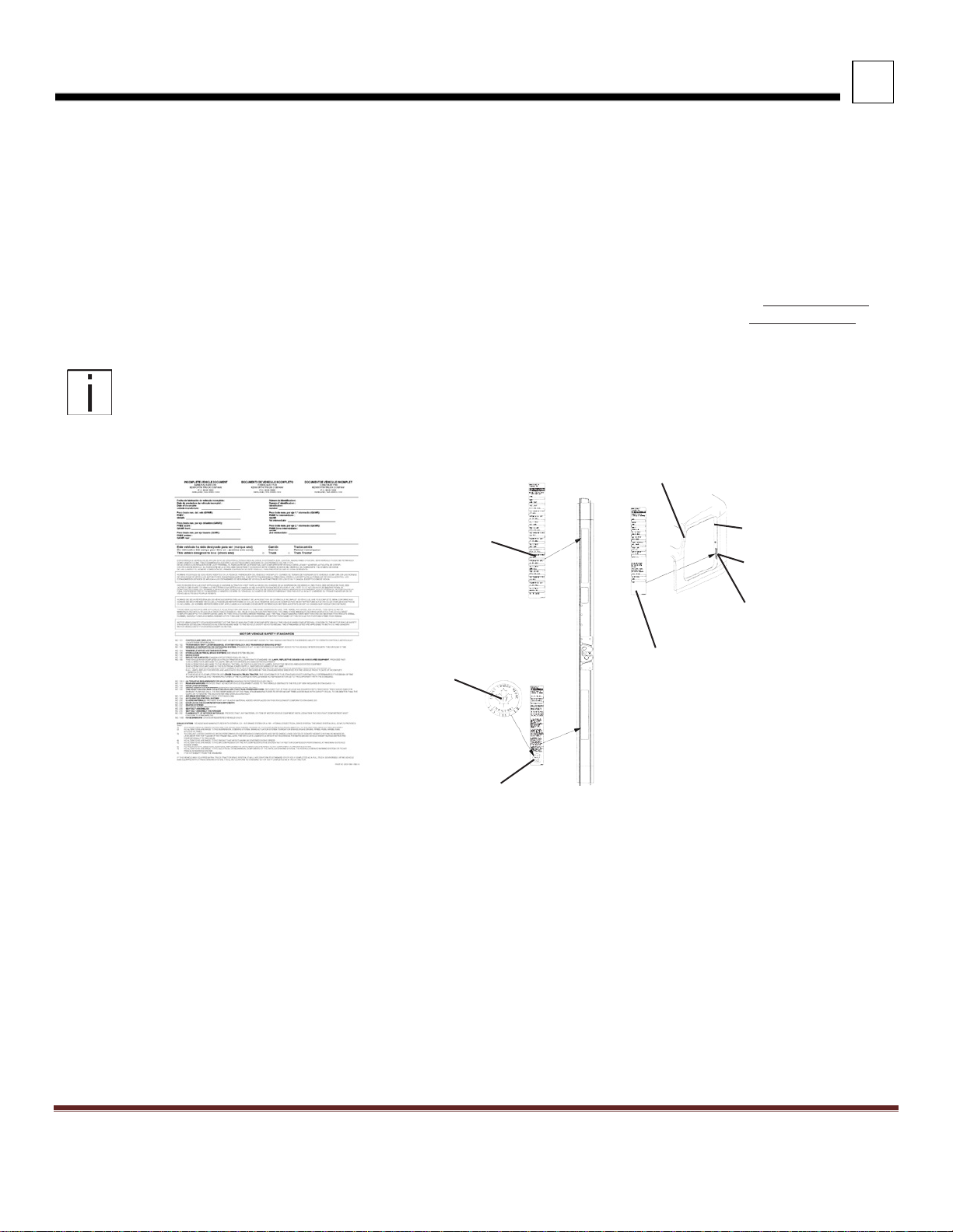
An Incomplete Vehicle Document is shipped with the vehicle, certifying that the vehicle is not complete. See Figure 2–1.
In addition, affixed to the driver’s side door frame or edge is an Incomplete Vehicle Certificati on la bel. See Figure 2–2.
NOTE
These documents list the U.S. or Canadian Federal Motor Vehicle Safety Standard regulations that the
vehicle complied with when it left the build plant. You should be aware that if you add, modify or alter any
of the components or systems covered by these regulations, it is your responsibility as the Intermediate or
Final Stage Manufacturer to ensure that the complete vehicle is in complianc e wit h the particu lar
regulations upon completion of the modifications.
FIGURE 2-1. Incomplete Vehicle Certification Document
Tire, Rim and
Weight Rating
Data label
Safety Mark (Canadian
Registry Only)
Incomplete Vehicle
Certification Label
FIGURE 2-2. Locations of Certifica- tion
Labels - Driver’s Door and Frame
U.S. EPA Noise Label (U.S. registered vehicles only)
Final Stage Manufacturer
Label to be installed by
Final Stage Manufacturer
Chassis Serial
Number
Vehicle Emission Control
Information Label
Major Components and
Weights Label
As the Intermediate or Final Stage Manufacturer, you should retain the Incomplete Vehicle Document for your records. In
addition, you should record and retain the manufacturer and serial number of the tires on the vehicle. Upon completion of
the vehicle (installation of the body and any other modifications), you should affix your certification label to the vehicle as
required by Federal law. This tag identifies you as the “Intermediate or Final Sta ge Manufacturer” and certifies that the
vehicle complies with Federal Motor Vehicle Safety Standards. (See Figure 2–2.) Be advised that regulations affecting the
intermediate and final stage manufacturer may change without notice. Ensure you are referencing the most updated copy
of the regulation during the certification and documentation processes.
In part, if the final stage manufacturer can complete and certify the vehicle within the instruction in the incomplete vehicle
document (IVD) the certification label would need a statement that reads, “This vehicle has been completed in accordance
with the prior manufacturers‚ IVD where applicable. This vehicle conforms to all applicable Federal Motor Vehicle Safety
Standards [and Bumper and Theft Prevention Standards if applicable] in effect in (month, year).”
Peterbilt Motors Company 2-2
Page 9

2
SAFETY AND COMPLIANCE
However, if the vehicle cannot be completed and certified with in the guidance provided in the IVD, the final stage
manufacturer must ensure the vehicle conforms to all applicable Federal Motor Vehicle Safety Standards (FMVSS). The
final stage manufactures certification label would need a statement that reads, “This vehicle conforms to all applicable
Federal Motor Vehicle Safety Standards [and Bumper and Theft Prevention Standards if applicable] in effect in (month,
year).
These statements are just part of the changes to the new certification regulation. Please refer to the Feb 15, 2005 final
rule for all of the details related to this regulation. You can contact NTEA Technical Services Department at 1-800-441NTEA for a copy of the final rule (DocID 101760).
For Canadian final stage manufacturers see:
http://www.gazette.gc.ca/index-eng.html;
and http://www.tc.gc.ca/eng/acts-regulations/menu.htm for the
regulations.
Or contact: Transport Canada
Tower C, Place de Ville, 330 Sparks Street
Ottawa, Ontario K1A 0N5 (613) 990-2309
TTY: 1-888-675-6863
NOISE AND EMISSIONS REQUIREMENTS
NOTE
This truck may be equipped with specific emissions control components/systems in order to
meet applicable Federal and California noise and exhaust emissions requirements. Tampering
with these emissions control components/systems is against the rules that are established by the
U.S Code of Federal Regulations, Environment Canada Regul ati ons a nd California Air Resources
Board (CARB). These emissions control c omponents/ systems may only be replaced with origin al
equipment parts.
Additionally, most vehicles in North America will be equipped with a Greenhouse Gas (GHG)
“Vehicle Emission Control Information” door label indicating its certified configuration. The vehicle
components listed on this label are considered emission control devices.
Modifying (i.e. altering, substituting, relocating) any of the emissions control components/systems
defined above will affect the noise and emissions performance/certification. Modifications that
alter the overall s ha pe and aer odynamic performance of a tractor will also affect the emission
certification. If modifications are required, they must first be approved by the manufacturer.
Unapproved modifications could negatively affect emissions performance/certification. There is no
guarantee that proposed modifications will be approved.
Tires may be substituted provided the new tires possess a Coefficient of rolling resistance (Crr)
equal to or lower than Crr of the original tires. Consult with your tire supplier(s) for appropriate
• For Cummins Contact 1-800-DIESELS or your local Cummins distributor. Reference AEB 21.102.
It is possible to relocate the DEF tank; however the relocation requirements need to be followed. Any variances from the
relocation requirements may cause the emissions control components/systems to operate improperly potentially resulting
in engine de-rate.
Peterbilt Motors Company 2-3
replacement tires.
Contact the engine manufacturer for any requirements and restrictions prior to any modifications.
Page 10

2
SAFETY AND COMPLIANCE
NOTE
To ensure compliance to emissions regulations, the final configuration of certain features of the completed vehicle must
meet specific requirements. This section describes requirements relevant for only the most common or critical
modifications done by body builders. For a complete description of acceptable modifications, see the application guidance
available from the manufacturer of the engine installed in the chassis.
All 2017 engine emissions certified vehicles will be equipped with an On-Board
Diagnostics (OBD) system. The OBD system is desig ned to d etect m alfunctions of any
engine or vehicle component that may increase exhaust em issions or interfere with the
proper performance of the OBD system itself
All diesel engines will be equipped with an On-Board Diagnostics (OBD) system. The
OBD sys tem consists of computer program on o ne or more of t he vehicle’s Electronic
Control Units (ECUs). This program uses information from the control system and from
additional sensors to detect malfunctions. When a malfunction is detected, information is
stored in the ECU(s) for diagnostic purposes. A Malfunction Indicator Light (MIL) is
illuminated in the dash to alert the driver of the need for service of an emission-related
component or system.
FUEL SYSTEM
The following are highlights of some of the more common or critical aspects of this system.
The overall system restriction may not exceed the restriction limitations set forth by the engine manufacturer for both
supply and return.
• Ensure that fuel lines are not pinched or can potentially be damaged when installed between body
and frame
• Fuel lines must be routed and secured without dips or sags
• There must be easy access to filter(s) and fill cap
• The tank vent may not obstructed
• Added accessories (heaters, generators) cannot introduce air into system
• Fuel tank must be located so that the full level is not above cylinder head
• “Ultra-Low Sulfur Fuel Only” labels must be present on the dash and fuel fill
• Modification of the pressure side secondary filter and plumbing is not allowed without engine
manufacturer approval
• Body installation of fuel tank or routing of lines must not cause significant increase in fuel temperature
• Fuel hoses shall meet or exceed OEM supplied hose material construction specifications
COMPRESSED AIR SYSTEM
The following are highlights of some of the more common or critical aspects of this system.
• Air system modification must meet applicable FMVSS regulations
• Compressed Air tank may not be modified
• Added devices or bodywork may not interfere with or rub air lines
Peterbilt Motors Company 2-3
Page 11

2
SAFETY AND COMPLIANCE
• Air supply to the engine doser may not be restricted or disconnected
• Air lines should be routed, protected from heat, and properly secured to prevent damage
from other components
• Care should be taken so that air lines do not rub against other components
• Care should be taken to protect the air system from heat sources
EXHAUST AND EXHAUST AFTER-TREATMENT SYSTEM
The following are highlights of some of the more common or critical aspects of this system.
• The following after-treatment and exhaust system components may not be modified:
• DPF assembly
• SCR Catalyst assembly
• Exhaust pipes between the engine and after-treatment devices (DPF, SCR Catalyst) and between
after-treatment devices
• NO
• PM Sensor
• The following modifications may only be done within the guidelines of the “DEF System Relocation Guide.”
• All DEF and coolant lines should be routed, protected, and properly secured to prevent damage during
• If relocation of the DCU or ACM is necessary, use existing frame brackets and mount inside of frame
• The DPF, the SCR catalyst, or their mounting may not be modified
• The NOx sensor may not be relocated or altered in any way; this includes re-clocking the
• Exhaust pipes used for tailpipes/stacks must be properly sized, and must prevent water from entering
• Ensure ade quate clearance between the exhaust and body panels, hoses, and wire harnesses
• The body in the vicinity of the DPF must be able to withstand temperatures up to 400°C (750°F)
• Do not add thermal insulation to the external surface of the DPF
• The SCR water drain hole may not be blocked
Sensors
x
• Modifications to Diesel Exhaust Fluid (DEF) throttle, suction, or pressure lines
• Modification or relocation of the DEF tank
• Modification of coolant lines to and from the DEF tank
vehicle operation or other components
flanges where necessary. Do not extend the harnesses
aftertreatement canister or reorienting the sensor(s)
• Allow adequate clearance (25mm (1 inch)) for servicing the DPF sensors, wiring, and clamped joints
• Drainage may not come in contact with the DPF, SCR catalyst, sensors or wiring
Peterbilt Motors Company 2-5
Page 12

2
SAFETY AND COMPLIANCE
• Allow sufficient clearance for removing sensors from DPF. Thermistors require four inches. Other
sensors require one inch
• Wiring should be routed, protected from heat, and properly secured to prevent damage
from other components
• The exhaust system from an auxiliary power unit (APU) must not be connected to any part of the
vehicle after-treatment system or vehicle tail pipe.
COOLING SYSTEM
The following are highlights of some of the more common or critical aspects of this system.
• Modifications to the design or locations of fill or vent lines, heater or defroster core, and surge tank are
not recommended
• Additional accessories plumbed into the engine cooling system are not permitted, at the risk of voiding
vehicle warranty
• Coolant level sensor tampering will void warranty
• When installing auxiliary equipment in front of the vehicle, or additional heat exchangers, ensure
that adequate air flow is available to the vehicle cooling system. Refer to engine manufacturer
application guide- lines for further detail
• When installing FEPTO drivelines, the lower radiator anti-recirculation seal must be retained with
FEPTO driveline clearance modification only
• Changes made to cooling fan circuit and controls are not allowed, with the exception of AC
minimum fan on time parameter
• See owner’s manual for appropriate winter front usage
AIR INTAKE SYSTEM
The following are highlights of some of the more common or critical aspects of this system.
• The air intake screen may not be blocked, either fully or partially
• Modification to the air intake system may not restrict airflow. For example, pipe diameter may not be reduced
• All sensors must be retained in existing locations
• To retain system seal, proper clamp torque must be used. Refer to service manual for proper clamp torque
CHARGE AIR COOLER SYSTEM
The following are highlights of some of the more common or critical aspects of this system.
• The Charge Air Cooler may not be modified
• The installation of engine overspeed shutdown devices must not introduce restriction in the intake system
• All plumbing associated with the charge air cooler may not be modified
Peterbilt Motors Company 2-6
Page 13

2
SAFETY AND COMPLIANCE
ELECTRICAL SYSTEM
The following are highlights of some of the more common or critical aspects of this system.
• Electr ic al harnes ses providing battery power and electronic control signals to engine and emissions
control/ vehicle OBD components including datalinks may not be spliced. These emissions
control/vehicle OBD components include the following:
• throttle pedal
• vehicle speed sensor
• after-treatment wiring
• 9-pin OBD Connector
• CAN Communication / OBD Diagnostic wiring
• If the alternator or battery is substituted, it must meet the requirements of the engine manufacture’s
guidelines. This includes alternator ground voltage drop and alternator ground cable effectiveness.
See the engine manufacture’s guidelines for recommended test procedure. Additionally the
maximum voltage differential and the peak-peak voltage differential between the engine ECM block
ground stud and battery negative terminal may not exceed 500 mV under any combination of loads
or operating conditions.
• Only an OBD compliant battery disconnect switch may be installed on vehicles equipped EPA 2013
and beyond compliant diesel engines. An OBD compliant switch and harness, even in the off position,
supply a small amount of power to the engine controller and enable certain emissions critical
functions (e.g. DEF line purge). Any modifications to the electrical system which interrupt this power
supply will cause OBD fault codes and illumination of the MIL. In addition, such a modification will
render the engine non-compliant with certain emission regulations. As a general rule of thumb, you
can remove and replace a battery disconnect switch on a truck equipped with a battery disconnect
switch at the factory. However, if a battery disconnect switch was not installed in the factory a
significant harness modification is required before a battery disconnect switch can be added.
• Installation of aftermarket transfer-cases must address the vehicle speed sensor position. The
standard position of the speed sensor is at the transmission tail shaft. When a transfer-case is added
it is best to relocate the sensor to the axle side output shaft of the transfer-case. This is typically
accomplished by adding a tone wheel into the driveline yoke assembly.
• Wiring extensions for the after-treatment wiring are available for relocating the DEF tank from your
dealer via Paccar Parts. For relocation of DEF tank, refer to the after-treatment section of this
manual.
• The OBD/Diagnostic connector port is located below the dash to the left of the steering wheel. This
connector and its location may not be changed.
Peterbilt Motors Company 2-7
Page 14

This page is intentionally left blank.
Page 15

SECTION 3 DIMENSIONS
CA
Cab to axle. Measured from the back of the cab to the centerline of the rear axle(s).
RS
Rear suspension height
BOC
Back of cab
BFA
Bumper to front axle
Front engine PTO extension. Measured from the front of the grille to the front of the
bumper
INTRODUCTION
This section has been designed to provide enough information to successfully layout a chassis in the body planning
process. All dim ensions are inches un less o therwise noted. Opt ion al eq ui pment may not be depic ted . Ple as e contact your
local Peterbilt dealer if more dimension al inf ormation is desired.
ABBREVIATIONS
Throughout this sectio n and in other sections as wel l, abbreviations are used t o describe certain character istics on your
vehicle. The chart below lists the abbreviated terms used.
TABLE 3-1. Abbreviations Used
FS Front suspension height
SOC Side of cab
BBC Bumper to back of cab
FAB Front axle to back of cab
FEPTO
OVERALL DIMENSIONS
This section includes dr awings and charts of the following Peterbilt Models: 348 (110” BBC), 348 ( 108” BBC), 337 (110”
BBC), 337 (108” BBC), 330, and 325. Several optional configurations are also included.
On the pages that follow, deta il drawings show particular views of each vehic le; all dimensions are in inches (in). T hey
illustrate important m easurem ents critical to des igning bodies of all types. See the “ Table of Contents ” at the beginning of
the manual to locate the drawing that you need.
All heights are given from the bottom of the frame rail.
Peterbilt also offers .dxf files and frame la youts of ord ered chass is prior to bu ild. Please sp eak with your local dealer ship
to request this feature when specifying your chassis.
Page 16
3
DIMENSIONS
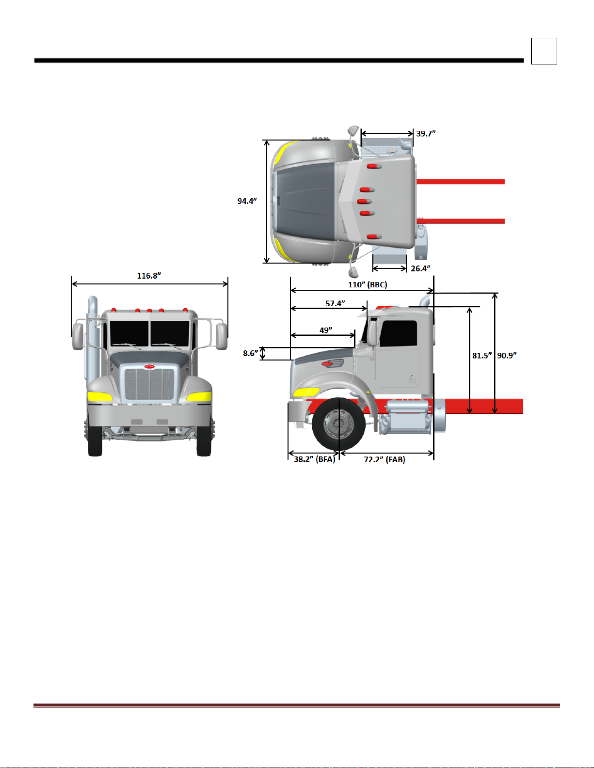
MODEL 348, 337 (110” BBC)
NOTES:
1) DIMENSIONS ARE FOR REFERENCE ONLY
2) DIMENSIONS ARE TO FRONT OF 0.125” THICK BUMPER
3) DIMENSION FRONT AXLE TO FRONT OF FRAME (FFA) IS 36.2”
4) DIMENSION FRONT OF BUMPER TO FRONT OF FRAME (BFF) IS 2.1”
5) DIMEN SIO N S AR E WITH 11 5/8” RAIL
FIGURE 3-1. Model 348, 337 (110” BBC) Top, Front, & LH View – Overall Dimensions
Peterbilt Motors Company 3- 2
Page 17

3
DIMENSIONS
MODEL 348, 337, 330, 325 (108” BBC)
FIGURE 3-2. Model 348, 337, 330, 325 (108” BBC) Top, Front & LH View – Overall Dimensions
NOTES:
1) DIMENSIONS ARE FOR REFERENCE ONLY
2) DIMENSIONS ARE TO FRONT OF 0.125” THICK BUMPER
3) DIMENSION FRONT AXLE TO FRONT OF FRAME (FFA) IS 34.9”
4) DIMENSION FRONT OF BUMPER TO FRONT OF FRAME (BFF) IS 1.3”
5) DIMESNIONS ARE WITH 10 5/8” RAIL
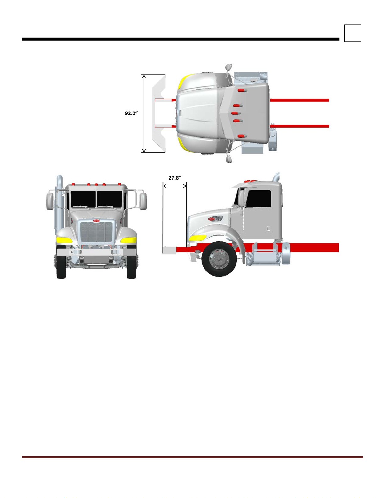
MODEL 348, 337 (110” BBC) and 348, 337 (108” BBC) w/ 27.8” FEPTO Bump er E xtension
Peterbilt Motors Company 3- 3
Page 18
3
DIMENSIONS
NOTES:
1) DIMENSIONS ARE FOR REFERENCE ONLY
2) DIMENSIONS ARE TO FRONT OF 0.25” THICK BUMPER
3) DIMENSION FRONT OF BUMPER TO FRONT OF FRAME (BFF) IS 0.92”
FIGURE 3-3. 348, 337 (110” BBC) and 348, 337 (108” BBC) Top, Front & LH View – Overall Dimensions
Peterbilt Motors Company 3- 4
Page 19
3
DIMENSIONS
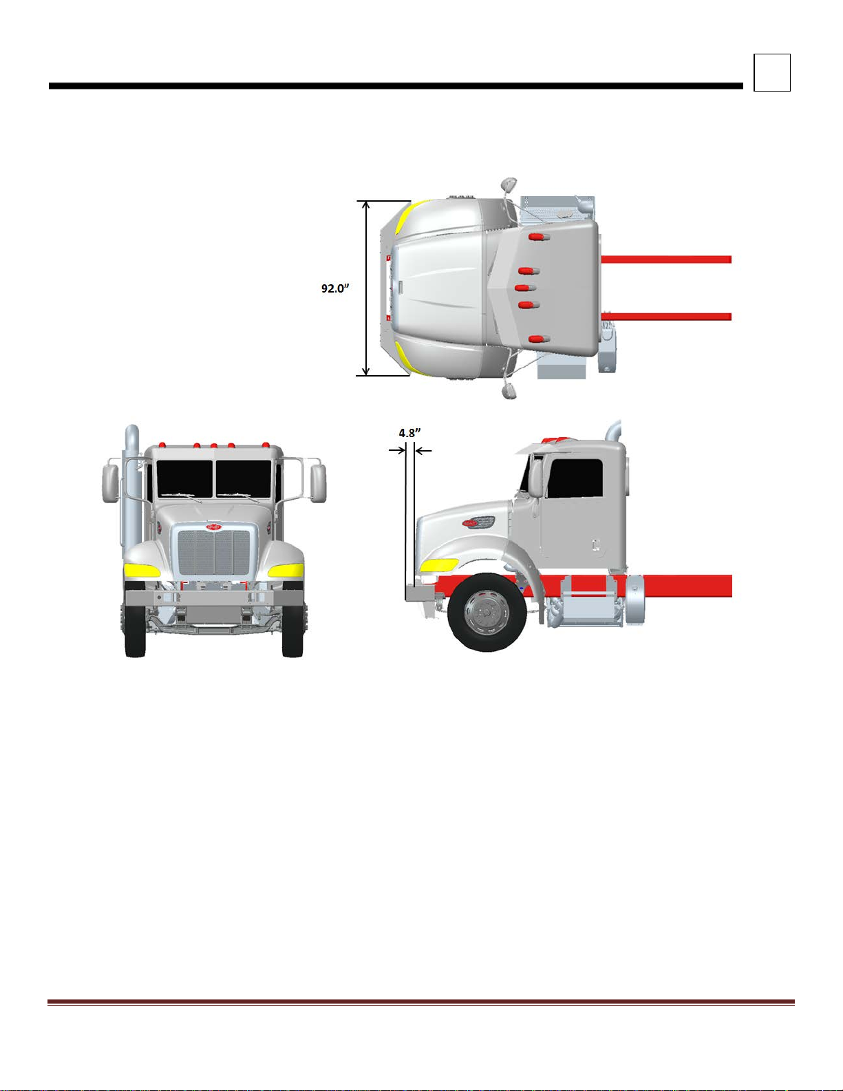
MODEL 348, 337 (110” BBC) and 348, 337 (108” BBC) w/ 3.2” FEPTO Bumper Extension
NOTES:
1) DIMENSIONS ARE FOR REFERENCE ONLY
2) DIMENSIONS ARE TO FRONT OF 0.25” THICK BUMPER
3) DIMENSION FRONT OF BUMPER TO FRONT OF FRAME (BFF) IS 2.92”
FIGURE 3-4. Model 348, 337 (110” BBC) and 348, 337 (108” BBC) 337 Top, Front & LH View – Overall Dimensions
Peterbilt Motors Company 3- 5
Page 20
3
DIMENSIONS
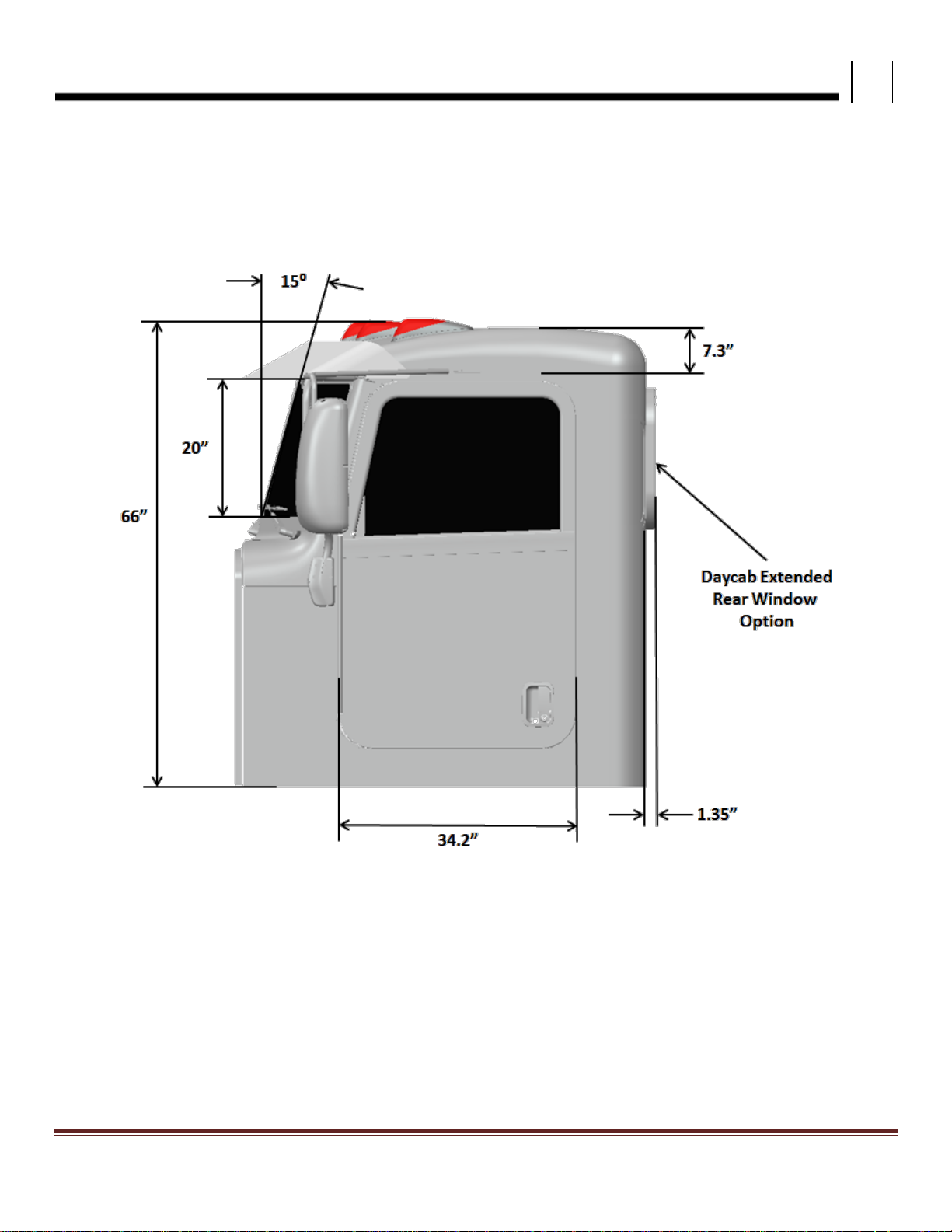
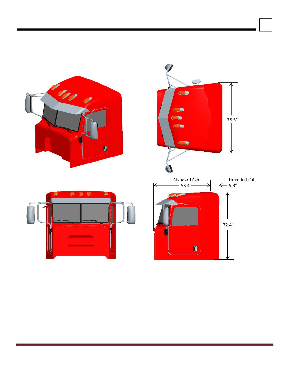
CAB – 1.9m MEDIUM DUTY CAB FAMILY
Models 348, 337 (110” BBC), 348 (108” BBC), 337, 330, 325
FIGURE 3-5. Cab Dimensions 1.9m Medium Duty Cab Family
Peterbilt Motors Company 3- 6
Page 21
3
DIMENSIONS
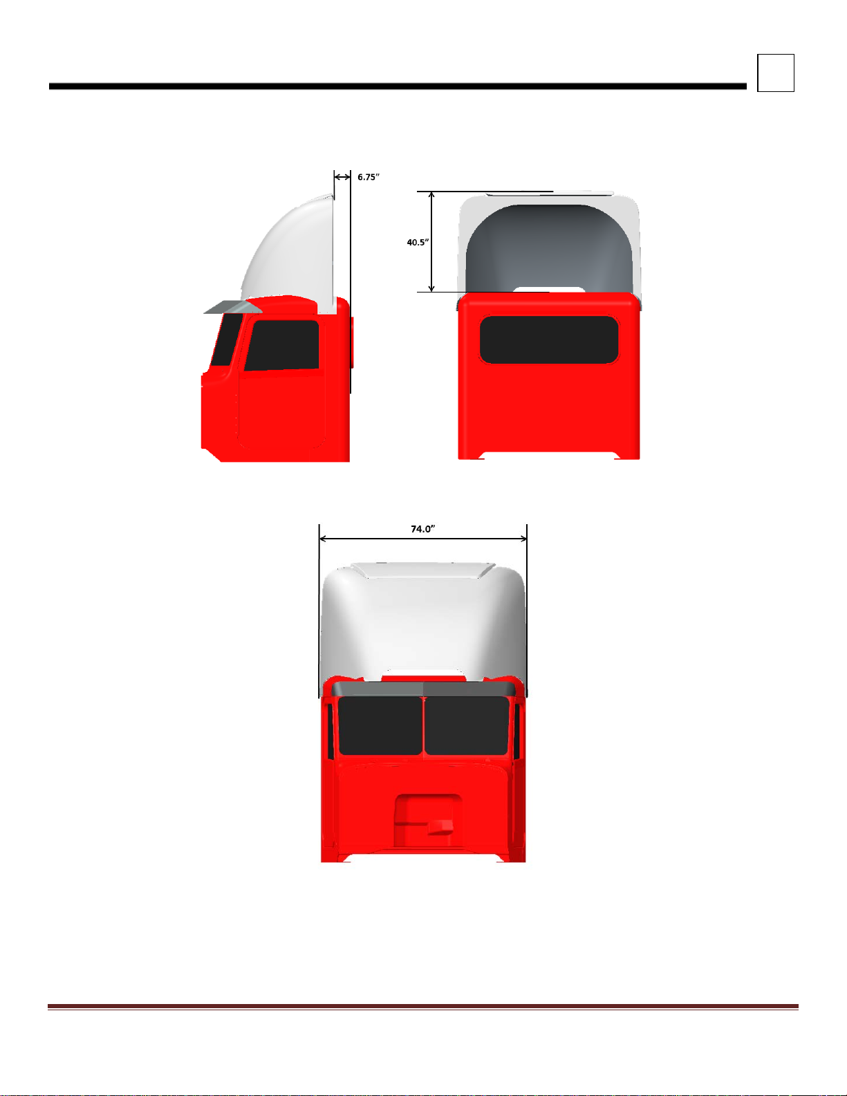
ROOF FAIRING
FIGURE 3-6. Roof Fairing Dimensions
Peterbilt Motors Company 3- 7
Page 22
3
DIMENSIONS
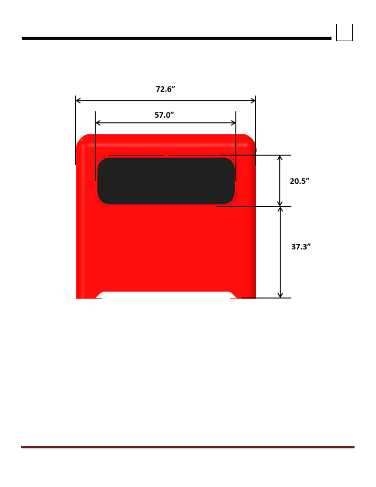
REAR WINDOW
FIGURE 3-7. Rear Window Dimensions
Peterbilt Motors Company 3- 8
Page 23
3
DIMENSIONS
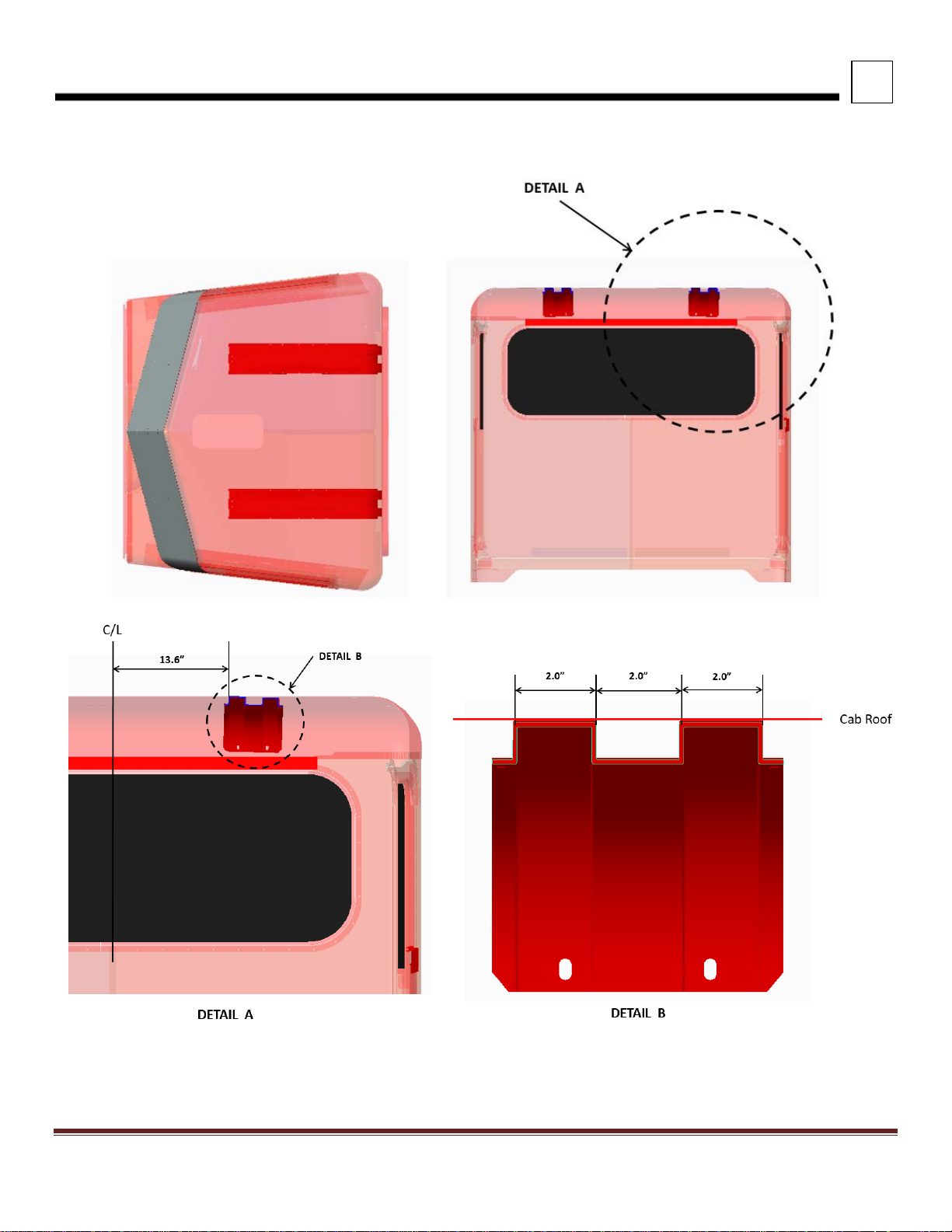
ROOF BOW STRUCTURE
FIGURE 3-8. Roof Bow Structure
Peterbilt Motors Company 3- 9
Page 24
3
DIMENSIONS
CABMATE CAB SUSPENSION
FIGURE 3-9. Cabmate Cab Suspension Dimensions
Peterbilt Motors Company 3- 10
Page 25

3
Description (2)
A (First Step)
B (Second Step)
C (Cab Floor) (1)
Aluminum Battery Box
13.4”
2.75”
18.2”
Steel Battery Box
10.7”
3.3”
18.2”
Model 325 Battery Box
1” - 18.2”
23” Fuel Tank
11.3”
6.7”
18.2”
26” Fuel Tank
11.5”
4.4”
18.2”
Rectangular Fuel Tank
8.6”
9.7”
18.2”
RH UCAB Aftertreatment Box (3)
10.5”
6”
18.2”
DIMENSIONS
CAB STEP HEIGHT
FIGURE 3-10. Cab Step Height Dimensions (Table 3-2)
Table 3-2. Cab Step Height
Notes
1.) Add 2.75” to the C Dimension for BBC 110” Hood or Raised Cab Option
2.) LH shown, RH Dimensions are equivalent
3.) Aftertreatment box is RH UCAB only
Peterbilt Motors Company 3- 11
Page 26
3
DIMENSIONS
EXTENDED CAB – 1.9m MEDIUM DUTY CAB FAMILY
Models 348, 337 (110” BBC), 348 (108” BBC), 337, 330
FIGURE 3-11. Extended Cab
Peterbilt Motors Company 3- 12
Page 27
3
DIMENSIONS
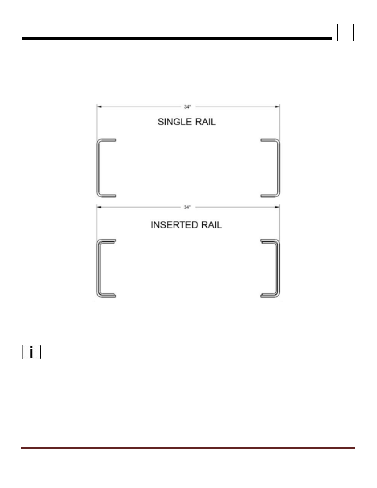
FRAME RAILS
Frame rail configurations are shown below. Frame height, flange and structural values can be found in the Body
Mounting Section.
FIGURE 3-12. Frame Rail Configurations
NOTE: The outserted frame section does not extend through the rear suspension area.
Peterbilt Motors Company 3- 13
Page 28
3
DIMENSIONS
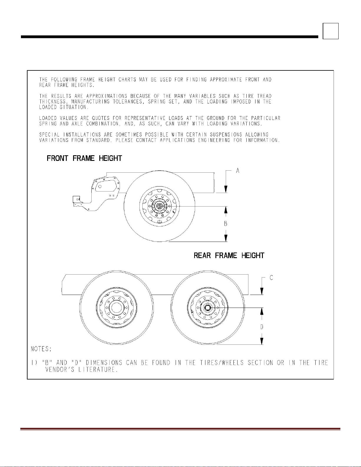
FRAME HEIGHT CHARTS
FIGURE 3-13. Frame Height
Peterbilt Motors Company 3- 14
Page 29
3
DIMENSIONS
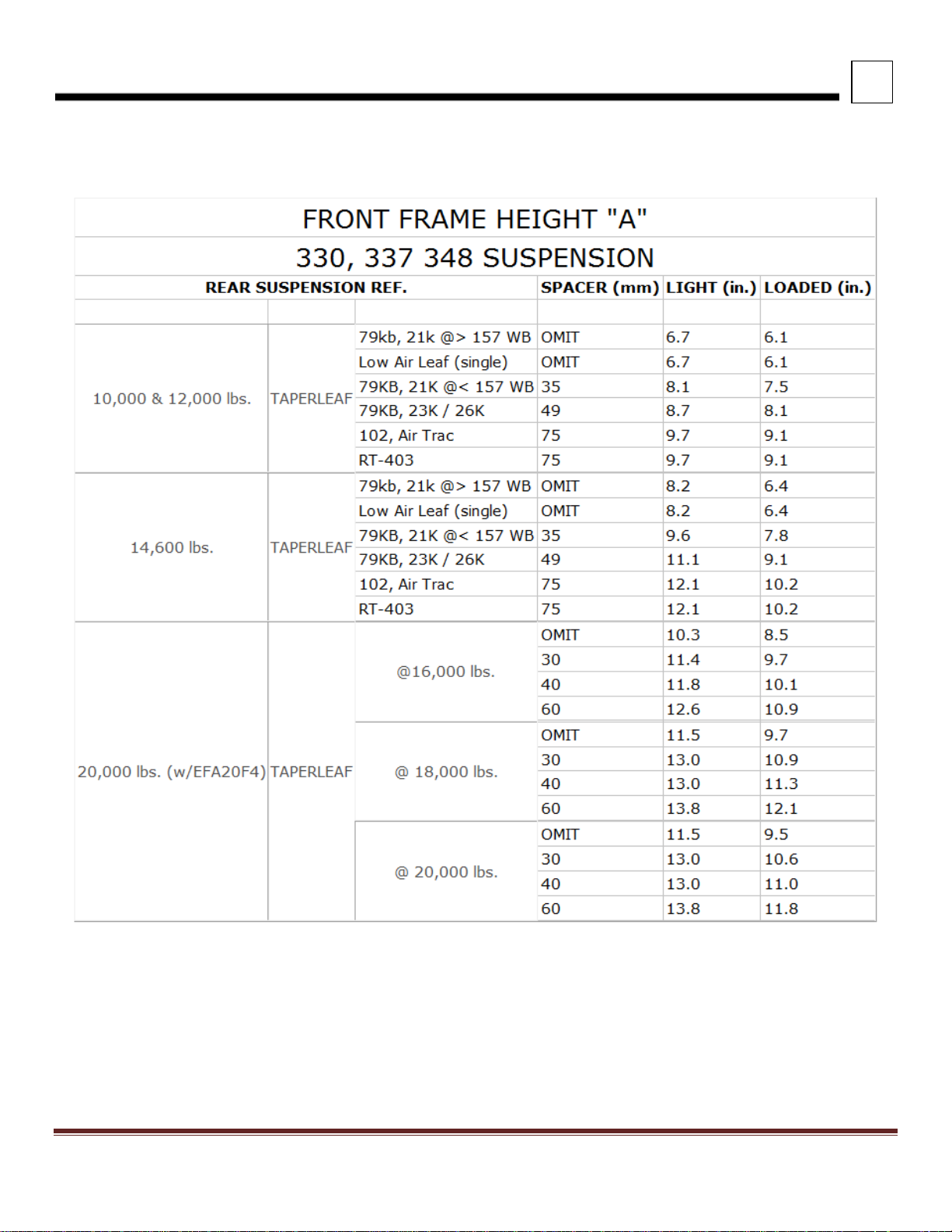
FRONT FRAME HEIGHTS "A"
TABLE 3-3. Front Frame Height “A”
NOTES:
1) Spacers are used by Engineering to obtain a level frame and are not options.
2) LIGHT or UNLADEN heights are calculated on the below assumptions
a. 12K or 14.6K springs assumes 8,000 lbs. load in LIGHT condition
b. 16K springs assumes 8,500 lbs. load in LIGHT condition
c. 18K - 20K springs assumes 9,000 lbs. load in LIGHT condition
3) "A" dimension shown is to bottom of frame rail. Add frame rail height dimension for frame height.
Peterbilt Motors Company 3- 15
Page 30

3
Suspension
Rating
Version
Light
Height
Laden
Height
20,000 lbs.
Standard
11.4
11.0
23,000 lbs.
Standard
11.4
11.0
20,000 lbs.
Taperleaf (3.38" saddle)
9.4
11.8
21,000 lbs.
Taperleaf (1.38" saddle)
7.4
9.8
23,000 lbs.
Multileaf (1.38" saddle)
8.8
11.6
26,000 lbs.
Multileaf (1.38" saddle)
9.2
11.8
28,000 lbs.
Multileaf (1.38" saddle)
9.7
12.3
31,000 lbs.
Multileaf (1.38" saddle)
10.8
13.3
23K-29K lbs.
4.38 saddle
12.1
10.2
23K-29K lbs.
4.63 saddle
12.2
10.4
29,000 lbs.
3.50 saddle
11.7
10.0
31,000 lbs.
3.50 saddle
12.2
10.5
31,000 lbs.
4.38 saddle
12.5
10.7
31,000 lbs.
4.63 saddle
12.7
10.9
Standard
9.3
9.3
Low
8.3
8.3
Suspension
Rating
Version
Light
Height
Laden
Height
AIR LEAF
38,000 lbs.
12.0
11.7
LOW AIR LEAF
40,000 lbs.
8.8
8.5
FLEX AIR
38,000 lbs.
8.7
8.5
LOW LOW AIR LEAF
40,000 lbs.
6.8
6.5
AIR TRAC
40K-46K lbs.
11.4
11.0
Suspension
Rating
Version
Light
Height
Laden
Height
NEWAY ADZ
46K lbs.
10.0
10.0
DIMENSIONS
REAR FRAME HEIGHTS "C"
TABLE 3-4. Single Drive Rear Suspension Height “C”
AIR TRAC
REYCO 79KB
REYCO 102
REYCO 102AR (AIR) 17K -23K
TABLE 3-5. Tandem Peterbilt Rear Suspension Height “C”
TABLE 3-6. Tandem Neway Rear Suspension Height “C”
Peterbilt Motors Company 3- 16
Page 31

3
Suspension
Rating
Version
Light
Height
Laden
Height
1.75 saddle (STD)
11.7
9.9
1.38 saddle
10.2
8.3
3.38 saddle
13.4
11.5
1.75 saddle (STD)
11.7
9.8
1.38 saddle
11.5
9.7
Suspension
Rating
Version
Light
Height
Laden
Height1
LOW
11.2
8.9
HIGH
12.4
10.2
X-HIGH
14.5
12.2
XXHIGH
17.2
14.9
LOW
11.3
8.9
HIGH
12.5
10.1
X-HIGH
14.7
12.2
XXHIGH
17.3
14.9
Suspension
Rating
Version
Light
Height
Laden
Height
6.00 saddle
9.9
8.9
7.19 saddle (std.)
11.2
10.1
16.5 saddle (low)
10.6
9.5
18.5 saddle (std.)
12.6
11.5
16.5 saddle (low)
10.6
9.5
18.5 saddle (std.)
12.6
11.5
12.25 saddle
9.7
8.9
14.00 saddle
(std.)
11.5
10.6
15.25 saddle
12.7
11.9
6.00 saddle
11.3
10.5
7.2 saddle (std.)
13
11.4
11.00 saddle
16.3
15.2
DIMENSIONS
REYCO 102 MULTILEAF
TABLE 3-7. Tandem Reyco Rear Suspension Height “C”
40,000 lbs.
44,000 lbs.
TABLE 3-8. Tandem Chalmers Rear Suspension Height “C”
CHALMERS 854 40,000 lbs.
CHALMERS 854 46,000 lbs.
TABLE 3-9. Tandem Hendrickson Suspension Height “C”
RT-403 40,000 lbs.
HMX 40,000 lbs.
HMX 46,000 lbs.
RS-463 46,000 lbs.
RT-463 46,000 lbs.
Peterbilt Motors Company 3- 17
Page 32

3
DIMENSIONS
FRAME SPACE REQUIREMENTS
To ensure adequate space for fuel tanks, ladder steps, additional tool/battery boxes, pusher axles and other frame
mounted components; the amount of available space must be calculated by using the formula below. Contact Applications
Engineering for configurations not shown in this section. Examples are shown at the end of this section.
FIGURE 3-14. Frame Space
BASIC FORMULA: BOC Frame Space = Wheelba s e - Dimension A - Dimension C - Dimension B
Dimension "A" (shown in charts on following pages) is the minimum clearance measured from the centerline of the front
axle to the back of the under cab component (DPF/SCR exhaust, fuel tank, battery box, tool box, etc). Dimension "C" is
the amount of space from the rear of the under cab component to the back of the DEF tank (can be on LH or RH
rail). Dimension "B" is the amount of required suspension and quarter fender clearance from the rear axle centerline to
clear rail for a given suspension.
Peterbilt Motors Company 3- 18
Page 33

3
REAR SUSPENSION
"B"
OVERHANG (1)
NOTES
AIR LEAF
53.0
53.0
2
LOW/ LOW LOW AIR LEAF
62.4
53.0
LOW AIR LEAF SINGLE
36.5
27.0
AIR TRAC SINGLE
27.0
27.0
3
AIR TRAC TANDEM
53.0
53.0
3
FLEX AIR
59.0
53.7
7
CHALMERS 800 (54" SPACING)
49.0
52.0
4
HENDRICKSON HLM / AL
26.6
N/A
6
HENDRICKSON HLR2
30.5
N/A
6
HENDRICKSON HMX, HN
53.0
54.0
HENDRICKSON R/RS/RT/RTE
53.0
53.0
3
HENDRICKSON SC20
25.6
15.0
6
HENDRICKSON SC8/10/13, FX, FXO, SCO
23.6
13.8
5, 6
NEWAY ADZ (54" SPACING)
61.0
58.3
REYCO 102 SINGLE
30.0
25.8
REYCO 102AR SINGLE
30.0
31.0
REYCO 102 TANDEM
56.0
52.7
REYCO 79KB
30.1
32.2
WATSON-CHALIN AL2200
26.6
22.2
6
WATSON-CHALIN SL0893SSR
27.6
11.8
5, 6
WATSON-CHALIN SL1093SSR
27.6
11.8
6
WATSON-CHALIN SL1190SSR
26.0
12.8
6
WATSON-CHALIN SL2065
27.6
14.4
6
DIMENSIONS
FRAME SPACE DIMENSION "B"
TABLE 3-10. Rear Suspension Dimension “B”
DIMENSION "B" IN INCHES (52" Axle Spacing on Tandems)
FRAME SPACE REQUIREMENTS
NOTES:
1) Overhang for Tractor Taper EOF and Standard Mud flap Hangers on Suspensions; Square EOF w/o
Crossmember for Lift Axles.
2) Add 2.0" to "C" dimension with quarter fenders .
3) Add 1.5" to "C" dimension with quarter fenders .
4) Add 0.6" to "C" dimension with quarter fenders.
5) Add 2.8" to "C" dimension with quarter fenders .
6) "C" dimension is from axle centerline (or bogie for tandem) to clear frame forward.
7) Extended Tractor Taper requires 58.0" overhang.
Peterbilt Motors Company 3- 19
Page 34

3
DIMENSIONS
FRAME SPACE DIMENSION “A” AND “C”
Peterbilt Motors Company 3- 20
Page 35

3
DIMENSIONS
CONTINUED FRAME SPACE DIMENSION “A” AND “C” FOR MODEL 325, 330, 337, 348-108”
Peterbilt Motors Company 3- 21
Page 36

3
DIMENSIONS
Peterbilt Motors Company 3- 22
Page 37

3
DIMENSIONS
2017 MD EXHAUST CONFIGURATIONS
EXHAUST SINGLE RH SIDE OF CAB DPF/SCR RH UNDER CAB
(Reference option code 3365270)
FIGURE 3-16. Exhaust Single RH Side of Cab DPF/SCR RH Under Cab
Peterbilt Motors Company 3- 23
Page 38

3
DIMENSIONS
EXHAUST SINGLE RH BACK OF CAB DPF/SCR RH UNDER CAB
(Reference option code 3365250)
FIGURE 3-17. Exhaust Single RH Back of Cab DPF/SCR RH Under Cab
Peterbilt Motors Company 3- 24
Page 39

3
DIMENSIONS
EXHAUST SINGLE RH HORIZONTAL DPF /SCR RH UNDER CAB
(Reference option code 3365280)
FIGURE 3-18. Exhaust Single RH Horizontal DPF/SCR RH Under Cab
Peterbilt Motors Company 3- 25
Page 40

3
DIMENSIONS
EXHAUST SINGLE RH HORIZONTAL DPF /SCR RH UNDER FRAME
(Reference option code 3365290)
FIGURE 3-19. Exhaust Single RH Horizontal DPF/SCR RH Under Frame
Peterbilt Motors Company 3- 26
Page 41

3
DIMENSIONS
PTO LAYOUTS
PTO LAYOUT MODEL 348-110” or 337-110”, PX-9, 4000 SERIES ALLISO N
Figure 3-20. Model 348-110” or 337-110”, PX -9 4000 Series Allison
Peterbilt Motors Company 3- 27
Page 42

3
DIMENSIONS
PTO LAYOUT MODEL 348-110” OR 337-110” WITH PX-9 AND 4000 SERIES ALLISON
Figure 3-21. Model 348-110” or 337-110”, PX -9 4000 Series Allison
Peterbilt Motors Company 3- 28
Page 43

3
DIMENSIONS
PTO LAYOUT MODEL 348-110” OR 337-110” WITH PX-9 AND 4000 SERIES ALLISON
Figure 3-22. Model 348-110” or 337-110”, PX -9 4000 Series Allison
Peterbilt Motors Company 3- 29
Page 44

3
DIMENSIONS
PTO LAYOUT MODEL 348-110” OR 337-110” WITH PX-9 AND 4000 SERIES ALLISON
Figure 3-23. Model 348-110” or 337-110”, PX -9 4000 Series Allison
Peterbilt Motors Company 3- 30
Page 45

3
DIMENSIONS
PTO LAYOUT MODEL 348-110” OR 337-110” WITH PX-9 AND 4000 SERIES ALLISON
Figure 3-24. Model 348-110” or 337-110”, PX-9 4000 Series Allison
Peterbilt Motors Company 3- 31
Page 46

3
DIMENSIONS
PTO LAYOUT MODEL 348-110” OR 337-110” WITH PX-9 AND 3000 SERIES ALLISON
Figure 3-25. Model 348-110” or 337-110”, PX -9 3000 Series Allison
Peterbilt Motors Company 3- 32
Page 47

3
DIMENSIONS
PTO LAYOUT MODEL 348-110” OR 337-110” WITH PX-9 AND 3000 SERIES ALLISON
Figure 3-26. Model 348-110” or 337-110”, PX-9 3000 Series Allison
Peterbilt Motors Company 3- 33
Page 48

3
DIMENSIONS
PTO LAYOUT MODEL 348-110” OR 337-110” WITH PX-9 AND 3000 SERIES ALLISON
Figure 3-27. Model 348-110” or 337-110”, PX -9 3000 Series Allison
Peterbilt Motors Company 3- 34
Page 49

3
DIMENSIONS
PTO LAYOUT MODEL 348-1 10” OR 337-110” WITH PX-9 AND 3000 SERIES ALLISON
Figure 3-28. Model 348-110” or 337-110”, PX -9 3000 Series Allison
Peterbilt Motors Company 3- 35
Page 50

3
DIMENSIONS
PTO LAYOUT MODEL 348-1 10” OR 337-110” WITH PX-9 AND 3000 SERIES ALLISON
Figure 3-29. Model 348-110” or 337-110”, PX -9 3000 Series Allison
Peterbilt Motors Company 3- 36
Page 51

3
DIMENSIONS
PTO LAYOUT MODEL 348-1 10” OR 337-110” WITH PX-9 AND 3000 SERIES ALLISON
Figure 3-30. Model 348-110” or 337-110”, PX -9 3000 Series Allison
Peterbilt Motors Company 3- 37
Page 52

3
DIMENSIONS
PTO LAYOUT MODEL 348-1 10” OR 337-110” WITH PX-9 AND 3000 SERIES ALLISON
Figure 3-31. Model 348-110” or 337-110”, PX -9 3000 Series Allison
Peterbilt Motors Company 3- 38
Page 53

3
DIMENSIONS
PTO LAYOUT MODEL 348-110” OR 337-110 ” WITH PX-9 AND 3000 SERIES ALLISON
Figure 3-32. Model 348-110” or 337-110”, PX -9 3000 Series Allison
Peterbilt Motors Company 3- 39
Page 54

3
DIMENSIONS
PTO LAYOUT MODEL 348-1 10” OR 337-110” WITH PX-9 AND 3000 SERIES ALLISON
Figure 3-33. Model 348-110” or 337-110”, PX-9 3000 Series Allison
Peterbilt Motors Company 3- 40
Page 55

SECTION 4 BODY MOUNTING
(in.)
(in.)
(in)
Section
(cu. In.)
(in.-lbs)
(lbs/in.)
9 7/8
3.50
0.250
10.5
1,250,000
1.06
10 1/4
3.50
0.250
11.7
1,400,000
1.15
10 5/8
3.45
0.313
14.8
1,776,000
1.44
10 3/4
3.50
0.375
17.8
2,136,000
1.74
Main Rail
(in.)
Insert
Outsert
Section
(cu. In.)
(in.-lbs)
(lbs/in.)
10 5/8
9.875 x 2.87 x .250
None
23.6
2,832,000
2.48
10 3/4
9.875 x 2.87 x .250
None
28.9
3,468,000
2.78
10 3/4
9.875 x 2.87 x .250
11.625 x 3.87 x .375
45.7
5,484,000
4.67
INTRODUCTION
This section has been desi gned to provide guid elines to aid in bod y mounting. This is not int ended as a complete guide,
rather as general information. Body mounting s trategies are unique to each b ody type and body builder m ust determine
the appropriate method.
Please contact your local Peterbilt dea ler if mor e information is desired.
FRAME RAILS
Frame rail information is provided per rail.
TABLE 4-1. Single Frame Rails
Rail Height
Height
Flange Width
Web Thickness
TABLE 4-2. Built-up Frame Rails
Modulus
Modulus
RBM (per rail)
RBM (per rail)
Weight (per rail)
Weight (per rail)
Page 56

4
BODY MOUNTING
CRITICAL CLEARANCES
REAR TIRES AND CAB
CAUTION: Insufficient clearance between rear tires and body structure could cause damage to the body during
suspension movement.
Normal suspension m ovement could cause contact b etween the tires and the body. To prevent this, m ount the body so
that the minimum clearance betwee n the top of the t ire and the bottom of the bod y is 8 inches (20 3 mm). This shou ld be
measured with the body empty. See FIGURE 4-1.
FIGURE 4-1. Minimum Clearance Between Top of Rear Tires and Body Structure Overhang
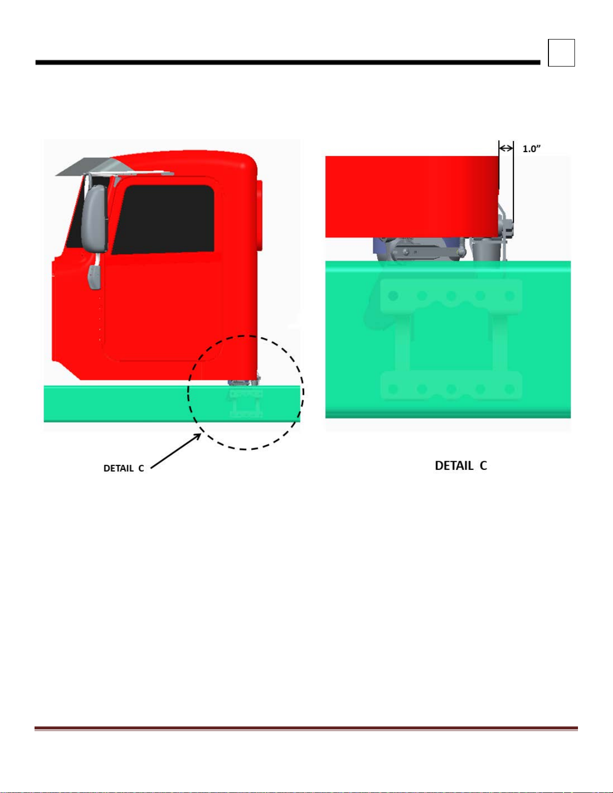
CAUTION: Maintain adequate clearance between back of cab and the front (leading edge) of mounted body. It is
recommended the body leading edge be mounted 4 in. behind the cab. See FIGURE 4-2.
NOTE: Be sure to provide maintenance access to the battery box and fuel tank fill neck.
FIGURE 4-2. Minimum Back of Cab Clearance
Peterbilt Motors Company 4-2
Page 57

4
BODY MOUNTING
BODY MOUNTING USING BRACKETS
CAUTION: Always install a spacer between the body subframe and the top flange of the frame rail. Installation of
a spacer between the body subframe and the top flange of the frame rail will help prevent premature wear of the
components due to chafing or corrosion.
WARNING! When mounting a body to the chassis, DO NOT drill holes in the upper or lower flange of the
frame rail. If the frame rail flanges are modified or damaged, the rail could fail prematurely and cause an
accident. Mount the body using body mounting brackets or U–bolts.
FRAME SILL
If the body is mounted to the frame with brackets, we recommend a frame sill spacer made from a strip of rubber or plastic
(delrin or nylon). Thes e materials will n ot undergo larg e dimensional cha nges during per iods of high or lo w humidity. The
strip will be less likely to fall out during extreme relative motion between body and chas sis . See FIGURE 4-3.
FIGURE 4-3. Spacer Between Frame Sill and Body Rail – Rubber or Plastic
Peterbilt Motors Company 4-3
Page 58

4
BODY MOUNTING
BRACKETS
When mounting a bod y to the chassis with brac kets, we recom mend designs that of fer limited relativ e movement, bolted
securely but not too rigid. Brac kets should allow for slight movem ent between the body and the chassis . For instance,
FIGURE 4-4 shows a high compression spring betwee n the bolt a nd the brac ket and FIGURE 4-5 shows a r ubber s pacer
between the brackets. These designs will allow relative movement between the body and the chassis during extreme
frame racking situatio ns. Mount ings th at are to o rigid c ould caus e dam age to the bod y. T his is partic ularl y true with t ank er
installations.
FIGURE 4-4. Mounting Brackets FIGURE 4-5. Mounting Brackets
Peterbilt Motors Company 4-4
Page 59

4
BODY MOUNTING
MOUNTING HOLES
When installing brac kets on the fr ame rails, the mount ing holes in the chas sis frame br acket and fram e rail must compl y
with the general spacing and location guidelines illustrated in FIGURE 4-6.
FIGURE 4-6. Hole Location Guidelines for Frame Rail and Bracket
FIGURE 4-7. Crossmember Gusset Hole Patterns (Additional Holes Available in 50 mm Horizontal Increments)
Peterbilt Motors Company 4-5
Page 60

4
BODY MOUNTING
FRAME DRILLING
WARNING! When mounting a body to the chassis, DO NOT drill holes in the upper or lower flange of the frame
rail. If the frame rail flanges are modified or damaged, the rail could fail prematurely and cause an accident.
Mount the body using body mounting brackets or U–bolts.
WARNING! DO NOT drill closely spaced holes in the frame rail. Hole centers of two adjacent holes should be
spaced no less than twice the diameter of the largest hole. Closer spacing could induce a failure between the
two holes.
FIGURE 4-8. Frame Rail Flange Drilling Prohibited
CAUTION: An appropriately sized bolt and nut must be installed and torqued properly in all unused frame holes.
Failure to do so could result in a frame crack initiation around the hole.
CAUTION: Use care when drilling the frame web so the wires and air lines routed inside the rail are not
damaged. Failure to do so could cause an inoperable electrical or air system circuit.
CAUTION: Never use a torch to make holes in the rail. Use the appropriat e diameter drill bit. Heat from a torch
will affect the material properties of the frame rail and could result in frame rail cracks.
CAUTION: The hole diameter should not exceed the bolt diameter by more than .060 inches (1.5mm).
Peterbilt Motors Company 4-6
Page 61

4
BODY MOUNTING
BODY MOUNTING USING U–BOLTS
If the body is mounted to the frame with U–bolts, use a hardwood sill (m inimum 1/2 inch (12.7 mm) thick) between the
frame rail and body frame to protect the top surface of the rail flange.
WARNING! Do not allow the frame rails or flanges to deform when tightening the U–bolts. It will weaken the
frame and could cause an accident. Use suitable spacers made of steel or hardwood on the inside of the frame
rail to prevent collapse of the frame flanges.
Use a hardwood spacer between the bottom f lange and the U–bolt to prevent the U–bolt from notching the fr ame flange .
See FIGURE 4-9.
FIGURE 4-9. Acceptable U-Bolt Mounting with Wood and Fabricated Spacers
WARNING! Do not allow spacers and other body mounting parts to interfere with brake lines, fuel lines, or wiring
harnesses routed inside the frame rail. Crimped or damaged brake lines, fuel lines, or wiring could result in loss
of braking, fuel leaks, electrical overload or a fire. Carefully
clearances for air brake lines, fuel lines, and wiring. See FIGURE 4-10.
inspect the installation to ensure adequate
Peterbilt Motors Company 4-7
Page 62

4
BODY MOUNTING
WARNING! Do not notch frame rail flanges to force a U–bolt fit. Notched or
damaged frame flanges could result in premature frame failure. Use a larger size U-bolt.
CAUTION: Mount U–bolts so they do not chafe on frame rail, air or electric lines.
FIGURE 4-10. Clearance Space for Air Lines and Cables
Peterbilt Motors Company 4-8
Page 63

4
BODY MOUNTING
REAR BODY MOUNT
When U–bolts are us e d t o mount a body we recommend that the las t b ody attachment be made with a “fishp late” br acket.
See F IGURE 4-11. This provides a f irm attachin g point and he lps prevent any relati ve fore or af t movement b etween the
body and frame. For hole location guidelines, See FIGURE 4-6.
FIGURE 4-11. Fishplate Bracket at Rear End of Body
Peterbilt Motors Company 4-9
Page 64

This page is intentionally left blank.
Page 65

SECTION 5 FRAME MODIFICATIONS
INTRODUCTION
Peterbilt offers cus tomer specified wheelbases and f rame overhangs. So, in most cas es frame modifications should not
be necessary.
However, some body installations may require slight modifications, while other installations will require extensive
modifications. Sometimes an existing dealer stock chassis may need to have the wheelbase changed to better fit a
customer’s applicat ion. The modifications may be as simple as m odifying the frame cutoff, or as c om plex as modifying the
wheelbase.
DRILLING RAILS
If frame holes need to be drilled in the rail, see SECTION 4 BODY MOUNTING for more information.
WARNING! When mounting a body to the chassis, DO NOT drill holes in the upper or lower flange
of the frame rail. If the frame rail flanges are modified or damaged, the rail could fail prematurely
and cause an accident. Mount the body using body mounting brackets or U–bolts.
WARNING! Do not drill new holes any closer than 2 inches (50mm) to existing holes. Frame
drilling affects the strength of the rails. If the holes are too close together, the rail could fail
prematurely and cause an accident.
CAUTION: Use care when drilling the frame web so the wires and air lines routed inside the rail are
not damaged.
•
Never use a torch to make a hole in the rail. Use the appropriate diameter drill bit.
Peterbilt Motors Company 5-1
Page 66

5
FIGURE 5-1. Wheelbase Customization
FRAME MODIFICATIONS
MODIFYING FRAME LENGTH
The frame overhang af t er t he r ear axle can be shorte n ed to match a
particular body length. Us ing a torch is acceptable; however, heat
from a torch will af fect the mater ial characteristics of t he frame rail.
The affected material will normally be confined to within 1 to 2
inches (25 to 50mm) of the flam e cut and may not adversely affec t
the strength of the chassis or body installation.
CHANGING WHEELBASE
Changing a chassis’ wheel base is not recomm ended. Occasionally,
however, a chassis wheelbase will need to be shortened or
lengthened. Before this is done there are a few guidelines that
should to be considered.
WARNING! When changing the wheelbase, be sure
to follow the driveline manufacturer’s
recommendations for driveline length or angle
changes. Incorrectly modified drivelines can fail
prematurely due to excessive vibration. This can
cause an accident and severe personal injury.
Before changing the wheelbase, the driveline angles of the
proposed wheelbase need to be examined to ensure no harmful
vibrations are created. Consult with the driveline manufacturer for
appropriate recommendations.
Before the rear suspensio n is relocated, check the new location of
the spring hanger brackets. The new holes for the spring hanger
brackets must not ov erlap existing holes and shou ld adhere to the
guidelines in the “FRAME DRILLING” section of this manual.
When shortening the wheelbase, the suspension should be moved
forward and relocated on the original rail. The rail behind the
suspension can then be cu t to achieve the desire d fram e overhang.
See FIGURE 5-1.
Peterbilt Motors Company 5-2
Page 67

5
FRAME MODIFICATIONS
CROSSMEMBERS
After lengthening a wheelbase, an addition al crossmem ber may be required to m aintain the original fram e strength. The
maximum allowable distan ce between the forward suspensio n crossmember and the next cr ossmember forward is 47.2
inches (1200 mm). If the dis tanc e ex ceeds 47.2 i nc he s ( 1200 mm ) af ter the whee lbas e is le ngt hen ed, ad d a c r ossmember
between them.
FIGURE 5-2. Crossmember Spacing Requirements
Peterbilt Motors Company 5-3
Page 68

5
Fastener
Torque
Size
Nm
lb-ft
5/16
22–30
16–22
7/16
75–88
55–65
5/8
224–265
165–195
1
952–1129
800–830
1-1/4
1877–2217
1380–1630
Fastener
Torque
Size
Nm
lb-ft
M6
9–15
7–11
M10
33–43
24–32
M12
75–101
55–75
M20
352–460
260–340
FRAME MODIFICATIONS
TORQUE REQUIREMENTS
Torque values appl y to fasteners with clean thr ea ds , light l y lubric ate d, with har de ned ste el washer s , and n ylon-insert nuts.
TABLE 5-1. Customary Grade 8 UNF or UNC.
3/8 41–54 30–40
1/2 109–122 80–90
9/16 156–190 115-140
3/4 394–462 290–340
7/8 517–626 380–460
1-1/8 1346–1591 990–1170
TABLE 5-2. U.S. Customary - Grade 8 Metric Class 10.9
M8 23–31
M14 134–164
M16 163–217
17–23
99–121
120–160
WELDING
The frame rails are heat treated and should not be welded. The high heat of welding nullifies the special heat treatment of
the rails, greatly reducing the tensile strength of the frame rail. If a frame member becomes cracked from overloading,
fatigue, surface damage or a collision, the only permanent repair is to replace the damaged frame member with a new
part.
The following information is provided (for temporary emergency repair). Prior to welding a cracked frame rail, the area
should be beveled (V’d out) to allow for a better weld. To prevent spreading of the crack, a 7 to 9 mm (1/4 in. to 3/8 in.)
dia. hole should be drilled at the end of the crack. Widen the crack along its full length by using two hack saw blades
together. When welding steel frames use the shielded arc method. When welding aluminum frames use either the
tungsten inert gas (TIG) or consumable electrode method. Be sure to obtain full weld penetration along the entire length of
the crack.
Peterbilt Motors Company 5-4
Page 69

5
FRAME MODIFICATIONS
PRECAUTIONS
CAUTION:
CAUTION:
CAUTION:
WELDING PRECAUTIONS: ALL ELECTRONIC ENGINES
Before welding, disconnect the negative terminal battery cable.
Before welding, disconnect the alternator terminals. Failure to do so could result in damage to
the voltage regulator and/or alternator.
To prevent damage to electrical equipment, disconnect battery cables before arc-welding on a
truck, and be sure that the welding ground lead is connected to the frame. Bearings and other
parts will be damaged if current must pass through them in order to complete the circuit.
Before welding on vehicles with electronic engines, the following precautions should be observed.
1. Disconnect all electrical connections to the vehicle batteries.
2. Disconnect all ECM connectors.
3. Do no use the ECM or engine ground stud for the ground of the welding probe.
4. Ensure that the ground connection for the welder is as close to the weld point as possible. This ensures
maximum weld current and minimum risk to damage electrical components on the vehicle.
5. Turn off key.
NOTE:
Bosch ABS and Wabco ABS: Disconnect ECU.
Peterbilt Motors Company 5-5
Page 70

This page is intentionally left blank.
Page 71

SECTION 6 ELECTRICAL
INTRODUCTION
This section has been designated to provide information to the body builder when installing equipment into vehicles built
with Multiplexed instrumentation. The technology presented will show multiple access points for direct integration over
body builder components. This section is intended to address how to work in aftermarket equipment while still maintaining
full functionality of the OEM vehicle.
MULTIPLEX INSTRUMENTATION
Peterbilt utilizes Multiplex instrumentation and wiring to continuously improve our quality and the capability of our trucks.
Multiplexing utilizes the industry standard Society of Automotive Engineering (SAE) J1939 data bus to send multiple
signals over a single twisted pair of wires instead of individual wires for each function. The advantages are fewer wires,
sensors, and connections that provide greater consistency, improved reliability and the ability to use ESA to troubleshoot
the instrumentation. The following information is provided to increase your awareness about the Peterbilt product, it may
be useful in installing telltales (warning lights) and gauges and coordination with other installed equipment. Data Bus
.
connector can be accessed on the LH side rear of engine
WARNING!
Don’t cut or tap into green/yellow twisted pairs. Only use approved J1939 components and
connectors with validated software.
FIGURE 6-1. J1939 Data Link Wiring
.
Page 72

6
ELECTRICAL
INTERIOR IDENTIFICATION
2013 is the first year that Peterbilt has used Multiplex Wiring in our 348, 337, 330 and 325 vehicles. Chassis with this new
interior can be identified b y appearanc e sho wn be lo w. All dashes that resemble the following picture will utilize multiplex
wiring.
FIGURE 6-2. Peterbilt B-Cab Dash
A model 2013 and later diesel engine chassis can be identified by the presence of the Diesel Exhaust Fluid “DEF” gauge.
FIGURE 6-3. Diesel Exhaust Fluid Gauge
Note:
The information contained in this manual is specific to chassis with 2013 engines. For pre-2013 engines
.
please work with your local Peterbilt dealer
Peterbilt Motors Company 6-2
Page 73

6
CSVG BUS
FIREWALL
V-CAN
POWER TRAIN
CONTROLLERS
I-CAN
DWIM
CECU 3
ELECTRONIC
CVSGs
ELECTRIC
SWITCHES
(SOME)
ELECTRICAL
DATA BUS COMMUNICATION
The multiplexed instrumentation system uses several different data links to transmit input/output data from other systems
to the Cab Electronic Control Unit (CECU), and ultimately to the Central Instrument Cluster and CVSG Gauges
.
• V-CAN = Vehicle Controller Area Network
The V-CAN, also referred to as the J1939, is used to transmit data between the transmission,
ABS system, engine, etc. to the Cab Electronic Control Unit (CECU)
• I-CAN = Instrumentation Controller Area Net wor k
The I-CAN provides data link communication from the Cab Electronic Control Unit (CECU) to the
Central Instrument Cluster
• CVSG Bu s
The CVSG bus is a private data bus used to transmit data from the Cab Electronic Control Unit (CECU) to
the individual 2-inch gauges. A series of “daisy chained” jumper harnesses link each gauge to another.
FIGURE 6-4. Multiplexed Instrumentation Block Diagram
.
.
.
Peterbilt Motors Company 6-3
Page 74

6
ELECTRICAL
CAB ELECTRONIC CONTROL UNIT (CECU) AND OTHER ELECTRICAL MODULES
The heart of the multiplexed instrumentation system is the Cab Electronic Control Unit (CECU). The CECU is located
behind the center console. See Figure 6-5
.
FIGURE 6-5. CECU Location and Other Electrical Modules
Vehicle component inputs are sent to the CECU through the J1939 data bus or conventional wiring. The CECU interprets
the various inputs and monitors/controls the functions for each input through the CECU software. Output signals from the
CECU provide data for the gauges, warning lamps, audible alarms, and displays inside the cluster.
Peterbilt Motors Company 6-4
Page 75

6
ELECTRICAL
CENTRAL INSTRUMENT PANEL
The central instrument panel includes the speedometer (including odometer and trip meter) and tachometer (including
engine hour meter and outside temperature display), plus a Driver Warning and Indicator Module (DWIM) pre-installed
standard and/or editable warning light symbols called “telltale” cards. Each “telltale” card slides into the left and right sides
of the Driver Warning and Indicator Module (DWIM) from the bottom. The standard cards cover most warning light
requirements; editable cards can be used for less common components that also require warning lights. The central
instrument cluster receives input data from the CECU via the “I-CAN” data bus. When the ignition key is first turned ON,
the cluster will perform a calibration “power on self-test”. The instrument panel is
installed with two screws.
FIGURE 6-6. Main Instrument Panel
CVSG GAUGES
The 2” gauges located to the left and right of the main instrument panel are commonly referred to as Commercial Vehicle
Smart Gauges (CVSG). Like the central instrument cluster, the 2-inch gauges also receive input data directly from the
CECU. CVSG’s are two types, electronic and mechanical. The electronic CVSG’s receive digital data from the CECU via
the CVSG data bus. The mechanical gauges (i.e. suspension air pressure, etc.) are driven directly from the air pressure.
Both types of gauges receive backlighting signals from the CECU via a 4-wire “daisy chained” jumper harness that links
.
one gauge to another
When the ignition key is first turned ON, all the electronic 2-inch gauges will perform a calibration “power on self-test”.
Note:
The mechanical CVSG do not perform a power on self-test
.
Peterbilt Motors Company 6-5
Page 76

6
ELECTRICAL
POWER ON SELF-TEST
• Ignition key turned ON
• The gauge pointers move from pointing at zero, counter-clockwise to their mechanical limit (approx. -5°), stay
there for one second and go back to pointing at zero
• At the same time, all telltales in DWIM and main gauges are switched on together, and then switched off
together
Additional CVSG gauge information body builders should be aware of:
• The CECU sends gauge information to CVSGs over a data link (blue wire) between the CECU and the
gauge (called CVSG bus)
• CVSG gauges get their power from the CECU
• Yellow = Power w ire (9-16 volts)
• follows:
Pin # Color Function
1 Blue
2 Brown
3 White
4 Yellow
• Backlighting level for CVSG electronic gauges is sent from the CECU to the gauges via the data link (blue
wire).
• Optional CVSG mechanical gauges (i.e. air suspension) are driven mec hanically with air pressure hosed to
the fitting behind the gauge. There is no red warning lamp and the backlighting is powered through the brown
wire from the CECU (a pulse-width modulated signal)
circuits through the gauge to the next gauge in the chain
• Gauges can be relocated to any 2-inch open gauge position in the dash
connector at the back and move it to the desired position. Plug the jumper wire in. (See “Accessing Gauges
and Switches section below for instructions on physically moving the gauge). The connector will require a
firm pull to remove it. When reinstalling the connector ensure that it is fully inserted. Both connector sockets
on the rear of the gauge are the same, either one can be used
Data, backlighting for Electronic Gauges
Backlighting for Mechanical Gauges
Return
Power
.
The 4-way jumper harness is still used to pass all 4
.
.
To relocate a gauge unhook the
.
Peterbilt Motors Company 6-6
Page 77

6
ELECTRICAL
ACCESSING GAUGES, SWITCHES AND FUSES
In order to access and install components described later on in the manual, you will need to know how to correctly remove
the dash panels without causing damage.
The main dash panel installs by inserting on the left side and a snapping down on the right side. Removal is accomplished
by gently prying the panel starting on the right as shown.
Peterbilt Motors Company 6-7
Page 78

6
ELECTRICAL
To remove a switch push in the tabs on both sides of the switch and pull out the top section to disconnect the switch.
Pinch the bottom tabs to release the switch from the panel.
Peterbilt Motors Company 6-8
Page 79

6
ELECTRICAL
The fuse box is located behind a corner cover in the left side foot well.
IN CAB FUSE BOX LAYOUT
FIGURE 6-11. Cab Load Center (mPDC)
Peterbilt Motors Company 6-9
Page 80

6
ELECTRICAL
TELLTALE SYMBOLS
Peterbilt’s interior allows Body Builders to customize the dash telltale symbols (warning lights). The editable telltale
symbols are located on removable cards inside the baseline cluster. This section will describe how to replace and insert
editable cards, as well as how to activate the telltale lights.
Note the numbers 1 – 12 on Figure 6-12. These are how the positions are identified in Table 6-1 and on the instrument
panel harness breakouts for the “editable” telltales behind the right hand cluster.
To remove the editable cards follow steps 1-3 in the instructions for accessing gauges and switches
. The access cards have a positive lock. To remove the card push inwards on the lock with your thumb and pull the card
out with pliers. Figure 6-12 below details the cards. To reinstall a card slide it in either by hand or with pliers.
Note:
Peterbilt Motors Company 6-10
LEFT
FIGURE 6-12. Telltale Symbol Standard Card
The numbers 1–12 on Figure 6-12. These are how the positions are identified in Table 6-1 and on the
instrument panel breakouts for the “editable” telltales behind the right hand cluster.
LOCK
LOCK
RIGHT
Page 81

6
Position
Standard Function
Use
Light Color
Editable or Fixed?
1
PTO
Illuminates to Indicate PTO is Engaged
Green
Editable
Illuminates to Indicate Left Turn Signal is
Applied
8
Fasten Seat Belt
Used with Seatbelt Warning Option
Red
Fixed
Applied
ELECTRICAL
2 Check Transmission Illuminates During Transmission Fault Yellow Editable
TABLE 6-1. Telltales Position and Color
3 Left Turn Arrow
4 Wait To Start
5 Brake Fail
6 High Beam
7
9 Park Brake
10 Engine Brake Illuminates to Indicate Engine Brake Active Green Fixed
11 Hest
12 Right Turn Arrow
Note:
Malfunction Indicator
Lamp (MIL)
Only the positions labeled as “editable” in the chart above can be changed. You must apply the
standard icons on the editable card on all the positions that read “fixed”.
Illuminates when Driver needs to Wait Before
Starting Engine
Illuminates When the Hydraulic Brake ECU
Determines Fault
Illuminates to Indicate High Beam Lights are
Applied
Illuminates to Indicate a Malfunction in
Emissions System (After 2013)
Illuminates to Indicate the Park Brake is
Indicates Exhaust After Treatment Filter
Regeneration
Illuminates to Indicate Right Turn Signal is
Applied
Green Fixed
Yellow Fixed
Red Editable
Blue Fixed
Yellow Fixed
Red Fixed
Yellow Fixed
Green Fixed
.
The wait to start and malfunction indicator lamp is part of the emission control system
not be removed or altered.
They must
If a connector is already connected to the editable Position in the IP harness, that Position cannot
.
be used for another function
In order to activate the editable lights (either on the standard card or the editable card) locate the wiring
connections on pigtail connectors behind the right hand side gauge panel
.
tagged with position numbers
following text: “TELLTALE POS 1”. The color of the tag corresponds to the color of the light
circuits are either grounded or powered the light in the dash will turn on
All cards come with standard editable telltale lights, even if the chassis you have was not ordered with related
components.
For example for position 1 the breakout label will be green and have the
Peterbilt Motors Company 6-11
.
The wires will be labeled and
.
When these
.
Page 82

6
ELECTRICAL
The standard trays are shown above (in Figure 6-12). Editable trays are also available from your local Peterbilt dealer.
The left and right trays are s ho wn in belo w.
FIGURE 6-13. Blank Telltale Tray
Your local Peterbilt dealer will also sell a sheet of telltale light icons to install on the editable card. The symbols that are
available are shown in below.
FIGURE 6-14. Telltale Icons
Peterbilt Motors Company 6-12
Page 83

6
ELECTRICAL
FIGURE 6-14 CONTINUED. Telltale Icons
The telltales can then be peeled off of the sheet and applied directly to the card. The color of the telltale is controlled by
the light, all of the icons are clear. Please see Table 6-1 to determine the position and color of the telltales.
Peterbilt Motors Company 6-13
Page 84

6
ELECTRICAL
270 AMP ALTERNATOR (RECOMMENDED HOOKUP)
FIGURE 6-23: P27-6180 Fuse Holder
FIGURE 6-24: Battery Harness Jumper.
.
• Use three batteries
• Use P27-6180-150 Mega Fuse (Mount in Battery Box to provide Body Power).
• Use P92-2683-10000 to provide power from batteries to Mega Fuse.
• Tie Body Ground circuits to additional ground stud located on the lower outboard (driver side)
of firewall at cover plate.
ENGINE CONNECTIONS
Electronic engines have the ability to send and receive control and warning signals from the components on
.
the chassis and body
electronic control unit (ECU) or to other electronic engine components
Peterbilt Motors Company 6-14
Consult the appropriate body builder manual before making connections to the engine
.
Page 85

6
ELECTRICAL
PTO WIRING
BASIC PTO SETUP WITHOUT PTO PROVISIONS
The cab harness has a pigtail connector in the dash coming off the engine harness firewall connector. When this
connector P79 PTO is grounded the PTO functionality will be activated. See Figure 6-25
FIGURE 6-25. Basic PTO Connector
REMOTE PTO/THROTTLE HARNESS
This option provides a connection from the engine ECU for remote control of engine throttle and PTOs. Options that
extend the wiring to the end of frame also exist, however controls are not provided. A 12-pin Deutsch connector
(Deutsch P/N DT06-12SA-P012) is included. See Figure 6-26 below for wiring harness connector pin outs.
FIGURE 6-26. PACCAR PX-7 & PX-9.
Peterbilt Motors Company 6-15
Page 86

6
Engine Harness – PACCAR PX-7 & PX-9
PB Harn Conn Pin Outs
Engine
Pin #
Starter Lockout
83
GRA3914
Gray
18
1
Max Speed SW
66
GRA3183
Gray
18
2
Remote Throttle Sensor Signal
63
BLU3144
Blue
18
4
Engine Ground
None
WHT1513
White
18
8
Remote Throttle On/Off
67
GRA3143
Gray
18
12
ELECTRICAL
TABLE 6-9. Multifunction Engine Connector
Circuit Function Name
Common Return #1 62 GRN3115 Green 18 3
PTO On/Off 94 GRA3511 Gray 18 5
Remote Throttle Enable None GRA3143 Gray 18 6
Power – Ignition None ORN1229 Orange 18 7
Torque Limit Switch 93 GRA3149 Gray 18 9
Remote Throttle Sensor Supply (+5V) 8 VIO3113 Violet 18 10
Remote Throttle Sensor Return 32 GRN3117 Green 18 11
ECM
PB Circuit
Number
Wire
Color
Wire
Gauge
Pin #
FIGURE 6-27: Wiring for Remote Throttle/PTO Control Switch EOF.
WARNING! To prevent emissions functions of the engine from modifying torque or speed during
PTO operation, be sure to connect the PTO sensor wire to the appropriate engine
controller input.
Peterbilt Motors Company 6-16
Page 87

6
ELECTRICAL
ELECTRICAL WIRE NUMBER AND COLOR
GENERAL WIRE LABELS
Peterbilt introduced a new electrical wire numbering system in 2007. This wire number system uses only 10 different
colors and only one striped wire color. These colors determine a circuits FUNCTION as follows:
TABLE 6-10. Wire Number General Categories
R/W
Direct Batter y Power
RED
ORG
YEL
BRN
BLK
GRY
VIO
BLU
GRN
WHT
Each wire has at a minimum a 7 character label, the first three characters are the circuits color as listed above, and the
remaining four are numerical which relate to the load the wire services. See Table 6-10 for the general categories.
To identify similarly labeled wires a suffix can be added.
For example: YEL2950-1 would be a yellow wire indicating it is activated power. The 2950 indicates the load, in this
case fog lamps, the -1 is a suffix used to differentiate similarly labeled circuit.
Sensor common not connected to GND
Protected Battery Power
IGN/ACC/Start Power
Activated Power
Indicator Illumination, Backlighting
Load Return
Control
Reference Voltage
Sensor Signal
Ground
DATA BUS WIRE COLORS
Data Bus wiring has its own color scheme as follows:
Data-bus high-side wires
– VIO – J1587 & J1708
– ORG – J1922
– YEL – J1939
– RED – OEM
– GRY – CAN
– BLU – Single-wire bus
Data-bus low-side wires
– GRN – All Data-bus low-side wires
Peterbilt Motors Company 6-17
Page 88

6
SAE J560 Connector
Pin
Circuit
1
Ground
6
Marker Lamp Trailer
ISO 3731 Connector
Pin
Circuit
1
Ground
6
-
ELECTRICAL
TRAILER CABLE CONNECTIONS
Peterbilt offers may different trailer connection options. The SAE J560 connector is shown in Figure 6-28, the ISO 3731
connector is shown in Figure 6-29.
FIGURE 6-28: SAE J560 Trailer Connector FIGURE 6-29: ISO 3731 Trailer Connector
There are three basic configurations for trailer connections, they are detailed below. Work with your local Peterbilt
dealer to identify which setup will be ideal for your intended application. Your local dealer can also identify and provide
the wiring diagrams for any chassis that has been built for the configurations below the following circuits will be
dedicated pin locations:
TABLE 6-12: SAE J560 Connector TABLE 6-13: ISO 3731 Connector
2 Clearance Lamp Trailer
3 Left Turn Trailer
4 Stop Lamp Trailer
5 Right Turn Trailer
7
Below is a description of how the cab ABS and trailer ABS control units interface to turn on the trailer ABS warning
lamp. When there is no direct connection, the Power Line Carrier (PLC) is used to transmit the signal. PLC defines that
the trailer and cab ABS controllers are communicating via signals transmitted on their power circuits.
Trailer ABS Power or
Trailer Hotline
2 3 Trailer ABS Warning Lamp
4 5 -
7 Trailer ABS Power
1. J560 with Full Truck &/or Tractor Kit (standard configuration):
Peterbilt Motors Company 6-18
• This option provides a single SAE J560 connector at the noted location(s).
• Trailer ABS power is received on pin 7 of the SAE J560 connector.
• Trailer ABS signal is on pin 7 of the SAE J560 via “PLC for trucks”
.
• Ground is on pin 1 of the SAE J560 connector
Page 89

6
Color
Circuit
White
Ground
ELECTRICAL
2. J560 & ISO 3731 with Full Truck &/or Tractor Kit:
• This option provides two connectors: SAE J560 and ISO 3731 connector at the noted location(s):
.
• Trailer ABS power is on pin 7 of the SAE J560 & ISO 3731 connectors
• Trailer ABS signal can be received on pin 7 of the SAE J560 & ISO 3731 via “PLC for trucks”
• Trailer ABS warning lamp circuit can be received on pin 3 of the ISO 3731 connector.
.
• Ground is on pin 1 of the SAE J560 & ISO 3731 connectors
.
J560 Hotline & ISO 3731 with Full Truck &/or Tractor Kit:
3
• This option provides two connectors: SAE J560 and an ISO 3731 connector at the noted location(s)
• Trailer ABS power is on pin 7 of the ISO 3731 connector
• Trailer ABS signal is on pin 7 of the ISO 3731 via “PLC for trucks”
• Trailer ABS warning lamp circuit is on pin 3 of the ISO 3731 connector.
.
• Trailer Hotline is provided on pin 7 of the SAE J560 connector. This may be either battery powered or switched.
.
• Ground is on pin 1 of both the SAE J560 & ISO 3731 connectors
TRAILER/BODY BUILDER WIRE COLORS
Trailer Wires have their own wiring scheme as follows:
TABLE 6-11. Trailer Wire Colors
Black Clearance ID Marker lamps
Yellow Left turn lamps
Red Stop lamps
Light green Right turn lamps
Brown Tail lamps
Light blue ABS power Auxiliary
To identify specific circuits contact your local Peterbilt Dealer.
Peterbilt Motors Company 6-19
Page 90

6
ELECTRICAL
BODY LIGHT CONNECTIONS
In addition to these configurations an optional junction box is available mounted either behind the cab or at the end of
frame. See Figure 6-30.
FIGURE 6-30. Junction Box
Circuits provided inside the junction box are:
• Ground
• Clearance Lamp Signal
• Marker Lamp Signal
• Left Turn Signal
• Brake Lights Signal
• Right Turn Signal:
These circuits are terminated with ring terminals attached to one side of a terminal strip. To connect to the circuits use
a ring terminal for a #10 screw.
FIGURE 6-31. Junction Box Wiring
Peterbilt Motors Company 6-20
Page 91

SECTION 7 POWER TAKE-OFF (PTO)
INTRODUCTION
A Power Take Off (PTO) provides a way to divert some or all of the trucks engine po wer to another component. T here
are a wide variety of PTO options available on a Peterbilt that are described below.
FIGURE 7-1. Power Take-Off Locations
TRANSMISSION MOUNTED PTO – GENERAL
MANUAL TRANSMISSIONS
This is the most common type of PTO that is used. Figures 7-2 through 7-9 show all of the manual and automated
transmissions available for Medium Duty. Reference Table 7-1 for transmission availability with the Peterbilt Medium Duty
models. For mor e information go to www.roadranger .com and enter “PTO Installation Guid e” in the search bar in the
upper right corner.
FIGURE 7-2. MD Manual Transmission FIGURE 7-3. HD Manual Transmission - RT
Page 92

7
POWER TAKE-OFF (PTO)
FIGURE 7-4. HD Manual Transmission – RT Vocational FIGURE 7-5. HD Manual Transmission – RT Performance
FIGURE 7-6. HD Manual Transmission – Fuller Advantage FIGURE 7-7. HD Manual Transmission – FR Series
FIGURE 7-8. MD Automated FIGURE 7-9. HD Autom ated – Ultrashift Plus – VCS and VMS
Peterbilt Motors Company 7-2
Page 93

7
POWER TAKE-OFF (PTO)
AUTOMATIC TRANSMISSIONS
On Allison transm issions th ere are t wo l ocations for PT O’s. T he Allison 400 0 ser ies has PT O locatio ns at 1 and 8 o’c lock
viewed from the back of the transmission. See Figure 7-10. The 4000H S and 3000HS transmissions do not have a ny
PTO locations. The 3000 series Allison transmissions have PTO locations at 4 and 8 o’clock ( Figure 7-11). For more
information on using PTO’s with an Allison transmission go to www.allisontransmission.com and refer to the “Rugged Duty
Series Brochure” and “PTO Request Flyer” which is available in a 1000/2000 version and a 3000/4000 version.
Some PTO configurations will have cleara nce issues with other components on t he truck. W ith manual transmiss ions, a
6-bolt PTO on the righ t will typicall y clear m ost com ponents when the DPF and S CR are und er the cab . Thi s is also tr ue
when 30 and 45 degree adapters are used. The 8-bolt bottom mount PTO will not have any issues unless you are
running a driveshaf t back to another com ponent and the truc k has a cross over style exhaust. In this case, the D PF and
SCR would block any routing f or the driveshaft. If a wet kit is used in this scenario ther e is enough room to mount the
PTO and the h ydraulic pum p without interfering with the exhaust. On Allison 4000 series transmis sions, most PT O’s will
fit in the 1 o’clock position without in terfering with the cab. If a wet k it is used here, the dipstick housing will most likely
need to be modif ied as it r uns o ver the to p of the t ransm ission to the driv er side of the ve hicle. T he PTO in the 8 o’clock
position is typicall y ok. The same issue with cros sover exhaust would apply her e as well. There are some scenar ios
where the PTO will be very c lose to or c ould inter fere with the rear s pring shack le on the front sus pension. This problem
can occur on vehicles with a set-back front axle and the problem is amplified on the short hood models.
FIGURE 7-10. Allison 4000 Series FIGURE 7-11. Allison 3000 Series
Peterbilt Motors Company 7-3
Page 94

7
POWER TAKE-OFF (PTO)
FRONT ENGINE PTO
Front engine PTO (FEPT O) is com monl y used in m ix er, sno w plow, an d cr ane ap plicatio ns. When a FEPTO is spec’d on
a truck, the cooling m odule moves up to al low for a shaf t to be bolted to the f ront of the cr ankshaft and ex tend out to the
front of the truck . The vehicle can be sp ec’d with a 13 50 flange adapter to simplify installing the F E PT O shaft . T he f r am e
rails will be extended ou t to mount a hydraulic pum p, snow plow or outrigg ers. There are options f or either a 27.8” or a
3.2” frame extension. See Figures 7-12 through 7-14 for frame extension dimensions.
FIGURE 7-12. Frame Extension Top View FIGURE 7-13. Frame Extension Left Hand View
FIGURE 7-14. Frame Extension
Peterbilt Motors Company 7-4
Page 95

7
POWER TAKE-OFF (PTO)
REAR ENGINE PTO
Rear Engine PTO ( REPTO) is commonl y used in cement mixer and fee d lot applications. T he REPTO is driven of f the
rear gear train on the engine. There is a 1350/1410 flange on the bell housing in the 1 o’clock position that can be used to
attach a hydraulic pum p or driveshaf t. See Figure 7-15 for an ex ample. The R EPTO flange w ill always b e turning wh en
the engine is running and t he output rot ation is t he sam e as the engine. T he Cumm ins ISL9 and PX -9 REP TO turns at a
rate of 1.15:1.
FIGURE 7-15. REPTO Flywheel Housing
Peterbilt Motors Company 7-5
Page 96

7
POWER TAKE-OFF (PTO)
PTO INSTALLATIONS
STANDARD PTO OPERATION
Cab PTO switch can be setup by the operator to a pre-programmed engine set speed(s) and the engine speed can be
ramped up and down with the set/resume switch. To control the PTO there are various dash switches that we offer.
Standard with every vehicle is the Cruise Control/PTO on off switch and the Set/Resume switch. There are also several
additional PTO control switches that can be used. The PTO control switch will be plumbed with air lines that will be
plugged at the firewall bulkhead. See Section 6 for PTO dash switch plumbing and firewall bulkhead locations. On
PACCAR engines, when the cruise control switch is activated and all parameters set in the ECM for PTO mode are met,
the engine will go into PTO mode. In this mode, the engine will respond to all PTO mode parameters that have been
programmed into the software. These parameters can be changed with INSITE on all PACCAR engines. There is a PTO
light on the dash that should be wired to the PTO to inform the operator when the PTO has engaged or disengaged. This
should be wired to the PTO output, not just a dash switch or PTO enable circuit. The wire can be found in the right hand
rail in the area of the transmission. The wire is labeled WHT1513 PTO Circuit.
ALlISON TRANSMISSION PTO
The PTO’s will require an electric signal. We do not currently offer an electric PTO switch for the medium duty family, but
there are several options available. The most common method of getting an electric signal for the PTO is to get a factory
air switch and install a pressure switch on the air line. It is recommended to provide a 12 volt signal to the transmission
control module (TCM) and have the TCM programmed to check for specific requirements such as engine speed, gear
selection, output speed etc. before engaging the PTO. If the TCM logic is bypassed and the PTO is engaged directly it
could cause damage to the PTO and the transmission. Contact your local Allison rep for more information.
PTO ENABLE RELAY CONNECTION WITH ALLISON TRANSMISSION
A 3-wire pigtail is available in Allison chassis harness. The connector is labeled “J105-PTO Enable” and the pigtail is
connected to the PTO Enable Relay. The relay is energized by an output from the TCM (PTO Enable Output, AT130). The
PTO Enable Input to TCM is J109 – PTO (AT143) which requires 12V+. When relay is energized, pins B & C are
“connected”. When relay is not energized, pins B & A are “connected”.
RANGE INDICATOR RELAY CONNECTI ON WITH AN ALLISON TRANSMISSION
A 3-wire pigtail is always available in Allison chassis harness. The connector is labeled “J104-Range Indicator” and the
pigtail is connected to the Range Indicator Relay. The relay is energized by an output from the TCM (for Neutral Indicator)
When relay is energized, pins C & B are “connected”. When relay is not energized, pins C & A are “connected”.
Peterbilt Motors Company 7-6
Page 97

SECTION 8 AFTERTREAMENT
INTRODUCTION
The following section is designed to give you information regarding the aftertreatment systems on Peterbilt chassis.
All Peterbilt’s equipped with 2017 emission level engines will utilize Selective Catalyst Reduction (SCR). SCR is a process
in which Diesel Exhaust Fluid (DEF) is injected into the exhaust downstream of the engine. DEF is converted to ammonia
by the heat of the exhaust system. Inside of the SCR canister a catalyst causes a chemical reaction to occur between the
ammonia and NOx, turning it into water and nitrogen. For more information on the specific details of how SCR works,
please contact your local Peterbilt dealer.
DEF SYSTEM SCHEMATIC
On most Peterbilt chassis the DEF Supply Module (or pump) is integrated into the DEF tank. Peterbilt does not allow
relocation of this pump. The following schematic details how the DEF lines route to the after-treatment system.
FIGURE 8-1. DEF System Schematic
Page 98

8
FUEL VOLUME ALLOWED (USABLE GALLONS)
Ratio (1:1), No Derates
EXHAUST & AFTERTREATMENT
DEF will freeze at approximately 11° F. In order to keep DEF from freezing all tanks will be heated with engine coolant.
The following schematic shows the routing of these lines. It is critical that the system is not compromised in any manner.
Below, numbers denote the order of the component in the flow.
FIGURE 8-2. DEF Coolant Routing Schematic
GENERAL GUIDELINES FOR DEF SYSTEM
The installation of the DEF tank is a critical component of the aftertreatment system. While Peterbilt does not
recommend relocating the DEF tank, there are applications and body installations that will require it. The
guidelines below must be strictly followed by any entity relocating the tank. Failure to follow the guidelines
completely and accurately may result in engine shut-down situations.
PACCAR-approved DEF hoses are required when retrofitting for system to function properly. The use of
unapproved hoses for DEF line s will void warranty and may cause engine shut-down situations. The DEF pump
(or Supply Module) cannot be relocated from the DEF tank.
Peterbilt offers a variety of DEF tank sizes to meet every application. The DEF tank volume is regulated by the
E.P.A. Peterbilt advises against modifying the tank volume after the truck has been delivered from the factory.
These are estimated nominal (published) maximum fuel capacities for various DEF tanks, engines, and fill ratios.
Dosing rates for these calculations are also shown.
TABLE 8-1. DEF Fuel Ratios
DEF Tank
Standard DEF-Fuel Ratio
PX-7/
ISX15
(2:1)
ISX12
MX-11/
MX-13
PX-9
Minimum Recommended DEF-Fuel
PX-7/
ISX15
ISX12
MX-11/
MX-13
PX-9
SMALL
MEDIUM
LARGE
MEDIUM AERO
LARGE AERO
Rectangular
153 162 113 189 193 204 152 238
286 303 212 353 387 409 286 477
431 455 318 531 581 614 430 717
291 307 215 358 393 416 308 485
368 389 272 454 538 569 419 664
103 109 76 128 148 157 110 183
Peterbilt Motors Company 8-2
Page 99

8
EXHAUST & AFTERTREATMENT
INSTALLATION REQUIREMENTS AND DIMENSIONS FOR DEF SYSTEM
When relocating any DEF system components, the locations must meet the guidelines below. Failure to comply may
result in non-conformance to EPA standards and engine shutdown.
With all relocating procedures, general clearances and routing guidelines must be followed. See section 10 of this manual
for general routing guidelines.
When relocating the components the maximum pressure DEF hose length, from Supply module to Dosing Module, is 5.5
meters (216.5").
Maintain a minimum of 3" clearance to shielded exhaust components when routing DEF lines to prevent possible melting.
If the DEF tank is relocated the coolant lines will need to be modified. During this process if the tank is moved forward on
the chassis (closer to the engine) it is necessary to remove excess coolant lines and maintain the original routing path. If
the tank is moved rearward on the chassis the additional length of cooling line required to complete the installation must
be installed in a straight section of the existing coolant routing lines. This process minimizes the change in coolant flow by
mitigating changes in restrictions. Changes in restriction are added with excessive line length and bends. Work with your
local Peterbilt dealer if you are unsure about the coolant line modifications.
ROUTING TO THE DOSING MODULE (INJECTOR)
A DEF pressure line “trap” is no longer required after EPA 2013 emissions level engine. The dosing module (injector) no
longer needs to be purged and relative heights of components are no longer critical. See Figure 8-3 below for typical
routing with RHUC exhaust and LH DEF tank shown. Figure below shows a typical coolant line routing.
FIGURE 8-3. Routing for DEF and Coolant Lines
Peterbilt Motors Company 8-3
Page 100

8
EXHAUST & AFTERTREATMENT
DEF SUPPLY MODULE MOUNTING REQUIREMENTS
The Supply Module (or Pump) standard mounting location is on the DEF tank assembly. Body builders may need to
relocate this component, and should follow the location and length restrictions above. Additionally the mounting and the
orientation of the Supply Module must not exceed 45° from vertical in any direction.
FIGURE 8-4. Supply Module Allowed Clocking Angle Limit Scribes a 90° Inverted Cone.
Peterbilt Motors Company 8-4
 Loading...