

Page 1
Engine Interface Guide
- Glider kits
Effective 04/08/2013 Peterbilt will be shipping Glider Kits built to the 2013 level electrical system.
This document will provide information on the interface the cab is equipped to support.
Vehicle Engine Connection
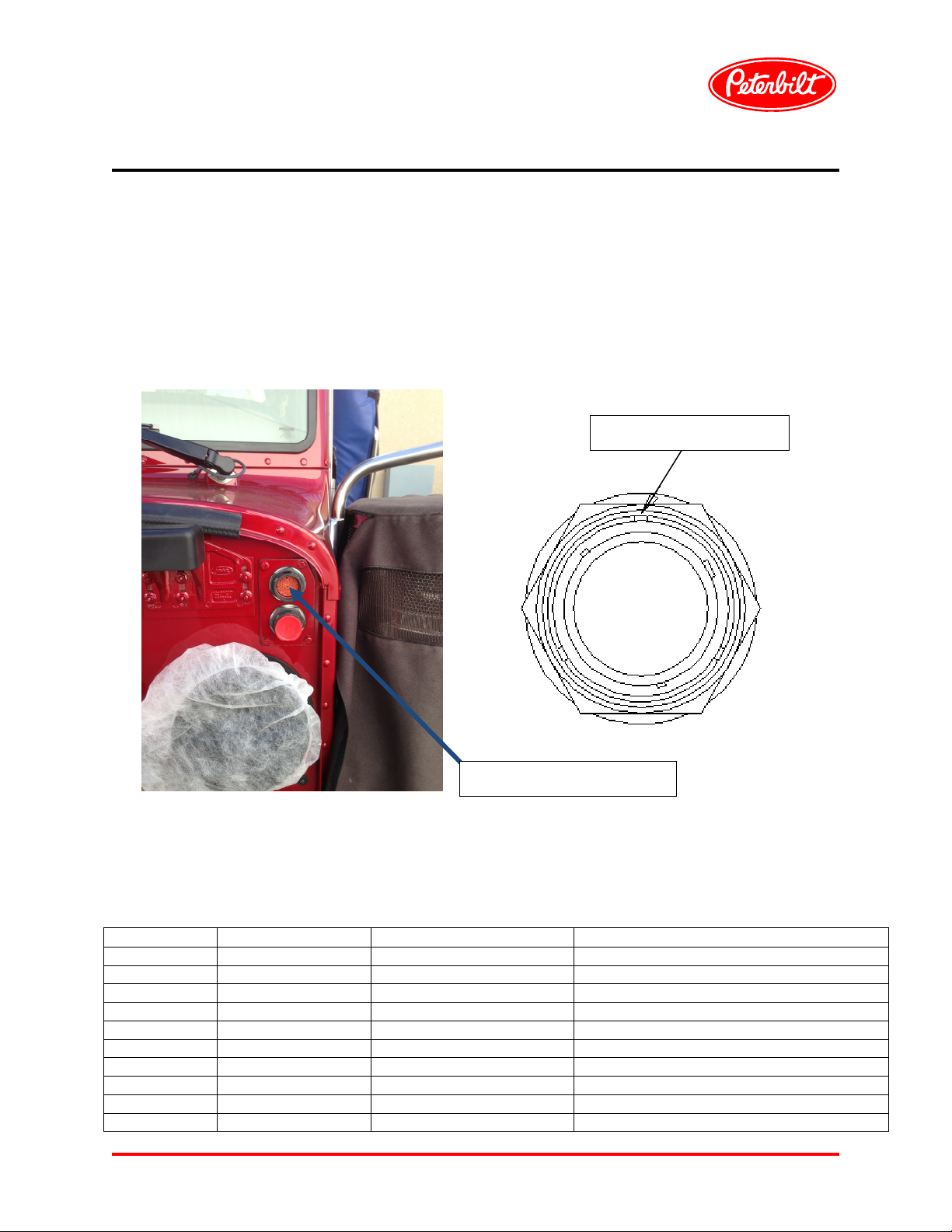
The interface between the vehicle’s main cab harness (ref. part # P92-8904) and the engine
harness is through the engine firewall connector located on the top edge of the driver side firewall.
Connector Assembly Key
Connector Information
The mating connector for the firewall connection is a Deutsch: HDP-26-24-47-E-L017. The firewall
connector pin-out is:
Pin Position Circuit Name Circuit Type Circuit Details
1 ORN1229-4 Power Ignition Switched Power
2 Open
3 BRN4331-0 Signal OBD MIL Light (Check Engine) 2013 Only
4 YEL7111-0 Signal A/C Compressor Clutch
5 ORN3971-0 Power AECU Ignition (2010 Engines and On)
6 BLK0782-0 Power Engine Spare Power (E1)
7 BLU4527-1 Signal Outside Air Temp
8 VIO4500-1 Power NAMUX Power (+5V)
9 Open
10 GRA3911-0 Signal Starter Solenoid Coil
PAGE 1 of 4
Engine Firewall Connector
Page 2

Engine Interface Guide
- Glider kits
11 GRA3143-0 Signal Remote Throttle Enable
12 VIO3141-0 Signal Throttle Supply #1 (+5V)
13 VIO3142-0 Signal Throttle Supply #2
14 BLU3142-1 Signal Throttle Sense Position #2
15 Open
16 GRA3631-1 Signal Two Speed Axle
17 GRA3186-0 Signal Misc. Engine Input #1
18 GRA3511-1 Signal PTO On/Off
19 Open
20 Open
21 ORN3111-1 Power Engine ECM Switched Power
22 BLU3141-0 Signal Throttle Sense Position #1
23 GRN3141-0 Signal Throttle Return #1
24 GRN4500-1 Signal NAMUX Analog Return
25 GRN4522-0 Signal Main Trans Oil Temp Return
26 BLU4522-2 Signal Main Trans Oil Temp
27 Open
28 WHT0813-1 Ground Shield J1939 BCAN – Shield (2013 Only)
29 GRN0813-0 Signal J1939 BCAN – Low (2013 Only)
30 GRN0812-1 Signal J1939 VCAN - Low
31 YEL0812-1 Signal J1939 VCAN - High
32 GRA3124-0 Signal MAG Switch
33 GRA3913-0 Signal Remote Start/Run
34 GRN3155-26 Signal Switch Common Return #3
35 Open
36 Open
37 GRA3512-0 Signal Remote PTO Set
38 GRA3513-0 Signal Remote PTO Resume
39 BLU3144-0 Signal Remote Throttle Signal
40 BRN4323-0 Signal Wait To Start Lamp
41 GRN3142-0 Signal Throttle Return #2
42 BRN4311-0 Signal Check Engine Telltale
43 BRN4312-0 Signal Stop Engine Telltale
44 YEL0813-0 Signal J1939 BCAN – High (2013 Only)
45 GRA3182-1 Signal Misc. Engine Output #2
46 YEL5913-0 Power Washer Pump
47 GRA3199-0 Signal Engine Multifunction Circuit #2
Notes:
The 2013 equipped cab no longer supports the J1587 interface (formally pins 2 and 3). The BCAN
circuits (pins 28, 29 and 44) are not needed for non-2013 engines. The NAMUX Power (+5V) circuit
has moved from pin 28 to pin 8. The misc. engine output #1 circuit has moved from pin 9 to 17. The
misc. engine output #2 circuit has moved from pin 41 to 45. The service brake switch #1 circuit
(formally pin 20) is now a multiplexed signal.
PAGE 2 of 4
Page 3

Engine Interface Guide
- Glider kits
Multiplexed Signals
The following items are supported by multiplexing using the J1939 connection between the cab
electrical controller (CECU) and the engine controller. Please make sure the engine parameters are
set to receive multiplexed signals for the following:
Engine Brake Controls
Cruise Controls
Engine Fan
Service Brake Pedal Position #1
The following signals for the instrumentation system come from the engine controller:
Engine Speed
Vehicle Speed
Oil Pressure
Coolant Temperature
Oil Temperature
Engine Hours
Vehicle Software Parameters
For proper functionality, please set the vehicle parameters as follows using ESA:
Make sure to set engine make to the proper engine (for DDEC use CAT)
Outside Air Temperature (OAT) is set to: SENSOR
RPM sweet spot set to: OFF
Water-in-Fuel sensor set to: OFF
Brake lamps on with retarder set to: OFF
DPF functionality set to: OFF
DEF gauge is set to: OFF
Clutch switch set to: OFF
Engine shutdown protection timer set to: OFF
Downhill speed limiter telltale set to: OFF
Engine de-rate and shutdown warnings set to: OFF
Green House Gas (GHG) set to: OFF
PTO total fuel used diagnostic set to: OFF
PAGE 3 of 4
Page 4

Engine Interface Guide
- Glider kits
OAT Sensor
The outside air temperature (OAT) sensor is set to connect to the engine for 2013 where the engine
reports back to the instrumentation as a multiplexed signal. Since older engines will not be able to
support this functionality, if the outside air temp feature is to be enabled, it must be hard wired to the
Cab Electrical Control Unit (CECU). The sensor is located in the driver side mirror head and the
circuit is available at the firewall engine connector in pin 7.
The OAT signal has to connect from the outside air temperature sensor to the cab electronic control
unit CECU (pin 16). Therefore, a means to connecting this circuit is to connect the OAT circuit from
the sensor to pin 7 of the firewall connector mentioned above. That circuit would then have to be
connected to pin 16 of the Main Cab harness CECU connector #3, located behind the dash (lower,
center areal. See below for excerpt from main cab harness drawing indicating the connector pin
location.
CECU Connector #3
PAGE 4 of 4
 Loading...