


TOTAL STATION
V-300SERIES
V-325 | V-325N | V-335N | V-323N
QUICK
REFERENCE
GUIDE
BASIC PROCEDURES
FOR V-300
AND POWERTOPOLITE
OPERATING PROCEDURE
FOR V-300
PENTAX Industrial Instruments Co., Ltd.
2-36-9, Maeno-cho
Itabashi-ku, Tokyo 174-0063 Japan Tel. +81 3 3960 0502
Fax +81 3 3960 0509
E-mail: international@piic.pentax.co.jp Website: www.pentaxsurveying.com

Electronic Total Station
Quick Reference Guide
Basic Procedures
for V-300
and
PowerTopoLite
Operating Procedure
PENTAX Industrial Instruments Co., Ltd.


CONTENTS
General |
|
8 |
Instruction Manuals |
8 |
|
Precautions regarding safety |
8 |
|
Warning |
8 |
|
Usage Precautions |
9 |
|
|
|
|
I Basic Procedures for V-300 |
|
|
|
|
|
1 Basic Operation |
10 |
|
1.1 |
Removing the Battery |
10 |
1.2 |
Attaching the Battery |
10 |
1.3 |
Turning the Power On and Off |
10 |
1.4 |
Angle Measurement |
10 |
|
1.4.1 Horizontal Angle |
10 |
|
1.4.2 Vertical Angle |
11 |
1.5 |
Distance Measurement |
11 |
|
1.5.1 Select your target |
11 |
|
1.5.2 Distance Measurement |
11 |
|
1.5.3 Changing Target constants |
11 |
|
1.5.4 Input Temperature and Atmospheric pressure |
12 |
|
1.5.5 Laser pointer |
12 |
|
1.5.6 Adjusting LCD contrast |
12 |
|
1.5.7 Adjusting Illumination brightness |
13 |
|
|
|
2 Changing Instrument Settings |
13 |
|
|
|
|
3 Basic Field Checking Procedures |
15 |
|
3.1 |
Laser Pointer |
15 |
3.2 |
Warning and Error Messages |
16 |
3.3 |
Atmospheric Correction |
17 |
|
|
|
4 Specifications |
18 |
|
Notice to the user of this product |
19 |
|
>>
5

CONTENTS
>>
II PowerTopoLite Operating Procedure
1 |
Starting Special Function |
21 |
|
|
|
|
|
2 |
Creating / Selecting a Job File |
21 |
|
|
|
|
|
3 |
Input a Known Point Coordinate |
21 |
|
|
|
|
|
4 |
Rectangular Coordinate Measurement |
22 |
|
|
4.1 |
Station Point Setup |
22 |
|
4.2 |
Orientation (Station Point H. Angle Setup) |
23 |
|
4.3 |
Measurement |
24 |
|
4.4 |
Offset Measurement |
25 |
|
4.5 |
Remote Measurement |
25 |
|
|
|
|
5 |
Polar Coordinate Measurement |
26 |
|
|
5.1 |
Station Point Setup |
26 |
|
5.2 |
Orientation (Station Point H. Angle Setup) |
27 |
|
5.3 |
Measurement |
27 |
|
5.4 |
Offset Measurement |
28 |
|
|
|
|
6 |
Free Stationing |
29 |
|
|
6.1 |
Known Point Setup |
29 |
|
6.2 |
Measurement |
29 |
|
6.3 |
Calculation |
29 |
|
|
|
|
7 |
Stake Out |
30 |
|
|
7.1 |
Station Point Setup |
30 |
|
7.2 |
Orientation (Station Point H. Angle Setup) |
30 |
|
7.3 |
Stakeout Point Setup |
31 |
|
7.4 |
Stakeout Measurement |
31 |
|
|
|
|
8 |
Stake Out (Point to Line) |
32 |
|
|
8.1 |
Station Point Setup |
32 |
|
8.2 |
Orientation (Station Point H. Angle Setup) |
32 |
|
8.3 |
Point A Setup |
33 |
|
8.4 |
Point B Setup |
33 |
|
8.5 |
Point to Line Measurement |
33 |
>>
6

CONTENTS
>>
9 Traverse Measurement |
34 |
|
9.1 |
Measurement at the Start Point |
35 |
9.2 |
Measurement at a Corner Point |
36 |
9.3 |
To Finish the Traverse Measurement |
37 |
9.4 |
Traverse Calculation |
37 |
10 |
Cogo |
38 |
|
Calculation Parameters and Output |
39 |
|
|
|
11 |
Area Calculation |
40 |
|
|
|
12 |
3D Surface and Volume Calculation |
40 |
|
|
|
13 |
REM (Remote Element Measurement) |
41 |
|
|
|
14 |
RDM (Remote Distance Measurement) |
42 |
|
|
|
15 VPM (Virtual Plane Measurement) |
42 |
|
|
|
|
16 |
Changing Preference |
43 |
|
Preference List |
44 |
7
Instruction Manuals
Quick Reference Guide is intended to provide a quick reference in the field. For ease of use in the field, the following Quick Reference Guide booklets are provided in the carrying case.
1.Basic procedure
2.PowerTopoLite Operating procedure
The complete instruction manuals are contained on the CD that is attached to each V-300.
This guide uses the symbol “ xN” as an expression of repeating times of key operation. For example. “ 
 x2” means that [ESC] key is pressed two times.
The symbol “+”expresses that multiple keys are pressed simultaneously.
PRECAUTIONS REGARDING SAFETY
Before using this product, be sure that you have thoroughly read and understood the instruction manual that is included in the attached CD-ROM to ensure proper operation.
WARNING
Solar Observation
Never view the sun directly using the telescope as this may result in loss of sight.
Laser Safety
V-300 is a class-II (2) Laser product. Avoid direct eye exposure. Do not stare into laser beam.
V-325 is Class II(2) and V325N/V335N/V323N are Class IIIR Laser product. Avoid direct eye exposure. Do not stare into laser beam.
8

Electro-Magnetic Compatibility (EMC)
This instrument complies with the protection requirement for residential and commercial areas. If this instrument is used close to industrial areas or transmitters, the equipment can be influenced by electromagnetic fields.
Risk of Explosion
Do not use this product in a location where there is coal dust, or near flammable material as there is a risk of explosion.
USAGE PRECAUTIONS
Target Constant
Confirm the Target Constant of the instrument before measurement.
Reflectorless and Reflecting sheet
The reflectorless measurement range may vary depending on the target and surrounding brightness.
In case the reflectorless measurement results in low accuracy, perform the distance measurement by Prism.
Battery & Charger
Use the battery charger that is suitable to the battery you are using. If water should happen to splash on the instrument or the battery, wipe it off immediately and allow it to dry in a dry location.
9
I Basic Procedures for V-300
1. Basic Operation
1.1Removing the Battery
(1)Rotate the knob above the battery pack counter-clockwise.
(2)Lift up the battery pack and remove it from the instrument.
1.2Attaching the Battery
(1)Place the channel on the bottom of the battery pack, onto the protrusion of the instrument and push the battery pack down into place.
(2)Turn the knob clockwise.
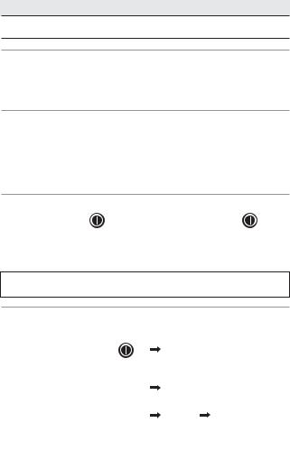
1.3Turning the Power On and Off
To set power on : |
To shut down : |
To turn the power supply off, press the I/O key for more than 1 second and then release it. Power turns OFF.
NOTE: The power is automatically turned off after 10 minutes of inactivity (Factory default setting).
1.4 Angle Measurement |
|
|
|
|
|
|
|
|
1.4.1 Horizontal Angle |
|
|
|
|
|
|
|
|
Set the screen MODE A : |
|
|
MODE A screen |
|||||
Control keys for measuring horizontal angle: |
||||||||
To set the angle to 0 |
: |
|
|
|
|
|
|
|
|
|
|
|
|
|
|
||
|
|
|
|
|
||||
|
|
|
|
|
||||
To hold the angle |
: |
|
|
|
|
|
|
|
|
|
|
|
|
|
|
||
|
|
|
|
|
|
|
||
|
|
|
|
|
|
|||
To release HOLD |
: |
|
|
|
|
|
|
|
|
|
|
|
|
|
|
||
|
|
|
|
|
|
|
||
|
|
|
|
|
|
|
||
|
|
|
|
|
|
|
|
|
10
To input an angle |
: |
|
|
|
|
||
|
|
||
input value by using: |
|
|
|
|
, |
||
|
|||
|
|||
|
|||
|
|
|
|
To read clockwise angle : 

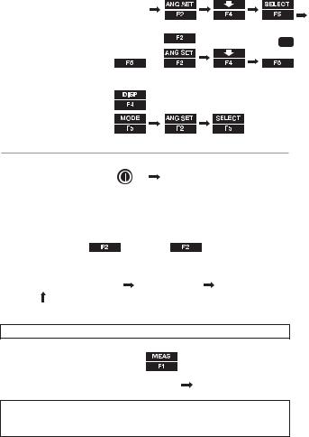
1.4.2 Vertical angle
To display vertical angle :
To read the slope % :
 ,
, 

 ,
,


x2 
1.5 Distance Measurement |
|
Set the screen MODE A: |
MODE A screen |
1.5.1 Select your target
Select target type (measurement mode): In case of V-325:
(Reflecting sheet) 
 (Prism)
 (Reflecting Sheet)
In case of V-325N/V-335N/V323N:
(Reflecting sheet) |
|
|
|
(Prism) |
|
(Reflectorless) |
||||
|
|
|||||||||
|
|
|||||||||
|
|
|
|
|
|
|
|
|
|
|
|
|
|
|
|
|
|
|
|
|
|
|
|
|
|
|
|
|
|
|
|
|
|
|
|
|
|
|
|
|
|
|
|
|
|
|
|
|
|
|
|
|
|
|
NOTE: The selected target is maintained until next time you change.
1.5.2 Distance measurement
For a single shot measurement:
For tracking measurement |
: |
|
|
|
|
|
|
||
|
|
|
|
|
NOTE: The number of shots can be defined.The default is
“one time”.The measuring modes activated by the above operations can be also changed.
11
1.5.3 Changing Target constants
The default constants are:
Prism |
: -30mm |
Reflector-less |
: always 0mm (V-323N,V-325N,V-335N) |
Sheet |
: 0mm |
Before changing the constants, set Target Constant in the Initial Setting to“INPUT” mode:
+ |
|
|
|
|
|
x2 |
|
|
|
|
x2 |
x3 |
|
|
|
|
|
|
|
|
|
|
|||||
|
|
|
|
|
|
|
|
|
|
|
|||
To change Prism constant: |
|
|
|
|
|
|
|
|
|
|
|
||
|
|
|
|
|
|
|
|
|
|
|
|||
|
|
|
|
|
|
|
|
|
|
|
|||
|
|
|
|
|
|
|
|
|
|
|
|||
input value |
|
|
|
|
|
|
|
|
|
|
|
|
|
|
, |
|
, |
|
|
, |
|
|
x2 |
||||
|
|
|
|
|
|
||||||||
by using : |
|
|
|
|
|
|
|||||||
|
|
|
|
|
|
|
|
|
|
|
|
||
1.5.4 Input Temperature and Atmospheric pressure
The default atmospheric correction mode is “ATM INPUT”. Before manual input, change the default mode to “ppm INPUT” :

 +
+ 


 x2
x2 


 x2
x2
To Input temperature |
: |
|
|
|
|
|
|
|
|
|
|
|
x2 |
|
|
|
|
|
|
|
|
|
|
|
|
|
|
|
|
|
|||||
|
|
|
|
|
|
|
|
|
|
|
|
|
|
|
|
||
|
|
|
, |
|
, |
|
|
|
, |
|
|
|
|
x2 |
|||
input value by using: |
|
|
|
|
|
|
|
|
|
|
|||||||
|
|
|
|
|
|
|
|
|
|||||||||
To Input atmospheric pressure: |
|
|
|
|
|
|
|
|
|
|
|
|
|
|
|||
|
|
|
|
|
|
|
|
|
|
|
|
|
x3 |
|
|
||
|
|
|
|
|
|
|
|
|
|
|
|
|
|
|
|||
|
|
|
|
|
|
|
|
|
|
|
|
|
|
||||
|
|
|
|
|
|
|
|
|
|
|
|
|
|
|
|
|
|
|
|
|
, |
|
|
, |
|
|
|
|
x2 |
||||||
input value by using: |
|
, |
|
|
|
|
|
|
|
||||||||
|
|
|
|
|
|
|
|||||||||||
1.5.5 Laser pointer |
|
|
|
|
|
|
|
|
|
|
|
|
|
|
|
|
|
To activate Laser pointer |
: |
|
|
|
|
|
|
|
|
|
|
|
|
|
|
|
|
To quit Laser pointer |
: |
|
|
|
|
|
|
|
|
|
|
|
|
|
|
|
|
NOTE: The laser pointer is kept activated until it is deactivated by the above procedure.
12
1.5.6 Adjusting LCD contrast
+ |
|
|
|
or |
|
|
|
|
|
||
|
|
|
|
||
|
|
|
|
|
|
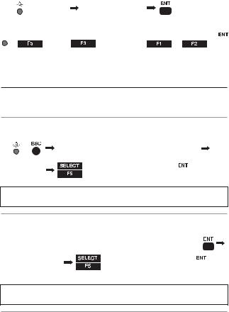
1.5.7 Adjusting Illumination brightness

 +
+  for LCD
  (for Reticle)
 or
or 

2. Changing Instrument Settings
You can change the instrument settings by “HELP” menu or by inputting “007” code.
2.1 Help menu
While the screen is in MODE A or MODE B,
+ |
Select a desired item by |
|
or |
|
|
|
|||
|
|
|
|
|
 Change the setting

NOTE: Some items have sub-menus where the selecting procedure by using F1 - F4 is again repeated.
2.2 “007” code
While the screen is in MODE A or MODE B, 


 Input 007 code by using


 Change the setting
 x2
x2
NOTE: Some items have sub-menus where the selecting procedure by using F1 - F4 is again repeated.
2.3 Instrument setting items
See chart on page 14
13

14
007 code |
HELP menu list |
|
Default |
Other options |
|
||||
401 |
TARGET CONST |
PRISM CONST |
-30mm |
0mm, INPUT |
|
|
SHEET CONST |
0 mm |
INPUT |
402 |
ATM CORR |
|
ATM INPUT |
ppm INPUT, NIL |
502 |
SHOT COUNT |
SHOT CONT |
1 time |
3 times, 5 times, INPUT |
|
|
SHOT INPUT |
01 times |
(input) |
503 |
CRV/REF CORR |
|
0.14 |
0.2, NIL |
504 |
MIN UNIT ANG. |
|
COARSE |
FINE |
505 |
V. ANG. STYLE |
|
Z.0 |
H.0, COMPASS |
509 |
QUAD BUZ |
|
OFF |
ON |
510 |
AUTO OFF |
|
10 MIN |
20 MIN, 30 MIN, NIL |
511 |
EDM OFF |
|
ON |
OFF |
517 |
COMPENSATOR |
|
ON |
OFF |
522 |
QUICK MEASURE |
|
OFF |
ON |
523 |
ATM CORR DISP |
|
ON |
OFF |
701 |
ATM UNIT |
TEMP.UNIT |
Centigrade |
Fahrenheit |
|
|
PRESS UNIT |
hPa |
mmHg, inchHq |
702 |
DIST.UNIT |
|
m |
ft+inch, ft |
703 |
ANG.UNIT |
|
DEG |
DEC, GRD, MIL |
801 |
SET UP COM. |
BAUD RATE |
1200 |
2400 4800 9600 |
|
|
DATA LENGTH |
8 |
|
|
|
PARITY BITS |
NIL |
EVEN, ODD |
|
|
STOP BITS |
1 |
2 |
|
|
SIGNAL CONTROL |
ON |
OFF |
|
|
XON/XOFF |
ON |
OFF |
|
|
THROUGHT COMMAND |
NIL |
a,b,c,d,e,f |
V-325N, V-335N, V-323N |
|
|
|
|
521 |
REF. LESS RANGE |
REF. LESS RANGE |
NORMAL |
LONG |
|
|
LONG RANGE MES. |
ON |
OFF |
|
|
LONG RANGE SETUP |
EACH TIME |
PERMANENT |

3. Basic Field Checking Procedures
Checks and Adjustments should be performed before and during measurement.
3.1 Laser Pointer
To activate the laser pointer:
Check if the projected laser spot points at the same position that is aimed by the center of the cross-hair line of the telescope.
To adjust the laser pointer: Consult your local dealer.
15

3.2 Warning and Error Messages
Warning Message |
Meaning |
What to do |
Out of tilt range |
Displayed when the instrument is til- |
|
ted beyond the vertical compensation |
|
range (±3’) in case 1 axis or 2 axis |
|
automatic compensation is selected. |
|
This message may be temporarily dis- |
|
played if the instrument is turned too |
|
fast. |
Re-level the instrument. Repair is needed if the message is displayed when it is properly leveled.
Excess data |
The input data exceeds the allowable |
|
range. |
Press the [ESC] key and enter the correct data.
Mismatched |
• This message is displayed if a long |
Select the correct target |
Target |
distance which is a far beyond |
mode. |
|
measurable distance of V-300 |
|
|
series is measured with a wrong |
|
|
target mode. |
|
|
Please select a correct target then |
|
|
measure. |
|
|
If a wrong target is selected, a |
|
|
correct distance cannot be |
|
|
measured. |
|
|
|
|
Target is too |
• The measurement distance is less |
Select a longer point, |
close. |
than 1.5m in Reflector sheet mode. |
or use a tape measure. |
|
• The measurement distance is less |
|
|
than 1.5m in Prism mode. |
|
|
|
|
Unsuitable |
• Under too strong sun light. |
Condition |
• Unstable light value owing to |
|
shimmer or obstacles. |
|
• Target and Prism do not face |
|
the instrument. |
|
• Target and Prism are not correctly |
|
sighted. |
|
• Measurement range is over in |
|
Reflectorless mode. |
|
• Sufficient signal does not return by |
|
sighting sharp edge etc. at |
|
Reflectorless mode. |
Change the object that has much better reflectivity, or wait until the sun activity
has weakened.
16
 Loading...