


TOTAL STATION
V-300SERIES
V-325 | V-325N | V-335N | V-323N
INSTRUCTION
MANUAL
V-300 SERIES
PowerTopoLite
PENTAX Industrial Instruments Co., Ltd.
2-36-9, Maeno-cho
Itabashi-ku, Tokyo 174-0063 Japan Tel. +81 3 3960 0502
Fax +81 3 3960 0509
E-mail: international@piic.pentax.co.jp Website: www.pentaxsurveying.com

Before using this product, be sure that you have thoroughly read and understood this instruction manual to ensure proper operation.
After reading this manual, be sure to keep in a convenient place for easy reference.
Copyright © 2005 PENTAX Industrial Instruments Co., Ltd.
All Rights Reserved
PENTAX Industrial Instruments Co., Ltd. is a sole proprietor of the PowerTopoLite software.
The PowerTopoLite software and publication or parts thereof, may not be reproduced in any form, by any method, for any purpose.
PENTAX Industrial Instruments Co., Ltd. makes no warranty, expressed or implied, including but not limited to any implied warranties or merchantability or fitness for a particular purpose, regarding these materials and makes such materials available.
CONTENTS
COPYRIGHT |
2 |
||
CONTENTS |
3 |
||
DISPLAY AND KEYBOARD |
6 |
||
OPERATION KEY |
6 |
||
FUNCTION KEY |
7 |
||
DISPLAY COMBINATION OF MODE A OR MODE B |
9 |
||
ALPHANUMETRIC INPUT |
9 |
||
1. |
INTRODUCTION |
10 |
|
|
1.1 |
Introduction |
10 |
|
1.2 |
Before using the PowerTopoLite manual |
11 |
2. |
ACCESSING POWERTOPOLITE |
13 |
|
|
2.1 |
How to access PowerTopoLite |
13 |
|
2.2 |
Allocation of each PowerTopoLite Function key |
15 |
|
2.3 |
Typical Function keys of PowerTopoLite |
17 |
3. |
FILE MANAGER |
18 |
|
|
3.1 |
Information of the remaining memory available |
18 |
|
3.2 |
Creation of a new Job |
19 |
|
3.3 |
Selection of a Job name |
20 |
|
|
3.3.1 Selection of a Job |
20 |
|
|
3.3.2 Selection by a Job name input |
21 |
|
3.4 |
Deletion of a Job name |
22 |
|
|
3.4.1 Deletion from a Job list |
22 |
|
|
3.4.2 Deletion from a Job name search |
23 |
|
3.5 |
All Clear |
24 |
4. |
MEASURE |
25 |
|
|
4.1 |
Station setup [By Rectangular Coordinates] |
26 |
|
|
4.1.1 Point name, PN, input |
27 |
|
|
4.1.2 Coordinates, X, Y, Z, IH, and PC input |
27 |
|
4.2 |
Station Orientation |
32 |
|
|
4.2.1 Station orientation |
33 |
|
4.3 |
Measuring |
34 |
|
4.4 |
Point Code |
35 |
|
4.5 |
Remote, Offset, Station, and H. angle function |
38 |
|
|
4.5.1 Remote |
38 |
|
|
4.5.2 Offset |
40 |
|
|
4.5.3 Station |
42 |
|
|
4.5.4 H. angle |
42 |
3
|
4.6 |
Station setup [ By Polar Coordinates] |
43 |
|
|
|
4.6.1 Point name, PN, input |
44 |
|
|
|
4.6.2 IH, TEMP, PRESS, ppm and PC input |
44 |
|
|
4.7 |
Station Orientation |
46 |
|
|
4.8 |
Measuring |
47 |
|
|
4.9 |
Offset |
49 |
|
5. |
VIEW AND EDIT |
51 |
||
|
5.1 |
Graphical View |
51 |
|
|
5.2 |
Create the Rectangular Point |
52 |
|
|
5.3 |
Edit the Data |
54 |
|
6. |
FREE STATIONING |
56 |
||
|
6.1 |
Stationing by more than 3 known points |
57 |
|
|
6.2 |
Stationing by two known points |
60 |
|
7. |
STAKE OUT |
64 |
||
|
7.1 |
Stake out |
64 |
|
|
7.2 |
Point to line |
69 |
|
8. |
CALCULATIONS |
74 |
||
|
8.1 |
COGO |
74 |
|
|
|
8.1.1 Inverse |
74 |
|
|
|
8.1.2 Point Coordinates |
80 |
|
|
|
|
8.1.2.1 Point Coordinates, Distance and H. angle |
81 |
|
|
|
8.1.2.2 Distance and H. angle |
86 |
|
|
|
8.1.2.3 H. angle input |
87 |
|
|
8.1.3 Circle Radius |
89 |
|
|
|
8.1.4 |
Line-Arc Intersection |
92 |
|
|
8.1.5 |
Line-line Intersection |
96 |
|
|
8.1.6 Arc-Arc intersection |
100 |
|
|
|
8.1.7 Distance offset |
104 |
|
|
|
8.1.8 Point distance offset |
108 |
|
|
|
8.1.9 Arc distance offset |
111 |
|
|
8.2 |
2D Surface |
116 |
|
|
8.3 |
3D Surface and Volume |
120 |
|
|
8.4 |
REM |
|
125 |
9 |
VPM (Virtual Plane Measurement) |
127 |
||
10 |
RDM (Remote Distance Measurement) |
132 |
||
|
10.1 PH input |
133 |
||
|
10.2 Reference point - Target distance |
133 |
||
|
10.3 TargetTarget distance |
134 |
||
|
10.4 New Reference point selection |
135 |
||
4
11. TRAVERSE |
136 |
|
11.1 |
Start point measuring |
138 |
11.2 |
Corner point measuring |
143 |
11.3 |
Calculation |
146 |
12. INPUT / OUTPUT |
149 |
|
12.1 |
Input from the PC |
149 |
12.2 |
Output to the PC |
151 |
12.3 |
Communication setup |
153 |
|
12.3.1 Receiving data setting |
153 |
|
12.3.2 Sending data setting |
156 |
12.4 |
About DataLink DL01 Software |
158 |
13. PREFERENCE |
162 |
|
13.1 |
Language selection |
163 |
13.2 |
Coordinate axis definition |
163 |
13.3 |
Input method selection |
166 |
13.4 |
Action method selection |
168 |
13.5 |
Remote method selection |
169 |
13.6 |
Compare method selection |
171 |
13.7 |
Request aiming selection |
172 |
13.8 |
EDM settings selection |
173 |
13.9 |
Elevation Factor |
174 |
13.10 |
Duplicate Point Check |
175 |
5
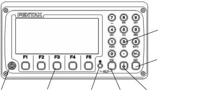
DISPLAY AND KEYBOARD
•Basic display and keyboard of V-300 series are described below, and the
function keys of PowerTopoLite are described at “2. ACCESSING POWERTOPOLITE”.
Alphanumeric and +/- key
Enter key
Power supply key Function key Illumination key ESC key Laser key
OPERATION KEY
Key |
Description |
[POWER] |
ON/OFF of power supply |
[ESC] |
Returns to previous screen or cancels an operation. |
[ILLUMINATION] |
Turns the illumination of the LCD display and telescope reticle on |
|
and off. |
[ENT] |
Accepts the selected (highlighted) choice or the displayed screen |
|
value. |
[LASER] |
ON/OFF of Laser Pointer |
[Alphanumeric] |
At the numerical value screen, the numerical value and the sign “.” |
|
displayed are input.The English characters printed right under |
|
numeric of each key are input. |
[HELP] |
Pressing [lLLU]+[ESC] causes a help menu to appear in |
|
A MODE or B MODE or causes a help message to appear. |
6

FUNCTION KEY
Display |
F. Key |
Description |
• MODE A |
|
|
[MEAS] |
F1 |
Pressing this key one time measures the distance in |
|
|
normal mode (another measurement type can be selected |
|
|
by Initial Setting 2.) |
[MEAS] |
F1 |
Pressing this key twice measures the distance in coarse |
|
|
mode (another measurement type can be selected by |
|
|
Initial Setting 2. ) |
[TARGET] |
F2 |
Toggles the target type between SHEET/PRISM/REFLECTRLESS |
[0 SET] |
F3 |
Resets the horizontal angle to 0° 0’ 0”by pressing twice. |
|
|
only V-325N,V-335N,V-323N |
[DISP] |
F4 |
Switches the display composition in the order |
|
|
“H.angle / H.dst. / V.dst.”, “H.angle / V.angle / S.dst.”and |
|
|
“H.angle / V.angle / H.dst. / S.dst. / V.dst.” |
[MODE] |
F5 |
Switches the screen between MODE A and MODE B. |
• MODE B |
|
|
[S.FUNC] |
F1 |
PowerTopoLite Special Functions |
[ANG SET] |
F2 |
Brings up the angle setting screen for setting angle-related |
|
|
parameters |
|
|
(H.ANGLE / %GRADE, H.ANGLE INPUT and R/L REVERSE). |
[HOLD] |
F3 |
Pressing this key twice retains (holds) the horizontal angle |
|
|
shown on the display. |
[CORR] |
F4 |
Brings up the screen for changing the target constant, |
|
|
temperature. |
|
|
Pressure setting. |
[MODE] |
F5 |
Toggles the screen between MODE A and MODE B. |
7
• Other functions
[ |
] |
F1 |
Moves the cursor to the left. |
[ |
] |
F2 |
Moves the cursor to the right. |
[ |
] |
F1 |
Goes back five items on the screen. |
[ |
] |
F2 |
Goes forward five items on the screen. |
[ |
] |
F3 |
Moves the cursor up. |
[ |
] |
F4 |
Moves the cursor down. |
[RETICLE] |
F3 |
Changing the reticle illumination when pressing |
|
|
|
|
illumination key. |
[LCD] |
F4 |
Changing the LCD contrast when pressing |
|
|
|
|
illumination key. |
[ILLU] |
F5 |
Changing the LCD illumination when |
|
|
|
|
pressing illumination key. |
[CLEAR] |
F5 |
Clear the figure. |
|
[SELECT] |
F5 |
Open the selection window. |
|
|
|
|
|
•The Function keys of each PowerTopoLite function are described at “2. ACCESSING POWERTOPOLITE” and at the each function.
8

DISPLAY COMBINATION OF MODE A OR MODE B
Function |
MODE A |
MODE B |
F1 |
MEAS |
S.FUNC |
F2 |
TARGET |
ANG SET |
F3 |
0 SET |
HOLD |
F4 |
DISP |
CORR |
F5 |
MODE |
MODE |
• Mode A or Mode B is switched by pressing [F5] [MODE].
ALPHANUMERIC INPUT
The point name etc. is input by the alphanumeric keys as following.
Key |
Letter under key |
Letter & figure order to input |
|
[0] |
|
[@][.][_][-][:][/][0] |
|
[1] |
PQRS |
[P][Q][R][S][p][q][r][s][1] |
|
[2] |
TUV |
[T][U][V][t][u][v][2] |
|
[3] |
WXYZ |
[W][X][Y][Z][w][x][y][z][3] |
|
[4] |
GHI |
[G][H][I][g][h][i][4] |
|
[5] |
JKL |
[J][K][L][j][k][l][5] |
|
[6] |
MNO |
[M][N][O][m][n][o][6] |
|
[7] |
|
_ |
_ |
|
[ ][?][!][_][ |
][ ][|][&][7] |
|
[8] |
ABC |
[A][B][C][a][b][c][8] |
|
[9] |
DEF |
[D][E][F][d][e][f][9] |
|
[.] |
|
[.][,][:][;][#][(][)] |
|
[+/-] |
|
[+][-][*][/][%][=][<][>] |
|
|
|
|
|
9

1. INTRODUCTION
1.1 Introduction
Thank you for your first looks at PowerTopoLite by reading this manual.
The PowerTopoLite is a user friendly data collection and calculation program for the PENTAX total station V-300 series.
PowerTopoLite is developed based on PowerTopo, which is known as versatile on-board software for PENTAX ATS total station series. The optimum combination of PowerTopoLite and V-300 hardware makes PowerTopoLite as an easy and useful fieldwork tool.
The icon based main menu offers you the following possibilities.
•FILE MANAGER
•MEASURE
•VIEW AND EDIT
•FREE STATIONING
•STAKE OUT
•CALCULATIONS
•VIRTUAL PLANE MEASUREMENT
•REMOTE DISTANCE MEASUREMENT
•TRAVERSE
•TRANSFER
•PREFERENCE
10
1.2 Before using the PowerTopoLite manual
•Memories in the instrument
The series instrument incorporates not only the PowerTopoLite surveying programs as the Special function but also File manager and Data transfer programs.
The internal memory in the instrument can store the maximum 16000 point’s data in V-325, 30000 point’s data in V-325N, V-335N and V-323N.
•Relations between the Memory and each Function
Function |
|
Read from the stored data |
Write to the stored data |
|
||||
Measure |
|
SP, BSP |
|
|
SP, BSP, FP (SD) |
|
||
Stake Out |
|
SP, BSP, SOP |
|
|
SP, BSP, SOP, OP |
|
||
Point to Line |
|
SP, BSP, KP1, KP2 |
|
|
SP, BSP, KP1, KP2, OP |
|
||
Free Stationing |
Each KP |
|
|
Each KP, SP (CD) |
|
|||
Traverse |
|
SP, BSP |
|
|
SP, FP (SD) |
|
||
VPM |
|
SP, BSP, Each KP |
|
|
SP, BSP, Each KP, CP (CD) |
|
||
|
|
|
|
|
|
|
|
|
Station point: |
SP |
Foresight point: |
FP |
Backsight point: |
|
BSP |
Stakeout point: |
SOP |
|
|
|
|
|
|
|
|
|
Known point: |
KP |
End point: |
EP |
Observation point: |
OP |
Conversion data: |
CD |
|
|
|
|
|
|
|
|
|
|
Conversion point: |
CP |
Crossing point: |
CRP |
Surveyed data: |
|
SD |
|
|
|
|
|
|
|
|
|
|
|
11

•IH and PH
IH stands for “Instrument Height” and PH stands for “Prizm Height”.
•The PowerTopoLite manual mainly describes the V-300 special functions,
and the basic operations are described in the (basic) V-300 manual. And, therefore, refer to the V-300 basic manual regarding the V-300 general instrument operations.
The PowerTopoLite screens vary with the selections of the “Preference”.
The factory default settings of the Preference are shown there. It is also possible to select “Process type” that takes over the functionality of “PowerTopoLite” or “Structure type” that takes over the functionality of our past product in ”Action Method Selection”.
•The V-300 series instrument has a Job name of “PENTAX” as its default setting. And, therefore, each data is stored in the “PENTAX” unless another new Job name is
created. When another Job name is created, each data is stored in the new Job name.
•The input range of the X, Y and Z Coordinate is “-99999999.998” - “99999999.998”.
•The input range of the Instrument and Prism height is “-9999.998” - “9999.998”.
•The PC, PointCodeList, is added to the PN, Coordinates X, Y, Z and IH (PH or HI) and you can input your desired attributes for the point. If you have PointCodeList in the job named “PointCodeList”, you can easily select one of the PointCode from the list or edit one of them after pressing [ENT]. Please, note that Point Code, which is saved in the other job can not be refered as a list.
•There are two Coordinates types of Rectangular and Polar.
The RO,VO,DO,TO offset and the remote measurement are possible when you select the Rectangular Coordinates.
The RO,DO offset is possible when you select the Polar Coordinates.
•When you measure in EDM SETTINGS of COARSE TRACKING, the V-300 displays a distance value to two decimal places. However, distance data of polar coordinates are displayed by EDIT function to three decimal places even, and sent to four decimal place. So, “0“ or “00” is added to the distance data after the third decimal point in COARSE TRACKING mode.
For example
Displayed value: 123.45
Displayed by EDIT: 123.450
Sent polar data: |
123.4500 |
•Rectangular coordinates is displayed, stored, and sent to three decimal place even if in COARSE TRACKING or FINE MEASURE mode.
•You can change the distance measurement mode during measuring operation by pressing the EDM key at the MEASURE and VPM functions.
•The same Point Name of the plural polar points can be saved.
12

2. ACCESSING POWERTOPOLITE
2.1 How to access PowerTopoLite
To access the V-300 Special Functions of the PowerTopoLite, perform the following procedures.
a.Press the Power (ON/OFF) key to view the V-300 start-up screen.
b.It turns to Mode A screen.
MODE A
H. angle 123° |
45’ |
25” |
|
H.dst |
|
|
|
V.dst |
|
|
|
|
|
|
|
MEAS TARGET |
0 SET |
DISP |
MODE |
|
|
|
|
c. Press the [F5][MODE] to view Mode B screen.
MODE B
H. angle 123° 45’ 25”
H.dst
V.dst
S. FUNC ANG SET |
HOLD |
CORR |
MODE |
|
|
|
|
13
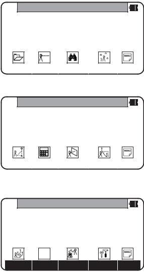
d. Press [F1][S.FUNC] to view Functions of PowerTopoLite screen.
PowerTopoLite
FILE |
MEAS |
VIEW |
FREE |
PAGE |
|
|
|
|
|
e. Press [F5][PAGE] to view another Function combination of PowerTopoLite screen.
PowerTopoLite
STAK |
CALC |
VPM |
RDM |
PAGE |
|
|
|
|
|
f. Press [F1][PAGE] to view another Function combination of PowerTopoLite screen.
PowerTopoLite
TRAV |
I/O |
PREF |
PAGE |
14

2.2 Allocation of each PowerTopoLite Function key
a. FILE, MEAS, VIEW, FREE, STAK, CALC, I/O and PREF functions
KEY |
Function |
Description |
F1 |
FILE |
File Manager |
F2 |
MEAS |
Measure |
F3 |
VIEW |
View and Edit |
F4 |
FREE |
Free stationing |
Other four Functions are viewed by pressing [F5][PAGE].
KEY |
Function |
Description |
F1 |
STAK |
Stake out |
F2 |
CALC |
Calculation |
F3 |
VPM |
Virtual Plane Measurement |
F4 |
RDM |
Remote Distance Measurement |
Other four Functions are viewed by pressing [F5][PAGE].
KEY |
Function |
Description |
F1 |
TRAV |
Traverse |
F2 |
|
N/A |
F3 |
I/O |
Input and Output |
F4 |
PREF |
Preference |
b. INVERSE, POINT COORDINATES, LINE-LINE INTERSECTION functions
CALCULATION screen is viewed by pressing [F2][CALC]. The CALCULATION consists of COGO, 2D SURFACE and 3D SURFACE & VOLUME functions.
CALCULATION
1.COGO
2.2D SURFACE
3.3D SURFACE & VOLUME
4.REM
COGO screen is viewed by selecting 1. COGO and pressing the [ENT].
15
The COGO consists of INVERSE, POINT COORDINATES, CIRCLE RADIUS LINE-ARC INTERSECTION, LINE-LINE INTERSECTION, ARC-ARC INTERSECTION, DISTANCE OFFSET, POINT DISTANCE OFFSET, ARC DISTANCE OFFSET, and functions.
COGO
1.INVERSE
2.POINT COORDINATES
3.CIRCLE RADIUS
4.LINE-ARC INTERSECTION
5.LINE-LINE INTERSECTION
COGO
5.LINE-LINE INTERSECTION
6.ARC-ARC INTERSECTION
7.DISTANCE OFFSET
8.POINT DISTANCE OFFSET
9.ARC DISTANCE OFFSET
16

2.3 Typical Function keys of PowerTopoLite
Following function keys are typical ones of PowerTopoLite and each function key is described for each function of this Manual.
KEY |
Description |
ENTER |
Opens the input screen of Coordinate values etc. |
PAGE |
Views another function combination. |
SELECT |
Selects the Character and moves to next input at PN |
|
input etc. |
ACCEPT |
Enters the displayed values without new Coordinates |
|
value input etc. |
INPUT |
Inputs your desired Horizontal angle. |
BSP |
Views the BSP SETUP screen to input its Coordinates. |
SAVE |
Saves inputted data. |
ME/SAVE |
Measures and then saves inputted data. |
EDIT |
Changes the Point name or Prism height. |
REMOTE |
Views your aiming point Coordinates. |
OFFSET |
Views the Target Coordinates adding the offset values. |
STATION |
Returns to the STATION POINT SETUP screen. |
H. ANGLE |
Returns to the STATION POINT H.ANGLE SETUP screen. |
LIST |
Views the POINT SELECTION FROM THE LIST screen. |
ZOOM ALL |
Returns to original size. |
ZOOM IN |
Magnifies the graphics size. |
ZOOM OUT |
Reduces the graphics size. |
DISP |
Views point or point & graphic or point & point name |
|
or all. |
DELETE |
Views the POINT DELETION screen. |
FIND PN |
Views the PN search screen by inputting the Point name. |
ADD |
Allow you to add more points for the free stationing. |
CALC |
Starts the calculation of the free stationing. |
NEXT |
Views the next known point Coordinates setup screen. |
DATA |
Views the TARGET POINT screen. |
TARGET |
Selects the Target type. |
EDM |
Selects the EDM settings. |
ALL |
Selects all points of current job. |
ORDER |
The order of selected points. |
17
3. FILE MANAGER
The Data storage memory status, creating a new Job name and the Selection and Deletion of a Job name are executed by this function.
From the PowerTopoLite screen, press [F1][FILE] to view the FILE MANAGEMENT screen.
FILE MANAGEMENT
1.INFORMATION
2.CREATE
3.SELECT
4.DELETE
5.ALL CLEAR
3.1Information of the remaining memory available
Press [ENT] to view INFORMATION screen.
INFORMATION
Memory free: 93 % Current job: PENTAX 1004 Point saved
The remaining memory available and a JOB name PENTAX are viewed on the screen. The Job name “PENTAX” is a default setting.
18
3.2 Creation of a new Job
Select 2. CREATE by down arrow key.
FILE MANAGEMENT
1.INFORMATION
2.CREATE
3.SELECT
4.DELETE
5.ALL CLEAR
Press [ENT] to view the JOB NAME INPUT screen.
•The Job name input method can be selected by the “Input method selection” of the “Preference”. This is the “10 KEY SYSTEM” input selection.
FILE MANAGEMENT
|
1. INFORMATION |
|
|
|
|
|
2. CREATE |
|
PENTAX |
|
|
|
3. SELECT |
|
|
|
|
|
|
|
|
|
|
|
4. DELETE |
|
|
|
|
|
5. ALL CLEAR |
|
|
|
|
|
|
|
|
|
|
|
|
|
BS |
CLEAR |
TO 123 |
|
|
|
|
|
|
• If a new Job is created, the new data are stored in this new Job.
19
3.3 Selection of a Job name
Select 3. SELECT by pressing the down arrow key.
FILE MANAGEMENT
1.INFORMATION
2.CREATE
3.SELECT
4.DELETE
5.ALL CLEAR
Press [ENT] to view JOB SELECTION screen.
JOB SELECTION
1.JOB LIST SEARCH
2.JOB NAME SEARCH
3.3.1 Selection of a Job
Select 1. JOB LIST SEARCH and press [ENT] to view its screen. JOB LIST is a list of all stored Jobs.
JOB LIST SEARCH
1.PENTAX
2.NERIMA
3.TOKYO
Select your desired Job name and press [ENT] to select.
20
3.3.2 Selection by a Job name input
Select 2. JOB NAME SEARCH by pressing the down arrow key.
• The JOB NAME SEARCH is the search by inputting your desired job name.
JOB SELECTION
1.JOB LIST SEARCH
2.JOB NAME SEARCH
Press [ENT] to view the JOB NAME INPUT screen.
JOB NAME INPUT
1. JOB LIST SEARCH
2. JOB NAME SEARCH TOKYO
BS |
CLEAR |
TO 123 |
Input your desired JOB NAME and press [ENT] to view the JOB LIST SEARCH screen.
JOB LIST SEARCH
1.PENTAX
2.NERIMA
3.TOKYO
Press [ENT] to select this.
21
3.4 Deletion of a Job name
Select 4. DELETE by pressing the down arrow key.
FILE MANAGEMENT
1.INFORMATION
2.CREATE
3.SELECT
4.DELETE
5.ALL CLEAR
Press [ENT] to view JOB DELETION screen.
JOB DELETION
1.JOB LIST SEARCH
2.JOB NAME SEARCH
3.4.1 Deletion from a Job list
Select 1. JOB LIST SEARCH and Press [ENT] to view its screen.
JOB LIST SEARCH
1.PENTAX
2.NERIMA
3.TOKYO
22
If TOKYO is selected, deletion confirmation screen is viewed.
DELETE JOB CONFIRMATION
TOKYO
will be deleted. OK ?
Press [ENT] to confirm
Press [ESC] to abort.
Press [ENT] to delete or [ESC] to abort.
3.4.2 Deletion from a Job name search
Select 2. JOB NAME SEARCH by pressing the down arrow key.
JOB DELETION
1.JOB LIST SEARCH
2.JOB NAME SEARCH
Press [ENT] to view the JOB NAME INPUT screen.
JOB NAME INPUT
1. JOB LIST SEARCH |
|
2. JOB NAME SEARCH |
TOKYO |
BS |
CLEAR |
TO 123 |
23
Input your desired JOB NAME to delete and press [ENT] to view the DELETE JOB CONFIRMATION screen.
DELETE JOB CONFIRMATION
TOKYO
will be deleted. OK ?
Press [ENT] to confirm
Press [ESC] to abort.
Press [ENT] to delete or [ESC] to abort.
The series instrument has a Job name of the “PENTAX” as its default setting. Therefore, each data is stored in “PENTAX” unless another new Job name is
created. When another Job name is created, each data is stored in the new Job name.
3.5 All Clear
Select 5. All Clear by pressing the down arrow key. Press [ENT] to view its screen.
ALL CLEAR
Attention!!
All rect. data and
the polar data are deleted.
CLEAR
Warning: When [CLEAR] is pushed, all JobFile is deleted.
Note: Creating several new JOB files and writing in or rewriting data on the same JOB files repeatedly may cause time of writing-in and rewriting the data to be slower. Also after saving the date until the memory capacity becomes almost full, then deleting some JOB files in order to secure open memory capacity,
it may cause time of writing-in and rewriting the data to be slower. In case the time of writing-in or rewriting the data become slower,
send the necessary data to PC for backup, then enter ‘All Clear’ in FILE MANAGER.
The above procedure will format the inside memory automatically and improve the time or writing-in and rewriting the data. Be sure in this case all the JOB files will be deleted.
24
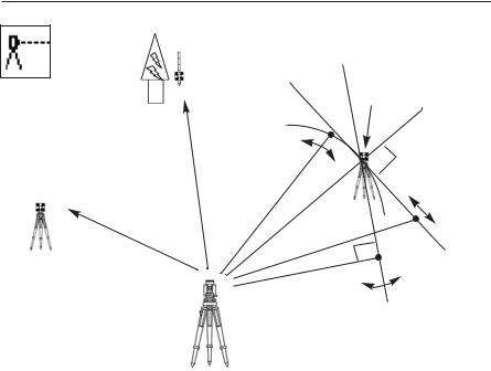
4. MEASURE
3. Rotated
Offset
Reference P.
1. Cylinder
Remote
Backsight P. |
2. Fixed plane |
|
|
Coordinates |
|
|
Azimuth |
|
Station point |
An operator can measure the Foresight point Coordinates from the “Station point Coordinates and Backsight Coordinates” or the “Station point Coordinates and Azimuth”, and can store the Point name and measured Coordinates in the memory. When the Coordinates of the Station point and Backsight point are already stored in the memory, the new Coordinates input can be omitted by calling or searching from the point name LIST. The point name is with in 15 characters and the Coordinates are within 8 in integer and 3 in decimal number. There are two Coordinates types of Rectangular and Polar Coordinates in this [MEASURE].
The Offset at the Target point is possible and the Remote measurement by aiming at any point is possible as well when you select the Rectangular Coordinates.
An operator can perform the [MEASURE] function only when the Telescope is at the “Face left position”.
Select the Target type before performing the [MEASURE].
After measuring rectangular coordinates by [MEASURE] function of PowerTopoLite, it is possible to display Angle and Distance by switching the [F3] key.
When Remote mode is selected, Angle and Distance are also calculated according to the coordinates of the aiming point on real time.
When Offset mode is selected, Angle and Distance are also calculated according to the coordinates where offset value is added.
25
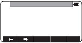
4.1 Station setup [By Rectangular Coordinates]
Press [F2][MEAS] of the PowerTopoLite screen to view the MEASURE METHOD SELECTION screen.
MEASURE METHOD SELECTION
1.RECTANGULAR COORD.
2.POLAR COORD.
Select 1. RECTANGULAR COORD. and press [ENT] to view the STATION POINT SETUP screen.
STATION POINT SETUP
1.PN:
2.X: + 00000000.000m
3.Y: + 00000000.000m
4.Z: + 00000000.000m
5.IH: 0000.000m
SAVE |
LIST |
ACCEPT |
The  /
/  mark is used to scroll up / down. 6. PC is viewed by scrolling down.
STATION POINT SETUP
2.X: + 00000000.000m
3.Y: + 00000000.000m
4.Z: + 00000000.000m
5. |
IH: |
0000.000m |
|
|
|
6. |
PC: |
|
|
|
|
|
|
|
SAVE |
|
LIST |
ACCEPT |
|
|
|
|
|
|
26
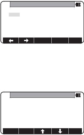
4.1.1 Point name, PN, input
Press [ENT] to view the PN screen.
The [ENT] is used for both accepting the selected choice and opening the input screen of the Coordinates values etc.
PN
1.PN:
2.X: + 00000000.000m
3.Y: + 00000000.000m
4.Z: + 00000000.000m
5.IH: 0000.000m
BS |
CLEAR |
TO 123 |
Input your desired point name by pressing keys, and after all Characters are input, press [ENT].
Four character selection methods are available. (Refer to the “13.3 Input method selection”)
4.1.2 Coordinates, X,Y, Z, IH, and PC input
It goes 2. X coordinate automatically.
X
1.PN: POT1
2.X: + 00000000.000m
3.Y: + 00000000.000m
4.Z: + 00000000.000m
5.IH: 0010.000m
SAVE |
LIST |
ACCEPT |
27
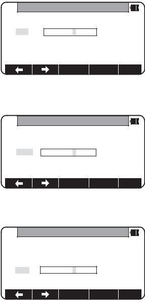
Press [ENT] to view the X coordinate input screen.
Input X, Y and Z coordinates, Instrument height and PC as follows.
Input your desired X coordinate value by pressing each keys.
X
1.PN: POT 1
2.X: + 00000000.000m
3.Y: + 00000000.000m
4.Z: + 00000000.000m
5.IH: 0000.000m
CLEAR
Y coordinate:
Press [ENT] to view the Y coordinate input screen. Input your desired Y coordinate value by pressing keys.
Y
1. PN: |
POT 1 |
2.X: + 00000000.000m
3.Y: + 00000002.000m
4.Z: + 00000000.000m
5.IH: 0000.000m
CLEAR
Z coordinate:
Press [ENT] to view the Z coordinate input screen. Input your desired Z coordinate value by pressing each keys.
Z
1. PN: |
POT 1 |
2.X: + 00000000.000m
3.Y: + 00000000.000m
4.Z: + 00000000.000m
5.IH: 0000.000m
CLEAR
28
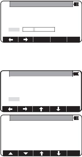
IH value:
Press [ENT] to view the IH, Instrument height, screen. Input your desired IH value by pressing each keys.
IH
1.PN:POT 1
2.X: + 00000000.000m
3.Y: + 00000000.000m
4.Z: + 00000000.000m
5.IH: +0001.500m
CLEAR
PC, Point Code:
Press [ENT] to view and input the PC, Point code, screen.
If PointCode exists, you can easily select them from the list. Then after pressing [ENT], you can edit Point Code data. For using Point Code List, please refer to “4.4 Point Code”.
PC
2.X: + 00000100.000m
3.Y: + 00000200.000m
4.Z: + 00000010.000m
5. IH: |
0010.000m |
6. PC: |
|
CLEAR
POINT CODELIST
1.ABC
2.DEF
3.GHI
4.JKL
5.MNO
29
After pressing [ENT], you can edit Point Code data.
PC
2.X: + 00000100.000m
3.Y: + 00000200.000m
4.Z: + 00000010.000m
5. IH |
0010.000m |
6. PC: |
TEST POI |
BS |
CLEAR |
TO 123 |
Input your desired PC name by pressing keys, and press [ENT] to view next screen.
If “PROCESS TYPE” is selected in “Action method selection”, after input/confirm PC data the inputted POT1 data will automatically be stored in the memory. Then the panel “STATION POINT H.ANGLE SETUP” will be displayed.
But, if “STRUCTURE TYPE” is selected in “Action method selection”, it is necessary to press [ACCEPT] to proceed next panel.
30
 Loading...