


CM6800-32X6
CM6800-32X6 MATRIX SWITCHER
Quick Start Guide

®
Worldwide, there’s so much we can show you.
English
Español
Portuguese
Deutsch
Français
Italiano
Polski
Pycc
K
NN
˘
Step 1. Install the CM6800 and all components of your
system.
Refer to the Quick Start illustrations for an overview of system connections.
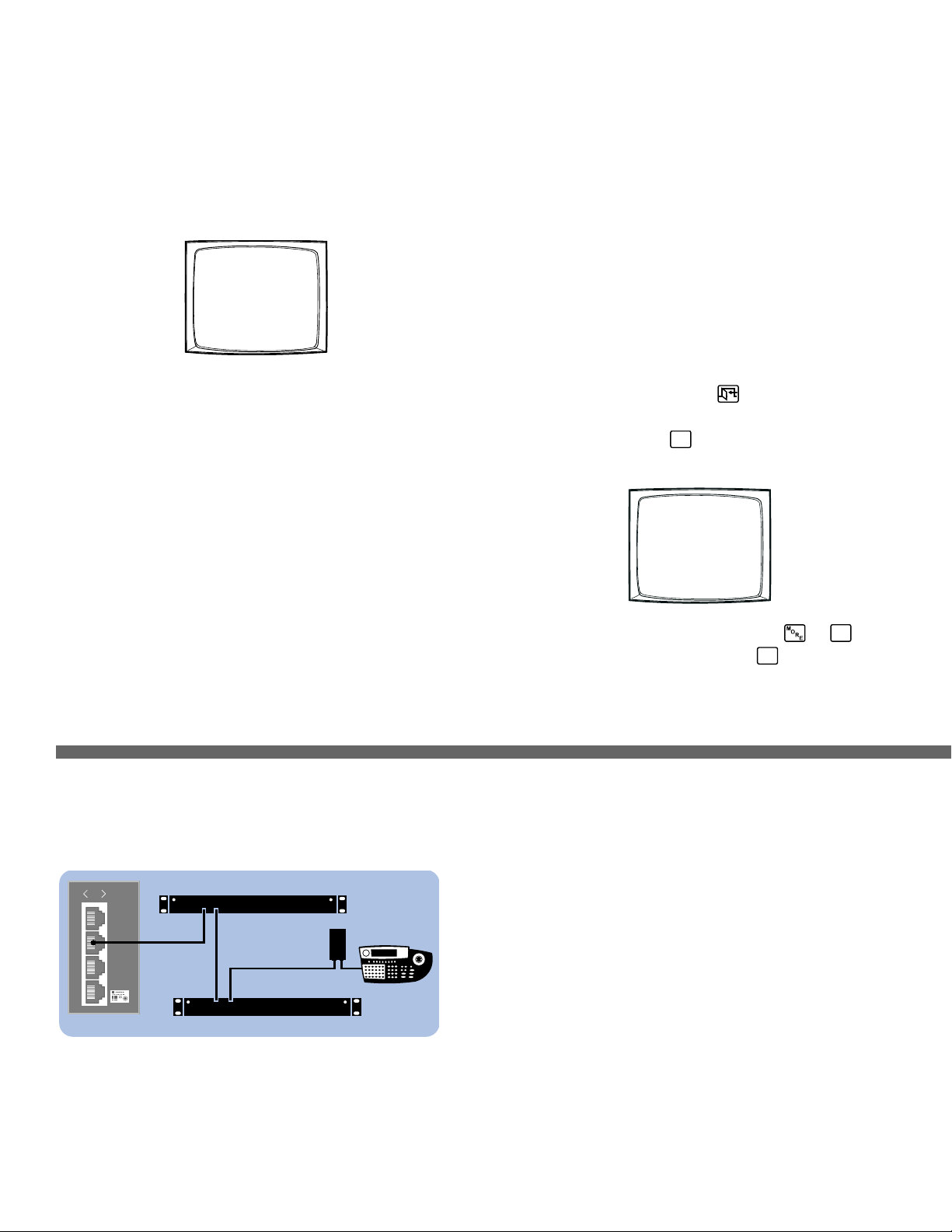
Step 2. Power-up the system.
Video from camera 1 and the Time/Date Stamp appears on all system monitors.
The time stamp advances in one-second increments. WAIT FIVE SECONDS.
Step 3. Initialize keyboards.
From each keyboard select a monitor:
1. Enter the number of the monitor you are viewing.
2. Press the MON key.
If the keyboard LED does not display the monitor number, repeat 1 and 2.
Step 4. Switch cameras and select monitors.
After initializing keyboards you can
• Select Monitors: Enter the monitor number, and then press the MON key.
• Switch Cameras: Press PREV or NEXT, or enter the camera number and
then press the CAM key.
• Control Extended Coaxitron
®
Protocol Receivers: Select a suitable camera
and operate a PTZ function. Other receiver control protocols require
programming changes.
Figure 2. Connecting Multiple M Devices
0001 E CAM 1
0001 01-JAN-01 01:01:01
Any single M device can be connected to Port 3 using a straight cable. If multiple
devices are needed, connect as illustrated below.
CM6800-32X6 INSTALLATION
Step 5. Program your system.
Configure the CM6800 to your specific application in programming mode or
through the CM6800-MGR software. Refer to the CM6800-MGR Quick Start
Guide for instructions on installing the CM6800-MGR.
The CM6800 is shipped from the factory with default programming settings. If the
defaults are acceptable, the CM6800 can be operated without any user
programming. However, you may want to program the following settings:
• Time and date
• Camera titles
• PTZ control via hard-wire data connections
• Communication ports – To connect remote keyboards to COM 4 (the
alternate connection shown in Figure 1), change the Port 4 settings.
Access programming mode:
If you have not already done so, select the monitor. If the Camera menu appears
on the KBD960/KBR960 LCD display, press
to exit.
1. Press the PGM key (or select
PGM
on the KBD960/KBR960). The Password
screen appears.
NOTE: On the KBD960/KBR960 you must first select and
DEF
. Then
enter the Define PIN (Default: 1234), and select
MENU
.
2. Enter the default password: 2899100. The Main Menu appears.
PELCO VIDEO SWITCHER
MODEL CM6800
PASSWORD TO MAIN MENU
**********
SCRATCHPAD SEQUENCE
MACRO STATUS VIEW
RETURN
Device Settings:
Each M device connected to the CM6800 must have a unique local address. For
detailed instructions on device settings, refer to the appropriate device manual.
ALM2064 and REL2064 DIP Switch Settings:
(Note: DIP switches are located behind the front panel cover.)
1. Set SW2, DIP switches 1-8 to the appropriate local address positions.
2. Cycle power.
KBD960 Settings:
1. Set DIP switch 2 to the ON position.
2. Enter Setup Mode.
3. Select the baud rate and set the local address.
4. Return DIP switch 2 to the OFF position.
5. Press the EXIT icon on the keyboard LCD screen.
010101
1
2
3
4
010101
2
3
4
5
KBD960
USE KBD960
COM 1
REL2064
ALM2064
RS-485
OUT IN
OUT IN
COM 3 DEFAULTS:
M, RS-485, 19200 baud, no parity, 8 data bits, 1 stop bit
English
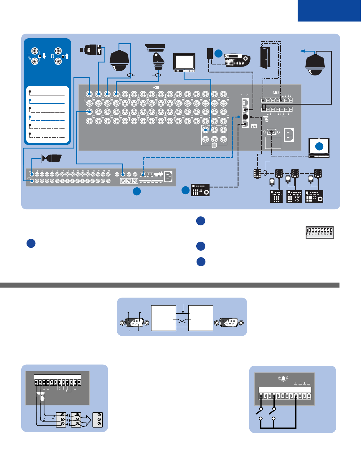
Figure 1. CM6800-32X6 Connections
Figure 3. PC Connection
Figure 4. PTZ Control Connections
Figure 5. Alarm Connections
CM6800 CONFIGURATION
Identify each camera’s receiver control type as PTZ-A.
Configure PTZ-A port for communication type (P or D).
CAMERA/RECEIVER CONFIGURATION
Refer to the appropriate camera installation manual for
configuration and addressing scheme settings.
PTZ-A DEFAULTS:
PTZ-P, RS-422, 4800 baud, no parity, 8 data bits, 1 stop bit
Maximum cable distance 4,000 feet (1,219 m)
(For a ”star“ configuration use a CM9760-CDU-T.)
Port 5 powers 1 keyboard.
KBD300A default (address 0) DIP switch settings:
DIP switches 1-8 off (all up)
Refer to Figure 3 for PC connections. Also refer to CM6800-MGR
Quick Start Guide for PC setup.
Refer to Figure 2 for M device settings.
Each CM6800-32X6 port is configured for a specific type of device or usage. Use
ports as shown, or refer to the CM6800-32X6 Installation/Operation Manual for
additional options.
Genex
®
must be in slave mode. Configure each Genex
®
camera
(through the CM6800 Camera programming screen):
CONTROL: MUX
PORT ADDRESS: must match the Genex
®
”Unit ID“
NULL MODEM CABLE
CM6800 COM 1
DB9 PINOUTS
PIN 2 = RX IN
PIN 3 = TX OUT
PIN 5 = GND
PIN 5
PIN 1
PIN 6
PIN 9
PC COM 1
DB9 PINOUTS
PIN 2 = RX IN
PIN 3 = TX OUT
PIN 5 = GND
CONTROL
RECEIVER 2RECEIVER 1
R+
R-
GND
R+
R-
GND
RS-422
RECEIVER 16
R+
R-
GND
T
+
T
-
R
+
R
-
F
2
1234567812345678
ALARM DEFAULT: N.O.
(NORMALLY OPEN);
CLOSURE TRIGGERS
ALARM
010101
2
3
4
5
161514131211109
8
7654321
654
3231302928272625
24
23222120191817
321
120/230~
50/60 HZ
25 WATTS
12345678
CONTROL
T
+
T
-
R
+
R
-
HZ
75
1
CC3700H-2
VCR
AUX
MAIN
SPOT
SVHS
OUT IN
SVHS
IN COM OUT
NNH
OC
C
S
ALARMS
12345678 91011 1415161213
110-240V50/60 Hz
CAMCLOSURE
010101
2
3
4
5
161514131211109
8
7654321
654
3231302928272625
24
23222120191817
321
120/230~
50/60 HZ
25 WATTS
12345678
CONTROL
T
+
T
-
R
+
R
-
HZ
75
1
VCR
AUX
MAIN
SPOT
SVHS
OUT IN
SVHS
IN COM OUT
NNH
OC
C
S
ALARMS
12345678 91011 1415161213
110-240V50/60 Hz
SPECTRA
KBD300A
COM 1 DEFAULTS:
MGR, RS-232, 56000 BAUD,
NO PARITY, 8 DATA BITS,
1 STOP BIT
KBDKIT (-X)
KBD960
CM9505UPS
WALL
BLOCK
12 V
TRANSFORMER
ALARM CONTACT
VIDEO TO
SWITCHER
GENEX MULTIPLEXER
PC
4-CONDUCTOR, SHIELDED, 24-GAUGE, SUCH AS
BELDEN 9843
1
HZ
75
1
TERMINATED LOOPING
VIDEO INPUT TERMINATING
SWITCH DETAIL
B
D
A
C
COM 4 DEFAULTS:
MUX, RS-485, 9600 BAUD,
ODD PARITY, 8 DATA BITS,
1 STOP BIT
COM 4 ALTERNATE OPTION:
KBD300, RS-485, 9600 BAUD,
ODD PARITY, 8 DATA BITS,
1 STOP BIT
LOOPING CONNECTIONS MUST
BE TERMINATED WITH 75 OHMs
AT THE LAST DEVICE
RS-422
VIDEO/COAX
STRAIGHT RS-485
REVERSE RS-485
RS-232 NULL MODEM
DRY CONTACT
PTZ CONTROL
SHIELDED
TWISTED
PAIR
COAXITRON
HZ
75
CM6800-32X6
ESPRIT
F
2
MONITOR
OR
COM 5 DEFAULTS:
KBD300, RS-485
9600 BAUD, ODD PARITY,
8 DATA BITS, 1 STOP BIT
25 FT
CABLE
KBD100 KBD200A KBD300A
A
B
C
D
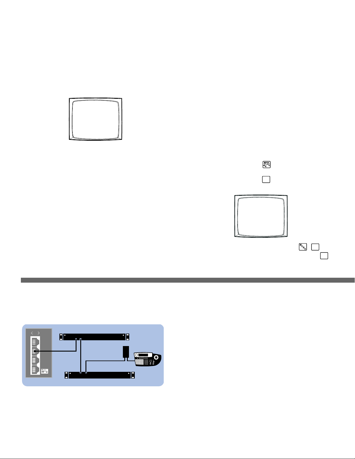
Figura 2. Conexión de Múltiple Dispositivos
0001 E CAM 1
0001 01-JAN-01 01:01:01
SECUENCIADOR DE VÍDEO PELCO
MODELO CM6800
CONTRASEÑA PARA MENÚ PRINCIPAL
**********
SECUENCIA DE TRABAJO
ESTADO MACRO VISTA
REGRESAR
010101
1
2
3
4
010101
2
3
4
5
RS-485
KBD960
USE KBD960
COM 1
REL2064
ALM2064
OUT IN
OUT IN
INSTALACIÓN DEL CM6800-32X6
Paso 1. Instalar el CM6800 y todos los componentes de su
sistema.
Consulte las ilustraciones de Inicio Rápido para tener una idea general de las
conexiones del sistema.
Paso 2. Energizar el sistema.
El video de la cámara 1 y la etiqueta Hora /Fecha aparecerán en todos los
monitores del sistema.
La etiqueta de hora avanzará en incrementos de un segundo. ESPERE CINCO
SEGUNDOS antes de continuar.
Paso 3. Inicializar los teclados.
En cada teclado seleccione un monitor:
1. Introduzca el número del monitor que está viendo.
2. Presione la tecla MON.
Si el teclado LED no muestra el número de monitor, repita los pasos 1 y 2.
Paso 4. Cambiar cámaras y seleccionar monitores.
Después de inicializar los teclados, puede
• Seleccionar monitores: Introduzca el número de monitor y después presione
la tecla MON.
• Cambiar cámaras: Presione PREV o NEXT, o introduzca el número de
cámara, y después presione la tecla CAM.
• Controlar receptores de protocolo Coaxitron
®
extendido: Seleccione una
cámara adecuada y active una función PTZ. Otros protocolos de control de
receptor requieren cambios de programación..
Paso 5. Programar su sistema.
Configure el CM6800 según su aplicación específica en el modo Programación o
mediante el software CM6800-MGR. Consulte la Guía para Inicio Rápido de
Operación de CM6800-MGR para obtener instrucciones para instalar el
CM6800-MGR.
El CM6800 se envía de fábrica con una configuración de programación por
defecto. Si ésta es aceptable, el CM6800 puede funcionar sin que el usuario
deba hacer ninguna programación. Pero es posible que programar la
configuración de las siguientes funciones:
• Hora y fecha
• Títulos de cámara
• Control PTZ vía cable de conexión de datos
• Puertos de comunicación: Para conectar teclados remotos al COM 4 (la
conexión alternativa que se muestra en la Figura 1), cambie las
configuraciones del Puerto 4.
Acceso al modo Programación:
Si todavía no lo hizo, seleccione el monitor. Si aparece el menú Cámara en la
pantalla KBD960/KBR960 LCD, presione para salir.
1. Presione la tecla PGM (o seleccione
PGM
en el KBD960/KBR960). Aparece
la pantalla Contraseña.
NOTA: En el KBD960/KBR960 primero debe seleccionar
y
DEF
.
Después introduzca el PIN definido (por defecto: 1234), y seleccione
MENU
.
2. Introduzca la contraseña por defecto: 2899100. Aparecerá el Menú Principal.
Cualquier dispositivo M único se puede conectar al Puerto 3 usando un cable directo.
Si se necesitan múltiples dispositivos, conéctelos de la siguiente manera.
CONFIGURACIÓN POR DEFECTO DE COM 3:
M, RS-485, 19200 baudios, sin paridad, 8 bits de datos, 1 bit de parada
Configuración de dispositivos:
Cada dispositivo M conectado al CM6800 debe tener una dirección local única. Para
obtener instrucciones detalladas sobre la configuración de dispositivos, consulte el
manual del dispositivo adecuado.
Configuración de interruptores DIP ALM2064 y REL2064:
(Nota: Los interruptores DIP están ubicados detrás de la cubierta del panel frontal)
1. Coloque los interruptores DIP 1-8 SW2 en las posiciones de dirección local
adecuadas.
2. Active la alimentación eléctrica.
Configuración de KBD960:
1. Coloque el interruptor DIP 2 en posición ON.
2. Ingrese al modo Configuración.
3. Seleccione los baudios y configure la dirección local.
4. Vuelva a colocar el interruptor DIP 2 en posición OFF.
5. Presione el icono EXIT en el teclado de la ventana LCD.
 Loading...