


I N S T A L L A T I O N
DX8100 Series
Digital Video Recorder
C2629M-A (6/07)

Contents
Before You Begin . . . . . . . . . . . . . . . . . . . . . . . . . . . . . . . . . . . . . . . . . . . . . . . . . . . . . . . . . . . . . . . . . . . . . . . . . . . . . . . . . . . . . . . . . . . . . . . . . . . . . 8
Additional Warnings . . . . . . . . . . . . . . . . . . . . . . . . . . . . . . . . . . . . . . . . . . . . . . . . . . . . . . . . . . . . . . . . . . . . . . . . . . . . . . . . . . . . . . . . . . . . . . . . . . . 9
Regulatory Notices . . . . . . . . . . . . . . . . . . . . . . . . . . . . . . . . . . . . . . . . . . . . . . . . . . . . . . . . . . . . . . . . . . . . . . . . . . . . . . . . . . . . . . . . . . . . . . . . . . . 10
Video Quality . . . . . . . . . . . . . . . . . . . . . . . . . . . . . . . . . . . . . . . . . . . . . . . . . . . . . . . . . . . . . . . . . . . . . . . . . . . . . . . . . . . . . . . . . . . . . . . . . . . . . . . . 10
Description . . . . . . . . . . . . . . . . . . . . . . . . . . . . . . . . . . . . . . . . . . . . . . . . . . . . . . . . . . . . . . . . . . . . . . . . . . . . . . . . . . . . . . . . . . . . . . . . . . . . . . . . . 11
What is A DVR? . . . . . . . . . . . . . . . . . . . . . . . . . . . . . . . . . . . . . . . . . . . . . . . . . . . . . . . . . . . . . . . . . . . . . . . . . . . . . . . . . . . . . . . . . . . . . . . . . 11
Features . . . . . . . . . . . . . . . . . . . . . . . . . . . . . . . . . . . . . . . . . . . . . . . . . . . . . . . . . . . . . . . . . . . . . . . . . . . . . . . . . . . . . . . . . . . . . . . . . . . . . . . 12
New Product Features . . . . . . . . . . . . . . . . . . . . . . . . . . . . . . . . . . . . . . . . . . . . . . . . . . . . . . . . . . . . . . . . . . . . . . . . . . . . . . . . . . . . . . . 12
Additional Features . . . . . . . . . . . . . . . . . . . . . . . . . . . . . . . . . . . . . . . . . . . . . . . . . . . . . . . . . . . . . . . . . . . . . . . . . . . . . . . . . . . . . . . . . . 12
Models . . . . . . . . . . . . . . . . . . . . . . . . . . . . . . . . . . . . . . . . . . . . . . . . . . . . . . . . . . . . . . . . . . . . . . . . . . . . . . . . . . . . . . . . . . . . . . . . . . . . . . . . 13
Optional Accessories . . . . . . . . . . . . . . . . . . . . . . . . . . . . . . . . . . . . . . . . . . . . . . . . . . . . . . . . . . . . . . . . . . . . . . . . . . . . . . . . . . . . . . . . . . . . . 14
Parts List . . . . . . . . . . . . . . . . . . . . . . . . . . . . . . . . . . . . . . . . . . . . . . . . . . . . . . . . . . . . . . . . . . . . . . . . . . . . . . . . . . . . . . . . . . . . . . . . . . . . . . . . . . . 15
Application Examples . . . . . . . . . . . . . . . . . . . . . . . . . . . . . . . . . . . . . . . . . . . . . . . . . . . . . . . . . . . . . . . . . . . . . . . . . . . . . . . . . . . . . . . . . . . . . . . . . 16
Equipment Rack Mounting . . . . . . . . . . . . . . . . . . . . . . . . . . . . . . . . . . . . . . . . . . . . . . . . . . . . . . . . . . . . . . . . . . . . . . . . . . . . . . . . . . . . . . . . . . . . . 18
Back Panel Layout . . . . . . . . . . . . . . . . . . . . . . . . . . . . . . . . . . . . . . . . . . . . . . . . . . . . . . . . . . . . . . . . . . . . . . . . . . . . . . . . . . . . . . . . . . . . . . . . . . . . 20
Hardware Setup . . . . . . . . . . . . . . . . . . . . . . . . . . . . . . . . . . . . . . . . . . . . . . . . . . . . . . . . . . . . . . . . . . . . . . . . . . . . . . . . . . . . . . . . . . . . . . . . . . . . . 21
Basic Connections . . . . . . . . . . . . . . . . . . . . . . . . . . . . . . . . . . . . . . . . . . . . . . . . . . . . . . . . . . . . . . . . . . . . . . . . . . . . . . . . . . . . . . . . . . . . . . . 21
Network Setup . . . . . . . . . . . . . . . . . . . . . . . . . . . . . . . . . . . . . . . . . . . . . . . . . . . . . . . . . . . . . . . . . . . . . . . . . . . . . . . . . . . . . . . . . . . . . . . . . . 22
RS-422/RS-485 Communication Port Setup . . . . . . . . . . . . . . . . . . . . . . . . . . . . . . . . . . . . . . . . . . . . . . . . . . . . . . . . . . . . . . . . . . . . . . . . . . . 22
Alarm Input Installation . . . . . . . . . . . . . . . . . . . . . . . . . . . . . . . . . . . . . . . . . . . . . . . . . . . . . . . . . . . . . . . . . . . . . . . . . . . . . . . . . . . . . . . . . . . 24
Relay Output Installation . . . . . . . . . . . . . . . . . . . . . . . . . . . . . . . . . . . . . . . . . . . . . . . . . . . . . . . . . . . . . . . . . . . . . . . . . . . . . . . . . . . . . . . . . . 25
Software Setup . . . . . . . . . . . . . . . . . . . . . . . . . . . . . . . . . . . . . . . . . . . . . . . . . . . . . . . . . . . . . . . . . . . . . . . . . . . . . . . . . . . . . . . . . . . . . . . . . . . . . . 26 Starting the Unit . . . . . . . . . . . . . . . . . . . . . . . . . . . . . . . . . . . . . . . . . . . . . . . . . . . . . . . . . . . . . . . . . . . . . . . . . . . . . . . . . . . . . . . . . . . . . . . . 26 Logging in for the First Time . . . . . . . . . . . . . . . . . . . . . . . . . . . . . . . . . . . . . . . . . . . . . . . . . . . . . . . . . . . . . . . . . . . . . . . . . . . . . . . . . . . . . . . 26 Shutting Down . . . . . . . . . . . . . . . . . . . . . . . . . . . . . . . . . . . . . . . . . . . . . . . . . . . . . . . . . . . . . . . . . . . . . . . . . . . . . . . . . . . . . . . . . . . . . . . . . . 27 Exiting to Windows Operating System . . . . . . . . . . . . . . . . . . . . . . . . . . . . . . . . . . . . . . . . . . . . . . . . . . . . . . . . . . . . . . . . . . . . . . . . . . . . . . . 27 Setting the System Language . . . . . . . . . . . . . . . . . . . . . . . . . . . . . . . . . . . . . . . . . . . . . . . . . . . . . . . . . . . . . . . . . . . . . . . . . . . . . . . . . . . . . . 28
Configuring the Regional Setting in the Windows Operating System . . . . . . . . . . . . . . . . . . . . . . . . . . . . . . . . . . . . . . . . . . . . . . . . . . . 28 Configuring the Language Setting of the DX8100 . . . . . . . . . . . . . . . . . . . . . . . . . . . . . . . . . . . . . . . . . . . . . . . . . . . . . . . . . . . . . . . . . . 31 Setting the System Time . . . . . . . . . . . . . . . . . . . . . . . . . . . . . . . . . . . . . . . . . . . . . . . . . . . . . . . . . . . . . . . . . . . . . . . . . . . . . . . . . . . . . . . . . . 32 Enabling and Using Ctrl+Alt+Del . . . . . . . . . . . . . . . . . . . . . . . . . . . . . . . . . . . . . . . . . . . . . . . . . . . . . . . . . . . . . . . . . . . . . . . . . . . . . . . . . . . . 33 Using Ctrl+Alt+Del . . . . . . . . . . . . . . . . . . . . . . . . . . . . . . . . . . . . . . . . . . . . . . . . . . . . . . . . . . . . . . . . . . . . . . . . . . . . . . . . . . . . . . . . . . 33 Network Software Configuration . . . . . . . . . . . . . . . . . . . . . . . . . . . . . . . . . . . . . . . . . . . . . . . . . . . . . . . . . . . . . . . . . . . . . . . . . . . . . . . . . . . 33 DHCP Setup . . . . . . . . . . . . . . . . . . . . . . . . . . . . . . . . . . . . . . . . . . . . . . . . . . . . . . . . . . . . . . . . . . . . . . . . . . . . . . . . . . . . . . . . . . . . . . . . 35 Static IP Setup . . . . . . . . . . . . . . . . . . . . . . . . . . . . . . . . . . . . . . . . . . . . . . . . . . . . . . . . . . . . . . . . . . . . . . . . . . . . . . . . . . . . . . . . . . . . . 35 TCP/IP Port and Bandwidth Throttle Setup . . . . . . . . . . . . . . . . . . . . . . . . . . . . . . . . . . . . . . . . . . . . . . . . . . . . . . . . . . . . . . . . . . . . . . . 36 Accessing Network Information . . . . . . . . . . . . . . . . . . . . . . . . . . . . . . . . . . . . . . . . . . . . . . . . . . . . . . . . . . . . . . . . . . . . . . . . . . . . . . . . 37 DNS/WINS Setup . . . . . . . . . . . . . . . . . . . . . . . . . . . . . . . . . . . . . . . . . . . . . . . . . . . . . . . . . . . . . . . . . . . . . . . . . . . . . . . . . . . . . . . . . . . 37 RS-422/RS-485 Communication Port Software Configuration . . . . . . . . . . . . . . . . . . . . . . . . . . . . . . . . . . . . . . . . . . . . . . . . . . . . . . . . . . . . . 38 Client Software Setup . . . . . . . . . . . . . . . . . . . . . . . . . . . . . . . . . . . . . . . . . . . . . . . . . . . . . . . . . . . . . . . . . . . . . . . . . . . . . . . . . . . . . . . . . . . . 39 Recommended System Requirements . . . . . . . . . . . . . . . . . . . . . . . . . . . . . . . . . . . . . . . . . . . . . . . . . . . . . . . . . . . . . . . . . . . . . . . . . . . 39 Installing the PC Client Application . . . . . . . . . . . . . . . . . . . . . . . . . . . . . . . . . . . . . . . . . . . . . . . . . . . . . . . . . . . . . . . . . . . . . . . . . . . . . 40 Enabling IPSec Security Services . . . . . . . . . . . . . . . . . . . . . . . . . . . . . . . . . . . . . . . . . . . . . . . . . . . . . . . . . . . . . . . . . . . . . . . . . . . . . . . 43 Disabling IPSec Security Services . . . . . . . . . . . . . . . . . . . . . . . . . . . . . . . . . . . . . . . . . . . . . . . . . . . . . . . . . . . . . . . . . . . . . . . . . . . . . . 43 Installing the Client Emergency Agent Application . . . . . . . . . . . . . . . . . . . . . . . . . . . . . . . . . . . . . . . . . . . . . . . . . . . . . . . . . . . . . . . . . 43 Installing the DX8100 Viewer . . . . . . . . . . . . . . . . . . . . . . . . . . . . . . . . . . . . . . . . . . . . . . . . . . . . . . . . . . . . . . . . . . . . . . . . . . . . . . . . . . 47 Installing the DX8100 Web Client . . . . . . . . . . . . . . . . . . . . . . . . . . . . . . . . . . . . . . . . . . . . . . . . . . . . . . . . . . . . . . . . . . . . . . . . . . . . . . 49 Recommended System Requirements for Mobile (PDA) Client . . . . . . . . . . . . . . . . . . . . . . . . . . . . . . . . . . . . . . . . . . . . . . . . . . . . . . . . 51 Installing the Mobile (PDA) Client application . . . . . . . . . . . . . . . . . . . . . . . . . . . . . . . . . . . . . . . . . . . . . . . . . . . . . . . . . . . . . . . . . . . . . 51
C2629M-A (6/07) |
3 |
Accessing DX8100 Electronic Documentation . . . . . . . . . . . . . . . . . . . . . . . . . . . . . . . . . . . . . . . . . . . . . . . . . . . . . . . . . . . . . . . . . . . . . . . . . . . . . . |
54 |
Appendix A: Printer Setup . . . . . . . . . . . . . . . . . . . . . . . . . . . . . . . . . . . . . . . . . . . . . . . . . . . . . . . . . . . . . . . . . . . . . . . . . . . . . . . . . . . . . . . . . . . . . |
56 |
Printer Hardware Setup . . . . . . . . . . . . . . . . . . . . . . . . . . . . . . . . . . . . . . . . . . . . . . . . . . . . . . . . . . . . . . . . . . . . . . . . . . . . . . . . . . . . . . . . . . . |
56 |
Printer Software Setup . . . . . . . . . . . . . . . . . . . . . . . . . . . . . . . . . . . . . . . . . . . . . . . . . . . . . . . . . . . . . . . . . . . . . . . . . . . . . . . . . . . . . . . . . . . |
57 |
Setting Up a Local Plug-and-Play Printer . . . . . . . . . . . . . . . . . . . . . . . . . . . . . . . . . . . . . . . . . . . . . . . . . . . . . . . . . . . . . . . . . . . . . . . . . |
57 |
Setting Up a Local Printer that is Not Plug-and-Play . . . . . . . . . . . . . . . . . . . . . . . . . . . . . . . . . . . . . . . . . . . . . . . . . . . . . . . . . . . . . . . . |
60 |
Setting Up a Network Printer . . . . . . . . . . . . . . . . . . . . . . . . . . . . . . . . . . . . . . . . . . . . . . . . . . . . . . . . . . . . . . . . . . . . . . . . . . . . . . . . . . |
64 |
Appendix B: Connecting the Optional DX8108/DX8116-MUX Card . . . . . . . . . . . . . . . . . . . . . . . . . . . . . . . . . . . . . . . . . . . . . . . . . . . . . . . . . . . . . . 67
Appendix C: Connecting Audio Devices . . . . . . . . . . . . . . . . . . . . . . . . . . . . . . . . . . . . . . . . . . . . . . . . . . . . . . . . . . . . . . . . . . . . . . . . . . . . . . . . . . . 68 Setting Up Standard Audio Inputs . . . . . . . . . . . . . . . . . . . . . . . . . . . . . . . . . . . . . . . . . . . . . . . . . . . . . . . . . . . . . . . . . . . . . . . . . . . . . . . . . . . 68 Setting Up Optional Audio Connections . . . . . . . . . . . . . . . . . . . . . . . . . . . . . . . . . . . . . . . . . . . . . . . . . . . . . . . . . . . . . . . . . . . . . . . . . . . . . . 68 Setting Up Audio Output . . . . . . . . . . . . . . . . . . . . . . . . . . . . . . . . . . . . . . . . . . . . . . . . . . . . . . . . . . . . . . . . . . . . . . . . . . . . . . . . . . . . . . . . . . 70
Appendix D: Connecting an Uninterruptible Power Supply (UPS) . . . . . . . . . . . . . . . . . . . . . . . . . . . . . . . . . . . . . . . . . . . . . . . . . . . . . . . . . . . . . . . 71 UPS to DVR Communication and Power Connections . . . . . . . . . . . . . . . . . . . . . . . . . . . . . . . . . . . . . . . . . . . . . . . . . . . . . . . . . . . . . . . . . . . . 71 Software Setup for a USB Connected UPS Device . . . . . . . . . . . . . . . . . . . . . . . . . . . . . . . . . . . . . . . . . . . . . . . . . . . . . . . . . . . . . . . . . . . . . . 72
Appendix E: External Storage Expansion Using DX9200HDDI . . . . . . . . . . . . . . . . . . . . . . . . . . . . . . . . . . . . . . . . . . . . . . . . . . . . . . . . . . . . . . . . . . |
74 |
Appendix F: Connecting a KBD300A Keyboard . . . . . . . . . . . . . . . . . . . . . . . . . . . . . . . . . . . . . . . . . . . . . . . . . . . . . . . . . . . . . . . . . . . . . . . . . . . . . |
75 |
Required Items . . . . . . . . . . . . . . . . . . . . . . . . . . . . . . . . . . . . . . . . . . . . . . . . . . . . . . . . . . . . . . . . . . . . . . . . . . . . . . . . . . . . . . . . . . . . . . . . . . |
76 |
Installing KBD300A Hardware . . . . . . . . . . . . . . . . . . . . . . . . . . . . . . . . . . . . . . . . . . . . . . . . . . . . . . . . . . . . . . . . . . . . . . . . . . . . . . . . . . . . . . |
76 |
Selecting the KBD300A Operational Mode . . . . . . . . . . . . . . . . . . . . . . . . . . . . . . . . . . . . . . . . . . . . . . . . . . . . . . . . . . . . . . . . . . . . . . . |
77 |
Appendix G: Connecting ATM/POS Devices . . . . . . . . . . . . . . . . . . . . . . . . . . . . . . . . . . . . . . . . . . . . . . . . . . . . . . . . . . . . . . . . . . . . . . . . . . . . . . . |
78 |
ATM/POS Configurations . . . . . . . . . . . . . . . . . . . . . . . . . . . . . . . . . . . . . . . . . . . . . . . . . . . . . . . . . . . . . . . . . . . . . . . . . . . . . . . . . . . . . . . . . |
78 |
Connecting ATM/POS Hardware . . . . . . . . . . . . . . . . . . . . . . . . . . . . . . . . . . . . . . . . . . . . . . . . . . . . . . . . . . . . . . . . . . . . . . . . . . . . . . . . . . . . |
79 |
Using the VSI-PRO Triport Cable . . . . . . . . . . . . . . . . . . . . . . . . . . . . . . . . . . . . . . . . . . . . . . . . . . . . . . . . . . . . . . . . . . . . . . . . . . . . . . . |
79 |
Setting Up a RS-232 ATM/POS Device Configuration . . . . . . . . . . . . . . . . . . . . . . . . . . . . . . . . . . . . . . . . . . . . . . . . . . . . . . . . . . . . . . . |
80 |
Setting Up a RS-422 ATM/POS Device Configuration . . . . . . . . . . . . . . . . . . . . . . . . . . . . . . . . . . . . . . . . . . . . . . . . . . . . . . . . . . . . . . . |
81 |
Configuring DX8100 ATM/POS Communication Options . . . . . . . . . . . . . . . . . . . . . . . . . . . . . . . . . . . . . . . . . . . . . . . . . . . . . . . . . . . . . . . . . |
84 |
Specifications . . . . . . . . . . . . . . . . . . . . . . . . . . . . . . . . . . . . . . . . . . . . . . . . . . . . . . . . . . . . . . . . . . . . . . . . . . . . . . . . . . . . . . . . . . . . . . . . . . . . . . . |
90 |
4 |
C2629M-A (6/07) |

List of Illustrations |
|
|
1 |
System with Single DX8100 . . . . . . . . . . . . . . . . . . . . . . . . . . . . . . . . . . . . . . . . . . . . . . . . . . . . . . . . . . . . . . . . . . . . . . . . . . . . . . . . . . . |
16 |
2 |
System with Multiple DX8100s . . . . . . . . . . . . . . . . . . . . . . . . . . . . . . . . . . . . . . . . . . . . . . . . . . . . . . . . . . . . . . . . . . . . . . . . . . . . . . . . . |
16 |
3 |
System with Multiple DX8100s and Multiple Clients . . . . . . . . . . . . . . . . . . . . . . . . . . . . . . . . . . . . . . . . . . . . . . . . . . . . . . . . . . . . . . . . |
16 |
4 |
Network with DX8000, Third-Party Domes, ATM/POS, Using KDB300A Keyboard . . . . . . . . . . . . . . . . . . . . . . . . . . . . . . . . . . . . . . . . |
17 |
5 |
Remove Left and Right Side Plates . . . . . . . . . . . . . . . . . . . . . . . . . . . . . . . . . . . . . . . . . . . . . . . . . . . . . . . . . . . . . . . . . . . . . . . . . . . . . . |
18 |
6 |
Attaching Rack Ears and Handles . . . . . . . . . . . . . . . . . . . . . . . . . . . . . . . . . . . . . . . . . . . . . . . . . . . . . . . . . . . . . . . . . . . . . . . . . . . . . . . |
18 |
7 |
Rack Mount Installation . . . . . . . . . . . . . . . . . . . . . . . . . . . . . . . . . . . . . . . . . . . . . . . . . . . . . . . . . . . . . . . . . . . . . . . . . . . . . . . . . . . . . . . |
19 |
8 |
Back Panel Layout . . . . . . . . . . . . . . . . . . . . . . . . . . . . . . . . . . . . . . . . . . . . . . . . . . . . . . . . . . . . . . . . . . . . . . . . . . . . . . . . . . . . . . . . . . . |
20 |
9 |
Basic Connections . . . . . . . . . . . . . . . . . . . . . . . . . . . . . . . . . . . . . . . . . . . . . . . . . . . . . . . . . . . . . . . . . . . . . . . . . . . . . . . . . . . . . . . . . . . |
21 |
10 |
LAN/WAN Cable Connection . . . . . . . . . . . . . . . . . . . . . . . . . . . . . . . . . . . . . . . . . . . . . . . . . . . . . . . . . . . . . . . . . . . . . . . . . . . . . . . . . . . |
22 |
11 |
RS-422/RS-485 Configuration Example 1 . . . . . . . . . . . . . . . . . . . . . . . . . . . . . . . . . . . . . . . . . . . . . . . . . . . . . . . . . . . . . . . . . . . . . . . . . |
23 |
12 |
RS-422/RS-485 Configuration Example 2 . . . . . . . . . . . . . . . . . . . . . . . . . . . . . . . . . . . . . . . . . . . . . . . . . . . . . . . . . . . . . . . . . . . . . . . . . |
23 |
13 |
Cable Wiring Schemes . . . . . . . . . . . . . . . . . . . . . . . . . . . . . . . . . . . . . . . . . . . . . . . . . . . . . . . . . . . . . . . . . . . . . . . . . . . . . . . . . . . . . . . |
24 |
14 |
Alarm Terminal Installation . . . . . . . . . . . . . . . . . . . . . . . . . . . . . . . . . . . . . . . . . . . . . . . . . . . . . . . . . . . . . . . . . . . . . . . . . . . . . . . . . . . . |
24 |
15 |
Relay Terminal Installation . . . . . . . . . . . . . . . . . . . . . . . . . . . . . . . . . . . . . . . . . . . . . . . . . . . . . . . . . . . . . . . . . . . . . . . . . . . . . . . . . . . . |
25 |
16 |
Front Panel and Power Switch . . . . . . . . . . . . . . . . . . . . . . . . . . . . . . . . . . . . . . . . . . . . . . . . . . . . . . . . . . . . . . . . . . . . . . . . . . . . . . . . . . |
26 |
17 |
User Log-in Dialog Box . . . . . . . . . . . . . . . . . . . . . . . . . . . . . . . . . . . . . . . . . . . . . . . . . . . . . . . . . . . . . . . . . . . . . . . . . . . . . . . . . . . . . . . |
26 |
18 |
Set Admin Password Dialog Box . . . . . . . . . . . . . . . . . . . . . . . . . . . . . . . . . . . . . . . . . . . . . . . . . . . . . . . . . . . . . . . . . . . . . . . . . . . . . . . . |
27 |
19 |
Shut Down Dialog Box . . . . . . . . . . . . . . . . . . . . . . . . . . . . . . . . . . . . . . . . . . . . . . . . . . . . . . . . . . . . . . . . . . . . . . . . . . . . . . . . . . . . . . . . |
27 |
20 |
Shut Down Dialog Box . . . . . . . . . . . . . . . . . . . . . . . . . . . . . . . . . . . . . . . . . . . . . . . . . . . . . . . . . . . . . . . . . . . . . . . . . . . . . . . . . . . . . . . . |
28 |
21 |
Control Panel with Regional Options Selected . . . . . . . . . . . . . . . . . . . . . . . . . . . . . . . . . . . . . . . . . . . . . . . . . . . . . . . . . . . . . . . . . . . . . |
28 |
22 |
Regional Options Dialog Box . . . . . . . . . . . . . . . . . . . . . . . . . . . . . . . . . . . . . . . . . . . . . . . . . . . . . . . . . . . . . . . . . . . . . . . . . . . . . . . . . . . |
29 |
23 |
Select System Locale Dialog Box . . . . . . . . . . . . . . . . . . . . . . . . . . . . . . . . . . . . . . . . . . . . . . . . . . . . . . . . . . . . . . . . . . . . . . . . . . . . . . . |
29 |
24 |
Regional Options Dialog Box . . . . . . . . . . . . . . . . . . . . . . . . . . . . . . . . . . . . . . . . . . . . . . . . . . . . . . . . . . . . . . . . . . . . . . . . . . . . . . . . . . . |
30 |
25 |
General Dialog Box . . . . . . . . . . . . . . . . . . . . . . . . . . . . . . . . . . . . . . . . . . . . . . . . . . . . . . . . . . . . . . . . . . . . . . . . . . . . . . . . . . . . . . . . . . |
30 |
26 |
Change Regional Options Dialog Box . . . . . . . . . . . . . . . . . . . . . . . . . . . . . . . . . . . . . . . . . . . . . . . . . . . . . . . . . . . . . . . . . . . . . . . . . . . . |
30 |
27 |
System Page: Selecting the Language . . . . . . . . . . . . . . . . . . . . . . . . . . . . . . . . . . . . . . . . . . . . . . . . . . . . . . . . . . . . . . . . . . . . . . . . . . . |
31 |
28 |
Setting the System Time . . . . . . . . . . . . . . . . . . . . . . . . . . . . . . . . . . . . . . . . . . . . . . . . . . . . . . . . . . . . . . . . . . . . . . . . . . . . . . . . . . . . . . |
32 |
29 |
Network Setup Page: Software Configuration . . . . . . . . . . . . . . . . . . . . . . . . . . . . . . . . . . . . . . . . . . . . . . . . . . . . . . . . . . . . . . . . . . . . . |
34 |
30 |
DHCP Setup . . . . . . . . . . . . . . . . . . . . . . . . . . . . . . . . . . . . . . . . . . . . . . . . . . . . . . . . . . . . . . . . . . . . . . . . . . . . . . . . . . . . . . . . . . . . . . . . |
35 |
31 |
Static IP Setup . . . . . . . . . . . . . . . . . . . . . . . . . . . . . . . . . . . . . . . . . . . . . . . . . . . . . . . . . . . . . . . . . . . . . . . . . . . . . . . . . . . . . . . . . . . . . . |
35 |
32 |
Base Port and Bandwidth Throttle Setup . . . . . . . . . . . . . . . . . . . . . . . . . . . . . . . . . . . . . . . . . . . . . . . . . . . . . . . . . . . . . . . . . . . . . . . . . |
36 |
33 |
IP Configuration Status Box . . . . . . . . . . . . . . . . . . . . . . . . . . . . . . . . . . . . . . . . . . . . . . . . . . . . . . . . . . . . . . . . . . . . . . . . . . . . . . . . . . . . |
37 |
34 |
DNS/WINS Setup . . . . . . . . . . . . . . . . . . . . . . . . . . . . . . . . . . . . . . . . . . . . . . . . . . . . . . . . . . . . . . . . . . . . . . . . . . . . . . . . . . . . . . . . . . . |
38 |
35 |
RS-422/RS-485 Port Setup Page . . . . . . . . . . . . . . . . . . . . . . . . . . . . . . . . . . . . . . . . . . . . . . . . . . . . . . . . . . . . . . . . . . . . . . . . . . . . . . . . |
38 |
36 |
Resource CD Screen: PC Client Installation Option . . . . . . . . . . . . . . . . . . . . . . . . . . . . . . . . . . . . . . . . . . . . . . . . . . . . . . . . . . . . . . . . . . |
40 |
37 |
Resource CD Software Installation Options . . . . . . . . . . . . . . . . . . . . . . . . . . . . . . . . . . . . . . . . . . . . . . . . . . . . . . . . . . . . . . . . . . . . . . . |
40 |
38 |
DX8100 Security Setup Dialog Box . . . . . . . . . . . . . . . . . . . . . . . . . . . . . . . . . . . . . . . . . . . . . . . . . . . . . . . . . . . . . . . . . . . . . . . . . . . . . . |
40 |
39 |
DX8100 Client Setup Dialog Box . . . . . . . . . . . . . . . . . . . . . . . . . . . . . . . . . . . . . . . . . . . . . . . . . . . . . . . . . . . . . . . . . . . . . . . . . . . . . . . . |
41 |
40 |
Software License Agreement Dialog Box . . . . . . . . . . . . . . . . . . . . . . . . . . . . . . . . . . . . . . . . . . . . . . . . . . . . . . . . . . . . . . . . . . . . . . . . . |
41 |
41 |
Select Installation Folder Dialog Box . . . . . . . . . . . . . . . . . . . . . . . . . . . . . . . . . . . . . . . . . . . . . . . . . . . . . . . . . . . . . . . . . . . . . . . . . . . . |
42 |
42 |
Installation is Completed Successfully Dialog Box . . . . . . . . . . . . . . . . . . . . . . . . . . . . . . . . . . . . . . . . . . . . . . . . . . . . . . . . . . . . . . . . . . |
42 |
43 |
Enabling IPSec Security for the PC Client Application . . . . . . . . . . . . . . . . . . . . . . . . . . . . . . . . . . . . . . . . . . . . . . . . . . . . . . . . . . . . . . . |
43 |
44 |
Disabling IPSec Security for the PC Client Application . . . . . . . . . . . . . . . . . . . . . . . . . . . . . . . . . . . . . . . . . . . . . . . . . . . . . . . . . . . . . . . |
43 |
45 |
Resource CD Screen: Emergency Agent Installation Option . . . . . . . . . . . . . . . . . . . . . . . . . . . . . . . . . . . . . . . . . . . . . . . . . . . . . . . . . . . |
44 |
46 |
Resource CD Software Installation Options . . . . . . . . . . . . . . . . . . . . . . . . . . . . . . . . . . . . . . . . . . . . . . . . . . . . . . . . . . . . . . . . . . . . . . . |
44 |
47 |
DX8100 Emergency Agent Setup Dialog Box . . . . . . . . . . . . . . . . . . . . . . . . . . . . . . . . . . . . . . . . . . . . . . . . . . . . . . . . . . . . . . . . . . . . . . |
45 |
48 |
Emergency Agent Software License Agreement Dialog Box . . . . . . . . . . . . . . . . . . . . . . . . . . . . . . . . . . . . . . . . . . . . . . . . . . . . . . . . . . |
45 |
49 |
Select Installation Folder Dialog Box . . . . . . . . . . . . . . . . . . . . . . . . . . . . . . . . . . . . . . . . . . . . . . . . . . . . . . . . . . . . . . . . . . . . . . . . . . . . |
45 |
50 |
Installation is Completed Successfully Dialog Box . . . . . . . . . . . . . . . . . . . . . . . . . . . . . . . . . . . . . . . . . . . . . . . . . . . . . . . . . . . . . . . . . . |
46 |
51 |
Resource CD Window_C2629M-A_0001 . . . . . . . . . . . . . . . . . . . . . . . . . . . . . . . . . . . . . . . . . . . . . . . . . . . . . . . . . . . . . . . . . . . . . . . . . |
47 |
52 |
Resource CD Software Installation Options . . . . . . . . . . . . . . . . . . . . . . . . . . . . . . . . . . . . . . . . . . . . . . . . . . . . . . . . . . . . . . . . . . . . . . . |
47 |
53 |
DX8100 Viewer Dialog Box . . . . . . . . . . . . . . . . . . . . . . . . . . . . . . . . . . . . . . . . . . . . . . . . . . . . . . . . . . . . . . . . . . . . . . . . . . . . . . . . . . . . |
48 |
54 |
Software License Agreement Dialog Box . . . . . . . . . . . . . . . . . . . . . . . . . . . . . . . . . . . . . . . . . . . . . . . . . . . . . . . . . . . . . . . . . . . . . . . . . |
48 |
55 |
Select Installation Folder Dialog Box . . . . . . . . . . . . . . . . . . . . . . . . . . . . . . . . . . . . . . . . . . . . . . . . . . . . . . . . . . . . . . . . . . . . . . . . . . . . |
48 |
56 |
Installation is Completed Successfully Dialog Box . . . . . . . . . . . . . . . . . . . . . . . . . . . . . . . . . . . . . . . . . . . . . . . . . . . . . . . . . . . . . . . . . . |
49 |
57 |
Enter Network Password Dialog Box . . . . . . . . . . . . . . . . . . . . . . . . . . . . . . . . . . . . . . . . . . . . . . . . . . . . . . . . . . . . . . . . . . . . . . . . . . . . . |
50 |
58 |
Security Warning Dialog Box: ActiveX Control Installation www activex . . . . . . . . . . . . . . . . . . . . . . . . . . . . . . . . . . . . . . . . . . . . . . . . |
50 |
59 |
PDA to PC Connection . . . . . . . . . . . . . . . . . . . . . . . . . . . . . . . . . . . . . . . . . . . . . . . . . . . . . . . . . . . . . . . . . . . . . . . . . . . . . . . . . . . . . . . . |
51 |
C2629M-A (6/07) |
5 |
60 |
Resource CD Window: Mobile Client Installation Option . . . . . . . . . . . . . . . . . . . . . . . . . . . . . . . . . . . . . . . . . . . . . . . . . . . . . . . . . . . . . |
51 |
61 |
Resource CD Software Installation Options . . . . . . . . . . . . . . . . . . . . . . . . . . . . . . . . . . . . . . . . . . . . . . . . . . . . . . . . . . . . . . . . . . . . . . . |
52 |
62 |
Pocket PC Installation Dialog Box . . . . . . . . . . . . . . . . . . . . . . . . . . . . . . . . . . . . . . . . . . . . . . . . . . . . . . . . . . . . . . . . . . . . . . . . . . . . . . . |
52 |
63 |
License Agreement Dialog Box . . . . . . . . . . . . . . . . . . . . . . . . . . . . . . . . . . . . . . . . . . . . . . . . . . . . . . . . . . . . . . . . . . . . . . . . . . . . . . . . . |
53 |
64 |
Installing Applications Dialog Box . . . . . . . . . . . . . . . . . . . . . . . . . . . . . . . . . . . . . . . . . . . . . . . . . . . . . . . . . . . . . . . . . . . . . . . . . . . . . . . |
53 |
65 |
Application Downloading Complete Dialog Box . . . . . . . . . . . . . . . . . . . . . . . . . . . . . . . . . . . . . . . . . . . . . . . . . . . . . . . . . . . . . . . . . . . . |
53 |
66 |
Resource CD Window: Mobile Client Installation Option . . . . . . . . . . . . . . . . . . . . . . . . . . . . . . . . . . . . . . . . . . . . . . . . . . . . . . . . . . . . . |
54 |
67 |
Resource CD Window: PC Client Installation Option . . . . . . . . . . . . . . . . . . . . . . . . . . . . . . . . . . . . . . . . . . . . . . . . . . . . . . . . . . . . . . . . |
55 |
68 |
Printer Connection . . . . . . . . . . . . . . . . . . . . . . . . . . . . . . . . . . . . . . . . . . . . . . . . . . . . . . . . . . . . . . . . . . . . . . . . . . . . . . . . . . . . . . . . . . . |
56 |
69 |
Printer Setup Window (Plug-and-Play) . . . . . . . . . . . . . . . . . . . . . . . . . . . . . . . . . . . . . . . . . . . . . . . . . . . . . . . . . . . . . . . . . . . . . . . . . . . |
57 |
70 |
Add Printer Wizard Dialog Box (Plug-and-Play) . . . . . . . . . . . . . . . . . . . . . . . . . . . . . . . . . . . . . . . . . . . . . . . . . . . . . . . . . . . . . . . . . . . . . |
58 |
71 |
Local or Network Printer Dialog Box (Plug-and-Play) . . . . . . . . . . . . . . . . . . . . . . . . . . . . . . . . . . . . . . . . . . . . . . . . . . . . . . . . . . . . . . . . |
58 |
72 |
Finding and Initializing a Plug-and-Play Printer . . . . . . . . . . . . . . . . . . . . . . . . . . . . . . . . . . . . . . . . . . . . . . . . . . . . . . . . . . . . . . . . . . . . . |
59 |
73 |
Completing the Add Printer Wizard Dialog Box (Plug-and-Play) . . . . . . . . . . . . . . . . . . . . . . . . . . . . . . . . . . . . . . . . . . . . . . . . . . . . . . . . |
59 |
74 |
Printer Window (Not Plug-and-Play) . . . . . . . . . . . . . . . . . . . . . . . . . . . . . . . . . . . . . . . . . . . . . . . . . . . . . . . . . . . . . . . . . . . . . . . . . . . . . |
60 |
75 |
Welcome to the Add Printer Dialog Box . . . . . . . . . . . . . . . . . . . . . . . . . . . . . . . . . . . . . . . . . . . . . . . . . . . . . . . . . . . . . . . . . . . . . . . . . . |
60 |
76 |
Local or Network Printer Dialog Box (Not Plug-and-Play) . . . . . . . . . . . . . . . . . . . . . . . . . . . . . . . . . . . . . . . . . . . . . . . . . . . . . . . . . . . . . |
61 |
77 |
Select the Printer Port Dialog Box (Not Plug-and-Play) . . . . . . . . . . . . . . . . . . . . . . . . . . . . . . . . . . . . . . . . . . . . . . . . . . . . . . . . . . . . . . . |
61 |
78 |
Add Printer Wizard Dialog Box (Not Plug-and-Play) . . . . . . . . . . . . . . . . . . . . . . . . . . . . . . . . . . . . . . . . . . . . . . . . . . . . . . . . . . . . . . . . . |
62 |
79 |
Name Your Printer Dialog Box (Not Plug-and-Play) . . . . . . . . . . . . . . . . . . . . . . . . . . . . . . . . . . . . . . . . . . . . . . . . . . . . . . . . . . . . . . . . . . |
62 |
80 |
Printer Sharing Dialog Box (Not Plug-and-Play) . . . . . . . . . . . . . . . . . . . . . . . . . . . . . . . . . . . . . . . . . . . . . . . . . . . . . . . . . . . . . . . . . . . . |
63 |
81 |
Print Test Page Dialog Box (Not Plug-and-Play) . . . . . . . . . . . . . . . . . . . . . . . . . . . . . . . . . . . . . . . . . . . . . . . . . . . . . . . . . . . . . . . . . . . . |
63 |
82 |
Completing the Add Printer Wizard Dialog Box (Not Plug-and-Play) . . . . . . . . . . . . . . . . . . . . . . . . . . . . . . . . . . . . . . . . . . . . . . . . . . . . |
63 |
83 |
Printer Window (Network) . . . . . . . . . . . . . . . . . . . . . . . . . . . . . . . . . . . . . . . . . . . . . . . . . . . . . . . . . . . . . . . . . . . . . . . . . . . . . . . . . . . . . |
64 |
84 |
Welcome to the Add Printer Wizard Dialog Box (Network) . . . . . . . . . . . . . . . . . . . . . . . . . . . . . . . . . . . . . . . . . . . . . . . . . . . . . . . . . . . |
64 |
85 |
Local or Network Printer Dialog Box (Network) . . . . . . . . . . . . . . . . . . . . . . . . . . . . . . . . . . . . . . . . . . . . . . . . . . . . . . . . . . . . . . . . . . . . |
65 |
86 |
Locate Your Printer Dialog Box (Network) . . . . . . . . . . . . . . . . . . . . . . . . . . . . . . . . . . . . . . . . . . . . . . . . . . . . . . . . . . . . . . . . . . . . . . . . . |
65 |
87 |
Browse For Printer Dialog Box (Network) . . . . . . . . . . . . . . . . . . . . . . . . . . . . . . . . . . . . . . . . . . . . . . . . . . . . . . . . . . . . . . . . . . . . . . . . . |
65 |
88 |
New Printer Detection Dialog Box (Network) . . . . . . . . . . . . . . . . . . . . . . . . . . . . . . . . . . . . . . . . . . . . . . . . . . . . . . . . . . . . . . . . . . . . . . |
66 |
89 |
Completing the Add Printer Wizard Dialog Box . . . . . . . . . . . . . . . . . . . . . . . . . . . . . . . . . . . . . . . . . . . . . . . . . . . . . . . . . . . . . . . . . . . . |
66 |
90 |
DX8100-MUX8/16 Display Card Connections . . . . . . . . . . . . . . . . . . . . . . . . . . . . . . . . . . . . . . . . . . . . . . . . . . . . . . . . . . . . . . . . . . . . . . |
67 |
91 |
Audio Connector Installation . . . . . . . . . . . . . . . . . . . . . . . . . . . . . . . . . . . . . . . . . . . . . . . . . . . . . . . . . . . . . . . . . . . . . . . . . . . . . . . . . . . |
68 |
92 |
Example: 8-Audio Input Cable Configuration . . . . . . . . . . . . . . . . . . . . . . . . . . . . . . . . . . . . . . . . . . . . . . . . . . . . . . . . . . . . . . . . . . . . . . |
69 |
93 |
Example: 16-Audio Input Cable Pinouts . . . . . . . . . . . . . . . . . . . . . . . . . . . . . . . . . . . . . . . . . . . . . . . . . . . . . . . . . . . . . . . . . . . . . . . . . . |
69 |
94 |
Audio Output Configuration Example . . . . . . . . . . . . . . . . . . . . . . . . . . . . . . . . . . . . . . . . . . . . . . . . . . . . . . . . . . . . . . . . . . . . . . . . . . . . |
70 |
95 |
UPS to DX8100 Connections . . . . . . . . . . . . . . . . . . . . . . . . . . . . . . . . . . . . . . . . . . . . . . . . . . . . . . . . . . . . . . . . . . . . . . . . . . . . . . . . . . . |
71 |
96 |
Control Panel Window with Power Options Selected . . . . . . . . . . . . . . . . . . . . . . . . . . . . . . . . . . . . . . . . . . . . . . . . . . . . . . . . . . . . . . . . |
72 |
97 |
Power Options Properties Dialog Box . . . . . . . . . . . . . . . . . . . . . . . . . . . . . . . . . . . . . . . . . . . . . . . . . . . . . . . . . . . . . . . . . . . . . . . . . . . . |
72 |
98 |
Critical Battery Alarm Actions Dialog Box . . . . . . . . . . . . . . . . . . . . . . . . . . . . . . . . . . . . . . . . . . . . . . . . . . . . . . . . . . . . . . . . . . . . . . . . . |
73 |
99 |
KBD300A Connected to the DX8100 . . . . . . . . . . . . . . . . . . . . . . . . . . . . . . . . . . . . . . . . . . . . . . . . . . . . . . . . . . . . . . . . . . . . . . . . . . . . . |
75 |
100 |
KBDKIT Wall Block and RJ-45 Cable Wiring . . . . . . . . . . . . . . . . . . . . . . . . . . . . . . . . . . . . . . . . . . . . . . . . . . . . . . . . . . . . . . . . . . . . . . . |
76 |
101 |
Connecting the KBD300A to the DX8100 . . . . . . . . . . . . . . . . . . . . . . . . . . . . . . . . . . . . . . . . . . . . . . . . . . . . . . . . . . . . . . . . . . . . . . . . . |
77 |
102 |
Setting the KBD300A DIP Switch . . . . . . . . . . . . . . . . . . . . . . . . . . . . . . . . . . . . . . . . . . . . . . . . . . . . . . . . . . . . . . . . . . . . . . . . . . . . . . . |
77 |
103 |
VSI-PRO DB9-to-DB9 Triport Cable . . . . . . . . . . . . . . . . . . . . . . . . . . . . . . . . . . . . . . . . . . . . . . . . . . . . . . . . . . . . . . . . . . . . . . . . . . . . . . |
79 |
104 |
RS-232 ATM/POS Device Configuration . . . . . . . . . . . . . . . . . . . . . . . . . . . . . . . . . . . . . . . . . . . . . . . . . . . . . . . . . . . . . . . . . . . . . . . . . . |
80 |
105 |
RS-422 ATM/POS Device Configuration . . . . . . . . . . . . . . . . . . . . . . . . . . . . . . . . . . . . . . . . . . . . . . . . . . . . . . . . . . . . . . . . . . . . . . . . . . |
80 |
106 |
Multiple ATM/POS Device Configuration . . . . . . . . . . . . . . . . . . . . . . . . . . . . . . . . . . . . . . . . . . . . . . . . . . . . . . . . . . . . . . . . . . . . . . . . . |
82 |
107 |
PV140 RS-232 to RS-422/485 Converter . . . . . . . . . . . . . . . . . . . . . . . . . . . . . . . . . . . . . . . . . . . . . . . . . . . . . . . . . . . . . . . . . . . . . . . . . . |
82 |
108 |
PV140 and User-Supplied RJ-45 Cable Wiring . . . . . . . . . . . . . . . . . . . . . . . . . . . . . . . . . . . . . . . . . . . . . . . . . . . . . . . . . . . . . . . . . . . . . |
83 |
109 |
Port/Device Page . . . . . . . . . . . . . . . . . . . . . . . . . . . . . . . . . . . . . . . . . . . . . . . . . . . . . . . . . . . . . . . . . . . . . . . . . . . . . . . . . . . . . . . . . . . . |
84 |
110 |
Device Configuration Page: General Tab . . . . . . . . . . . . . . . . . . . . . . . . . . . . . . . . . . . . . . . . . . . . . . . . . . . . . . . . . . . . . . . . . . . . . . . . . . |
85 |
111 |
Data Format List Page . . . . . . . . . . . . . . . . . . . . . . . . . . . . . . . . . . . . . . . . . . . . . . . . . . . . . . . . . . . . . . . . . . . . . . . . . . . . . . . . . . . . . . . . |
85 |
112 |
Data Format Dialog Box . . . . . . . . . . . . . . . . . . . . . . . . . . . . . . . . . . . . . . . . . . . . . . . . . . . . . . . . . . . . . . . . . . . . . . . . . . . . . . . . . . . . . . . |
86 |
113 |
Data Format List . . . . . . . . . . . . . . . . . . . . . . . . . . . . . . . . . . . . . . . . . . . . . . . . . . . . . . . . . . . . . . . . . . . . . . . . . . . . . . . . . . . . . . . . . . . . . |
86 |
114 |
Assigning a Data Format to An ATM/POS Device . . . . . . . . . . . . . . . . . . . . . . . . . . . . . . . . . . . . . . . . . . . . . . . . . . . . . . . . . . . . . . . . . . . |
87 |
115 |
Event-Recording Link Settings Page . . . . . . . . . . . . . . . . . . . . . . . . . . . . . . . . . . . . . . . . . . . . . . . . . . . . . . . . . . . . . . . . . . . . . . . . . . . . . |
88 |
116 |
Schedule Setup Page . . . . . . . . . . . . . . . . . . . . . . . . . . . . . . . . . . . . . . . . . . . . . . . . . . . . . . . . . . . . . . . . . . . . . . . . . . . . . . . . . . . . . . . . . |
88 |
117 |
Example of ATM/POS Data Transaction Recording . . . . . . . . . . . . . . . . . . . . . . . . . . . . . . . . . . . . . . . . . . . . . . . . . . . . . . . . . . . . . . . . . . |
89 |
6 |
C2629M-A (6/07) |

List of Tables
A DX8100 Optional Accessories . . . . . . . . . . . . . . . . . . . . . . . . . . . . . . . . . . . . . . . . . . . . . . . . . . . . . . . . . . . . . . . . . . . . . . . . . . . . . . . . . . . . 14 B Video Coaxial Cable Requirements . . . . . . . . . . . . . . . . . . . . . . . . . . . . . . . . . . . . . . . . . . . . . . . . . . . . . . . . . . . . . . . . . . . . . . . . . . . . . . . . 21 C TCP/IP Ports Used by the DX8100 . . . . . . . . . . . . . . . . . . . . . . . . . . . . . . . . . . . . . . . . . . . . . . . . . . . . . . . . . . . . . . . . . . . . . . . . . . . . . . . . . 36 D RS-422/RS-485 Port Settings . . . . . . . . . . . . . . . . . . . . . . . . . . . . . . . . . . . . . . . . . . . . . . . . . . . . . . . . . . . . . . . . . . . . . . . . . . . . . . . . . . . . . 39 E DX8100 Documentation . . . . . . . . . . . . . . . . . . . . . . . . . . . . . . . . . . . . . . . . . . . . . . . . . . . . . . . . . . . . . . . . . . . . . . . . . . . . . . . . . . . . . . . . . 54 F Parts of the DX8100 and KBD300A Installation. . . . . . . . . . . . . . . . . . . . . . . . . . . . . . . . . . . . . . . . . . . . . . . . . . . . . . . . . . . . . . . . . . . . . . . 75 G Items Needed to Install the KBD300A . . . . . . . . . . . . . . . . . . . . . . . . . . . . . . . . . . . . . . . . . . . . . . . . . . . . . . . . . . . . . . . . . . . . . . . . . . . . . . 76 H ATM/POS Configurations . . . . . . . . . . . . . . . . . . . . . . . . . . . . . . . . . . . . . . . . . . . . . . . . . . . . . . . . . . . . . . . . . . . . . . . . . . . . . . . . . . . . . . . 78 I VSI-PRO DB9-to-DB9 Triport Cable . . . . . . . . . . . . . . . . . . . . . . . . . . . . . . . . . . . . . . . . . . . . . . . . . . . . . . . . . . . . . . . . . . . . . . . . . . . . . . . . 79 J Items Required for a Single RS-232 ATM/POS Device Configuration. . . . . . . . . . . . . . . . . . . . . . . . . . . . . . . . . . . . . . . . . . . . . . . . . . . . . . 80 K Items Required for a Dual RS-422 ATM/POS Device Configuration . . . . . . . . . . . . . . . . . . . . . . . . . . . . . . . . . . . . . . . . . . . . . . . . . . . . . . . 81 L Items Required for the Multiple ATM/POS Device Configuration. . . . . . . . . . . . . . . . . . . . . . . . . . . . . . . . . . . . . . . . . . . . . . . . . . . . . . . . . 82 M VSI-PRO DB9-to-DB9 Triport Cable . . . . . . . . . . . . . . . . . . . . . . . . . . . . . . . . . . . . . . . . . . . . . . . . . . . . . . . . . . . . . . . . . . . . . . . . . . . . . . . . 83 N PV140 DB9 Pinouts . . . . . . . . . . . . . . . . . . . . . . . . . . . . . . . . . . . . . . . . . . . . . . . . . . . . . . . . . . . . . . . . . . . . . . . . . . . . . . . . . . . . . . . . . . . . . 83
C2629M-A (6/07) |
7 |

Before You Begin
Before installing or using your DX8100 Series digital video recorder (DVR), complete and save the information on this page.
Installing the DX8100 DVR on a network will require support from your network administrator. The minimum network requirements for DX8100 Series DVRs include a switched Ethernet LAN with a bandwidth of 100 Mbps. Contact your administrator to assist you in configuring the network features of the unit.
Obtain and write down the following information from your network administrator:
1.A unique site name for each DVR. (Site names can be up to 32 characters and can include spaces.)
_____________________ _____________________
_____________________ _____________________
2.A unique system ID for each DVR. (You must change the system ID of each DX8100 you connect on a network segment to avoid conflicts. System IDs must start with a letter, can be up to 15 characters long, and cannot contain spaces or special characters.)
_____________________ _____________________
_____________________ |
_____________________ |
|
|
|
|
|||||
3. The TCP/IP port numbers that will be used by all DX8100 servers and clients on the network. |
|
|
||||||||
|
|
|
|
|
|
|
|
9005 (fixed) |
|
13900 (fixed) |
|
Base Port |
|
Upgrade Port |
|
Emergency Agent Port |
|
Information Port |
|
Ping Port |
|
|
(Default = 9002) |
|
(Default = 9003) |
|
(Default = 9004) |
|
(Default = 9005) |
|
(Default = 13900) |
|
If your network is not configured for DHCP, obtain and write down the following information from your network administrator:
4.A unique IP address for each DVR. (For example, 10.0.0.101, 10.0.0.102, 10.0.0.103, etc.)
____.____.____.____ ____.____.____.____
____.____.____.____ |
____.____.____.____ |
5.The subnet mask for each IP address. (For example, is 255.0.0.0.)
____.____.____.____ ____.____.____.____
____.____.____.____ |
____.____.____.____ |
6. The default gateway IP address for each unit. |
|
____.____.____.____ |
____.____.____.____ |
____.____.____.____ |
____.____.____.____ |
7.The Primary DNS Server IP address for each unit.
____.____.____.____ ____.____.____.____
____.____.____.____ |
____.____.____.____ |
8.The Secondary DNS Server IP address for each unit.
____.____.____.____ ____.____.____.____
____.____.____.____ |
____.____.____.____ |
9.The Multicast Group IP address.
____.____.____.____ ____.____.____.____
____.____.____.____ |
____.____.____.____ |
8 |
C2629M-A (6/07) |

Additional Warnings
There are important observations and warnings that you should be aware of.
•Read and keep all instructions, including the Important Safety Instruction sheet that was supplied with your DVR.
•When using the networking capabilities of the DX8100, Pelco recommends that each DX8100 Series DVR be connected to a secure, private network. Do not directly connect your DVR to a public network such as the Internet.
•It is recommended that the recorder be connected to an uninterruptible power supply (UPS) capable of supplying 2 A for 120 VAC power systems or 1 A for 230 VAC power systems
CAUTION: The recorder should be installed in an air conditioned room where the temperature is maintained between 50° and 90° F (10° and 35°C) with relative humidity not to exceed 80 percent, noncondensing.
 WARNING:
•When using the networking capabilities of the DX8100, you should connect each DX8100 Series DVR to a secure, private network. Do not directly connect your DVR to a public network such as the Internet.
•All operating system files, applications, and utilities necessary to operate the DX8100 have been preinstalled on the unit. Do not install or use any software, including antivirus utilities, other than those installed at the factory.
•Do not install any additional hardware on the DX8100 Series DVR other than those devices listed in the documentation accompanying the unit. Do not remove, replace, or change any existing hardware without first consulting Pelco Product Support or an authorized Pelco service center.
C2629M-A (6/07) |
9 |

Regulatory Notices
This device complies with part 15 of the FCC Rules. Operation is subject to the following two conditions: (1) this device may not cause harmful interference, and (2) this device must accept any interference received, including interference that may cause undesired operation.
RADIO AND TELEVISION INTERFERENCE
This equipment has been tested and found to comply with the limits of a Class B digital device, pursuant to part 15 of the FCC rules. These limits are designed to provide reasonable protection against harmful interference in a residential installation. This equipment generates, uses, and can radiate radio frequency energy and, if not installed and used in accordance with the instructions, may cause harmful interference to radio communications. However there is no guarantee that the interference will not occur in a particular installation. If this equipment does cause harmful interference to radio or television reception, which can be determined by turning the equipment off and on, the user is encouraged to try to correct the interference by one or more of the following measures:
•Reorient or relocate the receiving antenna.
•Increase the separation between the equipment and the receiver.
•Connect the equipment into an outlet on a circuit different from that to which the receiver is connected.
•Consult the dealer or an experienced radio/TV technician for help.
You may also find helpful the following booklet, prepared by the FCC: “How to Identify and Resolve Radio-TV Interference Problems.” This booklet is available from the U.S. Government Printing Office, Washington D.C. 20402.
Changes and Modifications not expressly approved by the manufacturer or registrant of this equipment can void your authority to operate this equipment under Federal Communications Commission’s rules.
This Class B digital apparatus complies with Canadian ICES-003.
Cet appareil numérique de la classe B est conforme à la norme NMB-003 du Canada.
Video Quality
FRAME RATE NOTICE REGARDING USER-SELECTED OPTIONS
Pelco systems are capable of providing high quality video for both live viewing and playback. However, the systems can be used in lower quality modes, which can degrade picture quality, to allow for a slower rate of data transfer and to reduce the amount of video data stored. The picture quality can be degraded by either lowering the resolution, reducing the picture rate, or both. A picture degraded by having a reduced resolution may result in an image that is less clear or even indiscernible. A picture degraded by reducing the picture rate has fewer frames per second, which can result in images that appear to jump or move more quickly than normal during playback. Lower frame rates may result in a key event not being recorded by the system.
Judgment as to the suitability of the products for users’ purposes is solely the users’ responsibility. Users shall determine the suitability of the products for their own intended application, picture rate and picture quality. In the event users intend to use the video for evidentiary purposes in a judicial proceeding or otherwise, users should consult with their attorney regarding any particular requirements for such use.
10 |
C2629M-A (6/07) |
Description
The DX8100 Series digital video recorders (DVRs) are professional security-level DVRs based on a new and innovative hardware platform that is powered by unparalleled and unique high-performance software. As the security requirements of your business expand into multiple sites and become more diversified, you need a professional DVR that you can quickly and effortlessly increase the channel and recording capacity.
•The DX8100 is interoperable with your existing DX8000 DVRs, allowing you to build upon your existing security system. A DX8100 client can operate and administer both the DX8100 and DX8000 within the same network.
•When you need to quickly and easily add more security cameras, the new DX8100-EXP 16-channel expansion unit extends the 8- or 16-channel DX8100 to 24 or 32 channels. With or without the channel expansion unit, all of the cameras can now take advantage of the increased frame rate of 2CIF and 4CIF recording. The DX8100 records video up to 480 images per second ips at a maximum CIF image size.
•If your security project requirements increase storage capacity, you can extend internal storage up to 3 TB. With the optional DX9200 HDDI, you can further increase the DX8100 storage capacity. Alternately, you can use the DX9200 HDDI as a redundant RAID solution.
•As your audio security needs grow, use the DX8108-AUD or DX8116-AUD audio option to add a total of 8 or 16 audio inputs.
•Sophisticated video security applications require a network of DVRs to monitor multiple locations. The 10/100/1000 megabit Ethernet port supports today’s high-speed networks. You can network your DX8100 and DX8000 systems and remotely operate the DVRs for continuous, motion detection, alarm, ATM/POS, normal scheduled recording, and administer and view live and playback video. For time-critical security applications, you must ensure that all video recordings are synchronized to an accurate time source. The DX8100 supports the network time protocol (NTP), which allows you to synchronize all networked DX8100s to one NTP time server.
WHAT IS A DVR?
A DVR is a video recording and playback device that incorporates all of the essential capabilities of a VCR but adds significant advantages. Like a VCR, video is recorded (from one or more cameras) and stored for later playback and retrieval. However, in a DVR, video data is recorded and stored on a hard disk instead of magnetic tape. Storing video in this manner facilitates instant, random access to data, as opposed to sequential access inherent to tape-based recording. This means no fast-forwarding or rewinding is necessary to locate the data a user wants to view or export.
Another key advantage of hard disk is decreased maintenance. With no need to replace tapes, DVRs with hard disks can be left unattended for extended periods of time. Since video remains in the digital domain, data is easy to store, transport, and manipulate. Unlike analog video recordings, digital data does not suffer from a loss in quality when copied or moved from device to device.
Because DVRs rely on hard disks instead of tape, data storage is virtually unlimited. Video data can also take advantage of compression technology to increase the efficiency of storage media. Modern DVRs, such as the DX8100, allow users to record, play back, and view live video simultaneously. Keeping data in a digital format means video can be easily backed up to a variety of storage media. This also means that alphanumeric information, such as date, time, and transaction statistics, can be synchronously recorded with video.
C2629M-A (6/07) |
11 |
FEATURES
This section describes new and additional DX8100 DVR features.
NEW PRODUCT FEATURES
The DX8100 v1.0 release includes new features as follows:
•Windows® XP Embedded
•MUX card output
•Two built-in audio channels
•Optional Layer two multicasting
•Interoperable with DX8000 DVRs
•16-Channel expansion box option
•Maximum increased storage capacity of 3 TB
•External storage RAID option with DX9200HDDI
•Increased frame rate for 2CIF and 4CIF recording
•Standard analog output
•NTP time server compatible
•Standard DVD-R writes to CD-R and DVD-R media
•Up to 704 x 480 recording resolution (4CIF)
•Up to 32 camera inputs and outputs with auto termination
ADDITIONAL FEATURES
The DX8100 includes additional features as follows:
•Up to 36 camera views for DX8100 Server or Client
•Online Help
•Up to 32 channels of audio recording (optional)
•Choice of 8/16/24/32 alarm inputs and 8/16/24 relay outputs
•Camera view favorites
•Instant playback
•Quick menu option to turn on/off relays
•Live audio over the network
•Video loss event start and recovery time
•Video loss event linked to an alarm
•Up to 480 ips recording rate at 320 x 240 resolution (NTSC)
•Up to 100 servers in client tree
•Connect any five DX8100 servers in a network or any combination of DX8100 and DX8000 DVRs
•Network bandwidth throttling
•10/100/1000 megabit ethernet port
•Multi-event recording schedules
•Multiple displays for live viewing or playback while recording
•6X digital zoom on playback
•Pre-motion and pre-alarm recording
•On-screen PTZ control with positioning device programming capability
•Includes remote PC, Web, and handheld client software
•Pelco-engineered compression technology offering high-quality and small file sizes
•Local and remote administration, live, search, and playback viewing
•Individual camera channel configuration
•Single screen display of different cameras from various sites
12 |
C2629M-A (6/07) |

•Dynamically adjustable frame rate and image quality for motion, alarm recording, and pre-alarm recording
•Pre-alarm recording up to 60 seconds (up to 15 minutes with optional 512 MB RAM upgrade)*
•Monitor system changes using activity logs
•User-friendly and highly intuitive graphical user interface (GUI)
•Local and remote software upgrade capabilities
•Multilevel password and user configuration
•Automatic image watermarking
•Multilanguage support (English, French, German, Italian, Polish, Portuguese, Russian, and Spanish)
•User-definable PTZ presets, patterns, and preset tours
•Display up to 36 local and remote cameras on a single screen (only in CIF)
•Print still images from video
•Export video and still images in multiple formats, including DX8100 native, AVI, ASF, BMP, TIFF, and JPEG
•DX8100 viewer included with video exports
•API facilitates development and integration of third-party applications
•Ability to configure any number of camera inputs for covert mode
•Scheduled backup
*Pre-alarm time estimate based on 16-channel recording at a resolution of 320 x 240 (CIF) and a frame rate of 5 ips.
MODELS
The DX8100 Series DVR is available in various model configurations. For example, the model number for a 32-channel system with 1000 GB storage, analog display, and audio input option is DX8132-1000MA. Typically, if an audio option is ordered, a 32-channel system comes with a 32-channel audio option. The model number for a customized system is specified differently. For example, if you ordered a 32-channel system with 1000 GB storage and an 8-input audio option the model numbers would be DX8132-1000 (32 video channels) and DX8108-AUD (8 audio inputs) respectively. For more information about ordering customized configurations, contact your Pelco sales representative.
DX81XX – XXXXX
Channels 
Storage (GB)
Options
Channels |
Storage in GB |
Options |
|
|
|
8 |
250 |
M = MUX |
16 |
500 |
A = Audio |
24 |
750 |
|
32 |
1000 |
|
|
1500 |
|
2000
2250
3000
C2629M-A (6/07) |
13 |
OPTIONAL ACCESSORIES
The table below describes DX8100 optional accessories. Refer to the documentation supplied with the optional accessories for installation instructions.
Table A. DX8100 Optional Accessories
Option Number |
Description |
Reference Documentation |
|
|
|
DX8100-EXP |
DX8100 16-channel expansion unit Kit |
C2636M |
|
|
|
DX8100-ISCI |
DX8100 internal ultra 160 SCSI card |
C2635M |
|
|
|
DX8108-AUD |
DX8100 8-channel audio input card |
C2638M |
|
|
|
DX8116-AUD |
DX8100 16-channel audio input card |
C2638M |
|
|
|
DX81XP-UPG |
Windows XP Embedded software upgrade for DX8100 |
C2666M |
|
|
|
DX8100-512RAM |
DX8100 memory upgrade from 512 MB to 1 GB |
N/A |
|
|
|
DX8108-MUX |
DX8100 8-channel multiplexed analog output display card |
C2665M |
|
|
|
DX8116-MUX |
DX8100 16-channel multiplexed analog output display card |
C2665M |
|
|
|
DX9200HDDI |
External RAID storage expansion unit |
C637M-B |
|
|
|
DX81HDD250KIT |
DX8100 SATA 250 GB upgrade |
C2639M |
|
|
|
DX81HDD500KIT |
DX8100 SATA 500 GB upgrade |
C2639M |
|
|
|
DX81HDD750KIT |
DX8100 SATA 750 GB upgrade |
C2639M |
|
|
|
KBD300A |
KBD300A Universal keyboard (requires KBDKIT) |
Refer to Appendix F: Connecting a KBD300A |
|
|
Keyboard |
|
|
|
KBDKIT/KBDKIT-X |
Remote keyboard wiring kit |
Refer to Appendix F: Connecting a KBD300A |
|
|
Keyboard |
|
|
|
VSI-PRO |
AVE Video serial interfaces for ATM/POS |
Refer to Appendix G: Connecting ATM/POS |
|
|
Devices |
|
|
|
14 |
C2629M-A (6/07) |

Parts List
DX8100 parts are listed as follows:
Qty Description
1Recorder
2Power cords (1 USA standard and 1 European standard)
1Keyboard
1Mouse
1Rack mounting kit 2 Rack ears
2 Rack handles
2 Chassis brackets
2 Adjustable support rails (front)
2 Adjustable support rails (rear)
6 Screws, 8-32 x 0.375-inch, Phillips, pan head with lock washers 16 Screws, 10-32 x 0.375-inch, Phillips, flat head
4 Screws, 10-32 x 0.750-inch, Phillips, pan head with nylon washers 10 Screws, #4, sheet metal, pan head, Phillips, black, 0.375-inch
2Keys in slot 2 and the main Capture card moved to slot 3.
1 or 2 Alarm input terminal blocks (green)
1terminal block provides 8 alarm inputs 2 terminal blocks provide 16 alarm inputs
1 or 2 Relay output terminal blocks (blue)
1relay output terminal block provides 8 relay outputs 2 relay output terminal blocks provide 16 relay outputs
1Quick Start Installation guide
1Quick Start Operations guide
1Installation manual
1DX8100 Recovery DVD
1DX8100 Resource DVD
Includes DX8100 applications for the PC Client, Client Emergency Agent, Native Viewer, and Mobile Client; and both client and server operation/programming manuals
1Nero® Express CD burning software, v 7.2.3.3
C2629M-A (6/07) |
15 |

Application Examples
CAMERA
DX8100 SERVER DVR
LAN/WAN
PC CLIENT
Figure 1. System with Single DX8100
DX8100 SERVER DVR
LAN/WAN
DX8100 SERVER DVR
DX8100 SERVER DVR
DX8100  DX8100
|
|
|
|
|
|
|
|
|
|
|
|
|
|
|
|
|
|
|
|
|
|
|
|
|
FAST ETHERNET SWITCH |
|
|
||
|
DX8100 |
|||
|
|
|
|
|
|
|
|
|
|
|
|
|
|
|
|
|
|
|
|
DX8100
Figure 2. System with Multiple DX8100s
DX8100 SERVER DVR
WWW CLIENT
MOBILE CLIENT
Figure 3. System with Multiple DX8100s and Multiple Clients
16 |
C2629M-A (6/07) |
|
DX8100 |
ATM/POS RETAIL |
CAMERAS 9-24 |
|
|
EXPANSION |
|
|
|
UNIT |
|
CAMERAS 1-8
|
DX8100 |
|
|
|
REMOTE CLIENT |
|
|
|
DX8100 |
|
|
KBD300A |
SERVER 3 |
VSI-PRO |
|
|
|||
|
DX8100 |
|
|
|
SERVER 2 |
|
|
CAMERAS 1-16 |
|
DX8100 |
|
|
EXPANSION UNIT |
||
|
|
||
KBD300A |
|
|
|
DX8000 |
KBD300A |
CAMERAS 1-16 |
|
SERVER 1 |
|||
DX8100 |
|
||
|
|
||
|
SERVER 4 |
|
|
KBD300A |
CAMERAS 1-16 |
|
|
ETHERNET |
DX8000 |
|
|
SERIAL |
SERVER 5 |
|
|
ANALOG |
CAMERAS 1-16 |
CAMERAS 17-32 |
|
|
|||
|
|
Figure 4. Network with DX8000, Third-Party Domes, ATM/POS, Using KDB300A Keyboard
Refer to the Operation/Programming manual for instructions on how to operate and program the DX8100 Series DVR.
C2629M-A (6/07) |
17 |
Equipment Rack Mounting
To install the unit in an equipment rack:
1. Remove the 12 screws fastening both left and right side plates to the unit. Save the side plates and screws for possible future use.
Figure 5. Remove Left and Right Side Plates
2.Attach the handles to the rack ears using the four provided 10-32 x 0.375-inch Phillips screws. Refer to Figure 6.
3.Using two of the supplied #4 sheet metal Phillips 0.375-inch pan head screws for each side, attach the rack ears to the unit.

 (4) SCREWS, 10-32 X 0.375-INCH
PHILLIPS, FLAT HEAD WITH WASHERS


 (4) SCREWS, #4, SHEET METAL, PAN HEAD,
PHILLIPS BLACK, 0.375-INCH (2 EACH SIDE)
RACK EAR
Figure 6. Attaching Rack Ears and Handles
4.Using the remaining six #4 sheet metal Phillips 0.375-inch pan head screws, attach the two chassis brackets to the left and right sides of the unit. Refer to Figure 7.
5.Assemble both sets of front and rear mounting rails using three 8-32 x 0.375-inch pan head screws and locking washers for each side.
6.Using six of the 10-32 x 0.375 Phillips flat head screws per side, attach the assembled mounting rails to a 19-inch (48.26 cm) equipment rack or console.
7.Place the unit onto the mounting rails. It should slide in and out of the rack easily. This step may require two persons to lift and slide the unit into place.
8.Fasten the rack ears to the equipment rack using the four 10-32 x 0.750-inch pan head screws and nylon washers.
You should allow at least one rack unit (1.75 inches or 4.44 cm) of spacing between units. Slots and openings in the cabinet provide ventilation and prevent the unit from overheating. Do not block these openings. Never place the DVR near or over a radiator or heat register. Do not place it in a built-in installation, such as a rack, unless proper ventilation is provided.
18 |
C2629M-A (6/07) |
FRONT MOUNTING RAIL
RACK
RECORDER/VIEWSTATION 
|
(8) SCREWS, |
|
REAR MOUNTING RAIL |
10-32 X 0.375-INCH, |
|
FLAT HEAD |
||
|
(6) SCREWS,
8-32 X 0.375-INCH, PAN HEAD WITH LOCK WASHERS
 (4) SCREWS, 10-32 X 0.375-INCH FLAT HEAD
BRACKET (SIDE VIEW)


 (6) SCREWS, #4, SHEET METAL, PAN HEAD,
PHILLIPS BLACK, 0.375-INCH (3 EACH SIDE)
|
|
|
|
|
|
|
|
|
|
|
|
|
|
|
|
|
|
TAPERED ENDS |
|
|
|
|
SLOTTED HOLES |
|
|
||
|
|
|
|
|||
|
|
TOWARDS FRONT |
TOWARDS REAR |
|
||
|
|
OF UNIT |
OF UNIT |
|
||
Figure 7. Rack Mount Installation
C2629M-A (6/07) |
19 |
Back Panel Layout
IN1 |
IN2 |
IN3 |
IN4 |
IN5 |
IN6 |
IN7 |
IN8 |
IN9 |
IN10 |
IN11 |
IN12 |
IN13 |
IN14 |
IN15 |
IN16 |
OUT1 |
OUT2 |
OUT3 |
OUT4 |
OUT5 |
OUT6 |
OUT7 |
OUT8 |
OUT9 |
OUT10 |
OUT11 |
OUT12 |
OUT13 |
OUT14 |
OUT15 |
OUT16 |
ALARM INPUTS |
|
|
|
RELAY OUTPUTS |
|
|
|
||||||||
1 |
2 |
2 |
4 |
5 |
6 |
7 |
8 GND |
1 |
2 |
2 |
4 |
5 |
6 |
7 |
8 GND |
9 |
10 |
11 |
12 |
13 |
14 |
15 |
16 |
9 |
10 |
11 |
12 |
13 |
14 |
15 |
16 |
ì
î
ï
ñ
ó
r s t u ~í
Figure 8. Back Panel Layout
Autoranging AC Power Input (voltage range between 100 VAC and 240 VAC, 50/60 Hz) Alarm Inputs: 16 normally closed inputs
Camera Outputs: 8 or 16 BNC camera outputs
Camera Inputs: 8 or 16 BNC camera inputs
Relay Outputs: 16 normally open outputs
Audio Inputs (optional): 8 or 16 channels
Four RJ-45 Extended Peripheral Connectors (RS-422/RS-485 compliant) BNC Programmable Analog Display Output
Audio Input (Standard): One miniature phone jack for line in (disabled)
Audio Output (Standard): One miniature phone jack for audio output
~â=Audio Input (Standard): One 2-channel (right/left) miniature phone jack for line in (disabled)
~ä High-Speed USB 2.0 Ports: two USB ports on front of unit and four on rear of unit
~ã Ethernet Adapter Port: 100 Mbps port
~å VGA Monitor Output: 15-pin output
~ç 9-Pin Serial Port: COM1
~é LPT1 Printer Port: 25-pin port
~è Keyboard (PS/2) Input
~ê Mouse (PS/2) Input
20 |
C2629M-A (6/07) |
Hardware Setup
BASIC CONNECTIONS
CAMERA
IN1 |
OUT1 |
SPECTRA
IN2 |
IN3 |
IN4 |
IN5 |
IN6 |
IN7 |
IN8 |
IN9 |
IN10 |
IN11 |
IN12 |
IN13 |
IN14 |
IN15 |
IN16 |
OUT2 |
OUT3 |
OUT4 |
OUT5 |
OUT6 |
OUT7 |
OUT8 |
OUT9 |
OUT10 |
OUT11 |
OUT12 |
OUT13 |
OUT14 |
OUT15 |
OUT16 |
ALARM INPUTS |
|
|
|
RELAY OUTPUTS |
|
|
|
||||||||
1 |
2 |
2 |
4 |
5 |
6 |
7 |
8 GND |
1 |
2 |
2 |
4 |
5 |
6 |
7 |
8 GND |
9 |
10 |
11 |
12 |
13 |
14 |
15 |
16 |
9 |
10 |
11 |
12 |
13 |
14 |
15 |
16 |
POWER |
|
|
|
|
|
||||
|
|
|
VGA |
|
|||||
CONNECTION |
|
|
|
|
|||||
|
|
|
|
|
|||||
|
|
|
|
MOUSE |
|
|
|
|
|
|
|
|
|
|
|
|
|
|
|
|
|
|
|
KEYBOARD |
|||||
|
|
||||||||
Figure 9. Basic Connections
Make the following connections on the rear of the recorder. Refer to Figure 9.
ìConnect the appropriate power cord to the back of the unit and to a power source.
The DX8100 contains an autoranging power supply. It is recommended that the recorder be connected to an uninterruptible power supply (UPS) capable of supplying 2 A for 120 VAC power systems or 1 A for 230 VAC power systems.
î
ï
ñ
ó
Connect the mouse to the top PS/2 input.
Connect the keyboard to the bottom PS/2 input.
Connect a VGA monitor (not supplied).
Connect the cameras to the BNC connectors. Refer to Table B for video coaxial cable requirements. Connect power to the cameras.
Table B. Video Coaxial Cable Requirements
Cable Type* |
Maximum Distance |
|
|
RG59/U |
750 ft (229 m) |
RG6/U |
1,000 ft (305 m) |
RG11/U |
1,500 ft (457 m) |
|
|
*Minimum cable requirements: 75 ohms impedance All-copper center conductor
All-copper braided shield with 95% braid coverage
When connecting cameras using these types of cable, use a patch panel. Do not connect these cables directly to the DX8100.
C2629M-A (6/07) |
21 |
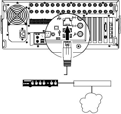
NETWORK SETUP
The DX8100 Series DVR supports remote viewing and administration in client-server and peer-to-peer configurations. The DX8100 is compatible with the TCP/IP protocol and Fast Ethernet (1000BaseT) network connection. Consult your network administrator before installing the DX8100 to avoid possible network conflicts.
For TCP/IP access, connect the DX8100 to a 100 Mbps or 1 Gigabit, switched Ethernet network. Use standard Cat5 or better UTP cable with RJ-45 connectors.
To configure the DX8100 hardware for network access:
1.Connect one end of the UTP cable to the network port on the back panel of the DX8100 as shown in Figure 10.
2.Connect the other end of the UTP cable to an available port on a standard Fast Ethernet switch.
|
IN1 |
|
|
IN2 |
|
IN3 |
|
|
IN4 |
|
|
|
IN5 |
|
IN6 |
IN7 |
IN8 |
IN9 |
IN10 |
IN11 |
IN12 |
IN13 |
IN14 |
IN15 |
IN16 |
|
OUT1 |
|
|
OUT2 |
|
OUT3 |
|
OUT4 |
|
OUT5 |
OUT6 |
OUT7 |
OUT8 |
OUT9 |
OUT10 |
OUT11 |
OUT12 |
OUT13 |
OUT14 |
OUT15 |
OUT16 |
||||||
ALARM INPUTS |
|
|
|
RELAY OUTPUTS |
|
|
|
|
|
|
|
|
|
|
|
|
|
|
||||||||
1 |
2 |
2 |
4 |
5 |
6 |
7 |
8 GND |
1 |
2 |
2 |
4 |
5 |
6 |
7 |
8 |
GND |
|
|
|
|
|
|
|
|
|
|
9 |
10 |
11 |
12 |
13 |
14 |
15 |
16 |
9 |
10 |
11 |
12 |
13 |
14 |
15 |
16 |
|
|
|
|
|
|
|
|
|
|
|
 CAT5 UTP
|
|
|
|
|
|
|
|
|
|
|
|
|
|
|
|
|
|
|
|
|
|
|
|
|
|
|
|
FAST ETHERNET SWITCH |
ROUTER |
||||||||||||
LAN/WAN
INTERNET
Figure 10. LAN/WAN Cable Connection
RS-422/RS-485 COMMUNICATION PORT SETUP
The DX8100 Series DVR features four RS-422/ RJ-45 communication ports. All ports are compatible with both RS-422 and RS-485 interface standards. Each port can communicate with and control a variety of ATM/POS, PTZ, third-party dome devices, and Pelco’s Spectra™ III dome enclosures and Esprit® positioning systems.
The example configuration illustrated in Figure 11 shows a DX8100 connected directly to up to four PTZ devices and indirectly to up to 16 devices through Pelco’s CM9760-CDU-T code distribution unit. Figure 12 illustrates the connection of a variety of RS-422/RS-485 compatible devices including the DX8100. This example highlights the P and D protocol data merging capability of Pelco’s CM9760-DMR data manager.
To operate properly, devices must be compatible with either the RS-422 or RS-485 interface standards and must be able to communicate using Pelco’s P, D, or Coaxitron® protocols, or third-party dome protocols.
1.Using unshielded twisted pair (UTP) cable, connect up to four RS-422/RS-485 compatible devices to the RJ-45 connector jacks provided on the rear panel of the unit.
You should use 22 or 24 gauge UTP cable. Category 5 UTP is recommended for cable runs greater than 400 feet.
2.Set the communication parameters for both the DX8100 and the PTZ device. Communication parameters are baud rate, parity (odd or even), number of parity bits, number of data bits, and number of stop bits.
Refer to RS-422/RS-485 Communication Port Software Configuration for instructions on setting up your DVR’s communication parameters. Refer to the documentation included with your PTZ device for instructions on configuring its communication settings.
22 |
C2629M-A (6/07) |

|
IN1 |
|
IN2 |
IN3 |
|
IN4 |
|
IN5 |
|
IN6 |
IN7 |
IN8 |
IN9 |
IN10 |
IN11 |
IN12 |
IN13 |
IN14 |
IN15 |
IN16 |
|
OUT1 |
|
OUT2 |
OUT3 |
|
OUT4 |
OUT5 |
OUT6 |
OUT7 |
OUT8 |
OUT9 |
OUT10 |
OUT11 |
OUT12 |
OUT13 |
OUT14 |
OUT15 |
OUT16 |
||||
ALARM INPUTS |
|
|
RELAY OUTPUTS |
|
|
|
|
|
|
|
|
|
|
|
|
|
|
||||
1 |
2 |
2 4 |
5 |
6 7 |
8 GND |
1 |
2 2 4 5 |
6 |
7 |
8 |
GND |
|
|
|
|
|
|
|
|
|
|
9 |
10 |
11 12 |
13 |
14 15 |
16 |
9 |
10 11 12 13 |
14 |
15 |
16 |
|
|
|
|
|
|
|
|
|
|
|
PIN 8
PIN 1
|
|
|
|
|
|
|
|
|
|
|
|
|
|
|
ROLLOVER CABLE |
|
|
|
|
|
|
|
|
|
|
|
PIN 1 = TX+ |
||||
|
|
|
|
|
|
|
|
|
|
|
|
|
|
|
|
|
|
|
|
|
|
|
|
|
|
|
|
|
|
|
PIN 2 = TX- |
|
|
|
|
|
|
|
|
|
|
|
|
|
|
|
|
|
|
|
|
|
|
|
|
|
|
|
|
|
|
|
. |
|
|
|
|
|
|
|
|
|
|
|
|
|
|
|
|
|
|
|
|
|
|
|
|
|
|
|
|
|
|
|
. |
|
|
|
|
|
|
|
|
|
|
|
|
|
|
|
|
|
|
|
|
|
|
|
|
|
|
|
|
|
|
|
|
|
|
|
|
|
|
|
|
|
|
|
|
|
|
|
|
|
|
|
|
|
|
|
|
|
|
|
PIN 8 |
|
|
|
. |
CM9760-CDU-T |
|
|
|
|
|
|
|
|
|
|
|
|
|
|
|
|
|
|
|
|
|
. |
|||||||||
|
|
|
|
|
|
|
|
|
|
|
|
|
|
|
|
|
|
|
|
|
|
||||||||||
|
|
|
|
|
|
|
|
|
|
|
|
|
|
|
|
|
|
|
|
|
|
||||||||||
|
|
|
|
|
|
|
|
|
|
|
|
|
|
|
|
|
|
|
|
|
|
||||||||||
|
|
|
|
|
|
|
|
|
|
|
|
|
|
|
|
|
|
|
SPECTRA |
PIN 7 = RX- |
|||||||||||
|
|
|
|
|
|
|
|
|
|
|
|
|
|
|
|
|
|
|
|||||||||||||
|
|
|
|
|
|
|
|
|
|
|
|
|
|
|
|
|
|
|
|||||||||||||
|
|
|
|
|
|
|
|
|
|
|
|
|
|
|
|
|
|
|
|
|
|
|
|
|
|
|
|
||||
|
|
|
|
|
|
|
|
|
|
|
|
|
|
|
|
|
|
|
|
|
|
|
|
|
|
|
|
||||
|
|
|
|
|
|
|
|
|
|
|
|
|
|
|
|
|
|
|
|
|
|
|
|
|
|
|
|
||||
|
|
|
|
|
|
|
|
|
|
|
|
|
|
|
|
|
|
|
|
|
|
|
|
|
|
|
PIN 1 |
PIN 8 = RX+ |
|||
|
|
|
|
|
|
|
|
|
|
|
|
|
|
|
|
|
|
|
|
|
|
|
|
|
|
|
|||||
|
|
|
|
|
|
|
|
|
|
|
|
|
|
|
|
|
|
|
|
|
|
|
|
|
|
|
|||||
|
|
|
|
|
|
|
|
|
|
|
|
|
|
|
|
|
|
|
|
|
|
|
|
|
|
|
|
|
|
||
|
|
|
|
|
|
|
|
|
|
|
|
|
|
|
|
|
|
|
|
|
|
|
|
|
|
|
|
|
|
||
|
|
|
|
|
|
|
|
|
|
|
|
|
|
|
|
|
|
|
|
|
|
PIN 1 = TX+ |
|
|
|
|
|||||
|
|
|
|
|
|
|
|
|
|
|
|
|
|
|
|
|
|
|
|
|
|
PIN 2 = TX- |
|
|
|
|
|||||
|
|
|
|
|
|
|
|
|
|
|
|
|
|
|
|
|
|
|
|
|
|
|
|
||||||||
|
|
|
|
|
|
|
|
|
|
|
|
|
|
|
|
|
|
|
|
. |
|
|
|
|
|
|
|
|
|||
|
|
|
|
|
|
|
|
|
|
|
|
|
|
|
|
|
|
|
|
. |
|
|
|
|
|
|
|
|
|||
|
|
|
|
|
|
|
|
|
|
|
|
|
|
|
|
|
|
|
|
. |
|
|
|
|
|
|
|
|
|||
|
|
|
PTZ |
|
PTZ |
|
|
PTZ |
. |
|
|
|
|
|
|
|
|
||||||||||||||
|
|
|
|
|
|
|
|
|
|
|
|
|
|
|
|
|
|
||||||||||||||
PIN 7 = RX-
PIN 8 = RX+
Figure 11. RS-422/RS-485 Configuration Example 1
|
CM9760-DMR |
CM6800 |
PTZ |
|
1-16 |
KBD300A
ROLLOVER CABLE
CM6800
|
IN1 |
|
|
IN2 |
|
IN3 |
|
|
IN4 |
|
|
|
IN5 |
|
IN6 |
IN7 |
IN8 |
IN9 |
IN10 |
IN11 |
IN12 |
IN13 |
IN14 |
IN15 |
IN16 |
|
OUT1 |
|
|
OUT2 |
|
OUT3 |
|
OUT4 |
|
OUT5 |
OUT6 |
OUT7 |
OUT8 |
OUT9 |
OUT10 |
OUT11 |
OUT12 |
OUT13 |
OUT14 |
OUT15 |
OUT16 |
||||||
ALARM INPUTS |
|
|
|
RELAY OUTPUTS |
|
|
|
|
|
|
|
|
|
|
|
|
|
|
||||||||
1 |
2 |
2 |
4 |
5 |
6 |
7 |
8 GND |
1 |
2 |
2 |
4 |
5 |
6 |
7 |
8 |
GND |
|
|
|
|
|
|
|
|
|
|
9 |
10 |
11 |
12 |
13 |
14 |
15 |
16 |
9 |
10 |
11 |
12 |
13 |
14 |
15 |
16 |
|
|
|
|
|
|
|
|
|
|
|
Figure 12. RS-422/RS-485 Configuration Example 2
C2629M-A (6/07) |
23 |
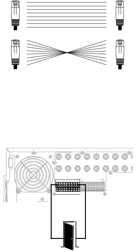
Different types of devices may require alternative cable wiring schemes. Wiring schemes commonly used by Pelco products include straight and rollover types. Refer to the documentation included with your PTZ device to ensure that cables and connectors are wired appropriately. Figure 13 illustrates straight and rollover cable wiring schemes.
|
PIN |
PIN |
|
|
|
1 |
1 |
|
|
|
2 |
2 |
|
|
|
3 |
3 |
|
|
RJ-45 |
4 |
4 |
RJ-45 |
|
5 |
5 |
|||
|
|
|||
|
6 |
6 |
|
|
|
7 |
7 |
|
|
|
8 |
8 |
|
|
|
|
STRAIGHT CABLE |
|
|
|
PIN |
PIN |
|
|
|
1 |
1 |
|
|
|
2 |
2 |
|
|
|
3 |
3 |
|
|
RJ-45 |
4 |
4 |
RJ-45 |
|
5 |
5 |
|||
|
6 |
6 |
|
|
|
7 |
7 |
|
|
|
8 |
8 |
|
|
|
|
ROLLOVER CABLE |
|
Figure 13. Cable Wiring Schemes
ALARM INPUT INSTALLATION
The DX8100 has either 8 or 16 dry contact alarm inputs, depending on your system’s configuration. Each input is programmed to function as either a normally open or normally closed circuit.
To wire an alarm input:
1.Insert the green terminal blocks into the alarm sockets on the back panel of the recorder.
2.Connect one wire from the source device to one of the sensor input terminals 1 through 16.
3.Connect a second wire from the source device to a GND terminal.
4.Refer to the DX8100 Operation/Programming manual for information on how to program the alarm inputs.
|
IN1 |
|
|
IN2 |
|
|
IN3 |
|
|
IN4 |
|
|
|
IN5 |
|
IN6 |
IN7 |
IN8 |
IN9 |
|
OUT1 |
|
|
OUT2 |
|
|
OUT3 |
|
OUT4 |
|
OUT5 |
OUT6 |
OUT7 |
OUT8 |
OUT9 |
||||||
ALARM INPUTS |
|
|
|
|
RELAY OUTPUTS |
|
|
|
|
|
|
|
||||||||
1 |
2 |
2 |
4 |
5 |
6 |
7 |
8 |
GND |
1 |
2 |
2 |
4 |
5 |
6 |
7 |
8 |
GND |
|
|
|
9 |
10 |
11 |
12 |
13 |
14 |
15 |
16 |
|
9 |
10 |
11 |
12 |
13 |
14 |
15 |
16 |
|
|
|
|
ALARM |
|
|
|
|
|
|
|
|
|
|
GND |
|
|
|
|
|
|
|
||
OUTPUT 1 |
|
|
|
|
|
|
|
|
|
|
|
|
|
|
|
|
|
|||
|
|
|
|
|
|
|
|
|
|
|
|
|
|
|
|
|
|
|
|
|
Figure 14. Alarm Terminal Installation
24 |
C2629M-A (6/07) |
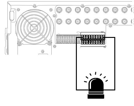
RELAY OUTPUT INSTALLATION
The DX8100 has either 8 or 16 relay outputs, depending on your system’s configuration. Each output is programmed to function as either a normally open or normally closed circuit. A signal from a relay output will operate the device connected to the output. The maximum relay power rating is 120 VAC, 0.5 A; 24 VDC, 1 A.
To wire a relay output:
1.Insert the blue terminal blocks into the relay sockets on the back panel of the recorder.
2.Connect one wire from the device to one of the relay output terminals 1 through 16.
Relay outputs do not have to correspond numerically to alarm inputs. All sensor input and relay output actions can be linked through programming.
3.Connect a second wire from the relay device to a GND terminal.
4.Refer to the DX8100 Operation/Programming manual for information on how to program relay outputs.
|
IN1 |
|
|
IN2 |
|
|
IN3 |
|
|
IN4 |
|
IN5 |
|
IN6 |
IN7 |
IN8 |
IN |
|
OUT1 |
|
|
OUT2 |
|
|
OUT3 |
|
OUT4 |
OUT5 |
|
OUT6 |
OUT7 |
OUT8 |
OU |
||||
ALARM INPUTS |
|
|
|
|
RELAY OUTPUTS |
|
|
|
|
|
|
|||||||
1 |
2 |
2 |
4 |
5 |
6 |
7 |
8 |
GND |
1 |
2 |
2 |
4 5 |
6 7 |
8 |
GND |
|
|
|
9 |
10 |
11 |
12 |
13 |
14 |
15 |
16 |
|
9 |
10 |
11 |
12 13 14 15 16 |
|
|
|
|
||
|
|
|
|
RELAY |
|
|
|
|
|
|
|
|
|
GND |
|
|
||
|
|
OUTPUT 1 |
|
|
|
|
|
|
|
|
|
|
|
|||||
|
|
|
|
|
|
|
|
|
|
|
|
|
|
|||||
Figure 15. Relay Terminal Installation
C2629M-A (6/07) |
25 |
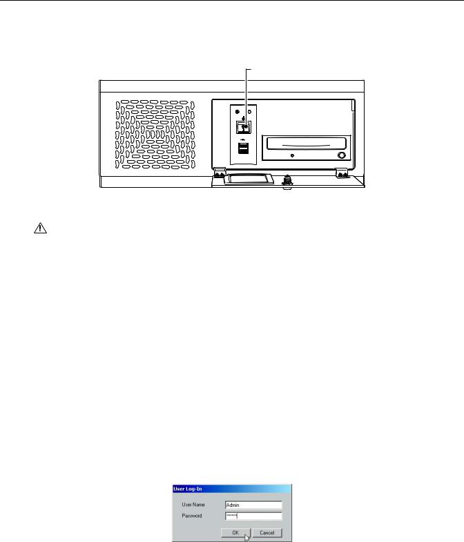
Software Setup
STARTING THE UNIT
Once the system has been installed and basic connections have been made, open the front panel of the DVR. Press the power switch. Wait while the unit starts (this may take several minutes).
POWER SWITCH
POWER HDD
USB
Figure 16. Front Panel and Power Switch
WARNING: Be sure to put on gloves before removing or inserting the filter.
LOGGING IN FOR THE FIRST TIME
To access the features of the DX8100 Series DVR, each user must log in with a valid user name and password. User names and passwords are case sensitive.
There are four user access levels or groups that can be configured on the DX8100. Access levels range from the Administrator group, with the most rights and privileges, to the Restricted group, with the least rights and privileges. For information about configuring access levels, refer to the Definition of User Access Levels section of the DX8100 Operation/Programming manual for information on user group rights and permissions.
The DX8100 comes equipped with two built-in user accounts. Each time the unit is started, a default user account called “Guest” is automatically activated. The Guest account is granted only limited access to the DX8100 and is allowed no access to system configuration utilities. A second built-in user account, named “Admin”, provides full access to the operations and configuration features of the DX8100.
For security reasons, you are prompted but not required to change the Admin password immediately after logging in for the first time. Passwords must be between six and ten characters long and cannot include spaces or special characters. Follow the directions on the next page to change the Admin password.
To log in with the Admin account:
1.Click File > User Log-in.
2.Enter Admin in the User name field and Admin in the Password field.
3.Click OK.
Figure 17. User Log-in Dialog Box
If you are logging in for the first time, the system prompts you to complete the mandatory password change for the Admin account. In this case, the Set Admin Password dialog box opens automatically. You must change the password for the Admin account. If you want to keep the default password, click cancel. However, because of security reasons, Pelco recommends that you change the password.
26 |
C2629M-A (6/07) |
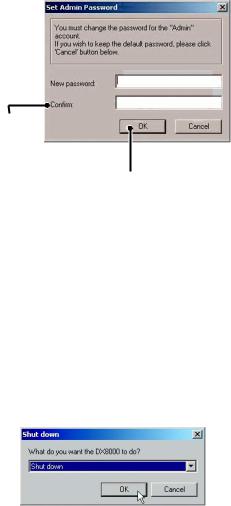
Only users with Administrator and Power User accounts are allowed access to DX8100’s setup functions.
To complete the prompted password change for the Admin account:
1.Enter a new password in the New Password field.
2.Enter the password again in the Confirm Password field to confirm the password.
3.Click OK.

Figure 18. Set Admin Password Dialog Box
SHUTTING DOWN
You must have Power User or Administrator access to shut down the DX8100. For more information about user security levels, refer to the DX8100 Operation/Programming manual. You must also have a Windows password to shut down the DX8100. For information on the Windows default password, refer to the Important Security Information for System Administrators guide.
To shut down the DX8100 Series DVR:
1.Go to File > Exit.
2.Select Shut down.
3.Click OK.
Figure 19. Shut Down Dialog Box
EXITING TO WINDOWS OPERATING SYSTEM
Some of the steps involved in the configuration of a DX8100 Series DVR require exiting to the operating system. You must have Administrator access to exit to the Windows operating system. For more information about user security levels, refer to the DX8100 Operation/Programming manual. You must also have a password to exit from the DX8100 application to the Windows operating system. For information on the Windows default password, refer to the Important Security Information for System Administrators guide.
To exit the DX8100 application and log into the Windows operating system:
1.Go to File > Exit.
2.Select Exit to Windows. The Shut down dialog box opens.
C2629M-A (6/07) |
27 |
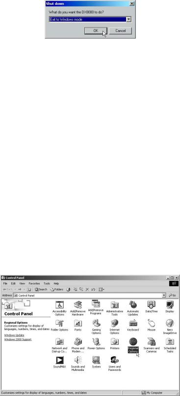
3. Click OK.
Figure 20. Shut Down Dialog Box
The Log On to Windows dialog box opens.
4. Enter the Windows password and click OK. The system logs you into the Windows operating system.
SETTING THE SYSTEM LANGUAGE
The DX8100 supports eight languages. The DVR comes from the factory configured for English (United States). To configure the system properly for a language other than English, you must change the regional setting in the Windows operating system and the language setting of the DX8100. The following regional settings are available for the DX8100:
•English (United States)
•French (France)
•German (Germany)
•Italian (Italy)
•Polish
•Portuguese (Brazil)
•Russian
•Spanish (Spain)
English (United States) is the default setting.
CONFIGURING THE REGIONAL SETTING IN THE WINDOWS OPERATING SYSTEM
In the example below, the location is changed from English (United States) to Spanish (Spain).
1.Exit the DX8100 application and return to the Windows operating system. Refer to Exiting to Windows Operating System.
2.Click Start > Settings > Control Panel. The Control Panel appears. Double-click Regional Options.
Figure 21. Control Panel with Regional Options Selected
28 |
C2629M-A (6/07) |
 Loading...