


I N S T A L L A T I O N / O P E R A T I O N
|
CM6800-32X6 |
® |
Matrix Switcher |
|
|
C1522M-C (2/05)

CONTENTS
Section |
Page |
IMPORTANT SAFEGUARDS AND WARNINGS .................................................................................................................................................................. |
6 |
DESCRIPTION ..................................................................................................................................................................................................................... |
7 |
MODELS ................................................................................................................................................................................................................... |
10 |
ASSOCIATED EQUIPMENT .............................................................................................................................................................................. |
10 |
COMPATIBLE PRODUCTS ......................................................................................................................................................................................... |
10 |
ADDITIONAL RESOURCES ........................................................................................................................................................................................ |
10 |
INSTALLATION ................................................................................................................................................................................................................... |
11 |
MOUNTING .............................................................................................................................................................................................................. |
11 |
VIDEO SOURCES ....................................................................................................................................................................................................... |
12 |
CONTROL LINES ....................................................................................................................................................................................................... |
14 |
MONITORS ............................................................................................................................................................................................................... |
15 |
ALARMS ................................................................................................................................................................................................................... |
16 |
CONNECTING DEVICES THROUGH THE COMMUNICATION PORTS ....................................................................................................................... |
17 |
KBD100, KBD200A, AND KBD300A SERIES KEYBOARDS .............................................................................................................................. |
19 |
KBD100, KBD200A, AND KBD300A: DIRECT-POWERED KEYBOARD ............................................................................................................. |
19 |
KBD100, KBD200A, AND KBD300A: REMOTE KEYBOARDS .......................................................................................................................... |
21 |
M DEVICES ...................................................................................................................................................................................................... |
22 |
CONNECTING A PC ......................................................................................................................................................................................... |
27 |
CONNECTING GENEX MULTIPLEXERS ............................................................................................................................................................ |
28 |
LOCAL AUXILIARIES ................................................................................................................................................................................................. |
29 |
SYSTEM START-UP ............................................................................................................................................................................................................ |
31 |
POWER-UP THE SYSTEM ......................................................................................................................................................................................... |
31 |
INITIALIZE KEYBOARDS ........................................................................................................................................................................................... |
31 |
CONFIGURE THE SYSTEM ........................................................................................................................................................................................ |
31 |
COMMUNICATION PORTS .............................................................................................................................................................................. |
32 |
KBD960/KBR960 KEYBOARD .......................................................................................................................................................................... |
32 |
GENEX MULTIPLEXER ...................................................................................................................................................................................... |
32 |
MONITOR COLOR ADJUSTMENT: ................................................................................................................................................................... |
33 |
PROGRAM PRESETS ........................................................................................................................................................................................ |
33 |
ADDITIONAL PROGRAMMING ........................................................................................................................................................................ |
33 |
PROGRAMMING THE CM6800 ......................................................................................................................................................................................... |
34 |
CM6800 PROGRAMMING MODE ............................................................................................................................................................................ |
35 |
NAVIGATE AND SELECT OPTIONS/FIELD ENTRIES IN PROGRAMMING MODE ............................................................................................ |
36 |
ACCESS .................................................................................................................................................................................................................... |
38 |
ALARM PROGRAMMING ......................................................................................................................................................................................... |
39 |
PROGRAM ALARM GROUPS ........................................................................................................................................................................... |
39 |
INTERNAL AND EXTERNAL ALARMS ............................................................................................................................................................. |
40 |
PROGRAM A VIDEO LOSS ALARM ................................................................................................................................................................. |
41 |
AUXILIARY OUTPUTS ............................................................................................................................................................................................... |
42 |
CAMERA PROGRAMMING ....................................................................................................................................................................................... |
43 |
PROGRAM LOGICAL NUMBERS ...................................................................................................................................................................... |
43 |
PROGRAM CAMERAS ..................................................................................................................................................................................... |
44 |
EVENT TIMERS ......................................................................................................................................................................................................... |
46 |
MACRO ..................................................................................................................................................................................................................... |
47 |
MACRO STATUS VIEW SCREEN ..................................................................................................................................................................... |
47 |
MONITOR DISPLAY .................................................................................................................................................................................................. |
48 |
PASSWORD .............................................................................................................................................................................................................. |
50 |
PORTS (SERIAL/COM PORTS) .................................................................................................................................................................................. |
51 |
PRIORITY ................................................................................................................................................................................................................... |
52 |
SEQUENCE ................................................................................................................................................................................................................ |
52 |
TIME AND DATE ....................................................................................................................................................................................................... |
54 |
PATTERNS, PRESETS, AND ZONES .......................................................................................................................................................................... |
54 |
2 |
C1522M-C (2/05) |
OPERATION ........................................................................................................................................................................................................................ |
55 |
OVERVIEW ................................................................................................................................................................................................................ |
55 |
OPERATING THE CM6800 ......................................................................................................................................................................................... |
55 |
SWITCH MONITORS ....................................................................................................................................................................................... |
55 |
SELECT CAMERAS .......................................................................................................................................................................................... |
56 |
CONTROL RECEIVERS ...................................................................................................................................................................................... |
56 |
OPERATE SEQUENCES ..................................................................................................................................................................................... |
57 |
RUN A MACRO ................................................................................................................................................................................................ |
58 |
ACKNOWLEDGE AN ALARM .......................................................................................................................................................................... |
58 |
CALL A PRESET ................................................................................................................................................................................................ |
59 |
CREATE AND RUN A PATTERN ....................................................................................................................................................................... |
59 |
OPERATE AUXILIARIES/RELAYS ...................................................................................................................................................................... |
60 |
CONTROL GENEX MULTIPLEXER AND GENEX MULTIPLEXER DISPLAYS ....................................................................................................... |
61 |
OPERATE SCANNING FUNCTIONS ................................................................................................................................................................. |
61 |
DETECT VIDEO LOSS ....................................................................................................................................................................................... |
61 |
DEFINE ZONES ................................................................................................................................................................................................ |
61 |
APPENDIX .......................................................................................................................................................................................................................... |
62 |
CM6800 DIP SWITCHES ........................................................................................................................................................................................... |
62 |
ALARM GROUP DISPLAY OPTIONS ................................................................................................................................................................. |
63 |
MACRO COMMANDS .............................................................................................................................................................................................. |
65 |
ASCII OPERATING COMMANDS .............................................................................................................................................................................. |
67 |
TROUBLESHOOTING ................................................................................................................................................................................................. |
70 |
GAINING INITIAL CONTROL ............................................................................................................................................................................ |
70 |
SOFTWARE RESET ........................................................................................................................................................................................... |
70 |
SOLUTIONS TO COMMON PROBLEMS .......................................................................................................................................................... |
71 |
KBD960/KBR960 ICON/BUTTON LEGEND ............................................................................................................................................................... |
72 |
GLOSSARY ......................................................................................................................................................................................................................... |
73 |
INDEX ................................................................................................................................................................................................................................ |
76 |
SPECIFICATIONS ................................................................................................................................................................................................................ |
78 |
REGULATORY NOTICES ..................................................................................................................................................................................................... |
79 |
WARRANTY AND RETURN INFORMATION ...................................................................................................................................................................... |
79 |
C1522M-C (2/05) |
3 |
LIST OF ILLUSTRATIONS |
|
|
Figure |
|
Page |
1 |
Sample CM6800-32X6 System ........................................................................................................................................................................ |
7 |
2 |
Installing Rack Ears ......................................................................................................................................................................................... |
11 |
3 |
Mounting the CM6800 Matrix Switcher/Controller ....................................................................................................................................... |
11 |
4 |
CM6800-32X6 Video Inputs ............................................................................................................................................................................. |
12 |
5 |
Connecting Terminated Video Sources ........................................................................................................................................................... |
13 |
6 |
Connecting Looping Video Sources ................................................................................................................................................................. |
13 |
7 |
PTZ Control Connections ................................................................................................................................................................................. |
14 |
8 |
Connecting Monitors ....................................................................................................................................................................................... |
15 |
9 |
Connecting Alarms .......................................................................................................................................................................................... |
16 |
10 |
Communication Port Inputs ............................................................................................................................................................................. |
17 |
11 |
CM6800-32X6 Communication Port Connections and Options ...................................................................................................................... |
18 |
12 |
Data Cable Plugged into Local Keyboard ........................................................................................................................................................ |
19 |
13 |
Data Cable Plugged into COM 5 ..................................................................................................................................................................... |
19 |
14 |
Remote Keyboards .......................................................................................................................................................................................... |
21 |
15 |
RJ-45 Cable Types ........................................................................................................................................................................................... |
22 |
16 |
Connecting a KBD960/KBR960 to the CM6800-32X6 ..................................................................................................................................... |
23 |
17 |
Connecting a Single ALM2064 Alarm Interface Unit ...................................................................................................................................... |
24 |
18 |
Connecting a Single REL2064 Relay Interface Unit ........................................................................................................................................ |
24 |
19 |
Connecting Multiple M Devices – Local Connection ...................................................................................................................................... |
25 |
20 |
Connecting Multiple M Devices – Remote Connection .................................................................................................................................. |
26 |
21 |
PC Connection to DB9 Port .............................................................................................................................................................................. |
27 |
22 |
Connecting Genex Multiplexers ...................................................................................................................................................................... |
28 |
23 |
Wiring the AUX 1 (Relay) Output .................................................................................................................................................................... |
29 |
24 |
Wiring the F2 (TTL) Output .............................................................................................................................................................................. |
30 |
25 |
CM6800 Time/Date Stamp on Monitor ........................................................................................................................................................... |
31 |
26 |
CM6800 Color Bars ......................................................................................................................................................................................... |
33 |
27 |
CM6800 Password Screen .............................................................................................................................................................................. |
35 |
28 |
CM6800 Programming Main Menu ................................................................................................................................................................. |
35 |
29 |
Sample Access Screen .................................................................................................................................................................................... |
38 |
30 |
Program Alarm Groups .................................................................................................................................................................................... |
39 |
31 |
Program an Internal or External Alarm Screen ............................................................................................................................................... |
40 |
32 |
Program Video Loss Alarms ............................................................................................................................................................................. |
41 |
33 |
Program Auxiliary Outputs .............................................................................................................................................................................. |
42 |
34 |
Program Logical Camera Numbers .................................................................................................................................................................. |
43 |
35 |
Program Cameras ............................................................................................................................................................................................ |
44 |
36 |
Sample Event Timer Programming .................................................................................................................................................................. |
46 |
37 |
Access the Macro Screen ............................................................................................................................................................................... |
47 |
38 |
Macro Status View Screen .............................................................................................................................................................................. |
47 |
39 |
Access the Monitor Screen ............................................................................................................................................................................. |
48 |
40 |
Access the Set Password Screen .................................................................................................................................................................... |
50 |
41 |
Access the Port Screen ................................................................................................................................................................................... |
51 |
42 |
Access the Priority Screen .............................................................................................................................................................................. |
52 |
43 |
Sequence Screen ............................................................................................................................................................................................. |
52 |
44 |
Scratchpad Sequence Screen ......................................................................................................................................................................... |
53 |
45 |
Access the Time and Date Screen .................................................................................................................................................................. |
54 |
46 |
CM6800 DIP Switches – Factory Default Settings ......................................................................................................................................... |
62 |
47 |
Dip Switch Cover Plate .................................................................................................................................................................................... |
70 |
48 |
CM6800 DIP Switch 7 ..................................................................................................................................................................................... |
70 |
49 |
Icon/Button Legend ......................................................................................................................................................................................... |
72 |
4 |
C1522M-C (2/05) |
LIST OF TABLES |
|
|
Table |
|
Page |
A |
Video Coaxial Cable Requirements ................................................................................................................................................................. |
12 |
B |
Communication Port Devices and Wiring ....................................................................................................................................................... |
17 |
C |
Default Port Settings ....................................................................................................................................................................................... |
18 |
D |
Keyboard Addresses: KBD100/200A/300A Series Keyboards ....................................................................................................................... |
20 |
E |
Switch Settings – KBD200A/300A Keyboards Only ....................................................................................................................................... |
20 |
F |
Default Port Settings ....................................................................................................................................................................................... |
32 |
G |
CM6800 DIP Switch Settings .......................................................................................................................................................................... |
62 |
H |
Macro Commands ........................................................................................................................................................................................... |
65 |
I |
Examples of ASCII Commands ........................................................................................................................................................................ |
67 |
J |
ASCII Commands ............................................................................................................................................................................................. |
68 |
K |
Solutions To Common Problems ...................................................................................................................................................................... |
71 |
C1522M-C (2/05) |
5 |

IMPORTANT SAFEGUARDS AND WARNINGS
1.Read, keep, and follow these instructions.
2.Heed all warnings.
3.There are no user-serviceable parts inside this unit. Only authorized service personnel may open the unit.
4.Installation and servicing should only be done by qualified service personnel and conform to all local codes.
5.WARNING: To reduce the risk of fire or electric shock, do not expose this unit to rain or moisture if this unit is designed for indoor use only.
6.Unless this unit is specifically marked as a NEMA Type 3, 3R, 3S, 4, 4X, 6 or 6P enclosure, it is designed for indoor use only and it must not be installed where exposed to rain or moisture.
7.Do not expose this unit to dripping or splashing. Do not place objects filled with liquids, such as vases, on this unit.
8.Do not block any ventilation openings. Install in accordance with the manufacturer’s instructions.
9.The installation method and materials should be capable of supporting four times the weight of the unit and equipment.
10.Do not install near any heat source.
11.Only use attachments/accessories specified by the manufacturer.
12.Clean only with dry cloth.
13.Do not defeat the safety purpose of the polarized or grounding-type plug.
14.Protect the power cord from being walked on or pinched, particularly at plugs, convenience receptacles, and the point where they exit from the unit.
15.Unplug this unit during lightning storms or when unused for long periods of time.
The product and/or manual may bear the following marks:
This symbol indicates that dangerous voltage constituting a risk of electric shock is present within this unit.
This symbol indicates that there are important operating and maintenance instructions in the literature accompanying this unit.
CAUTION:
RISK OF ELECTRIC SHOCK.
DO NOT OPEN.
Please thoroughly familiarize yourself with the information in this manual prior to installation and operation.
FOR QUALIFIED SERVICE PERSONNEL ONLY
1.Only use replacement parts recommended by Pelco.
2.After replacement/repair of this unit’s electrical components, conduct a resistance measurement between line and exposed parts to verify the exposed parts have not been connected to line circuitry.
3.CAUTION: Danger of explosion if battery is incorrectly replaced. Replace only with the same or equivalent type. Dispose of used batteries according to the instructions provided by the battery manufacturer.
6 |
C1522M-C (2/05) |

DESCRIPTION
Pelco’s CM6800 Matrix Switcher/Controller is a cross-point video matrix switcher. The CM6800-32X6 provides switching and control for 32 video inputs and six monitor outputs from any one of up to 10 keyboards, PCs, and other devices. All 32 video inputs can be used to control other devices, such as multiplexers, and allow for looping to other devices.
CM9505UPS
ESPRIT®
KBD960
CC3500H-2
SPECTRA®
KBD300A
VIDEO TO
SWITCHER
|
|
|
|
|
|
|
|
|
|
|
|
|
|
|
|
|
010101 |
|
|
|
|
|
|
|
|
|
HZ |
|
|
|
|
|
|
|
|
|
|
|
|
|
|
|
|
|
1 |
2 |
3 |
4 |
5 |
6 |
7 |
8 |
|
1 |
2 |
3 |
4 |
5 |
6 |
7 |
8 |
9 |
10 |
11 |
12 |
13 |
14 |
15 |
16 |
|
|
|
|
|
|
|
|
|
|
|
75 |
|
|
|
|
|
|
|
|
|
|
|
|
|
|
|
2 |
|
|
|
|
|
|
|
|
|
|
|
|
|
|
|
|
|
|
|
|
|
|
|
|
|
|
|
|
|
|
|
|
|
|
|
|
|
|
|
|
|
|
|
|
|
|
|
|
|
|
|
|
|
|
|
|
|
|
|
CONTROL |
|
|||
|
|
|
|
|
|
|
|
|
|
|
|
|
|
|
|
3 |
OR |
|
|
|
|
|
|
|
|
|
|
|
|
|
|
|
|
|
|
|
|
|
|
|
|
|
|
T |
T |
|
|
R R |
|
|
|
||
|
|
|
|
|
|
|
|
|
|
|
|
|
|
|
|
|
|
|
|
|
2 |
|
||||
|
|
|
|
|
|
|
|
|
|
|
|
|
|
|
|
|
|
+ |
- |
|
|
- |
+ |
|
|
|
17 |
18 |
19 |
20 |
21 |
22 |
23 |
24 |
25 |
26 |
27 |
28 |
29 |
30 |
31 |
32 |
4 |
|
|
|
|
|
|
|
|
|
|
|
|
|
|
|
|
|
|
|
|
|
|
1 |
2 |
3 |
|
5 |
|
|
|
|
|
|
|
|
SPECTRA |
® |
|
|
|
|
|
|
|
|
|
|
|
|
|
|
|
|
|
|
|
|
|
|
|
||||
|
|
|
|
|
|
|
|
|
|
|
|
|
|
|
|
|
|
|
|
|
COM 1 |
|
|
|
|
|
|
|
|
|
|
|
|
|
|
|
|
|
4 |
5 |
6 |
|
|
|
|
|
|
|
|
|
|
|
|
|
|
|
|
|
|
|
|
|
|
|
|
|
|
|
|
|
|
|
|
|
|
|
|
|
120/230V~ |
|
|
|
|
|
|
|
|
|
|
|
|
|
|
|
|
|
|
|
|
|
|
|
|
|
|
50/60 HZ |
|
|
|
|
|
|
|
|
|
|
|
|
|
|
|
|
|
|
|
|
|
|
|
|
|
|
25 WATTS |
|
CAMCLOSURE®
SPOT |
MAIN |
VCR |
IN |
COM |
AUX |
|
OUT |
IN |
|
|
|
|
ALARMS |
|
OUT N NH 


 O C C S
110-240V 50/60 Hz
SVHS |
SVHS |
1 2 3 4 5 6 7 8 9 10 1112 1314 1516 |
GENEX® MULTIPLEXER
4 |
5 |
4 |
5 |
4 |
5 |
3 |
6 |
3 |
6 |
3 |
6 |
2 |
7 |
2 |
7 |
2 |
7 |
1 |
8 |
1 |
8 |
1 |
8 |
12V |
|
|
|
|
|
TRANSFORMER |
|
|
|
|
|
KBD100
KBD300A
KBD200A
4 5
3 6
2 7
1 


 8
8
MONITOR |
PC |
WALL
BLOCK
20005
ALTERNATE COM 4
CONNECTION
Figure 1. Sample CM6800-32X6 System
C1522M-C (2/05) |
7 |

Programming
The CM6800 features easy programming through on-screen menus or the Windows®-based CM6800-MGR software package. All programming is password-protected. Programming menus are provided in English, French, German, Italian, Polish, Portuguese, Russian, and Spanish.
Keyboards
Up to eight keyboards from the KBD100/200A/300A Series and two keyboards from the KBD960/KBR960 Series can be connected to the CM6800-32X6. Camera positioning can be programmed and controlled from the KBD200A/300A and KBD960/KBR960 Series keyboards. Refer to Associated Equipment for keyboard descriptions.
NOTE: You can program the CM6800 with the KBD200A/300A keyboard while in “CM6800 Mode” only (if you use “CM6800 ASCII Mode,” you can control the CM6800 switcher, but you cannot program it).
Sequences, Macros, Presets, Patterns, and Zones
The CM6800 features the following programmed operations:
Asequence allows operators to see a routine of 72 camera views on any system monitor over and over again. The sequence can be operated automatically or manually.
Ascratchpad sequence allows an operator to run a sequence from an individual monitor without entering the password-protected programming menus.
Amacro is a sequence of commands or steps. When a macro is run, the steps programmed into that macro are performed. Macros can be operated automatically or manually. Automatic operation can be based on specific times or dates. Macros can also be triggered by alarms.
The following operations are available only with positionable cameras controlled by KBD200A/KBD300A or KBD960/KBR960 keyboards:
A preset allows operators to direct a PTZ (camera positioning system) to move to a predetermined scene on keyboard command or as a result of an alarm. In addition, a preset can place a descriptive title on the monitor screen. The number of presets available is determined by the camera positioning system.
With a pattern operators can program a camera positioning system to move around its viewing area in a repeating pattern. The number and time length of patterns varies with different positioning systems.
A zone is a user-defined, physical location to which (1) a label is attached and (2) a camera is associated. When the associated camera is panned through or remains within this defined zone, the zone label appears on the monitor.
Interface Control
The CM6800 interfaces with the following:
•Coaxitron® standard mode (15-bit) and extended mode (32-bit) protocol receivers
•Pelco’s D and P protocol receivers (RS-422)
•Pelco’s M protocol devices (RS-485)
8 |
C1522M-C (2/05) |
System Access and Priority
The CM6800 provides the following ways to restrict system access:
•Camera to Monitor: Cameras can be assigned to specific monitors for viewing.
•Keyboard to Monitor: Keyboards can be assigned to control specific monitors.
•Camera to Keyboard:
-Viewing: Keyboards can be assigned view-only access to specific cameras (no PTZ control).
-Control: Keyboards can be assigned full access (both PTZ control and viewing) to specific cameras.
The CM6800 provides eight levels of priority control. Each level defines the ability of a keyboard to control a camera positioning system (KBD200A/KBD300A or KBD960/KBR960 only) and to access programming screens.
Alarm Inputs
Eight internal alarm inputs are provided on the rear panel of the matrix switcher/controller. These internal alarm inputs are programmable to associate any camera to any input.
Up to two ALM2064 Alarm Interface Units can be connected to the CM6800. Each alarm interface unit can handle up to 64 alarms, for a total of 128 external alarms.
Auxiliary Outputs
Two internal auxiliary outputs are provided on the back of the CM6800-32X6. One is a relay output, and one is an open collector (TTL) output. You can also connect up to two REL2064 Relay Interface Units.
Power, Mounting Methods
The CM6800 operates on 120V or 230V, 50/60 Hz. The case mounts in three rack units (5.25 inches or 13.34 cm) of vertical space in a universal mount, such as a 19-inch (48.26 cm) equipment bay, or to a wall or tabletop.
Continuous Operating Device
The CM6800 is a self-contained video surveillance system designed for continuous duty operation. Once installed, there are no user or service technician items that require intervention which would require the system to go off-line or have the power turned off under normal operation. There are two methods for system programming: direct menu control and indirect control, using a Windows®-based setup program supplied by Pelco. Both of these methods are noninvasive and do not require the cycling of power in order for storage or execution of new software settings. The communication ports use standard low voltage interfaces such as RS-232, RS-422 and RS-485, and all connections and disconnections do not require rebooting or power cycling. Video connections or changes of termination state do not require rebooting or power cycling.
C1522M-C (2/05) |
9 |
MODELS
CM6800-32X6 Matrix switcher/controller with 32 video inputs and 6 monitor outputs, NTSC configured 120/230 V, 50/60 Hz, autoranging
CM6800-32X6-X Matrix switcher/controller with 32 video inputs and 6 monitor outputs, PAL configured 120/230 V, 50/60 Hz, autoranging
ASSOCIATED EQUIPMENT
KBD100 |
Desktop keyboard with full switching and programming capabilities, +12 VDC or 12 V 50/60 Hz |
KBD200A |
Desktop keyboard with full switching and programming capabilities, plus push-button control of PTZ functions, |
|
+12 VDC or 12V 50/60 Hz |
KBD300A |
Desktop keyboard with full switching and programming capabilities, plus joystick control of PTZ functions, +12 VDC |
|
or 12 V 50/60 Hz |
KBD960 |
Full-function desktop variable speed keyboard; 120 V, 50/60 Hz |
KBD960-X |
Same as KBD960, PAL configured for 230 V, 50/60 Hz operation |
KBR960 |
Full-function rack mount variable speed keyboard; 120 V, 50/60 Hz |
KBR960-X |
Same as KBR960, PAL configured for 230 V, 50/60 Hz operation |
KBDKIT |
Wiring kit for connecting KBD100, KBD200A, and KBD300A keyboards to remote keyboard port; includes two RJ-45 |
|
wall blocks and a transformer to convert 120 V, 60 Hz to 12 V, 60 Hz for keyboard power |
KBDKIT-X |
Wiring kit for connecting KBD100, KBD200A, and KBD300A keyboards to remote keyboard port; includes two RJ-45 |
|
wall blocks and a transformer to convert 230 V, 50 Hz to 12 V, 50 Hz for keyboard power |
CM9505UPS |
Universal Power Supply for KBD960/KBR960 keyboards |
MX4000 |
Genex Series Multiplexer; available in color or monochrome duplex, and in color or monochrome simplex. |
CM9760-CDU-T |
Code distribution unit; 16-channel RS-422 transmit only (transmit wire and ground) distributor; primarily used for |
|
connecting up to 16 PTZ receivers in a “star” or “home run” configuration |
ALM2064 |
Alarm interface unit, provides alarm monitoring capabilities for up to 64 alarm inputs, 100-240 V, 50/60 Hz |
REL2064 |
Relay interface unit, provides 64 relays for operating peripheral equipment, 100-240 V, 50/60 Hz |
CM9760-MDA |
Master distribution amplifier with time, date, and title, 120 V, 60 Hz |
COMPATIBLE PRODUCTS
Switchers |
CM9740, CM9760, CM9770, CM9780 |
PelcoNet Transmission Systems |
NET300 Series, NET350 Series, NET4001A |
Video Management Systems |
VMX200, VMX300, VMX300-E |
ADDITIONAL RESOURCES |
|
•CM6800-32X6 Quick Start Guide
•CM6800-MGR Installation/Operation Manual
•Pelco Technical Tips available on Pelco.com or from a Technical Support representative (1-800-289-9100)
10 |
C1522M-C (2/05) |
INSTALLATION
Unpack and inspect all parts carefully. The following parts are supplied:
1CM6800 Switcher/Controller
410-32 x .750-inch pan head screws
4.500” OD nylon washers
1Power cord
26-foot (1.8 m) straight data cables with RJ-45 connectors 1 6-foot (1.8 m) reversed data cable with RJ-45 connectors
2RJ-45 wall block terminals
NOTE: There are no user-serviceable parts inside this unit. Only authorized service personnel may open the unit.
MOUNTING
1.Select a suitable location for the CM6800. It occupies 5.25 inches (13.34 cm) of vertical space, or three rack units (RUs), in a universal mount. The CM6800 must be within 6 feet (1.8 m) of a suitable electrical outlet.
Follow proper installation practices and leave 1 RU above and below the CM6800 for ventilation. Do not connect the power until the installation is complete. Refer to the System Start-Up section.
2.The CM6800 is shipped with the rack ears installed at the front. Reposition as needed for your application. If the ears are not required, remove them.
POSITION BRACKETS FOR
RACK MOUNTING (REAR)
POSITION BRACKETS FOR
UNDER-TABLE MOUNTING
00624
NOTE: EACH CM6800 COMES |
POSITION BRACKETS FOR |
POSITION BRACKETS FOR |
|
RACK MOUNTING (FRONT) |
|||
WITH 2 RACK EARS |
FLUSH MOUNTING |
||
|
|||
|
|
(WALL AND TABLE TOP) |
Figure 2. Installing Rack Ears
3.Use supplied pan head screws and washers to mount the CM6800 in a standard 19-inch (48.26 cm) equipment rack or wood or sheet metal screws to mount against a flat surface, according to your installation requirements.
00615
Figure 3. Mounting the CM6800 Matrix Switcher/Controller
C1522M-C (2/05) |
11 |

VIDEO SOURCES
The CM6800-32X6 offers 32 full-function video inputs which support Coaxitron PTZ control and video loss detection. The video inputs can be used for looping video connections with terminating and unterminating switches on the back panel. They also provide the ability to view and interface with other devices, such as Genex multiplexers. If control of the device connected to the video input is required, connect a data cable between the multiplexer and the CM6800. Refer to the Connecting Genex Multiplexers section for instructions on connecting and controlling video from a multiplexer.
HZ |
|
|
|
|
|
|
|
|
|
|
|
|
|
|
|
1 |
2 |
3 |
4 |
5 |
6 |
7 |
8 |
9 |
10 |
11 |
12 |
13 |
14 |
15 |
16 |
75 |
|
|
|
|
|
|
|
|
|
|
|
|
|
|
|
17 |
18 |
19 |
20 |
21 |
22 |
23 |
24 |
25 |
26 |
27 |
28 |
29 |
30 |
31 |
32 |
|
|
|
|
|
|
|
|
|
|
|
|
1 |
2 |
3 |
|
|
|
|
|
|
|
|
|
|
|
|
|
4 |
5 |
6 |
|
20021
Figure 4. CM6800-32X6 Video Inputs
1.Connect video cables at the appropriate video input BNC receptacles on the back of the CM6800. For best results, use crimp-on BNCs only. Do not use screw-on BNCs; these typically do not provide adequate ground and signal connections.
Refer to Table A for video coaxial wiring requirements.
Table A. Video Coaxial Cable Requirements
Cable Type* |
Maximum Distance |
|
|
RG59/U |
750 ft (229 m) |
RG6/U |
1,000 ft (305 m) |
RG11/U |
1,500 ft (457 m) |
|
|
* Minimum cable requirements: 75 ohms impedance All-copper center conductor
All-copper braided shield with 95% braid coverage
12 |
C1522M-C (2/05) |
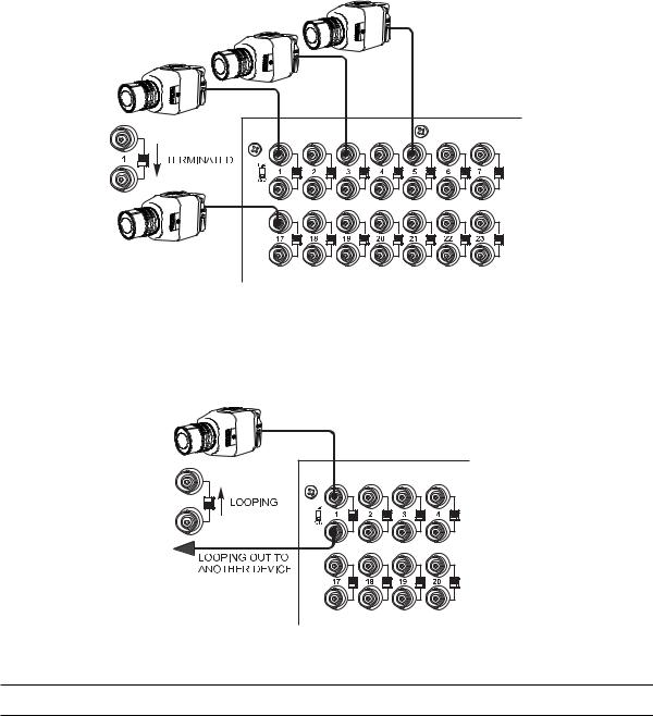
2.Set the terminating switches according to your system requirements.
Terminating switches are used to terminate or unterminate the video input. The factory default has the switches set in the terminated (75-ohm) position.
If you are connecting only a camera to an input, leave the switch in the terminated position.
00626
Figure 5. Connecting Terminated Video Sources
If you are looping the input to another device, set the rear panel switch in the unterminated (Hi-Z) position. Terminate at the final device.
00627
Figure 6. Connecting Looping Video Sources
NOTE: The end point of any video cable run must be terminated in 75 ohms.
C1522M-C (2/05) |
13 |
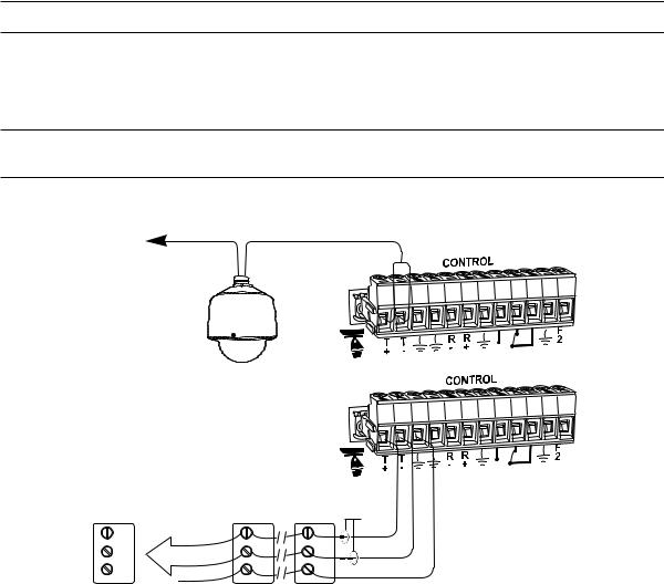
CONTROL LINES
You cannot connect a Coaxitron camera to the PTZ port. If your video sources are all controlled by Coaxitron, skip this section.
Connect camera control lines to receivers. If any of your video sources are using D or P protocol via RS-422 communications, they will connect at the PTZ connector on the back of the CM6800-32X6.
NOTE: D and P protocol receivers cannot be mixed on the same communication port but you can use D on one port and P on the other.
Daisy-chaining (going from one receiver to another) is recommended but not always possible. A maximum of 16 receivers can be daisychained from the PTZ port. If more than 16 receivers are required for your system, or if you do not want to daisy-chain the receiver connections, use the CM9760-CDU-T. You can connect up to two CM9760-CDU-T units to the CM6800-32X6.
NOTE: After completing system installation and power-up, you must configure the CM6800 and the camera/receiver. Refer to the System Start-Up section.
VIDEO TO
SWITCHER
 SHIELDED
TWISTED
PAIR
OR
RECEIVER 16 |
RECEIVER 2 |
RECEIVER 1 |
RS-422 |
|
|
|
|
R+ |
R+ |
R+ |
|
R- |
R- |
R- |
|
GND |
GND |
GND |
|
Figure 7. PTZ Control Connections
14 |
C1522M-C (2/05) |
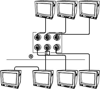
MONITORS
The CM6800-32X6 supports six monitors.
1.Install monitors according to the instructions provided with them.
2.Connect the monitor cables at the appropriate video output BNC receptacles on the back of the CM6800.
3.Terminate cables at the monitors. If you are looping to other devices, unterminate all but the last device.
MONITOR |
MONITOR |
MONITOR |
1 |
2 |
3 |
1 |
2 |
3 |
4 |
5 |
6 |
LOOPING
MONITOR |
MONITOR |
MONITOR |
MONITOR |
4B |
4A |
5 |
6 |
Figure 8. Connecting Monitors
C1522M-C (2/05) |
15 |
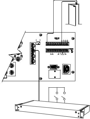
ALARMS
The CM6800 provides numerous alarm handling options. Refer to the Programming section for a detailed description.
1.Connect wires from the sensors to the respective alarm input points on the connectors at the back of the CM6800. Each sensor requires two wires – one wire to the alarm input terminal and a return wire to one of the ground terminals on the connector. The CM6800 supports eight internal alarms.
Alarm sensors can be either N.O. (normally open) or N.C. (normally closed) contacts. The CM6800 is set to N.O. as a factory default.
2.If your system requires more than eight alarms, connect an ALM2064 unit to the system. Refer to the M Devices section.
010101
2 |
3
4
5
|
|
CONTROL |
|
T |
T |
R R |
2 |
+ |
- |
- + |
COM 1
120/230V~ 50/60 HZ 25 WATTS
CM6800-32X6
ALM2064
Figure 9. Connecting Alarms
16 |
C1522M-C (2/05) |
CONNECTING DEVICES THROUGH THE COMMUNICATION PORTS
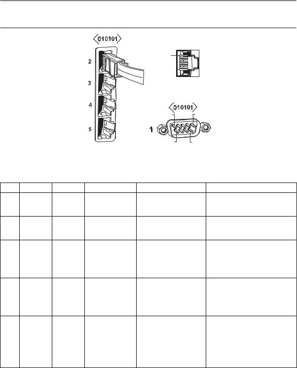
The CM6800-32X6 Matrix Switcher/Controller provides five communication ports on the rear panel for connecting peripheral components. Instructions are provided in this section for the most commonly used connections.
NOTE: Connection instructions for other periperal devices, such as the CM9760-MDA or CM9760-CDU-T, are provided as Pelco Technical Tips. Connection instructions for compatible products, such as PelcoNet transmission systems and the VMX300 are provided in the appropriate product installation manual.
PIN 1 |
PIN 8 |
|
|
|
|
|
PIN 1 |
PIN 5 |
|
|
|
|
|
|
PIN 6 |
PIN 9 |
|
|
|
|
|
Figure 10. Communication Port Inputs |
|
||
|
|
|
Table B. Communication Port Devices and Wiring |
|
|||
Port |
Input Type |
Wiring |
Pin-Outs |
Default Device |
|
Programmable to Other Device(s) |
|
1 |
DB9 |
RS-232 |
2 |
Rx |
PC Setup – CM6800MGR |
ASCII device |
|
|
|
|
3 |
Tx |
program |
|
|
|
|
|
5 |
Ground |
|
|
|
2 |
RJ-45 |
RS-232 |
1 |
Rx |
ASCII device |
|
No |
|
|
|
5 |
Ground |
|
|
|
|
|
|
8 |
Tx |
|
|
|
3 |
RJ-45 |
RS-485 |
1 |
Rx+ |
M devices – ALM2064, |
|
No |
|
|
|
2 |
Rx- |
REL2064, KBD960 |
|
|
|
|
|
5 |
Ground |
|
|
|
|
|
|
7 |
Tx- |
|
|
|
|
|
|
8 |
Tx+ |
|
|
|
4 |
RJ-45 |
RS-485 |
1 |
Rx+ |
Genex multiplexer |
|
CM9760-MDA, ASCII, keyboards |
|
|
|
2 |
Rx- |
|
|
(KBD100, 200A, & 300A) |
|
|
|
5 |
Ground |
|
|
|
|
|
|
7 |
Tx- |
|
|
|
|
|
|
8 |
Tx+ |
|
|
|
5 |
RJ-45 |
RS-485 |
1 |
Rx+ |
Keyboard (direct powered) – |
No |
|
|
|
plus power |
2 |
Rx- |
KBD100, 200, & 300 |
|
|
|
|
|
3 |
KBD power (12V) |
|
|
|
|
|
|
4 |
KBD Ground |
|
|
|
|
|
|
5 |
Ground |
|
|
|
|
|
|
7 |
Tx- |
|
|
|
|
|
|
8 |
Tx+ |
|
|
|
C1522M-C (2/05) |
17 |

|
Table C. Default Port Settings |
|
|
Port |
Default Settings |
|
|
COM 1 |
MGR, RS-232, 56000 baud, no parity, 8 data bits, 1 stop bit |
|
|
COM 2 |
ASCII, RS-232, 9600 baud, no parity, 8 data bits, 1 stop bit |
|
|
COM 3 |
M, RS-485, 19200 baud, no parity, 8 data bits, 1 stop bit |
|
|
COM 4 |
MUX-GENEX, RS-485, 9600 baud, odd parity, 8 data bits, 1 stop bit |
|
|
COM 5 |
KBD-300A, RS-485, 9600 baud, odd parity, 8 data bits, 1 stop bit |
|
|
NOTE: Refer to the Programming section for instructions on changing Port settings.
COM 3
M DEVICES (RS-485)
MAX # OF DEVICES = 6
MAXIMUM DISTANCE FROM CM6800 = 3,940 FT (1,200 M)
USING 24 AWG COPPER, UNSHIELDED TWISTED PAIR; 16 pF PER FT (pF =PICOFARADS)
4 |
5 |
4 |
5 |
4 |
5 |
4 |
5 |
4 |
5 |
4 |
5 |
4 |
5 |
3 |
6 |
3 |
6 |
3 |
6 |
3 |
6 |
3 |
6 |
3 |
6 |
3 |
6 |
2 |
7 |
2 |
7 |
2 |
7 |
2 |
7 |
2 |
7 |
2 |
7 |
2 |
7 |
1 |
8 |
1 |
8 |
1 |
8 |
1 |
8 |
1 |
8 |
1 |
8 |
1 |
8 |
STRAIGHT
CABLES
ALM2064 |
CM9505UPS |
POWER |
|
NUMBER SUPPORTED = 2 |
SUPPLY |
64 ALARMS X 2 = 128 ALARMS |
|
KBD960
REL2064 |
|
|
|
|
|
|
|
|
|
NUMBER SUPPORTED = 2 |
|
|
|
|
|
|
|
|
|
64 RELAYS X 2 = 128 |
KBD960 |
|
|
|
|
|
|
|
|
|
NUMBER SUPPORTED = 2 |
||||||||
|
010101 |
1 |
2 |
3 |
4 |
5 |
6 |
7 |
8 |
|
|
||||||||
|
|
|
|
|
16 |
COM 2 |
|
|
|
|
|
(RS232) |
|
|
|
31 |
32 |
ASCII CONTROL ONLY |
|
|
|
||
|
|
|
|
|
|
ALTERNATE EQUIPMENT |
|
|
|
3 |
|
|
|
|
|
|
|
|
|
|
|
6 |
|
|
|
|
|
VIDEO |
|
4 |
5 |
4 |
5 |
4 |
5 |
3 |
6 |
3 |
6 |
3 |
6 |
2 |
7 |
2 |
7 |
2 |
7 |
1 |
8 |
1 |
8 |
1 |
8 |
2 |
|
|
|
|
|
|
CONTROL |
|
|
3 |
|
|
|
|
T |
T |
R |
R |
2 |
+ |
- |
- |
+ |
|
4 |
|
|
|
|
5 |
|
|
|
|
|
|
COM 1 |
|
|
120/230V~ 50/60 HZ 25 WATTS
|
COM 4 |
|
|
|
ALTERNATE |
RS-232 NULL |
|
12 V 50 Hz |
OPTION |
||
MODEM CABLE |
|||
|
|||
TRANSFORMER |
|
||
|
|
COM 5
LOCAL KEYBOARDS (RS-485) KBD100/200A/300A SERIES MAX # OF DEVICES = 8
NOTE: TOTAL NUMBER OF KBD100/200A/300A SERIES KEYBOARDS CONNECTED
TO THE CM6800-32X6 CANNOT EXCEED 8
COM 1 PC SETUP (RS-232)
COM 4
GENEX (RS-485)
ALSO PROGRAMMABLE FOR KBD 100/200/300 SERIES,
CM9760-MDA, OR ASCII. MAX # OF DEVICES = 8
Figure 11. CM6800-32X6 Communication Port Connections and Options
18 |
C1522M-C (2/05) |
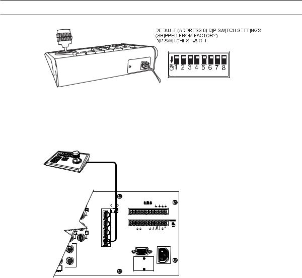
KBD100, KBD200A, AND KBD300A SERIES KEYBOARDS
You can connect up to eight KBD100/200A/300A Series keyboards to either of the following ports:
•COM 4 (up to 8 remotely connected keyboards)
•COM 5 (1 direct-powered keyboard or up to 8 remotely connected keyboards)
The total number of KBD100/200A/300A Series keyboards connected to the CM6800-32X6 cannot exceed eight.
KBD100, KBD200A, AND KBD300A: DIRECT-POWERED KEYBOARD
Use COM 5 (Serial Port 5) for a direct-powered local keyboard. COM 5 can power one KBD100/200A/300A Series keyboard.
If you are connecting more than one keyboard to COM 5, a KBDKIT(-X) is required for each keyboard. Refer to the KBD100, KBD200A, and KBD300A: Remote Keyboards section.
1.Using the 25-foot (7.62 m) straight data cable supplied with the keyboard, plug one end into the RJ-45 connector on the rear of the keyboard.
NOTE: If distance between CM6800 and keyboard exceeds 25 feet, use KBDKIT(-X).
KBD300A
Figure 12. Data Cable Plugged into Local Keyboard
2.Plug the other end of the data cable into COM 5 on the CM6800-32X6.
THE CM6800-32X6 CAN POWER ONE KBD 100/200A/300A SERIES KEYBOARD ON COM 5.
KBD100, KBD200A, KBD300A
010101
2 |
3
4
5
1 |
2 |
3 |
4 |
5 |
6 |
7 |
8 |
|
|
|
|
CONTROL |
|||
T |
T |
|
|
R R |
|
2 |
|
+ |
- |
|
|
- |
+ |
|
|
COM 1
CM6800-32X6 COM 5 |
KBD100, 200A, 300A |
||||||||
RJ-45 PIN-OUTS |
RJ-45 PIN-OUTS |
||||||||
1 |
Rx+ |
|
|
|
|
|
1 |
Tx+ |
|
|
|
|
|
|
|||||
2 |
Rx- |
|
|
|
2 |
Tx- |
|||
|
|
|
|||||||
3 |
KBD 12V |
3 |
12V |
||||||
4 |
KBD GROUND |
4 |
12V |
||||||
5 |
GROUND |
|
|
5 |
GROUND |
||||
|
|
||||||||
6 |
NC |
6 |
NC |
||||||
7 |
Tx- |
|
|
|
7 |
Rx- |
|||
|
|
|
|||||||
8 |
Tx+ |
|
|
8 |
Rx+ |
||||
|
|
||||||||
120/230V~ 50/60 HZ 25 WATTS
Figure 13. Data Cable Plugged into COM 5
C1522M-C (2/05) |
19 |
3.Set the keyboard DIP switches for the desired address for the local keyboard (refer to Figure 12 and Table D).
Table D. Keyboard Addresses: KBD100/200A/300A Series Keyboards
|
|
|
|
|
|
|
|
Switch Settings |
|
|
|||
|
|
|
|
|
|
|
|
|
|
|
|
|
|
Keyboard |
Address |
|
1 |
|
2 |
|
3 |
|
4 |
|
|||
|
|
|
|
|
|
|
|
|
|
|
|
|
|
1 |
|
0 |
|
|
OFF |
|
OFF |
|
OFF |
OFF |
|||
|
|
|
|
|
|
|
|
|
|
|
|
|
|
2 |
|
1 |
|
|
ON |
|
OFF |
|
OFF |
OFF |
|||
|
|
|
|
|
|
|
|
|
|
|
|
|
|
3 |
|
2 |
|
|
OFF |
|
ON |
|
OFF |
OFF |
|||
|
|
|
|
|
|
|
|
|
|
|
|
|
|
4 |
|
3 |
|
|
ON |
|
ON |
|
OFF |
OFF |
|||
|
|
|
|
|
|
|
|
|
|
|
|
|
|
5 |
|
4 |
|
|
OFF |
|
OFF |
|
ON |
OFF |
|||
|
|
|
|
|
|
|
|
|
|
|
|
|
|
6 |
|
5 |
|
|
ON |
|
OFF |
|
ON |
OFF |
|||
|
|
|
|
|
|
|
|
|
|
|
|
|
|
7 |
|
6 |
|
|
OFF |
|
ON |
|
ON |
OFF |
|||
|
|
|
|
|
|
|
|
|
|
|
|
|
|
8 |
|
7 |
|
|
ON |
|
ON |
|
ON |
OFF |
|||
|
|
|
|
|
|
|
|
|
|
|
|
||
|
Table E. Switch Settings – KBD200A/300A Keyboards Only |
||||||||||||
|
|
|
|
|
|
|
|
|
|
|
|
|
|
|
|
|
|
|
|
|
|
|
Switch |
|
|
||
|
Keyboard |
5 |
|
6 |
|
|
7 |
|
8 |
|
|||
|
|
|
|
|
|
|
|
|
|
|
|
|
|
|
KBD200A |
OFF |
|
|
OFF |
OFF (NOT USED) |
|
OFF |
|
||||
|
|
|
|
|
|
|
|
|
|
|
|
|
|
|
KBD300A |
OFF |
|
|
ON or OFF* |
OFF (NOT USED) |
|
OFF |
|
||||
|
|
|
|
|
|
|
|
|
|
|
|
|
|
* Switch 6 enables/disables turbo pan (can be switched while keyboard is on).
20 |
C1522M-C (2/05) |
KBD100, KBD200A, AND KBD300A: REMOTE KEYBOARDS
Use COM 4 or 5 for remote keyboard connections. Each port can support up to eight KBD100/200A/300A Series keyboards. Do not exceed a total capacity of eight keyboards connected to the CM6800-32X6.
NOTE: A KBDKIT or KBDKIT-X is required to connect remote keyboards. The KBDKIT(-X) consists of two RJ-45 wall blocks and one transformer. Use one wall block for each keyboard.
If using COM 4, you will need to change the settings (the default setting is for a Genex Multiplexer). Refer to the Programming section for instructions.
1.Select a suitable location for each keyboard and wall block. Wall blocks must be within 6 feet (1.8 m) of a suitable electrical outlet. Do not mount the wall blocks yet.
2.Connect each keyboard to a wall block, using the data cable supplied with the keyboard.
3.Remove the wall block covers and wire the connections between each wall block. Connect to a final wall block (which will be connected to the CM6800).
Communication to the keyboards is RS-485. Pelco recommends using shielded twisted pairs cable that meets or exceeds the basic requirements for EIA RS-485 applications.
4.At each wall block, wire the KBDKIT(-X) transformer to pins 3 and 4. Polarity is unimportant.
5.Replace the cover on the wall block. Secure the wall block to a suitable surface. A double-sided sticky pad is provided to mount the wall block.
6.Set the address switches for each keyboard according to Table D.
7.Connect the final wall block to COM 4 or 5 on the CM6800-32X6, using a straight data cable (supplied with the CM6800).
010101
1 2 3 4 5 6 7 8 


2 |
PT Z |
CO NT RO L |
3 |
|
|
|
|
T |
T |
R |
R |
2 |
+ |
- |
- |
+ |
|
4 |
|
|
|
|
5 |
|
|
|
|
|
|
CO M 1 |
|
|
120/230V~ 50/60 HZ 25 WATT S
CM6800-32X6 COM 5 |
KBD100, 200A, 300A |
|||||
RJ-45 PIN-OUTS |
RJ-45 PIN-OUTS |
|||||
1 |
Rx+ |
|
|
1 |
Tx+ |
|
|
|
|||||
2 |
Rx- |
|
|
2 |
Tx- |
|
|
|
|||||
3 |
KBD 12V |
3 |
NC |
|||
4 |
KBD GROUND |
4 |
NC |
|||
5 |
GROUND |
|
5 |
GROUND |
||
|
||||||
6 |
NC |
6 |
NC |
|||
7 |
Tx- |
|
7 |
Rx- |
||
|
||||||
8 |
Tx+ |
|
8 |
Rx+ |
||
|
||||||
4 |
5 |
WALL BLOCK 3 |
6 |
2 |
7 |
1 |
8 |
4 |
5 |
4 |
3 |
6 |
3 |
2 |
7 |
2 |
1 |
8 |
1 |
5 |
4 |
5 |
KBDKIT(-X) |
6 |
3 |
6 |
|
7 |
2 |
7 |
|
8 |
1 |
8 |
|


 KBD300A KBD100
KBD200A REMOTE KEYBOARDS
Figure 14. Remote Keyboards
C1522M-C (2/05) |
21 |
M DEVICES
M protocol devices (KBD960/KBR960 keyboards, ALM2064 Alarm Interface Units, and REL2064 Relay Interface Units) can be connected to COM 3 on the CM6800-32X6.
If only one device is to be connected to COM 3, use the instructions for that device in the following sections.
If more than one device is to be connected to COM 3, refer to the Multiple M Devices section.
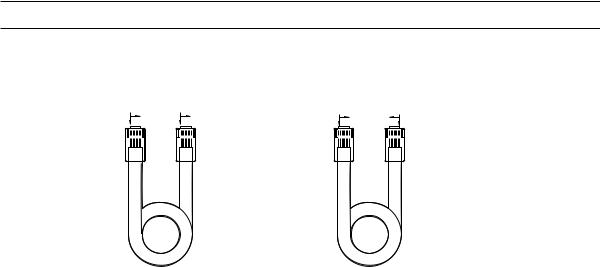
Connect M devices to the CM6800 with straight cables. Two straight cables and one reversed cable are supplied with the CM6800 (save the reversed cable for connecting a Genex Multiplexer, if applicable).
M Devices Addressing
Each M device connected to the CM6800 must have a unique local address within a range of 1-16. Use the hardware DIP switches to set the appropriate ALM2064 and REL2064 local addresses. Specify the appropriate KBD960/KBR960 local address through the keyboard Setup Mode after you complete the system installation (refer to the System Start-Up section).
For use with the CM6800, Pelco recommends numbering M devices in a sequential order. In a sample application, with two of each M device, you might assign local addresses as follows:
M device local addresses: |
Default |
Recommended for CM6800 |
KBD960/KBR960: |
1 |
1, 2 |
REL2064: |
1 |
3, 4 |
ALM2064: |
1 |
5, 6 |
NOTE: To use the CM6800 system access or keyboard priority features, you must address KBD960/KBR960 keyboards within a range of 1-8.
COMPARED "COLOR RUN" |
COMPARED "COLOR RUN" |
|
IS IN SAME DIRECTION |
IS IN OPPOSITE DIRECTION |
|
BROWN BROWN |
BROWN |
BROWN |
|
||
STRAIGHT CABLE |
|
REVERSED CABLE |
Figure 15. RJ-45 Cable Types
22 |
C1522M-C (2/05) |
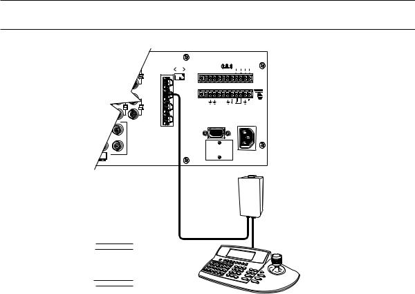
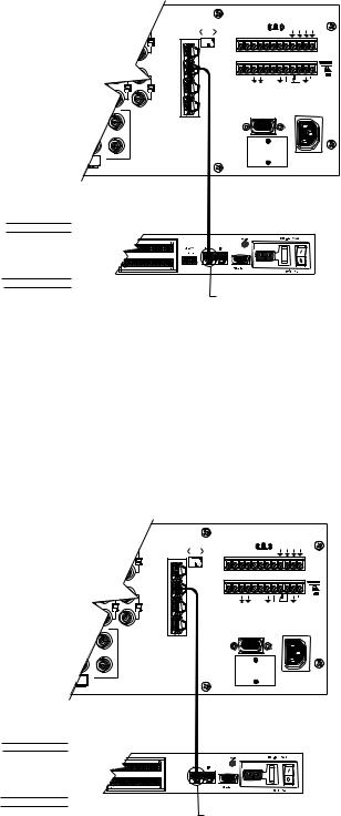
Connecting a Single KBD960/KBR960 Keyboard
To connect a single KBD960/KBR960 Keyboard to the CM6800:
1.Connect the keyboard to the CM9505UPS using the straight cable supplied with the keyboard.
2.Connect the CM9505UPS to COM 3 on the CM6800-32X6 using the 6-foot (1.8 m) straight data cable supplied with the CM6800.
NOTE: After completing system installation and power-up, you must configure the KBD960/KBR960 settings. Refer to the System Start-Up section.
010101
1 2 3 4 5 6 7 8 


2 |
CONTROL
|
|
|
3 |
|
|
|
|
|
|
|
|
T |
T |
R |
R |
2 |
COM 3 DEFAULT SETTINGS: |
|
|
|
+ |
- |
- |
+ |
||
|
|
|
4 |
|
|
|
|
M, RS-485, 19200 BAUD, |
|
|
|
|
|
|
|
|
|
|
|
|
5 |
|
|
|
|
NO PARITY, 8 DATA BITS, |
|
|
|
|
|
|
|
1 STOP BIT |
|
|
|
|
|
|
COM 1 |
|
|
|
|
|
|
|
|
|
|
|
|
|
|
|
|
|
|
|
120/230V~ |
|
|
|
|
|
|
|
|
50/60 HZ |
|
|
|
|
|
|
|
|
25 WATTS |
|
|
|
CABLE CAN BE |
|
|
|
|
|
|
|
|
STRAIGHT (SUPPLIED) |
|
|
|
|
|
|
|
|
OR REVERSED |
|
|
|
|
|
|
|
|
|
|
|
|
|
|
CM9505UPS |
|
|
|
RS-485 |
|
|
|
|
|
CM6800-32X6 COM 3 |
KBD960 |
|
|
|
|
STRAIGHT CABLE |
||
RJ-45 PIN-OUTS |
RJ-45 PIN-OUTS |
|
|
|
|
(SUPPLIED) |
||
1 |
Rx+ |
1 |
Tx+ |
|
|
|
|
|
2 |
Rx- |
2 |
Tx- |
|
|
|
|
|
3 |
NC |
3 |
|
|
|
|
|
|
4 |
NC |
4 |
|
|
|
|
|
|
5 |
GROUND |
5 |
|
|
|
|
|
|
6 |
NC |
6 |
|
|
|
|
|
|
7 |
Tx- |
7 |
Rx- |
|
|
|
|
|
8 |
Tx+ |
8 |
Rx+ |
|
|
|
|
|
|
|
|
KBD960 |
|
|
|||
Figure 16. Connecting a KBD960/KBR960 to the CM6800-32X6
C1522M-C (2/05) |
23 |
Connecting a Single ALM2064 Alarm Interface Unit
To connect a single ALM2064 Alarm Interface Unit:
1.Connect the ALM2064 OUT port to COM 3 on the CM6800-32X6 using the 6-foot (1.8 m) straight data cable supplied with the CM6800.
2.Set SW2, DIP switches 1-8 to the appropriate positions for the local address (default address setting is 1). Refer to the ALM2064 Alarm Interface Unit Installation/Operation Manual for instructions.
010101
2 |
3
4
5
1 |
2 |
3 |
4 |
5 |
6 |
7 |
8 |
|
|
|
|
CONTROL |
|||
T |
T |
|
|
R |
R |
|
2 |
+ |
- |
|
|
- |
+ |
|
|
COM 3 DEFAULT SETTINGS: M, RS-485, 19200 BAUD, NO PARITY, 8 DATA BITS,
1 STOP BIT
COM 1
120/230V~ 50/60 HZ 25 WATTS
CM6800 -32X6 COM 3 |
ALM2064 |
|
STRAIGHT CABLE |
||
|
(SUPPLIED) |
||||
RJ-45 PIN-OUTS |
RJ-45 PIN-OUTS |
|
|||
|
|
||||
1 |
Rx+ |
1 |
Tx+ |
ALM2064 |
RS-485 |
2 |
Rx- |
2 |
Tx- |
|
|
|
|
||||
3 |
NC |
3 |
|
|
|
4 |
NC |
4 |
|
|
|
5 |
GROUND |
5 |
|
|
|
6 |
NC |
6 |
|
|
|
7 |
Tx- |
7 |
Rx- |
|
|
8 |
Tx+ |
8 |
Rx+ |
|
|
CONNECT THROUGH
THE "OUT" PORT
Figure 17. Connecting a Single ALM2064 Alarm Interface Unit
Connecting a Single REL2064 Relay Interface Unit
To connect a single REL2064 Relay Interface Unit:
1.Connect the REL2064 OUT port to COM 3 on the CM6800-32X6 using the 6-foot (1.8 m) straight data cable supplied with the CM6800.
2.Set SW2, DIP switches 1-8 to the appropriate positions for the local address (default address setting is 1). Refer to the REL2064 Relay Interface Unit Installation/Operation Manual for instructions.
010101
2 |
3
4
5
1 |
2 |
3 |
4 |
5 |
6 |
7 |
8 |
|
|
|
|
CONTROL |
|||
T |
T |
|
|
R |
R |
|
2 |
+ |
- |
|
|
- |
+ |
|
|
COM 1
COM 3 DEFAULT SETTINGS: M, RS-485, 19200 BAUD, NO PARITY, 8 DATA BITS,
1 STOP BIT
120/230V~ 50/60 HZ 25 WATTS
CM6800-32X6 COM 3 |
REL2064 |
STRAIGHT CABLE |
|||
RJ-45 PIN-OUTS |
RJ-45 PIN-OUTS |
(SUPPLIED) |
|||
1 |
Rx+ |
1 |
Tx+ |
REL2064 |
|
2 |
Rx- |
2 |
Tx- |
||
|
|||||
3 |
NC |
3 |
|
|
|
4 |
NC |
4 |
|
|
|
5 |
GROUND |
5 |
|
|
|
6 |
NC |
6 |
|
|
|
7 |
Tx- |
7 |
Rx- |
|
|
8 |
Tx+ |
8 |
Rx+ |
|
|
CONNECT THROUGH
THE "OUT" PORT
Figure 18. Connecting a Single REL2064 Relay Interface Unit
24 |
C1522M-C (2/05) |
 Loading...