


 Loading...
Installation Manual
DX8000 |
Digital Video Recorder |
C623M-C (3/05) |
|
|
|
|
|
|

Protecting people and property in a million locations worldwide.

Contents
Before You Begin . . . . . . . . . . . . . . . . . . . . . . . . . . . . . . . . . . . . . . . . . . . . . . . . . . . . . . . . . . . . . . . . . . . . . . . . . . . . . . . . . . . . . . . . . . . . . . . . . . . . .7
Additional Warnings and Cautions . . . . . . . . . . . . . . . . . . . . . . . . . . . . . . . . . . . . . . . . . . . . . . . . . . . . . . . . . . . . . . . . . . . . . . . . . . . . . . . . . . . . . . . .8
Regulatory Notices . . . . . . . . . . . . . . . . . . . . . . . . . . . . . . . . . . . . . . . . . . . . . . . . . . . . . . . . . . . . . . . . . . . . . . . . . . . . . . . . . . . . . . . . . . . . . . . . . . . .9
Description . . . . . . . . . . . . . . . . . . . . . . . . . . . . . . . . . . . . . . . . . . . . . . . . . . . . . . . . . . . . . . . . . . . . . . . . . . . . . . . . . . . . . . . . . . . . . . . . . . . . . . . . .10
Features . . . . . . . . . . . . . . . . . . . . . . . . . . . . . . . . . . . . . . . . . . . . . . . . . . . . . . . . . . . . . . . . . . . . . . . . . . . . . . . . . . . . . . . . . . . . . . . . . . . . . . .11
Models . . . . . . . . . . . . . . . . . . . . . . . . . . . . . . . . . . . . . . . . . . . . . . . . . . . . . . . . . . . . . . . . . . . . . . . . . . . . . . . . . . . . . . . . . . . . . . . . . . . . . . . .12
Optional Accessories . . . . . . . . . . . . . . . . . . . . . . . . . . . . . . . . . . . . . . . . . . . . . . . . . . . . . . . . . . . . . . . . . . . . . . . . . . . . . . . . . . . . . . . . . . . . .12
Parts List . . . . . . . . . . . . . . . . . . . . . . . . . . . . . . . . . . . . . . . . . . . . . . . . . . . . . . . . . . . . . . . . . . . . . . . . . . . . . . . . . . . . . . . . . . . . . . . . . . . . . . . . . . .13
Application Examples . . . . . . . . . . . . . . . . . . . . . . . . . . . . . . . . . . . . . . . . . . . . . . . . . . . . . . . . . . . . . . . . . . . . . . . . . . . . . . . . . . . . . . . . . . . . . . . . .14
Equipment Rack Mounting . . . . . . . . . . . . . . . . . . . . . . . . . . . . . . . . . . . . . . . . . . . . . . . . . . . . . . . . . . . . . . . . . . . . . . . . . . . . . . . . . . . . . . . . . . . . .15
Back Panel Layout . . . . . . . . . . . . . . . . . . . . . . . . . . . . . . . . . . . . . . . . . . . . . . . . . . . . . . . . . . . . . . . . . . . . . . . . . . . . . . . . . . . . . . . . . . . . . . . . . . . .17
Hardware Setup . . . . . . . . . . . . . . . . . . . . . . . . . . . . . . . . . . . . . . . . . . . . . . . . . . . . . . . . . . . . . . . . . . . . . . . . . . . . . . . . . . . . . . . . . . . . . . . . . . . . .18
Basic Connections . . . . . . . . . . . . . . . . . . . . . . . . . . . . . . . . . . . . . . . . . . . . . . . . . . . . . . . . . . . . . . . . . . . . . . . . . . . . . . . . . . . . . . . . . . . . . . .18
Network Setup . . . . . . . . . . . . . . . . . . . . . . . . . . . . . . . . . . . . . . . . . . . . . . . . . . . . . . . . . . . . . . . . . . . . . . . . . . . . . . . . . . . . . . . . . . . . . . . . . .19
RS-422/RS-485 Communication Port Setup . . . . . . . . . . . . . . . . . . . . . . . . . . . . . . . . . . . . . . . . . . . . . . . . . . . . . . . . . . . . . . . . . . . . . . . . . . .20
Alarm Input Installation . . . . . . . . . . . . . . . . . . . . . . . . . . . . . . . . . . . . . . . . . . . . . . . . . . . . . . . . . . . . . . . . . . . . . . . . . . . . . . . . . . . . . . . . . . .22
Relay Output Installation . . . . . . . . . . . . . . . . . . . . . . . . . . . . . . . . . . . . . . . . . . . . . . . . . . . . . . . . . . . . . . . . . . . . . . . . . . . . . . . . . . . . . . . . . .23
Software Setup . . . . . . . . . . . . . . . . . . . . . . . . . . . . . . . . . . . . . . . . . . . . . . . . . . . . . . . . . . . . . . . . . . . . . . . . . . . . . . . . . . . . . . . . . . . . . . . . . . . . . .24 Starting the Unit . . . . . . . . . . . . . . . . . . . . . . . . . . . . . . . . . . . . . . . . . . . . . . . . . . . . . . . . . . . . . . . . . . . . . . . . . . . . . . . . . . . . . . . . . . . . . . . .24 Logging in for the First Time . . . . . . . . . . . . . . . . . . . . . . . . . . . . . . . . . . . . . . . . . . . . . . . . . . . . . . . . . . . . . . . . . . . . . . . . . . . . . . . . . . . . . . .25 Shutting Down . . . . . . . . . . . . . . . . . . . . . . . . . . . . . . . . . . . . . . . . . . . . . . . . . . . . . . . . . . . . . . . . . . . . . . . . . . . . . . . . . . . . . . . . . . . . . . . . . .26 Exiting to Windows Operating System . . . . . . . . . . . . . . . . . . . . . . . . . . . . . . . . . . . . . . . . . . . . . . . . . . . . . . . . . . . . . . . . . . . . . . . . . . . . . . .27 Setting the System Language . . . . . . . . . . . . . . . . . . . . . . . . . . . . . . . . . . . . . . . . . . . . . . . . . . . . . . . . . . . . . . . . . . . . . . . . . . . . . . . . . . . . . .28
Configuring the Regional Setting in the Windows Operating System . . . . . . . . . . . . . . . . . . . . . . . . . . . . . . . . . . . . . . . . . . . . . . . . . . .28 Configuring the Language Setting of the DX8000 . . . . . . . . . . . . . . . . . . . . . . . . . . . . . . . . . . . . . . . . . . . . . . . . . . . . . . . . . . . . . . . . . .32 Setting the System Time . . . . . . . . . . . . . . . . . . . . . . . . . . . . . . . . . . . . . . . . . . . . . . . . . . . . . . . . . . . . . . . . . . . . . . . . . . . . . . . . . . . . . . . . . .33 Enabling and Using Ctrl+Alt+Del . . . . . . . . . . . . . . . . . . . . . . . . . . . . . . . . . . . . . . . . . . . . . . . . . . . . . . . . . . . . . . . . . . . . . . . . . . . . . . . . . . . .34 Using Ctrl+Alt+Del . . . . . . . . . . . . . . . . . . . . . . . . . . . . . . . . . . . . . . . . . . . . . . . . . . . . . . . . . . . . . . . . . . . . . . . . . . . . . . . . . . . . . . . . . .34 Network Software Configuration . . . . . . . . . . . . . . . . . . . . . . . . . . . . . . . . . . . . . . . . . . . . . . . . . . . . . . . . . . . . . . . . . . . . . . . . . . . . . . . . . . .35 DHCP Setup . . . . . . . . . . . . . . . . . . . . . . . . . . . . . . . . . . . . . . . . . . . . . . . . . . . . . . . . . . . . . . . . . . . . . . . . . . . . . . . . . . . . . . . . . . . . . . . .36 Static IP Setup . . . . . . . . . . . . . . . . . . . . . . . . . . . . . . . . . . . . . . . . . . . . . . . . . . . . . . . . . . . . . . . . . . . . . . . . . . . . . . . . . . . . . . . . . . . . .37 TCP/IP Port and Bandwidth Throttle Setup . . . . . . . . . . . . . . . . . . . . . . . . . . . . . . . . . . . . . . . . . . . . . . . . . . . . . . . . . . . . . . . . . . . . . . .38 Accessing Network Information . . . . . . . . . . . . . . . . . . . . . . . . . . . . . . . . . . . . . . . . . . . . . . . . . . . . . . . . . . . . . . . . . . . . . . . . . . . . . . . .40 DNS/WINS Setup . . . . . . . . . . . . . . . . . . . . . . . . . . . . . . . . . . . . . . . . . . . . . . . . . . . . . . . . . . . . . . . . . . . . . . . . . . . . . . . . . . . . . . . . . . .41 RS-422/RS-485 Communication Port Software Configuration . . . . . . . . . . . . . . . . . . . . . . . . . . . . . . . . . . . . . . . . . . . . . . . . . . . . . . . . . . . . .42 Client Software Setup . . . . . . . . . . . . . . . . . . . . . . . . . . . . . . . . . . . . . . . . . . . . . . . . . . . . . . . . . . . . . . . . . . . . . . . . . . . . . . . . . . . . . . . . . . . .44 Recommended System Requirements . . . . . . . . . . . . . . . . . . . . . . . . . . . . . . . . . . . . . . . . . . . . . . . . . . . . . . . . . . . . . . . . . . . . . . . . . . .44 Installing the PC Client Application . . . . . . . . . . . . . . . . . . . . . . . . . . . . . . . . . . . . . . . . . . . . . . . . . . . . . . . . . . . . . . . . . . . . . . . . . . . . .44 Enabling IPSec Security Services . . . . . . . . . . . . . . . . . . . . . . . . . . . . . . . . . . . . . . . . . . . . . . . . . . . . . . . . . . . . . . . . . . . . . . . . . . . . . . .47 Disabling IPSec Security Services . . . . . . . . . . . . . . . . . . . . . . . . . . . . . . . . . . . . . . . . . . . . . . . . . . . . . . . . . . . . . . . . . . . . . . . . . . . . . .47 Installing the Client Emergency Agent Application . . . . . . . . . . . . . . . . . . . . . . . . . . . . . . . . . . . . . . . . . . . . . . . . . . . . . . . . . . . . . . . . .48 Installing the DX8000 Viewer . . . . . . . . . . . . . . . . . . . . . . . . . . . . . . . . . . . . . . . . . . . . . . . . . . . . . . . . . . . . . . . . . . . . . . . . . . . . . . . . . .51 Installing the DX8000 Web Client . . . . . . . . . . . . . . . . . . . . . . . . . . . . . . . . . . . . . . . . . . . . . . . . . . . . . . . . . . . . . . . . . . . . . . . . . . . . . .52 Recommended System Requirements for Mobile (PDA) Client . . . . . . . . . . . . . . . . . . . . . . . . . . . . . . . . . . . . . . . . . . . . . . . . . . . . . . . .53 Installing the Mobile (PDA) Client application . . . . . . . . . . . . . . . . . . . . . . . . . . . . . . . . . . . . . . . . . . . . . . . . . . . . . . . . . . . . . . . . . . . . .54
Accessing the DX8000’s Electronic Documentation . . . . . . . . . . . . . . . . . . . . . . . . . . . . . . . . . . . . . . . . . . . . . . . . . . . . . . . . . . . . . . . . . . . . . . . . . |
56 |
Appendix A: Printer Setup . . . . . . . . . . . . . . . . . . . . . . . . . . . . . . . . . . . . . . . . . . . . . . . . . . . . . . . . . . . . . . . . . . . . . . . . . . . . . . . . . . . . . . . . . . . . . |
57 |
Printer Hardware Setup . . . . . . . . . . . . . . . . . . . . . . . . . . . . . . . . . . . . . . . . . . . . . . . . . . . . . . . . . . . . . . . . . . . . . . . . . . . . . . . . . . . . . . . . . . . |
57 |
Printer Software Setup . . . . . . . . . . . . . . . . . . . . . . . . . . . . . . . . . . . . . . . . . . . . . . . . . . . . . . . . . . . . . . . . . . . . . . . . . . . . . . . . . . . . . . . . . . . |
59 |
C623M-C (3/05) |
3 |
Setting Up a Local Plug-and-Play Printer . . . . . . . . . . . . . . . . . . . . . . . . . . . . . . . . . . . . . . . . . . . . . . . . . . . . . . . . . . . . . . . . . . . . . . . . .59 Setting Up a Local Printer that is Not Plug-and-Play . . . . . . . . . . . . . . . . . . . . . . . . . . . . . . . . . . . . . . . . . . . . . . . . . . . . . . . . . . . . . . . .62 Setting Up a Network Printer . . . . . . . . . . . . . . . . . . . . . . . . . . . . . . . . . . . . . . . . . . . . . . . . . . . . . . . . . . . . . . . . . . . . . . . . . . . . . . . . . .68
Appendix B: Connecting Optional DX8000-MUX8/16 Display Card . . . . . . . . . . . . . . . . . . . . . . . . . . . . . . . . . . . . . . . . . . . . . . . . . . . . . . . . . . . . . .72
Appendix C: Connecting the Optional DX8000-AUD Audio Option . . . . . . . . . . . . . . . . . . . . . . . . . . . . . . . . . . . . . . . . . . . . . . . . . . . . . . . . . . . . . .73 Setting Up Audio Inputs . . . . . . . . . . . . . . . . . . . . . . . . . . . . . . . . . . . . . . . . . . . . . . . . . . . . . . . . . . . . . . . . . . . . . . . . . . . . . . . . . . . . . . . . . . .73 Setting Up Audio Output . . . . . . . . . . . . . . . . . . . . . . . . . . . . . . . . . . . . . . . . . . . . . . . . . . . . . . . . . . . . . . . . . . . . . . . . . . . . . . . . . . . . . . . . . .75
Appendix D: Connecting an Uninterruptible Power Supply (UPS) . . . . . . . . . . . . . . . . . . . . . . . . . . . . . . . . . . . . . . . . . . . . . . . . . . . . . . . . . . . . . . .76 UPS to DVR Communication and Power Connections . . . . . . . . . . . . . . . . . . . . . . . . . . . . . . . . . . . . . . . . . . . . . . . . . . . . . . . . . . . . . . . . . . . .76 Software Setup for a USB Connected UPS Device . . . . . . . . . . . . . . . . . . . . . . . . . . . . . . . . . . . . . . . . . . . . . . . . . . . . . . . . . . . . . . . . . . . . . .77
Appendix E: External Storage Expansion Using DX9200HDDI . . . . . . . . . . . . . . . . . . . . . . . . . . . . . . . . . . . . . . . . . . . . . . . . . . . . . . . . . . . . . . . . . . |
80 |
Basic Installation . . . . . . . . . . . . . . . . . . . . . . . . . . . . . . . . . . . . . . . . . . . . . . . . . . . . . . . . . . . . . . . . . . . . . . . . . . . . . . . . . . . . . . . . . . . . . . . . |
80 |
Additional Hard Disk Installation . . . . . . . . . . . . . . . . . . . . . . . . . . . . . . . . . . . . . . . . . . . . . . . . . . . . . . . . . . . . . . . . . . . . . . . . . . . . . . . . . . . . |
81 |
Preparing the DX8000 to Access Newly Installed Drives . . . . . . . . . . . . . . . . . . . . . . . . . . . . . . . . . . . . . . . . . . . . . . . . . . . . . . . . . . . . |
81 |
Specifications . . . . . . . . . . . . . . . . . . . . . . . . . . . . . . . . . . . . . . . . . . . . . . . . . . . . . . . . . . . . . . . . . . . . . . . . . . . . . . . . . . . . . . . . . . . . . . . . . . . . . . . |
93 |
List of Tables
A Video Coaxial Cable Requirements . . . . . . . . . . . . . . . . . . . . . . . . . . . . . . . . . . . . . . . . . . . . . . . . . . . . . . . . . . . . . . . . . . . . . . . . . . . . . . . .18 B TCP/IP Ports Used by the DX8000 . . . . . . . . . . . . . . . . . . . . . . . . . . . . . . . . . . . . . . . . . . . . . . . . . . . . . . . . . . . . . . . . . . . . . . . . . . . . . . . . .38 C RS-422/RS-485 Port Settings. . . . . . . . . . . . . . . . . . . . . . . . . . . . . . . . . . . . . . . . . . . . . . . . . . . . . . . . . . . . . . . . . . . . . . . . . . . . . . . . . . . . .42 D DX8000 Manual Documents . . . . . . . . . . . . . . . . . . . . . . . . . . . . . . . . . . . . . . . . . . . . . . . . . . . . . . . . . . . . . . . . . . . . . . . . . . . . . . . . . . . . .56
4 |
C623M-C (3/05) |

List of Illustrations
1 System with Single DX8000. . . . . . . . . . . . . . . . . . . . . . . . . . . . . . . . . . . . . . . . . . . . . . . . . . . . . . . . . . . . . . . . . . . . . . . . . . . . . . . . . . . . . .14 2 System with Multiple DX8000s . . . . . . . . . . . . . . . . . . . . . . . . . . . . . . . . . . . . . . . . . . . . . . . . . . . . . . . . . . . . . . . . . . . . . . . . . . . . . . . . . . .14 3 System with Multiple DX8000s and Multiple Clients . . . . . . . . . . . . . . . . . . . . . . . . . . . . . . . . . . . . . . . . . . . . . . . . . . . . . . . . . . . . . . . . . .14 4 Remove Left and Right Side Plates . . . . . . . . . . . . . . . . . . . . . . . . . . . . . . . . . . . . . . . . . . . . . . . . . . . . . . . . . . . . . . . . . . . . . . . . . . . . . . . .15 5 Attaching Rack Ears and Handles . . . . . . . . . . . . . . . . . . . . . . . . . . . . . . . . . . . . . . . . . . . . . . . . . . . . . . . . . . . . . . . . . . . . . . . . . . . . . . . . .15 6 Rack Mount Installation . . . . . . . . . . . . . . . . . . . . . . . . . . . . . . . . . . . . . . . . . . . . . . . . . . . . . . . . . . . . . . . . . . . . . . . . . . . . . . . . . . . . . . . . .16 7 Back Panel Layout . . . . . . . . . . . . . . . . . . . . . . . . . . . . . . . . . . . . . . . . . . . . . . . . . . . . . . . . . . . . . . . . . . . . . . . . . . . . . . . . . . . . . . . . . . . . .17 8 Basic Connections . . . . . . . . . . . . . . . . . . . . . . . . . . . . . . . . . . . . . . . . . . . . . . . . . . . . . . . . . . . . . . . . . . . . . . . . . . . . . . . . . . . . . . . . . . . . .18 9 LAN/WAN Cable Connection . . . . . . . . . . . . . . . . . . . . . . . . . . . . . . . . . . . . . . . . . . . . . . . . . . . . . . . . . . . . . . . . . . . . . . . . . . . . . . . . . . . . .19
10 RS-422/RS-485 Configuration Example 1 . . . . . . . . . . . . . . . . . . . . . . . . . . . . . . . . . . . . . . . . . . . . . . . . . . . . . . . . . . . . . . . . . . . . . . . . . . .20 11 RS-422/RS-485 Configuration Example 2 . . . . . . . . . . . . . . . . . . . . . . . . . . . . . . . . . . . . . . . . . . . . . . . . . . . . . . . . . . . . . . . . . . . . . . . . . . .21 12 Cable Wiring Schemes. . . . . . . . . . . . . . . . . . . . . . . . . . . . . . . . . . . . . . . . . . . . . . . . . . . . . . . . . . . . . . . . . . . . . . . . . . . . . . . . . . . . . . . . . .21 13 Alarm Terminal Installation . . . . . . . . . . . . . . . . . . . . . . . . . . . . . . . . . . . . . . . . . . . . . . . . . . . . . . . . . . . . . . . . . . . . . . . . . . . . . . . . . . . . . .22 14 Relay Terminal Installation. . . . . . . . . . . . . . . . . . . . . . . . . . . . . . . . . . . . . . . . . . . . . . . . . . . . . . . . . . . . . . . . . . . . . . . . . . . . . . . . . . . . . . .23 15 Front Panel and Power Switch . . . . . . . . . . . . . . . . . . . . . . . . . . . . . . . . . . . . . . . . . . . . . . . . . . . . . . . . . . . . . . . . . . . . . . . . . . . . . . . . . . . .24 16 User Log-in Dialog Box. . . . . . . . . . . . . . . . . . . . . . . . . . . . . . . . . . . . . . . . . . . . . . . . . . . . . . . . . . . . . . . . . . . . . . . . . . . . . . . . . . . . . . . . . .25 17 Set Admin Password Dialog Box . . . . . . . . . . . . . . . . . . . . . . . . . . . . . . . . . . . . . . . . . . . . . . . . . . . . . . . . . . . . . . . . . . . . . . . . . . . . . . . . . .26 18 Shut Down Dialog Box . . . . . . . . . . . . . . . . . . . . . . . . . . . . . . . . . . . . . . . . . . . . . . . . . . . . . . . . . . . . . . . . . . . . . . . . . . . . . . . . . . . . . . . . . .26 19 Shut Down Dialog Box . . . . . . . . . . . . . . . . . . . . . . . . . . . . . . . . . . . . . . . . . . . . . . . . . . . . . . . . . . . . . . . . . . . . . . . . . . . . . . . . . . . . . . . . . .27 20 Control Panel with Regional Options Selected . . . . . . . . . . . . . . . . . . . . . . . . . . . . . . . . . . . . . . . . . . . . . . . . . . . . . . . . . . . . . . . . . . . . . . .28 21 Regional Options Dialog Box . . . . . . . . . . . . . . . . . . . . . . . . . . . . . . . . . . . . . . . . . . . . . . . . . . . . . . . . . . . . . . . . . . . . . . . . . . . . . . . . . . . . .29 22 Select System Locale Dialog Box. . . . . . . . . . . . . . . . . . . . . . . . . . . . . . . . . . . . . . . . . . . . . . . . . . . . . . . . . . . . . . . . . . . . . . . . . . . . . . . . . .30 23 Regional Options Dialog Box . . . . . . . . . . . . . . . . . . . . . . . . . . . . . . . . . . . . . . . . . . . . . . . . . . . . . . . . . . . . . . . . . . . . . . . . . . . . . . . . . . . . .30 24 General Dialog Box. . . . . . . . . . . . . . . . . . . . . . . . . . . . . . . . . . . . . . . . . . . . . . . . . . . . . . . . . . . . . . . . . . . . . . . . . . . . . . . . . . . . . . . . . . . . .31 25 Change Regional Options Dialog Box . . . . . . . . . . . . . . . . . . . . . . . . . . . . . . . . . . . . . . . . . . . . . . . . . . . . . . . . . . . . . . . . . . . . . . . . . . . . . .31 26 System Page: Selecting the Language. . . . . . . . . . . . . . . . . . . . . . . . . . . . . . . . . . . . . . . . . . . . . . . . . . . . . . . . . . . . . . . . . . . . . . . . . . . . . .32 27 Setting the System Time . . . . . . . . . . . . . . . . . . . . . . . . . . . . . . . . . . . . . . . . . . . . . . . . . . . . . . . . . . . . . . . . . . . . . . . . . . . . . . . . . . . . . . . .33 28 Network Setup Page: Software Configuration. . . . . . . . . . . . . . . . . . . . . . . . . . . . . . . . . . . . . . . . . . . . . . . . . . . . . . . . . . . . . . . . . . . . . . . .35 29 DHCP Setup . . . . . . . . . . . . . . . . . . . . . . . . . . . . . . . . . . . . . . . . . . . . . . . . . . . . . . . . . . . . . . . . . . . . . . . . . . . . . . . . . . . . . . . . . . . . . . . . . .36 30 Static IP Setup . . . . . . . . . . . . . . . . . . . . . . . . . . . . . . . . . . . . . . . . . . . . . . . . . . . . . . . . . . . . . . . . . . . . . . . . . . . . . . . . . . . . . . . . . . . . . . . .37 31 Base Port and Bandwidth Throttle Setup. . . . . . . . . . . . . . . . . . . . . . . . . . . . . . . . . . . . . . . . . . . . . . . . . . . . . . . . . . . . . . . . . . . . . . . . . . . .39 32 IP Configuration Status Box . . . . . . . . . . . . . . . . . . . . . . . . . . . . . . . . . . . . . . . . . . . . . . . . . . . . . . . . . . . . . . . . . . . . . . . . . . . . . . . . . . . . . .40 33 DNS/WINS Setup. . . . . . . . . . . . . . . . . . . . . . . . . . . . . . . . . . . . . . . . . . . . . . . . . . . . . . . . . . . . . . . . . . . . . . . . . . . . . . . . . . . . . . . . . . . . . .41 34 RS-422/RS-485 Port Setup Page . . . . . . . . . . . . . . . . . . . . . . . . . . . . . . . . . . . . . . . . . . . . . . . . . . . . . . . . . . . . . . . . . . . . . . . . . . . . . . . . . .43 35 Resource CD Screen: PC Client Installation Option . . . . . . . . . . . . . . . . . . . . . . . . . . . . . . . . . . . . . . . . . . . . . . . . . . . . . . . . . . . . . . . . . . . .44 36 DX8000 Security Setup Dialog Box . . . . . . . . . . . . . . . . . . . . . . . . . . . . . . . . . . . . . . . . . . . . . . . . . . . . . . . . . . . . . . . . . . . . . . . . . . . . . . . .44 37 DX8000 Client Setup Dialog Box . . . . . . . . . . . . . . . . . . . . . . . . . . . . . . . . . . . . . . . . . . . . . . . . . . . . . . . . . . . . . . . . . . . . . . . . . . . . . . . . . .45 38 Software License Agreement Dialog Box . . . . . . . . . . . . . . . . . . . . . . . . . . . . . . . . . . . . . . . . . . . . . . . . . . . . . . . . . . . . . . . . . . . . . . . . . . .45 39 Select Installation Folder Dialog Box. . . . . . . . . . . . . . . . . . . . . . . . . . . . . . . . . . . . . . . . . . . . . . . . . . . . . . . . . . . . . . . . . . . . . . . . . . . . . . .46 40 Installation is Completed Successfully Dialog Box . . . . . . . . . . . . . . . . . . . . . . . . . . . . . . . . . . . . . . . . . . . . . . . . . . . . . . . . . . . . . . . . . . . .46 41 Enabling IPSec Security for the PC Client Application. . . . . . . . . . . . . . . . . . . . . . . . . . . . . . . . . . . . . . . . . . . . . . . . . . . . . . . . . . . . . . . . . .47 42 Enabling IPSec Security for the PC Client Application. . . . . . . . . . . . . . . . . . . . . . . . . . . . . . . . . . . . . . . . . . . . . . . . . . . . . . . . . . . . . . . . . .47 43 Resource CD Screen: Emergency Agent Installation Option . . . . . . . . . . . . . . . . . . . . . . . . . . . . . . . . . . . . . . . . . . . . . . . . . . . . . . . . . . . . .48 44 DX8000 Security Setup Dialog Box . . . . . . . . . . . . . . . . . . . . . . . . . . . . . . . . . . . . . . . . . . . . . . . . . . . . . . . . . . . . . . . . . . . . . . . . . . . . . . . .48 45 DX8000 Emergency Agent Setup Program Dialog Box . . . . . . . . . . . . . . . . . . . . . . . . . . . . . . . . . . . . . . . . . . . . . . . . . . . . . . . . . . . . . . . . .49 46 Emergency Agent Software License Agreement Dialog Box. . . . . . . . . . . . . . . . . . . . . . . . . . . . . . . . . . . . . . . . . . . . . . . . . . . . . . . . . . . . .49 47 Select Installation Folder Dialog Box. . . . . . . . . . . . . . . . . . . . . . . . . . . . . . . . . . . . . . . . . . . . . . . . . . . . . . . . . . . . . . . . . . . . . . . . . . . . . . .50 48 Installation is Completed Successfully Dialog Box . . . . . . . . . . . . . . . . . . . . . . . . . . . . . . . . . . . . . . . . . . . . . . . . . . . . . . . . . . . . . . . . . . . .50 49 Resource CD Window: Native Viewer Option . . . . . . . . . . . . . . . . . . . . . . . . . . . . . . . . . . . . . . . . . . . . . . . . . . . . . . . . . . . . . . . . . . . . . . . .51 50 Enter Network Password Dialog Box . . . . . . . . . . . . . . . . . . . . . . . . . . . . . . . . . . . . . . . . . . . . . . . . . . . . . . . . . . . . . . . . . . . . . . . . . . . . . . .52 51 Security Warning Dialog Box: ActiveX Control Installation. . . . . . . . . . . . . . . . . . . . . . . . . . . . . . . . . . . . . . . . . . . . . . . . . . . . . . . . . . . . . .53 52 PDA to PC Connection . . . . . . . . . . . . . . . . . . . . . . . . . . . . . . . . . . . . . . . . . . . . . . . . . . . . . . . . . . . . . . . . . . . . . . . . . . . . . . . . . . . . . . . . . .54 53 Resource CD Window: Mobile Client Installation Option . . . . . . . . . . . . . . . . . . . . . . . . . . . . . . . . . . . . . . . . . . . . . . . . . . . . . . . . . . . . . . .54 54 Pocket PC Installation Dialog Box . . . . . . . . . . . . . . . . . . . . . . . . . . . . . . . . . . . . . . . . . . . . . . . . . . . . . . . . . . . . . . . . . . . . . . . . . . . . . . . . .54 55 License Agreement Dialog Box . . . . . . . . . . . . . . . . . . . . . . . . . . . . . . . . . . . . . . . . . . . . . . . . . . . . . . . . . . . . . . . . . . . . . . . . . . . . . . . . . . .55 56 Installing Applications Dialog Box . . . . . . . . . . . . . . . . . . . . . . . . . . . . . . . . . . . . . . . . . . . . . . . . . . . . . . . . . . . . . . . . . . . . . . . . . . . . . . . . .55 57 Application Downloading Complete Dialog Box . . . . . . . . . . . . . . . . . . . . . . . . . . . . . . . . . . . . . . . . . . . . . . . . . . . . . . . . . . . . . . . . . . . . . .55 58 Resource CD Window: PC Client Installation Option. . . . . . . . . . . . . . . . . . . . . . . . . . . . . . . . . . . . . . . . . . . . . . . . . . . . . . . . . . . . . . . . . . .56 59 Printer Connection . . . . . . . . . . . . . . . . . . . . . . . . . . . . . . . . . . . . . . . . . . . . . . . . . . . . . . . . . . . . . . . . . . . . . . . . . . . . . . . . . . . . . . . . . . . . .58 60 Printer Setup Window (Plug-and-Play). . . . . . . . . . . . . . . . . . . . . . . . . . . . . . . . . . . . . . . . . . . . . . . . . . . . . . . . . . . . . . . . . . . . . . . . . . . . . .59
C623M-C (3/05) |
5 |
61 Add Printer Wizard Dialog Box (Plug-and-Play) . . . . . . . . . . . . . . . . . . . . . . . . . . . . . . . . . . . . . . . . . . . . . . . . . . . . . . . . . . . . . . . . . . . . . . .60 62 Local or Network Printer Dialog Box (Plug-and-Play). . . . . . . . . . . . . . . . . . . . . . . . . . . . . . . . . . . . . . . . . . . . . . . . . . . . . . . . . . . . . . . . . . .60 63 Finding and Initializing a Plug-and-Play Printer . . . . . . . . . . . . . . . . . . . . . . . . . . . . . . . . . . . . . . . . . . . . . . . . . . . . . . . . . . . . . . . . . . . . . . .61 64 Completing the Add Printer Wizard Dialog Box (Plug-and-Play) . . . . . . . . . . . . . . . . . . . . . . . . . . . . . . . . . . . . . . . . . . . . . . . . . . . . . . . . . .61 65 Printer Window (Not Plug-and-Play) . . . . . . . . . . . . . . . . . . . . . . . . . . . . . . . . . . . . . . . . . . . . . . . . . . . . . . . . . . . . . . . . . . . . . . . . . . . . . . .62 66 Welcome to the Add Printer Dialog Box . . . . . . . . . . . . . . . . . . . . . . . . . . . . . . . . . . . . . . . . . . . . . . . . . . . . . . . . . . . . . . . . . . . . . . . . . . . .63 67 Local or Network Printer Dialog Box (Not Plug-and-Play) . . . . . . . . . . . . . . . . . . . . . . . . . . . . . . . . . . . . . . . . . . . . . . . . . . . . . . . . . . . . . . .63 68 Select the Printer Port Dialog Box (Not Plug-and-Play) . . . . . . . . . . . . . . . . . . . . . . . . . . . . . . . . . . . . . . . . . . . . . . . . . . . . . . . . . . . . . . . . .64 69 Add Printer Wizard Dialog Box (Not Plug-and-Play) . . . . . . . . . . . . . . . . . . . . . . . . . . . . . . . . . . . . . . . . . . . . . . . . . . . . . . . . . . . . . . . . . . .65 70 Name Your Printer Dialog Box (Not Plug-and-Play) . . . . . . . . . . . . . . . . . . . . . . . . . . . . . . . . . . . . . . . . . . . . . . . . . . . . . . . . . . . . . . . . . . . .65 71 Printer Sharing Dialog Box (Not Plug-and-Play). . . . . . . . . . . . . . . . . . . . . . . . . . . . . . . . . . . . . . . . . . . . . . . . . . . . . . . . . . . . . . . . . . . . . . .66 72 Print Test Page Dialog Box (Not Plug-and-Play) . . . . . . . . . . . . . . . . . . . . . . . . . . . . . . . . . . . . . . . . . . . . . . . . . . . . . . . . . . . . . . . . . . . . . . .66 73 Completing the Add Printer Wizard Dialog Box (Not Plug-and-Play). . . . . . . . . . . . . . . . . . . . . . . . . . . . . . . . . . . . . . . . . . . . . . . . . . . . . . .67 74 Printer Window (Network) . . . . . . . . . . . . . . . . . . . . . . . . . . . . . . . . . . . . . . . . . . . . . . . . . . . . . . . . . . . . . . . . . . . . . . . . . . . . . . . . . . . . . . .68 75 Welcome to the Add Printer Wizard Dialog Box (Network). . . . . . . . . . . . . . . . . . . . . . . . . . . . . . . . . . . . . . . . . . . . . . . . . . . . . . . . . . . . . .69 76 Local or Network Printer Dialog Box (Network). . . . . . . . . . . . . . . . . . . . . . . . . . . . . . . . . . . . . . . . . . . . . . . . . . . . . . . . . . . . . . . . . . . . . . .69 77 Locate Your Printer Dialog Box (Network) . . . . . . . . . . . . . . . . . . . . . . . . . . . . . . . . . . . . . . . . . . . . . . . . . . . . . . . . . . . . . . . . . . . . . . . . . . .70 78 Browse For Printer Dialog Box (Network) . . . . . . . . . . . . . . . . . . . . . . . . . . . . . . . . . . . . . . . . . . . . . . . . . . . . . . . . . . . . . . . . . . . . . . . . . . .70 79 New Printer Detection Dialog Box (Network) . . . . . . . . . . . . . . . . . . . . . . . . . . . . . . . . . . . . . . . . . . . . . . . . . . . . . . . . . . . . . . . . . . . . . . . .71 80 Completing the Add Printer Wizard Dialog Box. . . . . . . . . . . . . . . . . . . . . . . . . . . . . . . . . . . . . . . . . . . . . . . . . . . . . . . . . . . . . . . . . . . . . . .71 81 DX8000-MUX8/16 Display Card Connections . . . . . . . . . . . . . . . . . . . . . . . . . . . . . . . . . . . . . . . . . . . . . . . . . . . . . . . . . . . . . . . . . . . . . . . .72 82 Audio Connector Installation . . . . . . . . . . . . . . . . . . . . . . . . . . . . . . . . . . . . . . . . . . . . . . . . . . . . . . . . . . . . . . . . . . . . . . . . . . . . . . . . . . . . .73 83 Audio Input Configuration Example . . . . . . . . . . . . . . . . . . . . . . . . . . . . . . . . . . . . . . . . . . . . . . . . . . . . . . . . . . . . . . . . . . . . . . . . . . . . . . . .74 84 Audio Input Cable Pinouts . . . . . . . . . . . . . . . . . . . . . . . . . . . . . . . . . . . . . . . . . . . . . . . . . . . . . . . . . . . . . . . . . . . . . . . . . . . . . . . . . . . . . . .74 85 Audio Output Configuration Example. . . . . . . . . . . . . . . . . . . . . . . . . . . . . . . . . . . . . . . . . . . . . . . . . . . . . . . . . . . . . . . . . . . . . . . . . . . . . . .75 86 UPS to DX8000 Connections . . . . . . . . . . . . . . . . . . . . . . . . . . . . . . . . . . . . . . . . . . . . . . . . . . . . . . . . . . . . . . . . . . . . . . . . . . . . . . . . . . . . .76 87 Control Panel Window with Power Options Selected . . . . . . . . . . . . . . . . . . . . . . . . . . . . . . . . . . . . . . . . . . . . . . . . . . . . . . . . . . . . . . . . . .77 88 Power Options Properties Dialog Box . . . . . . . . . . . . . . . . . . . . . . . . . . . . . . . . . . . . . . . . . . . . . . . . . . . . . . . . . . . . . . . . . . . . . . . . . . . . . .78 89 Critical Battery Alarm Actions Dialog Box . . . . . . . . . . . . . . . . . . . . . . . . . . . . . . . . . . . . . . . . . . . . . . . . . . . . . . . . . . . . . . . . . . . . . . . . . . .79 90 Single DX8000 to DX9200HDDI SCSI Connection . . . . . . . . . . . . . . . . . . . . . . . . . . . . . . . . . . . . . . . . . . . . . . . . . . . . . . . . . . . . . . . . . . . . .80 91 Dual DX8000 to DX9200HDDI SCSI Connection . . . . . . . . . . . . . . . . . . . . . . . . . . . . . . . . . . . . . . . . . . . . . . . . . . . . . . . . . . . . . . . . . . . . . .80 92 Shut Down Dialog Box . . . . . . . . . . . . . . . . . . . . . . . . . . . . . . . . . . . . . . . . . . . . . . . . . . . . . . . . . . . . . . . . . . . . . . . . . . . . . . . . . . . . . . . . . .81 93 Allocation Management Dialog Box . . . . . . . . . . . . . . . . . . . . . . . . . . . . . . . . . . . . . . . . . . . . . . . . . . . . . . . . . . . . . . . . . . . . . . . . . . . . . . .81 94 Opening List of Drives . . . . . . . . . . . . . . . . . . . . . . . . . . . . . . . . . . . . . . . . . . . . . . . . . . . . . . . . . . . . . . . . . . . . . . . . . . . . . . . . . . . . . . . . . .82 95 Opening Drive Options Menu. . . . . . . . . . . . . . . . . . . . . . . . . . . . . . . . . . . . . . . . . . . . . . . . . . . . . . . . . . . . . . . . . . . . . . . . . . . . . . . . . . . . .82 96 Selecting Allocation Option for Each Drive . . . . . . . . . . . . . . . . . . . . . . . . . . . . . . . . . . . . . . . . . . . . . . . . . . . . . . . . . . . . . . . . . . . . . . . . . .83 97 Initializing Drive Allocation . . . . . . . . . . . . . . . . . . . . . . . . . . . . . . . . . . . . . . . . . . . . . . . . . . . . . . . . . . . . . . . . . . . . . . . . . . . . . . . . . . . . . .83 98 Format Warning Dialog Box . . . . . . . . . . . . . . . . . . . . . . . . . . . . . . . . . . . . . . . . . . . . . . . . . . . . . . . . . . . . . . . . . . . . . . . . . . . . . . . . . . . . . .83 99 PDB Database Creation Progress Bar . . . . . . . . . . . . . . . . . . . . . . . . . . . . . . . . . . . . . . . . . . . . . . . . . . . . . . . . . . . . . . . . . . . . . . . . . . . . . .83
100 Shut Down Dialog Box . . . . . . . . . . . . . . . . . . . . . . . . . . . . . . . . . . . . . . . . . . . . . . . . . . . . . . . . . . . . . . . . . . . . . . . . . . . . . . . . . . . . . . . . . .84 101 Start Button Shortcut Menu. . . . . . . . . . . . . . . . . . . . . . . . . . . . . . . . . . . . . . . . . . . . . . . . . . . . . . . . . . . . . . . . . . . . . . . . . . . . . . . . . . . . . .84 102 My Computer Quick Menu . . . . . . . . . . . . . . . . . . . . . . . . . . . . . . . . . . . . . . . . . . . . . . . . . . . . . . . . . . . . . . . . . . . . . . . . . . . . . . . . . . . . . . .84 103 Computer Management Window. . . . . . . . . . . . . . . . . . . . . . . . . . . . . . . . . . . . . . . . . . . . . . . . . . . . . . . . . . . . . . . . . . . . . . . . . . . . . . . . . .85 104 Write Signature and Upgrade Disk Wizard Dialog Box . . . . . . . . . . . . . . . . . . . . . . . . . . . . . . . . . . . . . . . . . . . . . . . . . . . . . . . . . . . . . . . . .85 105 Unallocated Space Shortcut Menu . . . . . . . . . . . . . . . . . . . . . . . . . . . . . . . . . . . . . . . . . . . . . . . . . . . . . . . . . . . . . . . . . . . . . . . . . . . . . . . .86 106 Create Partition Wizard Dialog Box . . . . . . . . . . . . . . . . . . . . . . . . . . . . . . . . . . . . . . . . . . . . . . . . . . . . . . . . . . . . . . . . . . . . . . . . . . . . . . . .86 107 Select Partition Type Screen Dialog Box . . . . . . . . . . . . . . . . . . . . . . . . . . . . . . . . . . . . . . . . . . . . . . . . . . . . . . . . . . . . . . . . . . . . . . . . . . . .87 108 Specify Partition Size Screen . . . . . . . . . . . . . . . . . . . . . . . . . . . . . . . . . . . . . . . . . . . . . . . . . . . . . . . . . . . . . . . . . . . . . . . . . . . . . . . . . . . . .87 109 Assign Drive Letter or Path Dialog Box . . . . . . . . . . . . . . . . . . . . . . . . . . . . . . . . . . . . . . . . . . . . . . . . . . . . . . . . . . . . . . . . . . . . . . . . . . . . .88 110 Format Partition Dialog Box . . . . . . . . . . . . . . . . . . . . . . . . . . . . . . . . . . . . . . . . . . . . . . . . . . . . . . . . . . . . . . . . . . . . . . . . . . . . . . . . . . . . . .88 111 Completing the Create Partition Wizard Dialog Box . . . . . . . . . . . . . . . . . . . . . . . . . . . . . . . . . . . . . . . . . . . . . . . . . . . . . . . . . . . . . . . . . . .89 112 Drive Shortcut Menu . . . . . . . . . . . . . . . . . . . . . . . . . . . . . . . . . . . . . . . . . . . . . . . . . . . . . . . . . . . . . . . . . . . . . . . . . . . . . . . . . . . . . . . . . . .89 113 Exit to Windows Dialog Box. . . . . . . . . . . . . . . . . . . . . . . . . . . . . . . . . . . . . . . . . . . . . . . . . . . . . . . . . . . . . . . . . . . . . . . . . . . . . . . . . . . . . .90 114 Allocation Management Dialog Box . . . . . . . . . . . . . . . . . . . . . . . . . . . . . . . . . . . . . . . . . . . . . . . . . . . . . . . . . . . . . . . . . . . . . . . . . . . . . . .90 115 Opening List of Drives . . . . . . . . . . . . . . . . . . . . . . . . . . . . . . . . . . . . . . . . . . . . . . . . . . . . . . . . . . . . . . . . . . . . . . . . . . . . . . . . . . . . . . . . . .90 116 Opening Drive Options Menu. . . . . . . . . . . . . . . . . . . . . . . . . . . . . . . . . . . . . . . . . . . . . . . . . . . . . . . . . . . . . . . . . . . . . . . . . . . . . . . . . . . . .91 117 Selecting Allocation Option for Each Drive . . . . . . . . . . . . . . . . . . . . . . . . . . . . . . . . . . . . . . . . . . . . . . . . . . . . . . . . . . . . . . . . . . . . . . . . . .91 118 Initializing Drive Allocation . . . . . . . . . . . . . . . . . . . . . . . . . . . . . . . . . . . . . . . . . . . . . . . . . . . . . . . . . . . . . . . . . . . . . . . . . . . . . . . . . . . . . .91 119 Format Warning Dialog Box . . . . . . . . . . . . . . . . . . . . . . . . . . . . . . . . . . . . . . . . . . . . . . . . . . . . . . . . . . . . . . . . . . . . . . . . . . . . . . . . . . . . . .92 120 PDB Database Creation Progress Bar . . . . . . . . . . . . . . . . . . . . . . . . . . . . . . . . . . . . . . . . . . . . . . . . . . . . . . . . . . . . . . . . . . . . . . . . . . . . . .92
6 |
C623M-C (3/05) |

Before You Begin
Before installing or using your DX8000 Series DVR, complete and save the information on this page.
Installing the DX8000 DVR on a network will require support from your network administrator. Contact your administrator to assist you in configuring the network features of the unit. Obtain and write down the following information from your network administrator:
1.A unique site name for each DVR. (Site names can be up to 32 characters and can include spaces.)
_____________________ _____________________
_____________________ _____________________
2.A unique system ID for each DVR. (System IDs must start with a letter, can be up to 15 characters long, and cannot contain spaces or special characters.)
 NOTE: You must change the system ID of each DX8000 you connect on a network segment to avoid conflicts.
_____________________ |
_____________________ |
|
|
|
|
|||||
_____________________ |
_____________________ |
|
|
|
|
|||||
3. The TCP/IP port numbers that will be used by all DX8000 servers and clients on the network. |
|
|
||||||||
|
|
|
|
|
|
|
|
9005 (fixed) |
|
13900 (fixed) |
|
Base Port |
|
Upgrade Port |
|
Emergency Agent Port |
|
Information Port |
|
Ping Port |
|
|
(Default = 9002) |
|
(Default = 9003) |
|
(Default = 9004) |
|
(Default = 9005) |
|
(Default = 13900) |
|
If your network is not configured for DHCP, obtain and write down the following information from your network administrator:
4.A unique IP address for each DVR. (Examples are 10.0.0.101, 10.0.0.102, 10.0.0.103, etc.)
____.____.____.____ ____.____.____.____
____.____.____.____ |
____.____.____.____ |
5.The subnet mask for each IP address. (An example is 255.0.0.0.)
____.____.____.____ ____.____.____.____
____.____.____.____ |
____.____.____.____ |
6.The default gateway IP address for each unit.
____.____.____.____ ____.____.____.____
____.____.____.____ |
____.____.____.____ |
|
|
7. The Primary DNS Server IP address for each unit. |
|
||
IMPORTANT: The minimum network |
|||
____.____.____.____ |
____.____.____.____ |
||
requirements for DX8000 Series DVRs |
|||
____.____.____.____ |
____.____.____.____ |
include a switched Ethernet LAN with a |
|
bandwidth of 100 Mbps. |
|||
|
|
||
8. The Secondary DNS Server IP address for each unit. |
|
||
|
|||
____.____.____.____ |
____.____.____.____ |
|
|
____.____.____.____ |
____.____.____.____ |
|
|
C623M-C (3/05) |
7 |

Additional Warnings and Cautions
 IMPORTANT: Read and keep all instructions, including the Important Safety Instruction sheet that was supplied with your DVR.
CAUTION: The recorder should be installed in an air conditioned room where the temperature is maintained between 50° and 90° F (10° and 35°C) with relative humidity not to exceed 80 percent, non condensing.
WARNING: All operating system files, applications, and utilities necessary to operate the DX8000 have been preinstalled on the unit. Do not install or use any software, including antivirus utilities, on the DX8000 Series DVR other than those that have been installed at the factory.
WARNING: Do not install any additional hardware on the DX8000 Series DVR other than those devices listed in the documentation accompanying the unit. Do not remove, replace, or change any existing hardware in the DX8000 Series DVR without first consulting Pelco technical support or an authorized Pelco service center.
IMPORTANT: When using the networking capabilities of the DX8000, Pelco recommends that each DX8000 Series DVR be connected to a secure, private network. Do not directly connect your DVR to a public network such as the Internet.
It is recommended that the recorder be connected to an uninterruptible power supply (UPS) capable of supplying 2A for 120 VAC power systems or 1A for 230 VAC power systems.
8 |
C623M-C (3/05) |

Regulatory Notices
The DX8000 Series digital video recorder complies with the following FCC requirements:
•Class A with DX8000-AUD audio option installed
•Class B without DX8000-AUD audio option
Class A:
This device complies with part 15 of the FCC Rules. Operation is subject to the following two conditions: (1) this device may not cause harmful interference, and (2) this device must accept any interference received, including interference that may cause undesired operation.
RADIO AND TELEVISION INTERFERENCE
This equipment has been tested and found to comply with the limits of a Class A digital device, pursuant to part 15 of the FCC rules. These limits are designed to provide reasonable protection against harmful interference when the equipment is operated in a commercial environment. This equipment generates, uses, and can radiate radio frequency energy and, if not installed and used in accordance with the instruction manual, may cause harmful interference to radio communications. Operation of this equipment in a residential area is likely to cause harmful interference in which case the user will be required to correct the interference at his own expense.
In order to maintain compliance with FCC regulations shielded cables must be used with this equipment. Operation with non-approved equipment or unshielded cables is likely to result in interference to radio and television reception.
Class B:
This device complies with part 15 of the FCC Rules. Operation is subject to the following two conditions: (1) this device may not cause harmful interference, and (2) this device must accept any interference received, including interference that may cause undesired operation.
RADIO AND TELEVISION INTERFERENCE
This equipment has been tested and found to comply with the limits of a Class B digital device, pursuant to part 15 of the FCC rules. These limits are designed to provide reasonable protection against harmful interference in a residential installation. This equipment generates, uses, and can radiate radio frequency energy and, if not installed and used in accordance with the instructions, may cause harmful interference to radio communications. However there is no guarantee that the interference will not occur in a particular installation. If this equipment does cause harmful interference to radio or television reception, which can be determined by turning the equipment off and on, the user is encouraged to try to correct the interference by one or more of the following measures:
•Reorient or relocate the receiving antenna.
•Increase the separation between the equipment and the receiver.
•Connect the equipment into an outlet on a circuit different from that to which the receiver is connected.
•Consult the dealer or an experienced radio/TV technician for help.
You may also find helpful the following booklet, prepared by the FCC: “How to Identify and Resolve Radio-TV Interference Problems.” This booklet is available from the U.S. Government Printing Office, Washington D.C. 20402.
Changes and Modifications not expressly approved by the manufacturer or registrant of this equipment can void your authority to operate this equipment under Federal Communications Commission’s rules.
C623M-C (3/05) |
9 |

Description
The DX8000 Series digital video recorder (DVR) represents the next generation of high-performance, PC-based digital video recorders. It is designed for those users who demand an easy-to-operate, yet innovative DVR. The DX8000 features built-in video motion detection, alarm-based recording, and relay output controls. Models range from an eight-channel unit with 80 GB of storage to a sixteen-channel unit with 1 TB of storage. Fully implemented networking capabilities allow remote administration, playback, and export using the included PC client application. Live viewing is supported on a variety of client platforms including Internet browsers and Pocket PC-compatible handheld devices. Versatile highspeed search operations include time and date, event list, thumbnail, and intelligent pixel searching. Extensive scheduling features allow for customized weekday, weekend, and special event recording. The DX8000 offers users a highly intuitive and ergonomically designed interface that provides simple and efficient access to all setup and operation functions. Backup operations are straightforward with a number of available optical, magnetic, and network-attached media options. Overall, the DX8000 combines a feature-rich security platform with a flexible and intuitive user interface offering an unprecedented level of functionality.
WHAT IS A DVR?
A digital video recorder (DVR) is a video recording and playback device. A DVR incorporates all of the essential capabilities of a VCR but adds significant advantages. Like a VCR, video is recorded from one or more cameras and stored for later playback and retrieval; however, in a DVR, video data is recorded and stored on a hard disk instead of magnetic tape. Storing video in this manner facilitates instant, random access to data, as opposed to sequential access inherent to tape-based recording. This means no fast-forwarding or rewinding is necessary to locate the data a user wants to view or export. Another key advantage over tape is decreased maintenance. With no need to replace tapes, DVRs with hard disks can be left unattended for extended periods of time. Since video remains in the digital domain, data is easy to store, transport, and manipulate. Unlike analog video recordings, digital data does not suffer from a loss in quality when copied or moved from device to device. Because DVRs rely on hard disks instead of tape, data storage is virtually unlimited. Video data can also take advantage of compression technology to increase the efficiency of storage media. Modern DVRs, such as the DX8000, allow users to record, play back, and view live video simultaneously. Keeping data digital means video can be easily backed up to a variety of storage media. It also means that alphanumeric information, such as date, time, and transaction statistics, can be synchronously recorded with video.
10 |
C623M-C (3/05) |
FEATURES
•Up to 720 x 480 Pixels of Recording Resolution
•Up to 480 Images Per Second (IPS) Recording Rate at 320 x 240 Resolution (NTSC)
•Up to 400 Images Per Second (IPS) Recording Rate at 352 x 288 Resolution (PAL)
•Up to 16 Looping Camera Inputs
•Maximum Internal Storage Capacity of 1 TB
•Multiple Camera Displays for Live Viewing or Playback While Recording
•Continuous, Motion Detection, Alarm, and Scheduled Recording Modes
•Capability to Connect Multiple DX8000s Together
•Capability to Support 5 Simultaneous Clients
•Network Bandwidth Throttling
•Digital Zoom on Playback
•Pre-Motion and Pre-Alarm Recording
•On-Screen Pan, Tilt, and Zoom (PTZ) Control with Camera/Dome Programming Capability
•Includes Remote PC, Web, and Handheld Client Software
•Proprietary Compression Technology Offering High-Quality and Small File Sizes
•Security and Lockdown Protection Based on NIST and Microsoft® Standards
•Local and Remote Administration
•Local and Remote Live, Search, and Playback Viewing
•Up to 16 Channels of Optional Audio Recording
•Individual Camera Channel Configuration
•Cameras from Different Sites Can Be Displayed on One Screen
•Dynamically Adjustable Frame Rate and Image Quality for Pre-Motion and Pre-Alarm Recording
•Pre-Alarm Recording up to 60 Seconds (up to 4 Minutes With Optional 256 MB RAM Upgrade)
•Activity Logs to Monitor System Changes
•Intuitive Graphical User Interface
•Local and Remote Software Upgrade Capabilities
•Multilevel Password and User Configuration
•Automatic Image Watermarking
•Multilanguage Support (English, German, French, Italian, Portuguese, and Spanish)
•User-Definable PTZ Presets, Patterns, and Preset Tours
•Capability to Display up to 16 Local and Remote Cameras on a Single Screen
•Capability to Print Still Images From Video
•Capability to Export Video in Multiple Formats Including DX8000 Native, AVI, ASF, BMP, TIF, and JPEG
•Capability to Configure any Number of Camera Channels for Covert Mode
C623M-C (3/05) |
11 |
MODELS
Model Number |
Description |
DX8008-080 |
Eight channel digital video recorder with 80 GB storage capacity and CD-RW |
DX8008-250 |
Same as DX8008-080, except has 250 GB storage capacity |
DX8008-500 |
Same as DX8008-080, except has 500 GB storage capacity |
DX8008-750 |
Same as DX8008-080, except has 750 GB storage capacity |
DX8008-1000 |
Same as DX8008-080, except has 1 TB storage capacity |
DX8016-080 |
Sixteen channel digital video recorder with 80 GB storage capacity and CD-RW |
DX8016-250 |
Same as DX8016-080, except has 250 GB storage capacity |
DX8016-500 |
Same as DX8016-080, except has 500 GB storage capacity |
DX8016-750 |
Same as DX8016-080, except has 750 GB storage capacity |
DX8016-1000 |
Same as DX8016-080, except has 1 TB storage capacity |
DX8008-080DVD |
Eight channel digital video recorder with 80 GB storage capacity and DVD-RW |
DX8008-250DVD |
Same as DX8008-080DVD, except has 250 GB storage capacity |
DX8008-500DVD |
Same as DX8008-080DVD, except has 500 GB storage capacity |
DX8008-750DVD |
Same as DX8008-080DVD, except has 750 GB storage capacity |
DX8008-1000DVD |
Same as DX8008-080DVD, except has 1 TB storage capacity |
DX8016-080DVD |
Sixteen channel digital video recorder with 80 GB storage capacity and DVD-RW |
DX8016-250DVD |
Same as DX8016-080DVD, except has 250 GB storage capacity |
DX8016-500DVD |
Same as DX8016-080DVD, except has 500 GB storage capacity |
DX8016-750DVD |
Same as DX8016-080DVD, except has 750 GB storage capacity |
DX8016-1000DVD |
Same as DX8016-080DVD, except has 1 TB storage capacity |
OPTIONAL ACCESSORIES
Model Number |
Description |
DX8000-UP250 |
250 GB hard drive upgrade kit |
DX8000-UPDVD |
DVD-RW upgrade |
DX8000-AUD |
8-channel audio card |
DX8000-MUX8 |
8-channel multiplexed analog output display card |
DX8000-MUX16 |
16-channel multiplexed analog output display card |
DX8000-ISCI |
Internal Ultra 160 SCSI card |
DX8000-256RAM |
Memory upgrade from 256 MB to 512 MB |
DX8000-RMK |
Rack mount kit |
DX8000-EXD |
IDE Expansion card |
Refer to the documentation supplied with the optional accessories for instructions on how to install those accessories.
12 |
C623M-C (3/05) |

Parts List
Qty Description
1Recorder
2Power cords (1 USA standard and 1 European standard)
1 Keyboard
1 Mouse
1Rack mounting kit 2 Rack ears
2 Rack handles
2 Chassis brackets
2 Adjustable support rails (front)
2 Adjustable support rails (rear)
6 Screws, 8-32 x 0.375-inch, Phillips, pan head with lock washers 16 Screws, 10-32 x 0.375-inch, Phillips, flat head
4 Screws, 10-32 x 0.750-inch, Phillips, pan head with nylon washers 10 Screws, #4, sheet metal, pan head, Phillips, black, 0.375-inch
2Keys
1 or 2 Alarm input terminal blocks (green)
1 terminal block provides 8 alarm inputs
2 terminal blocks provide 16 alarm inputs
1 or 2 Relay output terminal blocks (blue)
1 relay output terminal block provides 8 relay outputs
2 relay output terminal blocks provide 16 relay outputs
1 or 2 Alarm input terminal blocks (green)
1 or 2 Relay output terminal blocks (blue)
1 or 2 Audio input cable(s) (1 for 8-channel DVRs; 2 for 16-channel DVRs)*
1 Quick Start Installation Guide
1 Quick Start Operations Guide
1 Installation manual
1 DX8000 Recovery CD
1 DX8000 Resource CD
Includes DX8000 applications for the PC Client, Client Emergency Agent, Native Viewer, and Mobile Client; and both client and server operation/programming manuals
1 Nero Express CD burning software, Ver. 6.3.0.3
*Only available with optional audio feature.
C623M-C (3/05) |
13 |
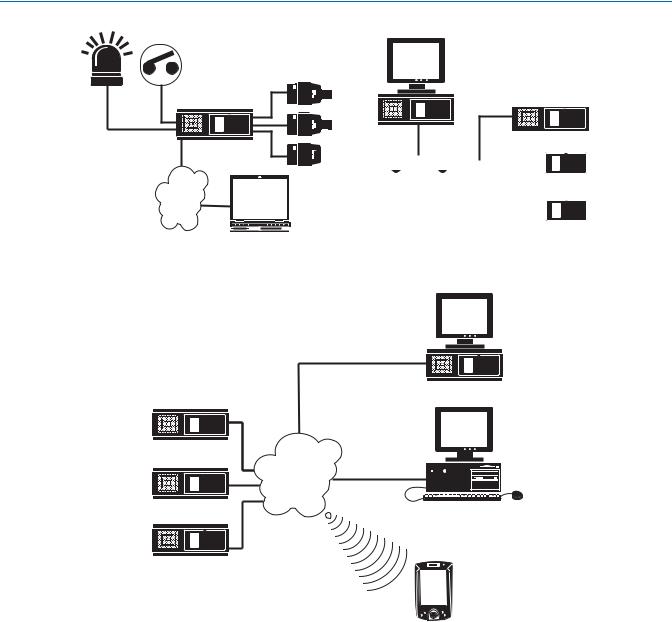
Application Examples
CAMERA
DX8000 SERVER DVR
LAN/WAN
PC CLIENT
Figure 1. System with Single DX8000
DX8000 SERVER DVR
LAN/WAN
DX8000 SERVER DVR
DX8000 SERVER DVR
DX8000  DX8000
|
|
|
|
|
|
|
|
|
|
|
|
|
|
|
|
|
|
|
|
|
|
|
|
|
FAST ETHERNET SWITCH |
|
|
||
|
|
DX8000 |
|||
|
|
|
|
|
|
|
|
|
|
|
|
|
|
|
|
|
|
|
|
|
|
|
|
DX8000
Figure 2. System with Multiple DX8000s
DX8000 SERVER DVR
WWW CLIENT
MOBILE CLIENT
Figure 3. System with Multiple DX8000s and Multiple Clients
Refer to the Operation/Programming manual for instructions on how to operate and program the DX8000 Series DVR.
14 |
C623M-C (3/05) |
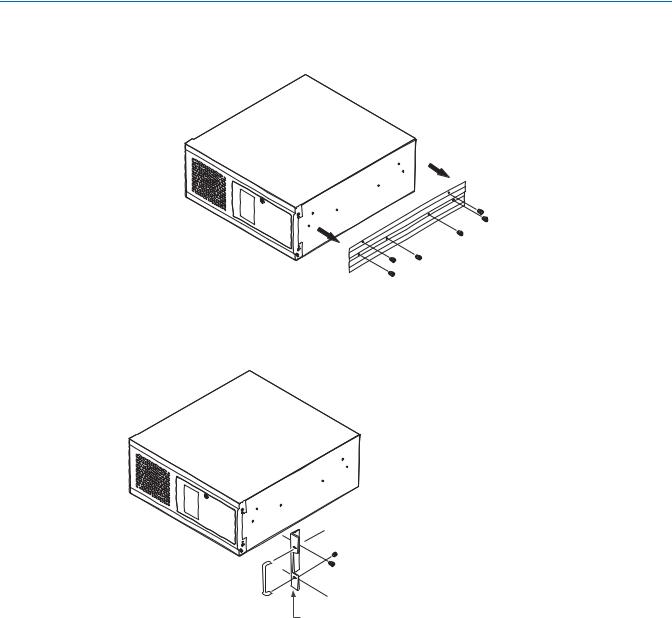
Equipment Rack Mounting
To install the unit in an equipment rack:
1. Remove the 12 screws fastening both left and right side plates to the unit. Save the side plates and screws for possible future use.
Figure 4. Remove Left and Right Side Plates
2.Attach the handles to the rack ears using the four provided 10-32 x 0.375-inch Phillips screws. Refer to Figure 5.
3.Using two of the supplied #4 sheet metal Phillips 0.375-inch pan head screws for each side, attach the rack ears to the unit.

 (4) SCREWS, 10-32 X 0.375-INCH
PHILLIPS, FLAT HEAD WITH WASHERS


 (4) SCREWS, #4, SHEET METAL, PAN HEAD,
PHILLIPS BLACK, 0.375-INCH (2 EACH SIDE)
RACK EAR
Figure 5. Attaching Rack Ears and Handles
C623M-C (3/05) |
15 |
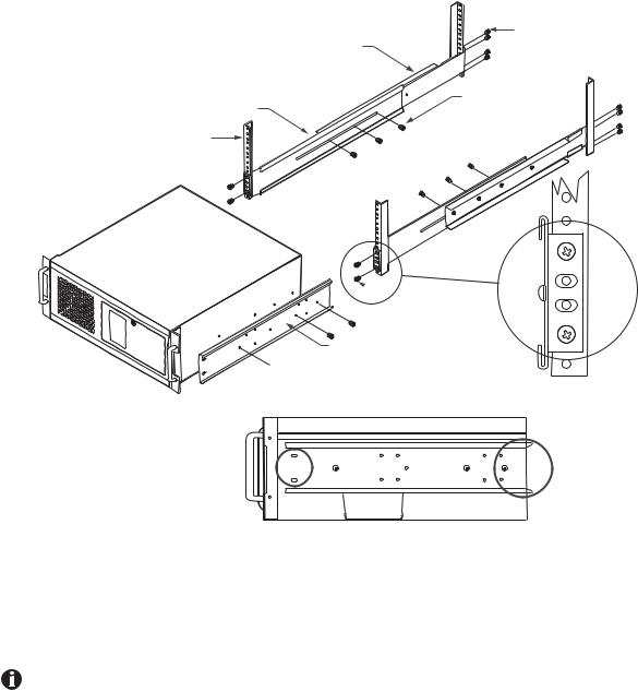
4.Using the remaining six #4 sheet metal Phillips 0.375-inch pan head screws, attach the two chassis brackets to the left and right sides of the unit. Refer to Figure 6.
5.Assemble both sets of front and rear mounting rails using three 8-32 x 0.375-inch pan head screws and locking washers for each side.
6.Using six of the 10-32 x 0.375 Phillips flat head screws per side, attach the assembled mounting rails to a 19-inch (48.26 cm) equipment rack or console.
7.Place the unit onto the mounting rails. It should slide in and out of the rack easily. This step may require two persons to lift and slide the unit into place.
8.Fasten the rack ears to the equipment rack using the four 10-32 x 0.750-inch pan head screws and nylon washers.
FRONT MOUNTING RAIL
RACK
RECORDER/VIEWSTATION 
|
(8) SCREWS, |
|
REAR MOUNTING RAIL |
10-32 X 0.375-INCH, |
|
FLAT HEAD |
||
|
(6) SCREWS,
8-32 X 0.375-INCH, PAN HEAD WITH LOCK WASHERS
 (4) SCREWS, 10-32 X 0.375-INCH FLAT HEAD
BRACKET (SIDE VIEW)


 (6) SCREWS, #4, SHEET METAL, PAN HEAD,
PHILLIPS BLACK, 0.375-INCH (3 EACH SIDE)
|
|
|
|
|
|
|
|
|
|
|
|
|
|
|
|
|
|
TAPERED ENDS |
|
|
|
|
SLOTTED HOLES |
|
|
||
|
|
|
|
|||
|
|
TOWARDS FRONT |
TOWARDS REAR |
|
||
|
|
OF UNIT |
OF UNIT |
|
||
Figure 6. Rack Mount Installation
 NOTE: Pelco recommends at least one rack unit (1.75 inches or 4.44 cm) of spacing between units.
IMPORTANT: Slots and openings in the cabinet provide ventilation and prevent the unit from overheating. Do not block these openings. Never place the DVR near or over a radiator or heat register. Do not place it in a built-in installation, such as a rack, unless proper ventilation is provided.
16 |
C623M-C (3/05) |
Back Panel Layout
|
|
|
|
|
|
|
|
|
|
|
|
|
|
||||
|
|
|
|
|
|
|
|
|
|
|
|
|
|
||||
|
IN1 |
|
|
IN2 |
|
|
IN3 |
|
|
IN4 |
|
|
|
IN5 |
|
IN6 |
|
OUT1 |
|
|
OUT2 |
|
|
OUT3 |
|
OUT4 |
|
OUT5 |
OUT6 |
||||||
ALARM INPUTS |
|
|
|
|
RELAY OUTPUTS |
|
|
|
|
||||||||
1 |
2 |
2 |
4 |
5 |
6 |
7 |
8 |
GND |
1 |
2 |
2 |
4 |
5 |
6 |
7 |
8 |
GND |
9 |
10 |
11 |
12 |
13 |
14 |
15 |
16 |
|
9 |
10 |
11 |
12 |
13 |
14 |
15 |
16 |
|
|
|
|
||
IN7 |
IN8 |
IN9 |
IN10 |
IN11 |
OUT7 |
OUT8 |
OUT9 |
OUT10 |
OUT11 |
|
|
|
CRT |
|
|
|
|
||
IN12 |
IN13 |
IN14 |
OUT12 |
OUT13 |
OUT14 |
|
Figure 7. Back Panel Layout
Autoranging AC Power Input (voltage range between 100 VAC and 240 VAC, 50/60 Hz)
Alarm Inputs – 16 normally closed inputs
Camera Outputs – 8 or 16 BNC camera outputs
Camera Inputs – 8 or 16 BNC camera inputs
Relay Outputs – 16 normally open outputs
S-Video Output (disabled)
Ultra SCSI Adapter (optional)
Programmable Analog Display Card Outputs (optional) – 2 BNC monitor outputs 4 RJ-45 Extended Peripheral Connectors (RS-422/RS-485 compliant)
Audio Inputs (optional) – 8 or 16 channels
VGA Monitor Output – 15-pin output
Audio Output
High-Speed USB 2.0 Ports – 2 USB ports on front of unit and 4 on rear of unit Ethernet Adapter Port – 100 Mbps port
Two 9-pin Serial Ports (disabled)
LPT1 Printer Port – 25-pin port
Keyboard (PS/2) Input
Mouse (PS/2) Input
IN15 |
IN16 |
OUT15 |
OUT16 |
C623M-C (3/05) |
17 |
Hardware Setup
BASIC CONNECTIONS
CAMERA
SPECTRA
POWER |
|
|
|
|
|
|
|
|
||
|
|
|
|
|
|
|
|
|||
|
|
|
|
|
VGA |
|
||||
CONNECTION |
|
|
|
|
|
|
||||
|
|
|
|
|
|
|
|
|||
|
|
|
|
|
|
|
|
|
|
|
|
|
|
|
|
|
|
|
|
|
|
MOUSE KEYBOARD
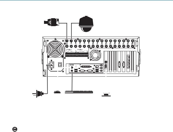
Figure 8. Basic Connections
Make the following connections on the rear of the recorder. Refer to Figure 8.
Connect the appropriate power cord to the back of the unit and to a power source.
NOTE: The DX8000 contains an autoranging power supply. It is recommended that the recorder be connected to an uninterruptible power supply (UPS) capable of supplying 2 A for 120 VAC power systems or 1 A for 230 VAC power systems.
Connect the mouse to the top PS/2 input.
Connect the keyboard to the bottom PS/2 input.
Connect a VGA monitor (not supplied).
Connect the cameras to the BNC connectors. Refer to Table A for video coaxial cable requirements. Connect power to the cameras.
Table A. Video Coaxial Cable Requirements
Cable Type* |
Maximum Distance |
|
|
RG59/U |
750 ft (229 m) |
RG6/U |
1,000 ft (305 m) |
RG11/U |
1,500 ft (457 m) |
|
|
*Minimum cable requirements: 75 ohms impedance All-copper center conductor
All-copper braided shield with 95% braid coverage When connecting cameras using these types of cable, use a patch panel. Do not connect these cables directly to the DX8000.
18 |
C623M-C (3/05) |
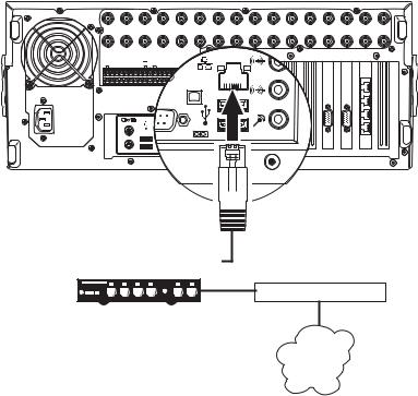
NETWORK SETUP
The DX8000 Series DVR supports remote viewing and administration in client-server and peer-to-peer configurations. The DX8000 is compatible with the TCP/IP protocol and Fast Ethernet (100BaseT) network connection. Consult your network administrator before installing the DX8000 to avoid possible network conflicts.
For TCP/IP access, connect the DX8000 to a 100 Mbps, switched Ethernet network. Use standard Cat5 or better UTP cable with RJ-45 connectors.
To configure the DX8000 hardware for network access:
1.Connect one end of the UTP cable to the network port on the back panel of the DX8000 as shown in Figure 9.
2.Connect the other end of the UTP cable to an available port on a standard Fast Ethernet switch.
|
IN1 |
|
|
IN2 |
|
IN3 |
|
|
IN4 |
|
|
|
IN5 |
|
IN6 |
IN7 |
IN8 |
IN9 |
IN10 |
IN11 |
IN12 |
IN13 |
IN14 |
IN15 |
IN16 |
|
OUT1 |
|
|
OUT2 |
|
OUT3 |
|
OUT4 |
|
OUT5 |
OUT6 |
OUT7 |
OUT8 |
OUT9 |
OUT10 |
OUT11 |
OUT12 |
OUT13 |
OUT14 |
OUT15 |
OUT16 |
||||||
ALARM INPUTS |
|
|
|
RELAY OUTPUTS |
|
|
|
|
|
|
|
|
|
|
|
|
|
|
||||||||
1 |
2 |
2 |
4 |
5 |
6 |
7 |
8 GND |
1 |
2 |
2 |
4 |
5 |
6 |
7 |
8 |
GND |
|
|
|
|
|
|
|
|
|
|
9 |
10 |
11 |
12 |
13 |
14 |
15 |
16 |
9 |
10 |
11 |
12 |
13 |
14 |
15 |
16 |
|
|
|
|
|
|
|
|
|
|
|
CRT
 CAT5 UTP
|
|
|
|
|
|
|
|
|
|
|
|
|
|
|
|
|
|
|
|
FAST ETHERNET SWITCH |
ROUTER |
||||||||
LAN/WAN
INTERNET
Figure 9. LAN/WAN Cable Connection
C623M-C (3/05) |
19 |

RS-422/RS-485 COMMUNICATION PORT SETUP
The DX8000 Series DVR features four independently configurable RJ-45 communication ports. All ports are compatible with both RS-422 and RS-485 interface standards. Each port can communicate with and control a variety of PTZ devices. Examples include Pelco’s Spectra™ III dome enclosures and Esprit® positioning systems. The example configuration illustrated in Figure 10 shows a DX8000 connected directly to up to four PTZ devices and indirectly to up to 16 devices through Pelco’s CM9760-CDU-T code distribution unit. Figure 11 illustrates the connection of a variety of RS-422/RS-485 compatible devices including the DX8000. This example highlights the P and D protocol data merging capability of Pelco’s CM9760-DMR data manager.
IMPORTANT: To operate properly, devices must be compatible with either the RS-422 or RS-485 interface standards and must be able to communicate using Pelco’s P, D, or Coaxitron® protocols.
1.Using unshielded twisted pair (UTP) cable, connect up to four RS-422/RS-485 compatible devices to the RJ-45 connector jacks provided on the rear panel of the unit.
 NOTE: Pelco recommends using 22 or 24 gauge UTP cable. Category 5 UTP is recommended for cable runs greater than 400 feet.
2.Set the communication parameters for both the DX8000 and the PTZ device. Communication parameters are baud rate, parity (odd or even), number of parity bits, number of data bits, and number of stop bits.
NOTE: Refer to RS-422/RS-485 Communication Port Software Configuration on page 42 for instructions on setting up your DVR’s communication parameters. Refer to the documentation included with your PTZ device for instructions on configuring its communication settings.
|
IN1 |
|
|
IN2 |
|
|
IN3 |
|
|
IN4 |
|
|
|
IN5 |
|
IN6 |
IN7 |
IN8 |
IN9 |
IN10 |
IN11 |
IN12 |
IN13 |
IN14 |
IN15 |
IN16 |
|
|
OUT1 |
|
|
OUT2 |
|
|
OUT3 |
|
OUT4 |
|
OUT5 |
OUT6 |
OUT7 |
OUT8 |
OUT9 |
OUT10 |
OUT11 |
OUT12 |
OUT13 |
OUT14 |
OUT15 |
OUT16 |
|
||||||
ALARM INPUTS |
|
|
|
|
RELAY OUTPUTS |
|
|
|
|
|
|
|
|
|
|
|
|
|
|
|
||||||||
1 |
2 |
2 |
4 |
5 |
6 |
7 |
8 |
GND |
1 |
2 |
2 |
4 |
5 |
6 |
7 |
8 |
GND |
|
|
|
|
|
|
|
|
|
|
|
9 |
10 |
11 |
12 |
13 |
14 |
15 |
16 |
|
9 |
10 |
11 |
12 |
13 |
14 |
15 |
16 |
|
|
|
|
|
|
|
|
|
|
|
|
|
|
|
|
|
|
|
|
|
|
|
|
|
|
|
|
|
|
|
|
|
|
|
|
|
|
|
|
PIN 8 |
|
|
|
|
|
|
|
|
|
|
|
|
|
|
|
|
|
|
|
|
|
CRT |
|
|
|
|
|
|
PIN 1 |
|
|
|
|
|
|
|
|
|
|
|
|
|
|
|
|
ROLLOVER CABLE |
|
|
|
|
|
|
|
PIN 1 = TX+ |
||||
|
|
|
|
|
|
|
|
|
|
|
|
|
|
|
|
|
|
|
|
|
|
|
|
|
|
|
|
PIN 2 = TX- |
|
|
|
|
|
|
|
|
|
|
|
|
|
|
|
|
|
|
|
|
|
|
|
|
|
|
|
|
. |
|
|
|
|
|
|
|
|
|
|
|
|
|
|
|
|
|
|
|
|
|
|
|
|
|
|
|
|
. |
|
|
|
|
|
|
|
|
|
|
|
|
|
|
|
|
|
|
|
|
|
|
|
|
|
PIN 8 |
|
|
. |
|
|
|
|
|
|
|
|
|
|
|
|
|
|
|
|
|
|
|
|
|
|
|
|
|
|
|
. |
|
CM9760-CDU-T |
|
|
|
|
|
|
|
|
|
|
|
|
|
|
|
|
|
|
|
|
|
|
|
|
|
|
|
|
|
|
|
|
|
|
|
|
|
|
|
|
|
|
|
|
|
|
|
|
|
|
|
|
|
|
|
PIN 7 = RX- |
|
|
|
|
|
|
|
|
|
|
|
|
|
|
|
|
|
|
|
|
|
|
|
|
|
|
|
|
SPECTRA |
|
|
|
|
|
|
|
|
|
|
|
|
|
|
|
|
|
|
|
|
|
|
|
|
|
|
PIN 1 |
|
PIN 8 = RX+ |
|
|
|
|
|
|
|
|
|
|
|
|
|
|
|
|
|
|
|
|
|
|
|
|
|
|
|
|
||
|
|
|
|
|
|
|
|
|
|
|
|
|
|
|
|
|
|
|
|
|
|
|
PIN 1 = TX+ |
|
|
|
||
|
|
|
|
|
|
|
|
|
|
|
|
|
|
|
|
|
|
|
|
|
|
|
PIN 2 = TX- |
|
|
|
||
|
|
|
|
|
|
|
|
|
|
|
|
|
|
|
|
|
|
|
|
|
|
|
. |
|
|
|
|
|
|
|
|
|
|
|
|
|
|
|
|
|
|
|
|
|
|
|
|
|
|
|
|
. |
|
|
|
|
|
|
|
|
|
|
|
|
|
|
|
|
|
|
|
|
|
|
|
|
|
|
|
|
. |
|
|
|
|
|
PTZ |
|
PTZ |
|
|
|
|
|
|
|
|
|
|
PTZ |
|
|
|
|
|
. |
|
|
|
|
|
||||
|
|
|
|
|
|
|
|
|
|
|
|
|
|
|
|
PIN 7 = RX- |
|
|
|
|||||||||
|
|
|
|
|
|
|
|
|
|
|
|
|
|
|
|
|
|
|
|
|
|
|
|
|
|
|||
|
|
|
|
|
|
|
|
|
|
|
|
|
|
|
|
|
|
|
|
|
|
|
PIN 8 = RX+ |
|
|
|
||
Figure 10. RS-422/RS-485 Configuration Example 1
20 |
C623M-C (3/05) |
|
CM9760-DMR |
CM6800 |
PTZ |
|
1-16 |
KBD300A
ROLLOVER CABLE
CM6800
|
IN1 |
|
|
IN2 |
|
IN3 |
|
|
IN4 |
|
|
|
IN5 |
|
IN6 |
IN7 |
IN8 |
IN9 |
IN10 |
IN11 |
IN12 |
IN13 |
IN14 |
IN15 |
IN16 |
|
OUT1 |
|
|
OUT2 |
|
OUT3 |
|
OUT4 |
|
OUT5 |
OUT6 |
OUT7 |
OUT8 |
OUT9 |
OUT10 |
OUT11 |
OUT12 |
OUT13 |
OUT14 |
OUT15 |
OUT16 |
||||||
ALARM INPUTS |
|
|
|
RELAY OUTPUTS |
|
|
|
|
|
|
|
|
|
|
|
|
|
|
||||||||
1 |
2 |
2 |
4 |
5 |
6 |
7 |
8 GND |
1 |
2 |
2 |
4 |
5 |
6 |
7 |
8 |
GND |
|
|
|
|
|
|
|
|
|
|
9 |
10 |
11 |
12 |
13 |
14 |
15 |
16 |
9 |
10 |
11 |
12 |
13 |
14 |
15 |
16 |
|
|
|
|
|
|
|
|
|
|
|
CRT
Figure 11. RS-422/RS-485 Configuration Example 2
NOTE: Different types of devices may require alternative cable wiring schemes. Wiring schemes commonly used by Pelco products include straight and rollover types. Refer to the documentation included with your PTZ device to ensure that cables and connectors are wired appropriately. Figure 12 illustrates straight and rollover cable wiring schemes
|
PIN |
PIN |
|
|
|
1 |
1 |
|
|
|
2 |
2 |
|
|
|
3 |
3 |
|
|
RJ-45 |
4 |
4 |
RJ-45 |
|
5 |
5 |
|||
|
|
|||
|
6 |
6 |
|
|
|
7 |
7 |
|
|
|
8 |
8 |
|
|
|
|
STRAIGHT CABLE |
|
|
|
PIN |
PIN |
|
|
|
1 |
1 |
|
|
|
2 |
2 |
|
|
|
3 |
3 |
|
|
RJ-45 |
4 |
4 |
RJ-45 |
|
5 |
5 |
|||
|
6 |
6 |
|
|
|
7 |
7 |
|
|
|
8 |
8 |
|
|
|
|
ROLLOVER CABLE |
|
Figure 12. Cable Wiring Schemes
C623M-C (3/05) |
21 |

ALARM INPUT INSTALLATION
The DX8000 has either 8 or 16 dry contact alarm inputs, depending on your system’s configuration. Each input is programmed to function as either a normally open or normally closed circuit.
To wire an alarm input:
1.Insert the green terminal blocks into the alarm sockets on the back panel of the recorder.
2.Connect one wire from the source device to one of the sensor input terminals 1 through 16.
3.Connect a second wire from the source device to a GND terminal.
4.Refer to the Operation/Programming manual for information on how to program the alarm inputs.
|
IN1 |
|
|
IN2 |
|
|
IN3 |
|
|
IN4 |
|
|
|
IN5 |
|
IN6 |
IN7 |
IN8 |
IN9 |
|
OUT1 |
|
|
OUT2 |
|
|
OUT3 |
|
OUT4 |
|
OUT5 |
OUT6 |
OUT7 |
OUT8 |
OUT9 |
||||||
ALARM INPUTS |
|
|
|
|
RELAY OUTPUTS |
|
|
|
|
|
|
|
||||||||
1 |
2 |
2 |
4 |
5 |
6 |
7 |
8 |
GND |
1 |
2 |
2 |
4 |
5 |
6 |
7 |
8 |
GND |
|
|
|
9 |
10 |
11 |
12 |
13 |
14 |
15 |
16 |
|
9 |
10 |
11 |
12 |
13 |
14 |
15 |
16 |
|
|
|
|
ALARM |
|
|
|
|
|
|
|
|
|
|
GND |
|
|
|
|
|
|
|
||
OUTPUT 1 |
|
|
|
|
|
|
|
|
|
|
|
|
|
|
|
|
|
|||
|
|
|
|
|
|
|
|
|
|
|
|
|
|
|
|
|
|
|
|
|
Figure 13. Alarm Terminal Installation
22 |
C623M-C (3/05) |
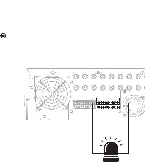
RELAY OUTPUT INSTALLATION
The DX8000 has either 8 or 16 relay outputs, depending on your system’s configuration. Each output is programmed to function as either a normally open or normally closed circuit. A signal from a relay output will operate the device connected to the output.
 IMPORTANT: The maximum relay power rating is 120 VAC, 0.5 A; 24 VDC, 1 A.
To wire a relay output:
1.Insert the blue terminal blocks into the relay sockets on the back panel of the recorder.
2.Connect one wire from the device to one of the relay output terminals 1 through 16.
NOTE: Relay outputs do not have to correspond numerically to alarm inputs. All sensor input and relay output actions can be linked through programming.
3.Connect a second wire from the relay device to a GND terminal.
4.Refer to the Operation/Programming manual for information on how to program relay outputs.
|
IN1 |
|
|
IN2 |
|
|
IN3 |
|
|
IN4 |
|
|
|
IN5 |
|
IN6 |
IN7 |
IN8 |
IN9 |
|
OUT1 |
|
|
OUT2 |
|
|
OUT3 |
|
OUT4 |
|
OUT5 |
OUT6 |
OUT7 |
OUT8 |
OUT9 |
||||||
ALARM INPUTS |
|
|
|
|
RELAY OUTPUTS |
|
|
|
|
|
|
|
||||||||
1 |
2 |
2 |
4 |
5 |
6 |
7 |
8 |
GND |
1 |
2 |
2 |
4 |
5 |
6 |
7 |
8 |
GND |
|
|
|
9 |
10 |
11 |
12 |
13 |
14 |
15 |
16 |
|
9 |
10 |
11 |
12 |
13 |
14 |
15 |
16 |
|
|
|
|
|
|
|
|
RELAY |
|
|
|
|
|
|
|
|
|
|
|
GND |
|
|
||
|
|
OUTPUT 1 |
|
|
|
|
|
|
|
|
|
|
|
|
|
|||||
|
|
|
|
|
|
|
|
|
|
|
|
|
|
|
|
|||||
Figure 14. Relay Terminal Installation
C623M-C (3/05) |
23 |
Software Setup
STARTING THE UNIT
Once the system has been installed and basic connections have been made, open the front panel of the DVR. Press the power switch. Wait while the unit starts (this may take several minutes).
POWER SWITCH
POWER HDD
USB
Figure 15. Front Panel and Power Switch
WARNING: Be sure to put on gloves before removing or inserting the filter.
24 |
C623M-C (3/05) |
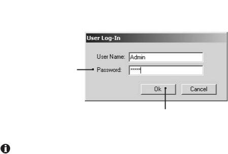
LOGGING IN FOR THE FIRST TIME
To access the features of the DX8000 Series DVR, each user must log in with a valid user name and password. There are four user access levels or groups that can be configured on the DX8000. Access levels range from the Administrator group, with the most rights and privileges, to the Restricted group, with the least rights and privileges. Refer to the Definition of User Access Levels section of the Operation/Programming manual for information on user group rights and permissions.
The DX8000 comes equipped with two built-in user accounts. Each time the unit is started, a default user account called “Guest” is automatically activated. The Guest account is granted only limited access to the DX8000 and is allowed no access to system configuration utilities. A second built-in user account, named “Admin”, provides full access to the operations and configuration features of the DX8000. To log in with the Admin account, follow the directions below.
To log in with the Admin account:
1.Click File > User Log-in.
2.Enter Admin in the User name field and Admin in the Password field.
 NOTE: User names and passwords are case-sensitive.
1. Click OK.
Figure 16. User Log-in Dialog Box
For security reasons, you are required to change the Admin password immediately after logging in for the first time. Passwords must be between six and ten characters long and cannot include spaces or special characters. Follow the directions on the next page to change the Admin password.
C623M-C (3/05) |
25 |
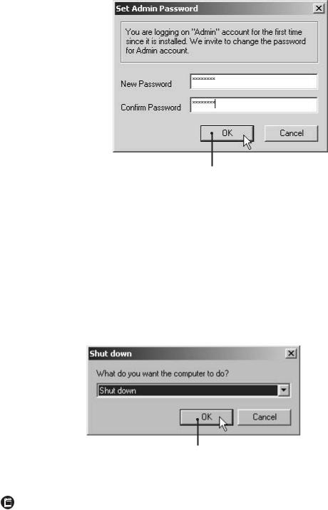
To complete the mandatory password change for the Admin account:
The Set Admin Password dialog box opens automatically.
1.Enter a new password in the New Password field.
2.Enter the password again in the Confirm Password field to confirm the password.
3.Click OK.


Figure 17. Set Admin Password Dialog Box
 NOTE: Only users with Administrator and Power User accounts are allowed access to DX8000’s setup functions.
SHUTTING DOWN
To shut down the DX8000 Series DVR:
1.Go to File > Exit.
2.Select Shut down.
3.Click OK.

Figure 18. Shut Down Dialog Box
NOTE: You must have Power User or Administrator access to shut down the DX8000. Refer to the Operation/Programming manual for information on user security levels. You must also have a Windows password to shut down. For information on the Windows default password, refer to the Important Security Information for System Admisnistrators guide.
26 |
C623M-C (3/05) |
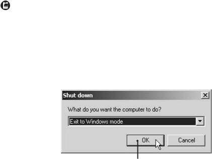
EXITING TO WINDOWS OPERATING SYSTEM
Some of the steps involved in the configuration of a DX8000 Series DVR require exiting to the operating system.
NOTE: You must have Power User or Administrator access to shut down the DX8000. Refer to the Operation/Programming manual for information on user security levels. You must also have a Windows password to exit from the DX8000 application to the Windows operating system. For information on the Windows default password, refer to the Important Security Information for System Admisnistrators guide.
To exit the DX8000 application and log into the Windows operating system:
1.Go to File > Exit.
2.Select Exit to Windows. The Shut down dialog box opens.
3.Click OK.

Figure 19. Shut Down Dialog Box
The Log On to Windows dialog box opens.
4. Enter the Windows password and click OK. The system logs you into the Windows operating system.
C623M-C (3/05) |
27 |
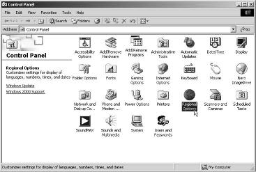
SETTING THE SYSTEM LANGUAGE
The DX8000 supports six languages. The DVR comes from the factory configured for English (United States). To configure the system properly for a language other than English, you must change the regional setting in the Windows operating system and the language setting of the DX8000. The following regional settings are available for the DX8000:
•English (United States)
•French (France)
•German (Germany)
•Italian (Italy)
•Portuguese (Brazil)
•Spanish (Spain)
English (United States) is the default setting.
CONFIGURING THE REGIONAL SETTING IN THE WINDOWS OPERATING SYSTEM
In the example below, the location is changed from English (United States) to Spanish (Spain).
1.Exit the DX8000 application and return to the Windows operating system. Refer to Exiting to Windows Operating System on page 27.
2.Click Start > Settings > Control Panel. The Control Panel appears. Double-click Regional Options.
Figure 20. Control Panel with Regional Options Selected
28 |
C623M-C (3/05) |
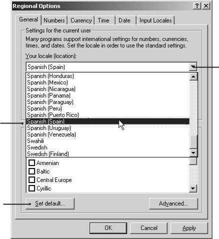
3.The Regional Options dialog box opens.
4.Click the arrow to open the location drop-down list.
5.Change the location to Spanish (Spain).
6.Click Apply.
7.Click Set Default.

Figure 21. Regional Options Dialog Box
C623M-C (3/05) |
29 |
Loading...