


Installation/Operation
CC3770 Series
Day/Night Camera
C2915M-E (08/05)
Pelco Worldwide Headquarters • 3500 Pelco Way, Clovis, CA 93612-5699 USA • www.pelco.com USA & Canada: Tel 800/289-9100 • FAX 800/289-9150
International: Tel: 1-559/292-1981 • FAX 1-559/348-1120
® Pelco, the Pelco logo, Spectra, Genex, Legacy, Esprit and Camclosure are registered trademarks of Pelco. ™Endura and ExSite are trademarks of Pelco
™DLP is a trademark of Texas Instruments, Inc. ™SuperHAD CCD is a trademark of the Sony Corporation.
© Copyright 2005, Pelco. All rights reserved.
[ 2 ] Pelco Manual C2915M-E (08/05)
CONTENTS |
|
|
IMPORTANT SAFETY INSTRUCTIONS .......................................................................................................... |
4 |
|
REGULATORY NOTICES ................................................................................................................................. |
5 |
|
DESCRIPTION ................................................................................................................................................... |
6 |
|
|
Models ........................................................................................................................................................ |
6 |
CAMERA LAYOUT ............................................................................................................................................. |
7 |
|
INSTALLATION .................................................................................................................................................. |
7 |
|
|
Lens Mounting ........................................................................................................................................... |
7 |
|
Camera Mounting ...................................................................................................................................... |
8 |
CONNECTIONS ................................................................................................................................................. |
8 |
|
|
Video Connections ..................................................................................................................................... |
8 |
|
Power Connections .................................................................................................................................... |
9 |
|
Color/Black-White Switching Connection ................................................................................................. |
11 |
|
RJ45-10 Connections .............................................................................................................................. |
12 |
|
Service Connection .................................................................................................................................. |
13 |
CAMERA SETUP ............................................................................................................................................. |
14 |
|
|
Lens Setup and Focus Procedures ......................................................................................................... |
14 |
|
Back Focus Adjustment ........................................................................................................................... |
15 |
|
Switch Settings ........................................................................................................................................ |
16 |
|
Camera Synchronization ......................................................................................................................... |
18 |
SPECIFICATIONS ........................................................................................................................................... |
19 |
|
WARRANTY AND RETURN INFORMATION ................................................................................................. |
22 |
|
LIST OF ILLUSTRATIONS |
|
|
1 |
Camera Layout ............................................................................................................................. |
7 |
2 |
AID/AIV Lens Connector .............................................................................................................. |
7 |
3 |
Camera Mounting ......................................................................................................................... |
8 |
4 |
Color/Black-White Remote Switching Connection ...................................................................... |
11 |
5 |
RJ45-10 Connector ..................................................................................................................... |
12 |
6 |
Service Connector ...................................................................................................................... |
13 |
7 |
AGC and ESC Switch Settings ................................................................................................... |
14 |
8 |
Back Focus Adjustment .............................................................................................................. |
15 |
9 |
Switch Settings ........................................................................................................................... |
16 |
10 |
Dusk and Dark Switching Thresholds ........................................................................................ |
17 |
LIST OF TABLES |
|
|
A |
Video Coaxial Cable Requirements ............................................................................................. |
8 |
B |
Wiring Distances for 5 VA Cameras (24 VAC/12 VDC) .............................................................. |
10 |
C |
Color/Black-White Manual Switching Modes .............................................................................. |
11 |
D |
RJ45-10 Pinouts ......................................................................................................................... |
12 |
Pelco Manual C2915M-E (08/05) |
[ 3 ] |

IMPORTANT SAFETY INSTRUCTIONS
1.Read these instructions.
2.Keep these instructions.
3.Heed all warnings.
4.Follow all instructions.
5.Do not use this apparatus near water.
6.Clean only with dry cloth.
7.Do not block any ventilation openings. Install in accordance with the manufacturer’s instructions.
8.Do not install near any heat sources such as radiators, heat registers, stoves, or other apparatus (including amplifiers) that produce heat.
9.Protect the power cord from being walked on or pinched particularly at plugs, convenience receptacles, and the point where they exit from tha apparatus.
10.Only use attachments/accessories specified by the manufacturer.
11. Use only with the cart, stand, tripod, bracket, or table specified by the manufacturer, or sold with the apparatus. When a cart is used, use caution when moving the cart/apparatus combination to avoid injury from tip-over.
12.Refer all servicing to qualified service personnel. Servicing is required when the apparatus has been damaged in any way, such as when the power supply cord or plug is damaged, liquid has been spilled or objects have fallen into the apparatus, the apparatus has been exposed to rain or moisture, the apparatus does not operate normally, or the apparatus has been dropped.
13.Apparatus shall not be exposed to dripping or splashing, and no objects filled with liquids, such as vases, shall be placed on the apparatus.
14.WARNING: To reduce the risk of fire or electric shock, do not expose this apparatus to rain or moisture.
15.Installation should be done only by qualified service personnel and conform to all local codes.
16.Unless the unit is specifically marked as a NEMA Type 3, 3R, 3S, 4, 4X, 6, or 6P enclosure, it is designed for indoor use only and it must not be installed where exposed to rain and moisture.
17.Use only installation methods and materials capable of supporting four times the maximum specified load.
18.CAUTION: These servicing instructions are for use by qualified personnel only. To reduce the risk of shock, do not perform any servicing other than that contained in the operating instructions unless you are qualified to do so.
19.Only use replacement parts recommended by Pelco.
20.Only power 12 VDC/24 VAC cameras from a UL Listed Class 2 power supply.
21.For outdoor use, an appropriate protective housing conforming to IP65 or better must be used. For UL, a UL Listed enclosure suitable for the application must be used.
22.DD/AI Lens Connector
The maximum load for a direct drive lens must not exceed 25 mA
The maximum load for an auto iris lens must not exceed 50 mA.
This symbol indicates that dangerous voltage constituting a risk of electric shock is present within this unit.
This symbol indicates that there are important operating and maintenance instructions in the literature accompanying this unit.
Please thoroughly familiarize yourself with the information in this manual prior to installation and operation.
[ 4 ] Pelco Manual C2915M-E (08/05)
REGULATORY NOTICES
This device complies with Part 15 of the FCC Rules. Operation is subject to the following two conditions: (1) this device may not cause harmful interference, and (2) this device must accept any interference received, including interference that may cause undesired operation.
RADIO AND TELEVISION INTERFERENCE CC3770H-6 and CC3770H-6X models:
This equipment has been tested and found to comply with the limits of a Class B digital device, pursuant to Part
15 of the FCC Rules. These limits are designed to provide reasonable protection against harmful interference in a residential installation. This equipment generates, uses, and can radiate radio frequency energy and, if not installed and used in accordance with the instructions, may cause harmful interference to radio communications.
However there is no guarantee that the interference will not occur in a particular installation. If this equipment does cause harmful interference to radio or television reception, which can be determined by turning the equipment off and on, the user is encouraged to try to correct the interference by one or more of the following measures:
•Reorient or relocate the receiving antenna.
•Increase the separation between the equipment and the receiver.
•Connect the equipment into an outlet on a circuit different from that to which the receiver is connected.
•Consult the dealer or an experienced radio/TV technician for help.
You may also find helpful the following booklet, prepared by the FCC: “How to Identify and Resolve Radio-TV
Interference Problems.” This booklet is available from the U.S. Government Printing Office, Washington D.C. 20402.
This Class B digital apparatus complies with Canadian ICES-003.
Cet appareil numérique de la classe B est conforme à la norme NMB-003 du Canada.
CC3770H-7 model:
This equipment has been tested and found to comply with the limits for a Class A digital device, pursuant to part
15 of the FCC Rules. These limits are designed to provide reasonable protection against harmful interference when the equipment is operated in a commercial environment. This equipment generates, uses, and can radiate radio frequency energy and, if not installed and used in accordance with the instruction manual, may cause harmful interference to radio communications. Operation of this equipment in a residential area is likely to cause harmful interference in which case the user will be required to correct the interference at his own expense.
Modifications not expressly approved by the manufacturer could void the user’s authority to operated the equipment under FCC rules.
This Class A digital apparatus complies with Canadian ICES-003.
Cet appareil numérique de la classe A est conforme à la norme NMB-003 du Canada.
Pelco Manual C2915M-E (08/05) |
[ 5 ] |
DESCRIPTION
CC3770 Series cameras are day/night, color/black-white switching video cameras with a 1/3-inch CCD imager. All cameras have a direct drive/auto iris lens connector and adjustable back focus, and they accept C and CS lenses.
Models
CC3770H-6 High resolution (480 color/530 b-w TV lines), SuperHAD™ CCD, 0.7 lux at F1.2 in color mode, 0.09 lux at F1.2 in black-white mode, NTSC, 12 VDC/24 VAC
CC3770H-6X High resolution (480 color/530 b-w TV lines), SuperHAD™ CCD, 0.7 lux at F1.2 in color mode, 0.09 lux at F1.2 in black-white mode, PAL, 12 VDC/24 VAC
CC3770H-7 High resolution (480 color/530 b-w TV lines), SuperHAD™ CCD, 0.7 lux at F1.2 in color mode, 0.09 lux at F1.2 in black-white mode, NTSC, 110-240 VAC
CC3770H-7X High resolution (480 color/530 b-w TV lines), SuperHAD™ CCD, 0.7 lux at F1.2 in color mode, 0.09 lux at F1.2 in black-white mode, PAL, 110-240 VAC
[ 6 ] Pelco Manual C2915M-E (08/05)

CAMERA LAYOUT
Figure 1. Camera Layout
INSTALLATION
Lens Mounting
The CC3770 Series camera can use fixed iris, manual iris, auto iris, or direct drive lenses. Automatic day/night operation is optimized for use with auto-iris lenses. Cameras are factory-set for CS-mount lenses, but are easily adjusted for C-mount lenses.
1. C-Mount Lens Only - Loosen the two back focus locking screws. Rotate the back focus adjustment ring fully counterclockwise before installing the C-mount lens (refer to the section on Back Focus
Adjustment).
2. Screw the lens onto the lens mount. Be careful to prevent dust from entering the space between the lens and the CCD element. If necessary, use clean, compressed air to remove any foreign matter.
3. Auto Iris Lens Only - Connect the auto iris lens to the four-pin iris drive connector located on the side of the camera. Pin connections for the iris drive connector are as follows.
Camera Connector |
PIN |
DC (AID) AUTO IRIS LENS |
VIDEO (AIV) AUTO IRIS LENS |
|
|||
|
1 |
Control coil positive (+) |
Not used |
|
2 |
Control coil negative (-) |
Lens positive supply |
|
3 |
Drive coil negative (-) |
Ground |
|
4 |
Drive coil positive (+) |
Video drive signal |
|
|
|
|
Figure 2. AID/AIV Lens Connector
Maximum load:
50 mA video auto iris lens
25 mA direct drive lens
Pelco Manual C2915M-E (08/05) |
[ 7 ] |
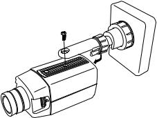
Camera Mounting
Mounting points are provided on the top and bottom of the camera and are used to mount the camera on a bracket or tripod. They are designed to accept standard photographic mounting bolts (1/4-inch UNC-20). The mounting bracket must be capable of supporting the weight of the camera and its lens.
NOTE: Some installation codes dictate that the mounting bracket must be capable of supporting up to four times the combined weight of the camera and lens.
Figure 3. Camera Mounting
CONNECTIONS
CC3770 Series cameras offer standard power and coax video connectors as well as an RJ45-10 connector that combines low voltage power and video (coax or UTP). These cameras also have a service connector allowing a video monitor to be connected locally to the camera using a composite video BNC cable.
Video Connections
To obtain a video output, connect a video coaxial cable terminated with a 75Ω BNC connector to the BNC socket marked VIDEO OUT on the rear of the camera. Refer to Table A for the type of video coaxial cable to use.
Table A. Video Coaxial Cable Requirements
Cable Type* |
Maximum Distance |
|
|
RG59/U |
750 ft (229 m) |
RG6/U |
1,000 ft (305 m) |
RG11/U |
1,500 ft (457 m) |
|
|
*Minimum cable requirements:
75 ohms impedance All-copper center conductor
All-copper braided shield with 95% braid coverage
Another way to transmit video is over unshielded twisted pair wiring through the RJ45-10 connector. Refer to the RJ45-10 Connections section. When outputting composite video through the BNC or RJ45-10, do not send UTP output to a passive UTP receiver. However it is acceptable to use an active UTP receiver for UTP output in combination with the other video connections.
[ 8 ] Pelco Manual C2915M-E (08/05)
 Loading...