


 Loading...
®
CM9740-CC1
System 9740™
Controller
Installation/
Operation Manual
C1508M-A (02/01)
Pelco • 3500 Pelco Way • Clovis, CA 93612-5699 USA • www.pelco.com In North America and Canada: Tel (800) 289-9100 • FAX (800) 289-9150 International Customers:Tel +1(559) 292-1981 • FAX +1(559) 348-1120

CONTENTS
Section |
|
|
|
|
Page |
|
1.0 |
IMPORTANT SAFEGUARDS AND WARNINGS ...................................................... |
5 |
||||
|
1.2 |
REGULATORY NOTICES .............................................................................. |
5 |
|||
2.0 |
OVERVIEW |
.............................................................................................................. |
|
|
6 |
|
|
2.1 |
INTRODUCTORY REMARKS ........................................................................ |
6 |
|||
|
2.2 |
MANUAL LAYOUT ......................................................................................... |
6 |
|||
3.0 |
BEFORE YOU BEGIN |
.............................................................................................. |
7 |
|||
|
3.1 |
A BRIEF NOTE .............................................................................................. |
|
7 |
||
|
3.2 |
FOR THE BEGINNER OR NEW USER, A FEW WORDS OF ADVICE AND |
||||
|
|
SOME .......................................................................................EXERCISES |
7 |
|||
4.0 |
INTRODUCTION ................................................................................TO THE CC1 |
8 |
||||
|
4.1 |
DESCRIPTION .............................................................................................. |
|
8 |
||
|
4.2 |
MODEL .......................................................................................................... |
|
|
8 |
|
|
4.3 |
SERCOM ...........................................................................BOARD CARDS |
10 |
|||
|
4.4 |
MOUNTING .................................................................THE CONTROLLER |
10 |
|||
|
4.5 |
CONNECTING .......................................................TO THE CONTROLLER |
11 |
|||
5.0 |
PHYSICAL INSTALLATION .................................................AND INITIALIZATION |
12 |
||||
|
5.1 |
CC1 INSTALLATION–CATEGORY .............................................................I |
12 |
|||
|
|
5.1.1 .............................................................. |
Category I–New Installation |
12 |
||
|
|
5.1.2 ........................Category I–Upgrade Replacement (Hardware Only) |
13 |
|||
|
|
5.1.3 ..........Category I–Upgrade Replacement (Hardware And Software) |
14 |
|||
|
|
5.1.4 .........................Category I–Upgrade Replacement (Software Only) |
15 |
|||
6.0 |
CC1 INITIALIZATION .............................................................................................. |
|
16 |
|||
|
6.1 |
SINGLE ..................................................................-NODE INITIALIZATION |
16 |
|||
|
|
6.1.1 ............................................................................. |
Diagnostic Screen |
16 |
||
|
|
6.1.2 ........................................................................................... |
Keyboard |
16 |
||
|
|
6.1.3 ........................................................MGR Program System Window |
17 |
|||
|
|
6.1.4 .............................................................................. |
Configuration File |
17 |
||
|
|
6.1.5 ....................................................................Online Node Dialog Box |
18 |
|||
|
|
6.1.6 ............................................Single-Node Hot Switch Configurations |
19 |
|||
7.0 |
CC1 CONTROLLER ..........................................................................OPERATION |
20 |
||||
|
7.1 |
MONITORING .................................................................CC1 FUNCTIONS |
20 |
|||
|
|
7.1.2 ..................................................................... |
The Diagnostic Screen |
20 |
||
|
|
........................................................ |
7.1.2.1 |
Monitor Box Examples |
23 |
|
|
|
........................................................ |
7.1.2.2 |
Monitor Box Allocation |
24 |
|
|
|
............................................ |
7.1.2.3 |
Screen Operation–Keystrokes |
25 |
|
|
7.2 |
SYSTEM ..............................................................................................TIME |
|
26 |
||
|
|
7.2.1 ......................Setting and Adjusting System Time–For Single-Node |
26 |
|||
|
|
7.2.2 ...................General Remarks Regarding System Time Adjustment |
28 |
|||
|
7.3 |
CC1 SYSTEM ...........................................................................INTEGRITY |
29 |
|||
|
|
7.3.1 .......................................Dynamically Updating a Configuration File |
29 |
|||
8.0 |
TROUBLESHOOTING/COMMON .....................................................PROBLEMS |
32 |
||||
|
APPENDIX ...........................................I INSTALLING THE MGR PROGRAM |
33 |
||||
|
APPENDIX ..............II DOS ENVIRONMENT AND COMMAND REFERENCE |
34 |
||||
|
APPDENDIX ..................................................................III MGR WRITE UTILITY |
41 |
||||
|
APPENDIX ...................................................................IV |
MGR READ UTILITY |
42 |
|||
|
APPENDIX .............................V REMOVING AN EXISTING MGR PROGRAM |
43 |
||||
|
APPENDIX ..........................................VI |
EDITING THE AUTOEXEC.BAT FILE |
44 |
|||
|
APPENDIX ................................................................................VII |
EXERCISES |
45 |
|||
9.0 |
SPECIFICATIONS................................................................................................... |
|
52 |
|||
10.0 |
WARRANTY .........................................................AND RETURN INFORMATION |
54 |
||||
2 | C1508M-A (02/01)

LIST OF ILLUSTRATIONS |
|
|
Figure |
|
Page |
1 |
CM9740-CC1 Front View ................................................................................... |
8 |
2 |
Rear View, General Identification ....................................................................... |
9 |
3 |
CM9740-CC1 Rear Connector Pinouts ............................................................. |
11 |
4 |
Multiple Receiver Hook-up ................................................................................ |
11 |
5 |
Category I–Bare Bones ..................................................................................... |
12 |
6 |
Category I–Fleshed Out .................................................................................... |
12 |
7 |
Single-Node Initialization .................................................................................. |
16 |
8 |
Initialization–System Window ............................................................................ |
17 |
9 |
Initialization– Configuration File ........................................................................ |
17 |
10 |
Initialization–Online Nodes ............................................................................... |
18 |
11 |
MGR Windows–A Precaution ............................................................................ |
18 |
12 |
Single-Node Hot Switch Configurations ............................................................ |
19 |
13 |
Display Screen Geometry ................................................................................. |
21 |
14 |
Diagnostic Screen and Monitor Box Geometry ................................................. |
22 |
15 |
Monitor Box Camera Switching ......................................................................... |
23 |
16 |
Monitor Box Preset Call .................................................................................... |
23 |
17 |
Monitor Box Allocation ...................................................................................... |
24 |
18 |
Monitor Box–F1 Allocation ................................................................................ |
24 |
19 |
Monitor Box–Allocate 3 to 1 .............................................................................. |
24 |
20 |
Monitor Box Switch ........................................................................................... |
24 |
21 |
Keys Command–Examples ............................................................................... |
26 |
22 |
Time Synchronization ....................................................................................... |
27 |
23 |
Configuration File Dialog Box ............................................................................ |
29 |
24 |
Hard Drive Update ............................................................................................ |
30 |
25 |
Dynamic Update Block Diagram ....................................................................... |
31 |
26 |
Sample AUTOEXEC.BAT File ........................................................................... |
35 |
27 |
CC1 Connections–Exercise I ............................................................................ |
45 |
28 |
CC1 Setup–Final ............................................................................................... |
45 |
29 |
CC1 Directory Structure .................................................................................... |
47 |
30 |
Root Directory ................................................................................................... |
47 |
31 |
9740 Directory ................................................................................................... |
47 |
32 |
The DOS Directory ............................................................................................ |
48 |
33 |
TESTPORT Directory ....................................................................................... |
50 |
34 |
MGR Program Location .................................................................................... |
51 |
CM9740-CC1 | 3

LIST OF TABLES |
|
|
|
Table |
|
|
Page |
A |
Command Key Functions .................................................................................. |
25 |
|
B |
CC1 Hardware Errors ........................................................................................ |
32 |
|
C |
CC1 System Errors ........................................................................................... |
32 |
|
D |
DOS Command Reference Directory ................................................................ |
38 |
|
LIST OF APPENDIXES |
|
||
Number |
|
|
Page |
APPENDIX I |
INSTALLING THE MGR PROGRAM ...................................................... |
33 |
|
APPENDIX II |
DOS ENVIRONMENT AND COMMAND REFERENCE ......................... |
34 |
|
APPDENDIX III MGR WRITE UTILITY ............................................................................. |
41 |
||
APPENDIX IV |
MGR READ UTILITY .............................................................................. |
42 |
|
APPENDIX V |
REMOVING AN EXISTING MGR PROGRAM ........................................ |
43 |
|
APPENDIX VI |
EDITING THE AUTOEXEC.BAT FILE ..................................................... |
44 |
|
APPENDIX VII |
EXERCISES ........................................................................................... |
45 |
|
4 | C1508M-A (02/01)
1.0 IMPORTANT SAFEGUARDS AND WARNINGS
Prior to installation and use of this product, the following WARNINGS should be observed.
1.Installation and servicing should only be done by qualified service personnel and conform to all local codes.
2.Unless the unit is specifically marked as a NEMA Type 3, 3R, 3S, 4, 4X ,6 or 6P enclosure, it is designed for indoor use only and it must not be installed where exposed to rain and moisture.
3.Only use replacement parts recommended by Pelco.
4.After replacement/repair of this unit’s electrical components, conduct a resistance measurement between line and exposed parts to verify the exposed parts have not been connected to line circuitry.
The product and/or manual may bear the following marks:
This symbol indicates that dangerous voltage constituting a risk of electric shock is present within this unit.
This symbol indicates that there are important operating and maintenance instructions in the literature accompanying this unit.
C A U T I O N :
RISK OF ELECTRIC SHOCK.
DO NOT OPEN.
Please thoroughly familiarize yourself with the information in this manual prior to installation and operation.
1.1 REGULATORY NOTICES
This equipment has been tested and found to comply with the limits of a Class B digital device, pursuant to part 15 of the FCC rules.These limits are designed to provide reasonable protection against harmful interference in a residential installation. This equipment generates, uses, and can radiate radio frequency energy and, if not installed and used in accordance with the instructions, may cause harmful interference to radio communications. However there is no guarantee that the interference will not occur in a particular installation. If this equipment does cause harmful interference to radio or television reception, which can be determined by turning the equipment off and on, the user is encouraged to try and correct the interference by one or more of the following measures:
•Reorient or relocate the receiving antenna.
•Increase the separation between the equipment and the receiver.
•Connect the equipment into an outlet on a circuit different from that to which the receiver is connected.
•Consult the dealer or an experienced radio/TV technician for help.
CM9740-CC1 | 5
2.0OVERVIEW
2.1INTRODUCTORY REMARKS
The CM9740-CC1 is the controller for the System 9740™ Matrix switching system. Although the CM9740-CC1 has a smaller hardware footprint than the CM9760-CC1, it can, with its “9740 specific” executable software, interface the same peripheral mix that the CM9760CC1 does, but on a reduced scale. In fact, the CM9740-CC1 can be installed as a node in a multi-node 9760 system, if desired.
In this manual, we attempt to meet the diverse needs of the user for information by discussing the most common type of configuration in which the CM9740-CC1 can be found. This configuration type, referred to here as “Category I,” is discussed further in the next section.
2.2 MANUAL LAYOUT
The topics touched on in Section 3.0 are important for the user to be familiar with in order to gain the most benefit from the discussions that take place later in Sections 5.0 and 6.0.The physical aspects of the CM9740-CC1 are discussed in Section 4.0. Section 5.0 discusses installation configuration scenarios, and Section 6.0 is concerned with controller initialization.
The basic installation type, which we refer to as “Category I,” is discussed from the standpoint of the CC1 as being (1) part of a New System Installation and (2) as an individual CC1 Replacement Installation within an existing system installation. We don’t exclude upgrade scenarios in our discussions, by which we mean that an existing system software and/or hardware mix (of which the CC1 is a par t) is upgraded to a newer version.
The Category I case is emphasized throughout and in more explicit detail with respect to the subtopics mentioned above, because, in most cases, one can extrapolate CC1 behavior there to more involved configurations.
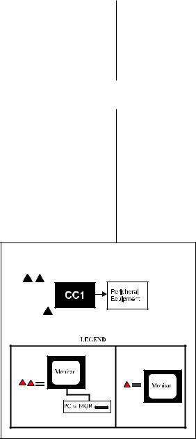
CATEGORY I |
Section 6.0 discusses initialization and what happens or should happen when the CC1 is powered on for the first time. We discuss various elements of system configuration, how they interact and the part the CC1 plays in it. What should happen, what can happen, and what to look for during initialization are also explored. Next, diagnostic screen functions, diagnostic key commands and those aspects of the MGR program that affect CC1 integrity are explored.
Finally, we briefly list some of the more common problems encountered dur ing initialization and suggest possible corrective action.
At any point in the manual where information appearing in an appendix has a bearing on the discussion at hand, that appendix is referenced. Based on one’s current knowledge and experience, one may or may not feel the need to consult it.
6 | C1508M-A (02/01)

3.0 BEFORE YOU BEGIN
3.1 A BRIEF NOTE
The CM9740-CC1 is a nonexpandable CPU, optimized for systems ranging from a 16 x 4 configuration (16 inputs and 4 outputs) to a 256 x 32 configuration (256 inputs and 32 outputs).
Beginner or New to 9740
If you are totally new to Pelco, or are familiar with Pelco but new to the 9740 matrix system, read on.
3.2FOR THE BEGINNER OR NEW USER,
A FEW WORDS OF ADVICE AND SOME EXERCISES
*MGR: The MGR program is an administrative extension of the 9740 executable. The executable resides on the hard drive of the CC1; the MGR program, when in use, resides on an external PC connected to the CC1.
**FLAT FILES: Flat files are information files based upon your particular system configuration that the system executable uses to know what it’s connected to and
how to talk to it.These flat files are created at the factory for your particular system configuration.For multi-node systems, a set of configuration files is created for each node (each node has its own CC1). The CM9740-CC1 cannot be used to construct multi-node systems. It can, however, appear as a node within a multi-node system. These flat files can be found in two different locations: (1) on the CC1 hard drive in the C:\9740 directory and (2) on the floppy disk labelled “Utilities.”
From a hardware standpoint, the CM9740-CC1 is ubiquitous to 9740 System operation. Section 4.0 addresses that aspect of the CC1.
In addition to its physical prominence, the CC1 is central to the software tasks required within the 9740 System. These tasks include configuration, initialization, and system control in operational mode.
Normally, CM9740-CC1 installations are problem free and follow an installation scenario that proceeds as follows:
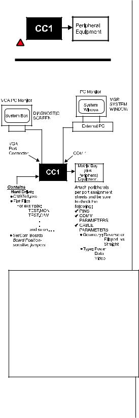
1.Everything is assembled together for the system configuration according to the provided roadmap, which exists in the form of port assignment sheets that tell you how everything physically relates to everything else–what device is attached to what port, and so on.
2.After all equipment and cables are installed and everything is finally hooked up, the power is turned on.
3.The system initializes.
Setup is complete and operation can begin. At some later point in time, however, if the existing system configuration needs to be changed, upgraded, or downgraded, then no matter how simple or complex your system is, there are two areas related to system software with which one should become thoroughly familiar:
•The directory structure of the CC1.
•The administrative extension of the system executable (the MGR* program) and the configuration files (flat files)** that comprise your specific system.
If you are not familiar with these two points, we encourage you to take the time
NOW, rather than be forced by necessity later, to become familiar with these two items.
It’s easy. Very little equipment must be connected. Your entire system does not have to be connected, nor does it have to be up and running to perform the two exercises that discuss these topics. If the previous statement applies in your case, or if you are responsible for implementing system configuration changes, then consult Appendix VII, which guides you through the entire process.
CM9740-CC1 | 7
4.0 INTRODUCTION TO THE CC1
4.1 DESCRIPTION
The CM9740-CC1 Controller is the main component and central operating hub of the System 9740. All components of the system connect to and communicate with the Controller via the ports located on the rear of the unit.
The CM9740-CC1 Controller mounts in a standard 19-inch (48.26 cm) rack space.
Default Hardware Configuration
a.3.5-inch Floppy Drive
b.Solid-state, non-volatile, flash memory
c.CPU
d.Mounting hardware
e.Keyboard
f.Mouse
g.2 SerCom cards
NOTE: The internal cards are manufactured or supplied by Pelco and contain no user-serviceable parts. Other than jumper settings or card replacement, any attempt to repair or modify the internal components of the CM9740-CC1 will void any applicable warranties.
4.2 MODEL
CM9740-CC1 |
CPU controller and processor, operates on 120-240 VAC, 50/60 Hz. |
|
(CE, UL, cUL) |
Front View
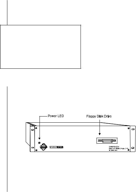
The front area of the controller consists of the items identified in the illustration in Figure 1:
Figure 1
CM9740-CC1 Front View
The CM9740-CC1 Controller is equipped with an internal power supply that provides all the operating voltages for the unit. * Cooling for the processor is provided by a CPU-mounted fan.
* The power socket outlet shall be installed near the equipment and shall be easily accessable.
8 | C1508M-A (02/01)

Rear View
The rear of the controller appears as illustrated in Figure 2.
This is the business end of the CM9740-CC1.
Figure 2
Rear View, General Identification
(RS-232 Wiring Connection between the CC1 and an External PC)


 TX
TX


 RX
RX


 RX
RX


 TX
TX
Refer to Figure 3 for COM port pinout identification
CM9740-CC1 | 9
4.3 SERCOM BOARD CARDS
Sercom Card installation at the factory configures the Sercom cards for the slot position locations they occupy in the unit.
Once you have an operational system, you can cycle through your IRQ/Slot position settings by toggling the ALT + A key combination on the keyboard associated with the diagnostic screen.
4.4 MOUNTING THE CONTROLLER
WARNING: Unplug the CC1 before attempting to install or remove any of the indi-
vidual components. Failure to do so could result in serious damage to the equipment.
The CM9740-CC1 Controller mounts in a standard 19-inch rack using standard mounting hardware (supplied with the unit). The unit occupies 3 RU (5.25 inches [13.34 cm]) of vertical rack space.
Before installing the unit, decide on the equipment orientation desired within the EIA rack and install the moveable ears on the unit accordingly. Secure as required.
10 | C1508M-A (02/01)
4.5 CONNECTING TO THE CONTROLLER
All system devices connect to the rear of the CM9740-CC1 controller. In general, any connectable device that can be used with the CM9760-CC1 can also be used with the CM9740-CC1.
D-type, 9-pin connectors are used for COM 1 and COM 2, while the VGA card connector is a 15-pin D-type connector. The PS/2 keyboard connection utilizes a standard 5-pin mini-Din connector.
The printer connector (used mainly for system logging and printouts) is a 25-pin D-type connector. A completely operational System 9740 will more than likely require the addition of more equipment to the controller; namely, such items as a VGA monitor, or a PS/2 keyboard and printer.To connect this equipment, simply plug the desired piece of equipment into the appropriately labeled port. For connector information, refer to Figures 3 and 4.
Figure 3
CM9740-CC1 Rear Connector Pinouts
Figure 4
Multiple Receiver Hook-up
NOTE: When a Sercom port is used to interface multiple receivers, the distance “D” between the pick-off points and any receiver should be 3 feet (.91 m) or less
“D” (see note)
CM9740-CC1 | 11
5.0 PHYSICAL INSTALLATION AND INITIALIZATION |
||
5.1 CC1 INSTALLATION–CATEGORY I |
||
Figure 5 |
|
|
Category I–Bare Bones |
Preliminary |
|
|
||
|
For new installations, you normally receive a configuration setup or dia- |
|
|
gram and a port assignment sheet for your specific installation. Pay close |
|
|
attention to these when setting up your system. |
|
|
Items specific to CC1 production for units leaving the factory include the following: |
|
|
1. |
Configuration files (flat files) that correspond to your specific system |
|
|
configuration are created and exist, as a set, in two locations. One set |
|
|
is located within the C:\9740 directory on the drive of the CM9740-CC1. |
Figure 6 |
|
The other backup set is located on a floppy disk labeled Utility Disk. |
|
|
|
Category I–Fleshed Out |
2. |
The directory structure of your drive has been set up and includes |
|
||
|
|
those items alluded to in Section 3.2 and discussed in detail in Ap- |
|
|
pendix VII of this manual. |
|
3. |
The MGR program, which is a software extension of the 9740.EXE, |
|
|
exists on a five-unit floppy disk installation set that accompanied your |
|
|
unit. This program should be installed on the external PC that will be |
|
|
connected to COM 1 on the rear of the CC1. The MGR program |
|
|
should be loaded on the external PC and the PC should be connected |
|
|
to the CC1 before any power to the CC1 is turned on in preparation |
|
|
for the initialization process. The inclusion of MGR operability is not a |
|
|
necessary component of the initialization process; however, its exclu- |
|
|
sion would mean the loss of a valuable tool for viewing, verifying, and |
|
|
probing various aspects of that process. |
|
5.1.1 Category I–New Installation |
|
|
1. |
CC1s are normally installed in close physical proximity to matrix bays, |
|
|
as these are the first items to be connected to the rear of the CC1, start- |
|
|
ing at Port 5 on the rear of the CC1. |
|
|
Keyboards are installed after matrix bays; then, after that, everything |
|
|
else is installed on a “next available port” basis according to the port |
|
|
assignment sheets. |
|
2. |
If the MGR program is to be used, it is installed on an external PC |
|
|
connected to COM1 on the rear of the CC1. The cable between the |
|
|
external PC and CC1 is not supplied by Pelco. Use the convenient |
|
|
pinout information given in Figures 2 and 4 for wiring up the cable. If you |
|
|
followed the exercise for the beginner referenced in the first part of the |
NOTE: Remember that each peripheral device |
|
manual, you have already installed the MGR on an external PC. If that |
is unique and has its own requirements. If ques- |
|
is not the case or if you wish to use a different PC, then the MGR pro- |
|
gram must be installed on the PC at any point before power is applied |
|
tions arise with respect to any of the parameters |
|
|
|
to the system. Use the quick-star t installation guide in Appendix I to |
|
for an individual piece of equipment, it is impera- |
|
|
|
install the program on the external PC. |
|
tive that you consult the manuals for the device |
|
|
|
|
|
in question. |
3. |
Connect the external VGA PC monitor to the VGA por t provided on the |
|
||
**Note that video paths are independent of the |
|
rear of the CC1. This will display your diagnostic screen. |
|
|
|
9740.EXE being in operational mode. The fact |
4. |
Once you are satisfied with the physical hook-up of all peripheral de- |
that pictures appear on monitors when periph- |
|
vices and have double-checked all communication parameters and |
eral equipment is turned on does not mean |
|
switch settings, you are ready to do the following: |
that the system is operational. It is a neces- |
|
|
sary item for proper system operation, but has |
|
a. Turn on power to all peripheral equipment connected to the CC1.** |
nothing to do with system initialization. |
|
|
b. Apply power to the CC1.
5.Proceed to the Section 6.1, which discusses system initialization for single-nodes.
The next example is that rare case where the act of having saved a current copy of your configuration files (flat files) can save you a lot of work.
12 | C1508M-A (02/01)

NOTE: Normally, one thinks of hardware and software as separate entities and that upgrading or replacing one would not significantly affect the upgrade or replacement of the other. For new system configurations, this is not a problem. Areas of concern do arise, however, when upgrading or replacing existing units within systems that are out in the field. If the replacement equipment contains preloaded software (for example, the CC1) or contains programmed ROMs (for example, the CM9760-KBD), care must be taken.You must make a reasonable effort to ensure that the new hardware and the software it contains are compatible with the system within which it is to be placed.
NOTE: You should always save your old executables and flat files, along with your autoexec.bat file, in case the upgrade installation doesn’t pan out.
NOTE: You should always have a list of the current version levels of all the software that you are running on your system or at least know where to find the information. In general, it’s best to make a list as soon as possible after receiving new software or equipment containing software and keep the list current.
The list would include version information on the following:
1.The CM9740.exe
2.The 9760MGR software
3.The CM9760-KBDs
5.1.2 Category I–Upgrade Replacement (Hardware Only)
Object: Physical Replacement of the CC1
Assumptions:
•The CC1 to be replaced is part of an existing operational system configuration that has failed.
•The software environment that existed on the failed CC1 is to be used on the replacement CC1.
To physically replace the CC1:
1.Shut down any parts of the system that are running and turn off power (where applicable). We assume here that the failed CC1’s power is already off.
2.Disconnect all peripheral equipment from the failed CC1, noting what is connected to what.
3.Connect a PS/2 keyboard to the replacement CC1 and power it up independent of the system to which it will be connected.
4.Take your most current copy of configuration files (flat files) for the system in question and copy them to the C:\9740 directory on the hard drive of the replacement CC1. If you don’t have a set, you are going to have create one from scratch.
5.The 9740.EXE that exists on the replacement CC1 will be configured with the latest revision of system software.
6.When power is applied to the replacement CC1 in step 3, it should boot to the diagnostic screen after loading system files. This is a reflection of the standard factory configuration of the autoexec.bat file and nothing else.
NOTE: You can choose to edit and effect changes in the autoexec.bat file after the system is hooked up and power is turned on. If you do, just keep in mind that the following instructions assume that you have already made the changes referenced.
7.Once you have loaded a copy of your current configuration files, the old executable and the adjusted autoexec.bat (if applicable) on the new CC1, turn off power to the CC1.
8.Replace the old unit with the new CC1 and reinstall, connector for connector, all peripheral equipment disconnected in step 2.
9.Turn on power to all the peripheral equipment and to the new CC1. Check system initialization and look for system errors. Correct any found, and then, again, save to disk any copies of your configuration files and any other files that you don’t want to have to create or scrounge around for should similar circumstances occur in the future.
CM9740-CC1 | 13

**IMPORTANT NOTE
If you are doing an across-the- board upgrade of the system software associated with the CC1 (namely, the MGR program and the system executable), then any CM9760-KBD used with the upgraded system must also contain software that is compatible with the upgrade.
5.1.3 Category I–Upgrade Replacement
(Hardware and Software)
Object: Physcial replacement of the CC1, in conjunction with softw are upgrade or replacement.
Assumptions:
•The CC1 to be replaced is part of an existing, operational, system configuration.
•The operational software within the existing CC1 needs to be replaced and/or upgraded, depending on circumstances covered in the steps below.
1.Repeat steps 1, 2, and 8 of the previous section, ignoring remarks about CC1 status. Do not, however, reconnect the external PC (containing the MGR program) to the new CC1 just yet.
The status of the new CC1 and its associated software files are as follows:**
•The latest 9740 executable will reside in the C:\9740 directory on the drive of the CC1. Backups of the executable are on the Operations and Utility disks that accompanied the shipment of the replacement CC1.
•A five-disk set of the latest MGR program also accompanied the shipment.
2.If the software version of your current MGR program is less than that of the MGR program in the upgrade package, then the latest MGR software must be installed on your external PC.
To accomplish that, do the following:
a.Remove your old MGR software according to Appendix V.
b.Install the new MGR software using the five-disk set of the System Manager. Use the quick-start guide located in Appendix I of this manual for instructions.
3.Connect any new equipment that is part of your hardware upgrade to the appropriate port(s) on the rear of the CC1, according to the installation instructions found in the manual(s) accompanying the new equipment.
4.If the equipment connected in step 3 requires updates to your existing configuration files (which it will if the hardware portion of the upgrade necessitated the use of any additional Sercom ports), then do the following; otherwise, proceed to step 6:
a.Power-up the external PC containing the MGR program and use the READ utility to read in your existing configuration set (flat files) into the MGR program (refer to Appendix IV, if needed).
b.Make the necessary changes in your current configuration files to accommodate any new equipment. As part of those changes, don’t forget to enter a PIN for the new equipment in the COMMS file and to assign operator access. Consult the applicable device manual and the MGR documentation as needed until all the parameters that need to be changed are taken into account.
c.Save your updated flat files to the database and then use the WRITE utility of the MGR program to write out the changed configuration set to floppy disk.
d.Copy the new configuration set into the C:\9740 directory of the new CC1 (refer to Appendix II, if necessary).
5.Reconnect the external PC containing the upgraded MGR software to the new CC1 and load the upgraded configuration set into the C:\9740 directory of the new CC1. Proceed to step 7.
6.Reconnect the external PC containing the upgraded MGR software to the new CC1 and load your existing flat files into the C:\9740 directory of the new CC1.
7.Repeat step 9 of Section 5.1.2.
14 | C1508M-A (02/01)

5.1.4 Category I–Upgrade Replacement (Software Only)
Object: To upgrade current system software to the latest available.
Assumptions:
•You’re currently running a fully operational CC1 to which is attached an external PC containing the MGR program.
•You have ordered the current software upgrade package for the CC1.
•You have also ordered (if applicable) compatible keyboard software for use with the system software upgrade (CM9760-KBD-XXX).
To upgrade your system software:
1.Halt system operation (if applicable) with the familiar Ctrl + Q key combination.
2.Replace the old MGR program on the external PC with the upgrade MGR program by doing the following:
a.Remove the old MGR program, following the instructions in Appendix V.
b.Install the new MGR program using the quick-start guide in Appendix I.
3.Use the READ utility of the just–installed MGR program to read in a copy of your current configuration files.
4.Effect any changes desired, save the files to the database and use the WRITE utility to write a copy of your configuration files to floppy disk. Make sure you continue to use the same global prefix name for your configuration set that you used before or you will have to change your autoexec.bat file later.
5.Copy the new configuration set to the C:\9740 directory on the hard drive of the CC1 and overwrite any files existing there.
6.Copy the latest system executable (CM9740.EXE) [located on the “Utility Disk”] and overwrite the old executable located in the C:\9740 directory of the CC1.
7.Upgrade the keyboard software (if applicable) using the appropriate KBD upgrade kit.
8.Attach all equipment not yet connected to the CC1.
9.Power-up all peripheral equipment; turn on the CC1.
10.Initialize the system and check for errors.
CM9740-CC1 | 15

6.0 CC1 INITIALIZATION
The initialization process occurs during the time that the CM9740.EXE program is booting up. During this time configuration files and diagnostic programs are loaded enabling system parameters for CCTV matrix operation. As the initialization process proceeds, the executable calls for its associated diagnostic and corresponding information screen. The primary visual verification of successful initialization is signaled by the information displayed there. That, and other indicators of successful initialization (for example, the 9760 KBD LCD screen and the Manager system window, which are both discussed in the next section) give a range of items to check to verify successful initialization.
In the absence of perfect system initialization, what you hope to see is verification that the system is a least up and running. Small problems might be indicated by system messages other than the one you wanted to see, but you are essentially “in business.”
6.1 SINGLE-NODE INITIALIZATION
As just discussed, normal initialization is the result of a successful boot process, which, more often than not, ends with a display of its associated diagnostic screen indicating success. It will do this either because (1) it was configured that way at the factory or (2) because the autoexec.bat file was edited by the user to call the appropriate executable during the boot process.
6.1.1 Diagnostic Screen
Initialization begins when the CC1 is turned on (we assume all peripheral equipment is powered on). The boot process executes as a standard DOS boot. When the executable in the autoexec.bat file is called, a bare outline of the diagnostic screen appears on the attached monitor. A syncopated series of messages appears in the System box until the process ends and, if successful, a “Setup Complete” diagnostic screen like that shown in Figure 7 appears.
Figure 7
Single-Node Initialization
6.1.2 Keyboard
Within your system configuration, you may also have other devices connected that give online system indications, some more helpful than others.
For example, consider the CM9760-KBD. If you have one attached to your system, the LCD screen display will look as follows before the system boots:
▼
When the system boots, and initialization is complete, the keyboard LCD display will change from the above LCD screen to the following one:
SYSTEM 9740 v7.8 |
The keyboard will go through this display process regardless of the type of configuration to which it is connected.
16 | C1508M-A (02/01)

Figure 8
Initialization–System Window
Figure 9
Initialization– Configuration File
6.1.3 MGR Program
System Window
That leaves the MGR system window, which is part of the MGR program proper. If you have an external PC connected to the CC1 that contains the MGR program, there are multiple indications of online status associated with this program that can be checked.
Just before the boot process, have the MGR program up and running with the system window showing. Click on the SysWindow icon as indicated in Figure 8; the window should be blank. If it isn’t, close the system window and answer “No” to the dialog inquiry about retaining current system window messages. Then, reopen the window and it will be blank. At the end of the initialization process when the “Setup Complete” message appears on the diagnostic screen, a corresponding display indicating system status will appear in the system window of the MGR program, like that shown in Figure 8, indicating that the system is up and online.
6.1.4 Configuration File
In addition to the SysWindow message regarding online status, you can click on the 9760 Setup icon on the MGR program toolbar, which will bring up the Configuration Files dialog box (refer to Figure 9). On the far right side of the line indicating the Node # and the “group” configuration file name associated with that node is another indication that the system is online. The word “Online” appears, as shown in Figure 9. A dash “–”, normally occupies that spot when the system is not online.
CM9740-CC1 | 17
Loading...