

Parkside PDWE 8 A1 Operation And Safety Notes Translation Of The Original Instructions
AIR FILTER REGULATOR AND LUBRICATOR
PDWE 8 A1
GB IE NI
AIR FILTER REGULATOR AND LUBRICATOR
Operation and Safety Notes
Translation of the original instructions
DE
DRUCKLUFT WARTUNGSEINHEIT
Bedienungs- und Sicherheitshinweise
Originalbetriebsanleitung
IAN 292166
DK
TRYKLUFT-SERVICEENHED
Brugs- og sikkerhedsanvisninger
Oversættelse af den originale driftsvejledning
GB
IE
DK
NI
DE

GB IE NI
Before reading, unfold the page containing the illustrations and familiarise yourself with all functions of
the device.
DK
Før du læser, vend siden med billeder frem og bliv bekendt med alle apparatets funktioner.
DE
Klappen Sie vor dem Lesen die Seite mit den Abbildungen aus und machen Sie sich anschließend mit allen
Funktionen des Gerätes vertraut.
GB/IE/NI Operation and Safety Notes Page 5
DK Brugs- og sikkerhedsanvisninger Side 15
DE Montage-, Bedienungs- und Sicherheitshinweise Seite 25
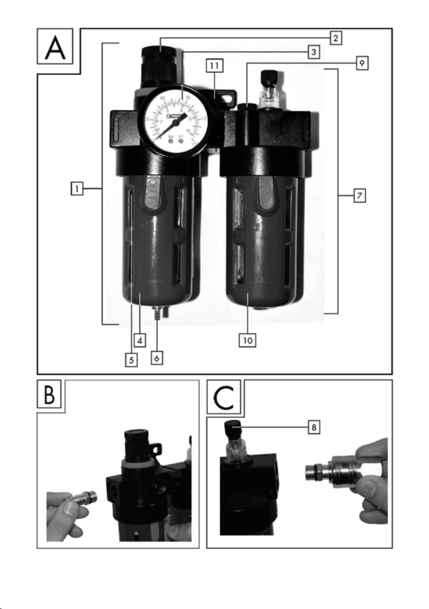


Table of contents
Table of pictograms used ...............................................................................Seite 6
Introduction ...........................................................................................................Seite 6
Intended use ...............................................................................................................Seite 6
Residual risk ................................................................................................................Seite 6
Parts description ..........................................................................................................Seite 6
Technical specifications ................................................................................................Seite 7
Package contents .........................................................................................................Seite 7
Safety notes ..........................................................................................................Seite 7
Safety notes for using pneumatic devices ..............................................Seite 8
Before starting up ..............................................................................................Seite 9
Installation ............................................................................................................Seite 10
Filling the oil mist unit ...................................................................................................Seite 10
Starting up .............................................................................................................Seite 10
Setting the working pressure ........................................................................................Seite 11
Filter unit ....................................................................................................................Seite 11
Condensate drain via the drain valve .............................................................................Seite 11
Oil mister unit..............................................................................................................Seite 11
Cleaning and maintenance ............................................................................Seite 12
Warranty and service information ............................................................Seite 12
Warranty conditions.....................................................................................................Seite 12
Extent of warranty ........................................................................................................Seite 12
Processing of warranty claims .......................................................................................Seite 13
Environmental notes and
disposal information .........................................................................................Seite 13
Disposal of the
maintenance unit .........................................................................................................Seite 13
GB/IE/NI 5
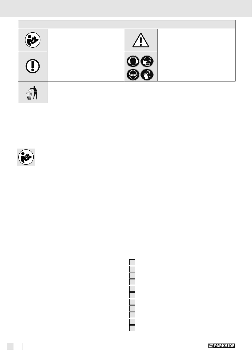
Table of pictograms used / Introduction
Table of pictograms used
Be Read the operating
instructions!
Note
Dispose of the pneumatic devices
and packaging environmentally
compatibly
Air-driven maintenance unit
PDSP 8 A1
Introduction
Congratulations! You have purchased
one of our high-quality devices. Before
setup or first use, please familiarise
yourself with the product. To do so, please read
through the following operating and safety
instructions carefully. This tool must be set up or
used only by people who have been trained to do
so.
KEEP OUT OF THE REACH OF CHILDREN!
Observe warnings and the safety
instructions!
Wear hearing protection,
respirator / dust mask, goggles,
and protective gloves.
or industrially.
Residual risk
Even if you operate the device according to the
instructions, there will always be residual risks
remaining. The following risks may occur in connection with the build and execution of this pneumatic
maintenance unit:
Danger from beating compressed air hoses.
Danger of falling from compressed air hoses
lying around.
Reduce the residual risk by carefully using the
device as intended and observing all instruction.
Intended use
The air-driven maintenance unit serves to oil the
compressed air for pneumatic tools and at the
same time filters condensation from the compressed
air. Use the products only as described and only
for the specific applications as stated. Keep these
instructions in a safe place. Ensure you hand over
all documentation when passing the product on to
anyone else. Any use that differs to the intended
use as stated above is prohibited and potentially
dangerous. Damage or injury caused by misuse
or disregarding the above warning is not covered
by the warranty or any liability on the part of
the manufacturer. The device was designed for
household use and must not be used commercially
GB/IE/NI6
Parts description
After unpacking the product, please check that
the device is in perfect condition. Do not use the
product if it is defective.
1
Filter unit
2
Compressed air controller
3
Compressed air pressure gauge
4
Condensate collection container
5
Filter insert
6
Drain valve
7
Oil mister unit
8
Screw to change the lubrication
9
Oil refilling inlet
10
Container for compressed air oil
11
Holder for wall mounting

Introduction / Safety notes
Technical specifications
Max. working pressure: 8 bar
Oil: Suitable compressor oil
Package contents
1 pneumatic air maintenance unit
Safety notes
Please read the operating instructions
with care and observe the notes
described. Familiarise yourself with
the device, its proper use and the
safety notes based on these operat
-
ing instructions.
The rating plate container all
technical data of this pneumatic
maintenance unit; please learn about
the technical features of this device.
This device can be used by children
16 years and older and also by per
sons with reduced physical, sensory
or mental capacities or a lack of
experience and knowledge if they
are supervised or they have been
instructed with regard to the safe use
of the device and they understand
the dangers it presents. Do not allow
children to play with the product.
Cleaning and user maintenance must
not be performed by children without
supervision.
In connection with a compressor, the
maintenance unit serves maintenance
and care (e.g. filtering, oiling and
regulation) of your pneumatic tools.
The maintenance unit must only be
used with a pneumatic compressor.
When using the device, observe the
maximum compressed air values of
the connected tools and check them
several times during use. This product
is only intended for private use. The
maintenance unit must only be used
as intended. Any further, deviating
use is forbidden!
Consideration of the safety note sin
the operating instruction and the
assembly instructions are also part
of intended use. The manufacturer or
dealer assumes no liability for any
damage caused by non-intended or
wrong use.
Only accessories suitable for this
product must be used. Persons who
use the pneumatic maintenance unit
and who may perform maintenance
work are obligated to familiarise
themselves with it. They also must be
informed about potential dangers.
The applicable accident prevention
provisions must be correctly and
conscientiously observed.
GB/IE/NI 7

… / Safety notes for using pneumatic devices
Any changes to the pneumatic
maintenance unit exclude liability of
the manufacturer and any connected
damage.
Safety notes for using
pneumatic devices
Important!
Always keep the compressed air
hose firmly in your hands when
releasing a connection. The lash
ing backlash of the compressed
air hose may cause injury.
The compressed air maintenance
unit must be installed before it can
be safely taken into operation. A
stable wall is suitable for installa
tion (with screw connections).
We recommend only using
the lubricants specified by the
manufacturer.
Never exceed the indicated
maximum pressure values of the
maintenance unit.
The pneumatic maintenance unit
must only be connected to a com
pressed air source that does not
exceed the working pressure of
8 bar.
Do not put the compressed air
lines near any heat, oils, heat and
sharp edges.
The maintenance unit must only
be operated in connection with a
pneumatic compressor.
Use of other compressed air
sources, such as a compressed air
cylinder, is forbidden. There is a
danger of fire and/or explosion.
Make sure that children and
persons with limited physical or
mental capacities are kept away
from the maintenance unit and the
connected compressed air tools.
Only use genuine spare parts for
repairs. Any non-genuine spare
parts may cause severe damage.
When conducting any mainte-
nance, setting and repair work,
always disconnect the mainte
nance unit from the compressed
air supply first.
Changes to the maintenance unit
are forbidden.
Use the maintenance unit only
when it is in an impeccable con
dition. In doubt, use a specialist's
advice.
Have repairs only conducted by
qualified specialists.
User safety
Try out the pneumatic tool
used before every use. Never
use the compressed air maintenance
unit with any higher operating
pressure then indicated in the tech
nical data. Before you connect your
pneumatic tools to the pneumatic
GB/IE/NI8
Safety notes for using pneumatic devices / Before starting up
• Verschrauben Sie den Gewin-
destecknippel (B) manuell mit der
Hand in die abgebildete Position
(E) der Filtereinheit�
Befüllen bzw� Lösen des Behälters die
Wartungseinheit von der Druckluftquel-
le getrennt wurde�
• Entfernen Sie die Verschraubung
des Ölbehälters und befüllen Sie die-
sen mit passendem Kompressoren-Öl
soweit, bis die max� Markierung er-
reicht ist�
• Im Anschluss daran, drehen Sie den
Installation / Inbetriebnahme
maintenance unit, ensure that they
are properly and securely connected.
Forbidden uses
Do not use this maintenance
unit in a potentially explo
sive environment. Avoid working in
environments with substances such
as flammable gases, liquids, paint
and dust mist. These substances may
inflame due to very hot
surfaces at
the pneumatic unit.
Important note:
Do not use the maintenance
unit in connection with
pneumatic devices that must not use
any prepared compressed air
(e.g. grease guns, sand-blasting
units, tyre fillers, etc.).
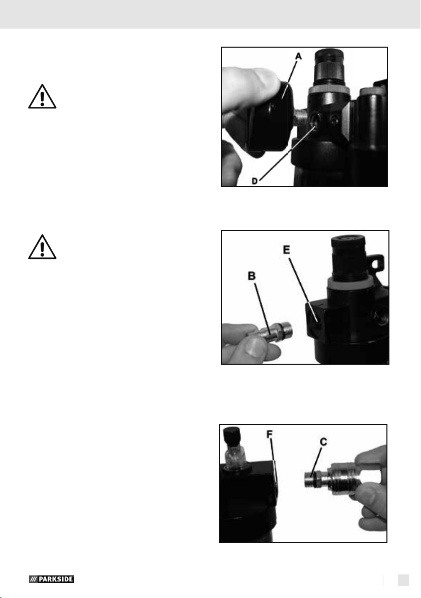
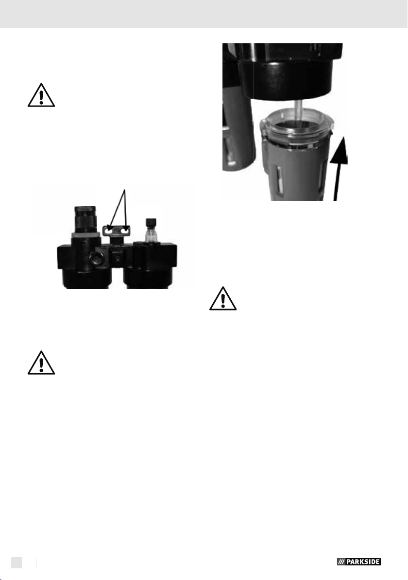
Screw the threaded barbed fitting (B) manually
in the illustrated position (E) of the filter unit.
Before starting up
Connect the pressure gage and the connection
pieces
Wind the Teflon band (not enclosed) around
the threads of the pressure gauge(A), the
threaded barbed fitting (B) (not enclosed) and
the quick coupling (C) (not enclosed).
Subsequently screw the pressure gauge (A)
manually in the illustrated position (D) of the
filter unit.
Screw the quick-coupling (C) manually in the
illustrated position (F) of the oil-mist unit.
GB/IE/NI 9
Installation
Achtung:
Zur Minimierung von potenti-
ell auftretenden Verletzungen
oder Schäden ist es erforder-
lich, die Wartungseinheit vor der ers-
ten Inbetriebnahme an einer geeigne-
ten Wand zu montieren� Achten Sie
auf eine stabile und horizontale Mon-
tage der Druckluft Wartungseinheit�
• Benutzen Sie zur Wandmontage
die Befestigungseinheit zur Markierung
an der Wand und zur Verschraubung
mit passendem Verbindungsmaterial�
Befüllen bzw� Lösen des Behälters die
Wartungseinheit von der Druckluftquel-
le getrennt wurde�
• Entfernen Sie die Verschraubung
des Ölbehälters und befüllen Sie die-
sen mit passendem Kompressoren-Öl
soweit, bis die max� Markierung er-
reicht ist�
• Im Anschluss daran, drehen Sie den
Behälter nur manuell (ohne Werkzeug)
mit der Hand fest�
Inbetriebnahme
Verbinden Sie die Druckluft
Wartungseinheit mit der Druck-
luftquelle
Achten Sie darauf, dass die
angeschlossene Druckluftlei-
tung sauber und ölfrei ist, um
die Druckluft Wartungseinheit auch
Installation / Inbetriebnahme
Installation / Inbetriebnahme
Before starting up/ Installation / Starting up
Installation
Attention:
To minimise potential injury or damage,
the maintenance unit must be installed on
a suitable wall before first commissioning. Ensure a stable and
pneumatic maintenance unit.
Use the attachment unit to mark the wall for
wall installation and for screwing on with
matching connection material.
horizontal assembly of the
Filling the oil mist unit
Ensure that the maintenance unit has
been separated from the compressed air
source before filling or releasing the
container.
Remove the screws of the oil container and fill
it with the matching compressor oil until the
max. mark has been reached.
Subsequently tighten the container only
manually (without tools).
Starting up
Connect the pneumatic maintenance unit
to the compressed air source
Ensure that the connected compressed air
line is clean and oil-free in order to
properly use the compressed air
maintenance unit. Further ensure that the pneumatic
system is depressurised. To minimise pressure loss,
it is beneficial if the compressed air lines are kept
as short as possible.
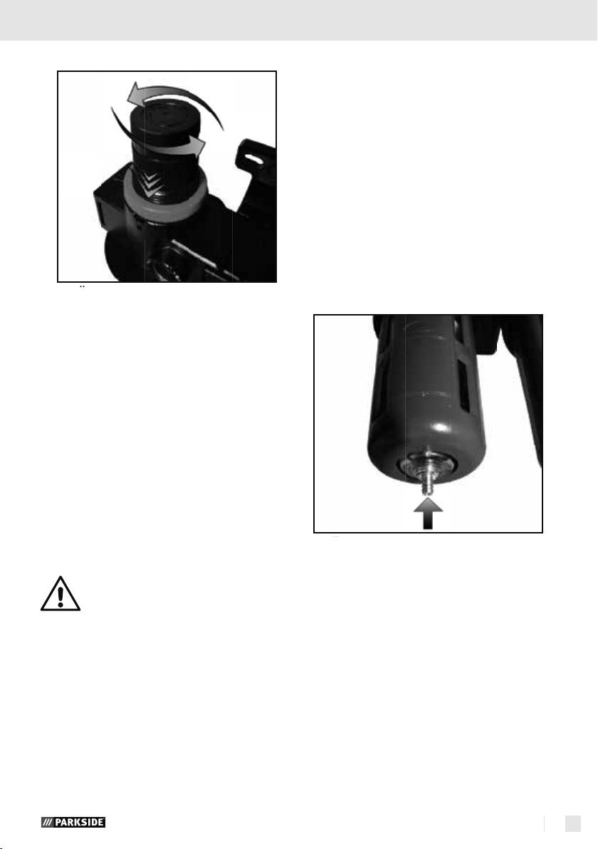
First, turn counter-clockwise to set the com-
pressed air controller to the lowest possible
level. The desired settings will be assumed by
pushing down the compressed air controller.
Connect the compressed air supply line of the
tool to be connected to the right side (output) of
the maintenance unit (see figure on the right). A
triangle "" on the surface of the device indicates the flow direction of the compressed air.
Connect the compressed air supply of the
compressed air source on the left (input) of the
maintenance unit (directly at the input, the surface has a triangle "", that indicates the flow
direction of the compressed air).
GB/IE/NI10
mierung von Druckverlusten, ist es vor-
teilhaft, die Druckluftleitungen mög-
lichst kurz zu halten�
• Stellen Sie zuerst durch Drehen ge-
gen den Uhrzeigersinn, den Druckluft-
regler auf die niedrig möglichste Stufe
ein� Die gewünschten Einstellungen
werden übernommen, indem Sie den
Druckluftregler nach unten drücken�
• Schließen Sie die Druckluftzuleitung
des anzuschließenden Werkzeuges
auf der rechten Seite (Ausgang) der
Wartungseinheit an (siehe Bild rechts)�
Ein Dreieck „ “ auf der Oberfläche
des Gerätes zeigt die Fließrichtung der
Druckluft an�
• Schließen Sie die Druckluftzuleitung
der Druckluftquelle auf der linken Seite
(Eingang) der Wartungseinheit an (di-
rekt am Eingang befindet sich auf der
Oberfläche ein Dreieck „ “, welches
die Fließrichtung der Druckluft angibt)�
Druck erzeugt�
• Einstellen des Arbeitsdrucks
Nach Verknüpfung der Wartungsein-
heit mit einer Druckluftquelle (siehe
oben), können Sie den gewünschten
Betriebsdruck mittels des Druckreglers
einstellen�
• Durch drehen gegen den Uhrzei-
gersinn wird der Druck reduziert und
durch drehen im Uhrzeiger sind wird
der Druck erhöht�
• Entnehmen Sie den eingestellten
Druck an der Manometeranzeige�
Hinweis: Achten Sie darauf,
dass der maximal mögliche
Betriebsdruck der Wartungs-
einheit und des eingesetzten Druckluft-
werkzeugs nicht überschritten wird�
• Filtereinheit
Die Filtereinheit ist mit dem Druckregler
verknüpft� Der maximale Arbeitsdruck
beträgt 8 bar und der Betriebsdruck
ist von 0,5 bis 8 bar regulierbar� Die
Filtereinheit wird zum Filtern von Kon-
densat eingesetzt und speichert das
Kondensat im Filterbehälter�
Den Füllstand des Kondensats können
Sie durch die transparenten Sichtflä-
chen überprüfen� Das gespeicherte
Kondensat kann über das Ablassventil
abgelassen werden�
• Kondensatablass mittels des
Inbetriebnahme
dung der Filtereinheit ohne montierten
Behälter ist untersagt�
• Um das gespeicherte Kondensat
aus dem Behälter zu entleeren, ver-
wenden Sie einen entsprechenden
Behälter� Durch leichte Betätigung des
Ablassventils (6), öffnet sich dieses und
das Kondensat kann abgelassen wer-
den�
zu steigern�
• Das integrierte Schauglas ermög-
licht einen ständigen Überblick auf die
gefilterte Druckluft�
• Um Öl nachzufüllen, drehen Sie
die Schraube (B) mit einem geeigneten
Inbusschlüssel ab� Befüllen Sie den Be-
hälter mittels eines passenden Trichters
und drehen Sie die Schraube danach
wieder mit dem Schlüssel fest�
Fehlererkennung und Behebung
Fehler Ursachen Lösung
Die Schmie-
rung ist nicht
ausreichend
Öldurchlass-
schraube
ist zu fest in
Richtung („-“)
zugedreht�
Steigern Sie
die Schmie-
rung (siehe
oben)�
Die Druck-
luftölmen-
ge ist zu
Gießen Sie
mehr Öl in
den Ölbehäl-
Reinigung und Wartung
Before commissioning of the maintenance unit,
check the compressed air flow direction with
the mark "" on the surface. If the setting is
not correct, the pressure generated will not be
correct.
Setting the working
pressure
After linking the maintenance unit to a compressed
air source (see above), you can set the desired
operating pressure with the pressure controller.
Turning counter-clockwise reduces the pressure,
and turning clockwise increases the pressure.
Read the set pressure at the pressure gauge
display.
Note:
Ensure that the maximum possible operating pressure of the maintenance unit and
the pneumatic tool is not exceeded.
Filter unit
The filter unit is linked to the pressure controller.
The maximum working pressure is 8 bar and the
operating pressure can be adjusted from 0.5 to
8 bar. The filter unit is used to filter condensate and
stores the condensate in the filter tank.
You can check the condensate fill level through the
Starting up
transparent sight windows. The stored condensate
can be drained via the drain valve.
Condensate drain via the
drain valve
Ensure horizontal installation of the maintenance
unit so that the condensate can be stored horizontally in the tank as well. The filter unit must not be
used without the tank installed.
Use a matching tank in order to drain the
stored condensate from the tank. Slight operation of the drain valve (6) opens it and lets the
condensate drain.
Oil mister unit
The oil mister unit is connected to the filter unit. It
has the function of oiling the filtered compressed air
that is transported towards the compressed air tool.
You can check the fill level of the oil tank
(integrated into the oil mister unit) through the
transparent sight windows. Use only matching oil
for this maintenance unit (see above).
Turn the oil drain screw (A) that is installed
on the sight glass clockwise ("–"), in order
to reduce the required volume of oil. Turn it
counter-clockwise ("+") to increase the volume
GB/IE/NI 11

... / Cleaning and maintenance / Warranty and service information
of oil.
The integrated sight window permits continuous
overview of the filtered compressed air.
To top up oil, turn the screw (B) down with
a suitable socket wrench. Fill the tank with a
matching hopper and tighten the screw again
with the wrench.
Troubleshooting
Faults Causes Solution
The lubrication
is not sufficient
The operating
pressure of the
compressed
air is too low.
The oil passage screw it
tightened too
far in direction
("–").
The compressed air
volume is too
low, i.e. below
the minimum
fill level.
The pressure
controller
is tightened
too far
(see above).
Increase
lubrication
(see above).
Pour more oil
into the oil
tank. Observe
the maximum
fill level.
Increase the
pressure
(see above).
Cleaning and maintenance
Note:
The pneumatic maintenance unit must be
regularly serviced and overhauled for
proper function and for compliance with the safety
requirements. Improper and wrong operation may
cause failures and damage to the device.
Never use any sharp and/or scraping cleaning
agents or solvents. They may damage the plastic parts of the pneumatic maintenance unit.
Make sure that no water can enter inside the
oiler.
Ensure that the housing and the inside of the
pneumatic maintenance unit remains dust- and
dirt-free. For this, regularly rub the pneumatic
maintenance unit with a clean cloth.
Clean the pneumatic maintenance unit and the
connections with a moist cloth at regular intervals.
Drain the pneumatic maintenance unit's tank
at regular intervals. For this, press in the metal
pin at the bottom and let the condensate drain.
Note that the pneumatic maintenance unit must
be depressurised for safety.
Warranty and service
information
Warranty from Creative Marketing
Consulting GmbH
Dear Customer,
The warranty for this device is 3 years from the
date of purchase. In the event of product defects,
you have legal rights against the retailer of this
product. Your statutory rights are not affected in
any way by our warranty conditions, which are
described below.
Warranty conditions
The warranty period begins on the date of purchase. Please retain the original sales receipt. This
document is required as your proof of purchase.
Should this product show any defect in materials
or manufacture within 3 years from the date of
purchase, we will repair or replace it – at our
discretion – free of charge. To claim against this
warranty, you must present the defective device
and your purchase receipt within the 3-year period,
and include a brief written description of the nature
of the defect and the date it occurred. If the defect
is covered by our warranty, we will repair and
return your product or send you a replacement.
The original warranty period is not extended when
a device is repair or replaced.
Extent of warranty
The device has been manufactured according to
strict quality guidelines and meticulously examined
GB/IE/NI12
 Loading...