


Panasonic TH-55LF6W, TH-55LF60W, TH-42LF60W, TH-47LF6W, TH-47LF60W User Manual
...Operating Instructions
FULL HD LCD Display
Model No.
TH-42LF6W TH-42LF60W TH-47LF6W TH-47LF60W TH-55LF6W TH-55LF60W
|
Before connecting, operating or adjusting this product, |
|
|
|
|
|
|
|
|
English |
|
|
|
|
|
please read these instructions completely. |
|
|
|
|
Please keep this manual for future reference. |
|
|
|

Dear Panasonic Customer
Welcome to the Panasonic family of customers. We hope that you will have many years of enjoyment from your new LCD Display.
! !
Visit our Panasonic Web Site http://panasonic.net
Table of Contents
Important Safety Notice ............................................ |
3 |
|
Safety Precautions .................................................... |
4 |
|
Accessories ............................................................... |
|
7 |
Accessories Supplied ............................................. |
7 |
|
Remote Control Batteries ....................................... |
7 |
|
Ceiling Suspension ................................................... |
8 |
|
Connections............................................................... |
|
9 |
|
...................... |
9 |
Video equipment connection ................................ |
10 |
|
AUDIO OUT connection ........................................ |
11 |
|
HDMI connection.................................................. |
12 |
|
VIDEO, COMPONENT and RGB IN connection .. |
13 |
|
DVI-D IN, DVI-D OUT connection ........................ |
14 |
|
PC Input Terminals connection............................. |
15 |
|
SERIAL Terminals connection .............................. |
16 |
|
IR IN / IR OUT Terminals connection ................... |
17 |
|
|
|
|
Terminal................................................................ |
|
18 |
Power On / Off.......................................................... |
|
19 |
Selecting the input signal....................................... |
21 |
|
Basic Controls ......................................................... |
|
22 |
ASPECT Controls .................................................... |
24 |
|
Digital Zoom............................................................. |
|
25 |
On-Screen Menu Displays ...................................... |
26 |
|
Adjusting Pos. /Size ................................................ |
27 |
|
Picture Adjustments................................................ |
29 |
|
Advanced settings ................................................ |
30 |
|
Sound Adjustment................................................... |
31 |
|
PRESENT TIME Setup / Set up TIMER................... |
32 |
|
PRESENT TIME Setup......................................... |
32 |
|
Set up TIMER....................................................... |
33 |
|
Screensaver (For preventing image retention)..... |
34 |
|
Setup of Screensaver Time .................................. |
35 |
|
Wobbling .................................................................. |
|
35 |
No activity power off ............................................... |
36 |
|
ECO Mode settings.................................................. |
37 |
|
Customizing the Input labels.................................. |
38 |
|
Selecting the On-Screen Menu Language............. |
39 |
|
Customizing the On-Screen Menu Display ........... |
39 |
Setup for MULTI DISPLAY....................................... |
40 |
How to setup MULTI DISPLAY............................. |
40 |
ID Remote Control Function................................. |
41 |
Setup for Input Signals ........................................... |
42 |
Component / RGB-in select.................................. |
42 |
YUV / RGB-in select............................................. |
42 |
Signal menu ......................................................... |
43 |
3D Y/C Filter......................................................... |
43 |
Colour system ...................................................... |
44 |
Cinema reality ...................................................... |
44 |
XGA Mode ............................................................ |
44 |
Noise reduction .................................................... |
45 |
Sync ..................................................................... |
45 |
HDMI Range......................................................... |
45 |
Input signal display............................................... |
46 |
Network Setup ......................................................... |
47 |
Options Adjustments .............................................. |
50 |
Input Search ......................................................... |
52 |
RS-232C/LAN Information Timing ........................ |
53 |
Using Network Function ......................................... |
54 |
Network Connection ............................................. |
54 |
(connecting with a |
55 |
twisted pair cable transmitter)....................... |
|
Command Control ................................................ |
56 |
PJLink™ Protocol................................................. |
56 |
Using Web Browser Control................................... |
57 |
Before Using Web Browser Control ..................... |
57 |
Access from Web Browser ................................... |
57 |
Display Control (BASIC CONTROL/OPTION CONTROL |
|
Screen)............................................................................... |
58 |
!"# $ % & ' $ $ * ... |
59 |
Password Setting (Password Setup Screen) ....... |
59 |
Crestron Connected™ page................................. |
60 |
Troubleshooting ...................................................... |
62 |
Applicable input signals ......................................... |
64 |
Shipping condition.................................................. |
66 |
......................................... |
67 |
Trademark Credits
+ VGA is a trademark of International Business Machines Corporation.
+ Microsoft®, Windows®, Windows Vista®: ® are the registered trademarks or trademarks of Microsoft Corporation in the United States and/or other countries.
+ Macintosh, Mac, Mac OS, OS X and Safari are the trademarks of Apple Inc. registered in the United States and other countries.
+ SVGA, XGA, SXGA and UXGA are registered trademarks of the Video Electronics Standard Association.
+ ; < : ; < : ; = < > ' ' > ; < LLC in the United States and other countries.
+ RoomView, Crestron RoomView and Fusion RV are registered trademarks of Crestron Electronics, Inc, and Crestron Connected is the trademark of Crestron Electronics, Inc.
Even if no special notation has been made of company or product trademarks, these trademarks have been fully respected.
2
Important Safety Notice
WARNING
1) splashing.
!" # !# !" $ # % # !
?* @ ': @ @ K @ K # > @ Q service personnel.
3)Do not remove the earthing pin on the power plug. This apparatus is equipped with a three pin earthing-type& K & Z = Z & K > Z > K > Z the plug into the outlet, contact an electrician.
Do not defeat the purpose of the earthing plug.
4)To prevent electric shock, ensure the earthing pin on the AC cord power plug is securely connected.
CAUTION
> @ & @ Z > > K
[ > & Z @ & input signals could cause the picture and sound to wobble or cause interference such as noise to appear.
@ Z > : ' & Z > > K
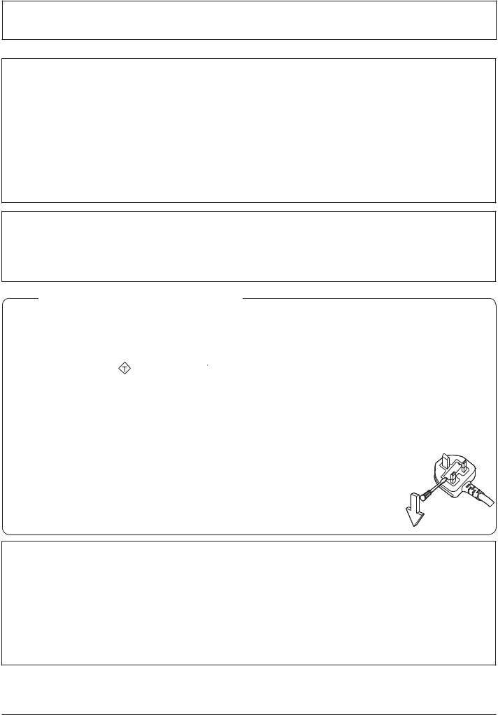
IMPORTANT: THE MOULDED PLUG
&'* +',* :&; + <=;: ; *;: >; &'=='?@$J ;K Q:*;&,==+!
This display is supplied with a moulded three pin mains plug for your safety and convenience. A 10 amp fuse isK $ > : > > \] amps and that it is approved by ASTA or BSI to BS1362.
Check for the ASTA mark ASA or the BSI mark  on the body of the fuse.
> @ > @ : Z & > K > Z the fuse cover the plug must not be used until a replacement cover is obtained. A replacement fuse cover can be purchased from your local Panasonic dealer.
Do not cut off the mains plug.
Z Z > & ZK
The supplied mains lead and moulded plug are designed to be used with this display to avoid interference and for your safety. 
> ' Z : Z Q K
If the plug or mains lead becomes damaged, purchase a replacement from an authorized dealer.
WARNING : — THIS DISPLAY MUST BE EARTHED.  How to replace the fuse. Open the fuse compartment with a screwdriver and replace the fuse.
IMPORTANT INSTALLATION INFORMATION
> Z > Z : Z ^ > K < Z injuries, particularly to children, can be avoided by taking simple precautions such as:
+ Using cabinets or stands recommended by the manufacturer of the display. + Only using furniture that can safely support the display.
+ Ensuring the display is not overhanging the edge of the supporting furniture.
+ Z > %> : ' * & > and the display to a suitable support.
+ Not standing the displays on cloth or other materials placed between the display and supporting furniture. + Educating children about the dangers of climbing on furniture to reach the display or its controls.
Note:
+ Z K > Z Z > : screen. However, it will disappear after a while.
3

Safety Precautions
WARNING
Setup
This LCD Display is for use only with the following optional accessories. Use with any other type of optional accessories may cause instability which could result in the possibility of injury.
(All of the following accessories are manufactured by Panasonic Corporation.)
+ Pedestal ............................................................. |
TY-ST42P50 |
(for 42 and 47 inch models) |
|
TY-ST58P20 |
(for 55 inch models) |
& Z ' Q Z = K
$ ' ^ > Z & & K & Z > Z K unneeded small parts and other objects, including packaging materials and plastic bags/sheets to prevent them from being played with by young children, creating the potential risk of suffocation.
# X edge of the base.
+ The Display may fall off or tip over.
Do not place any objects on top of the Display.
+ > & Z > ` : = Z & electric shock. If any foreign objects get inside the Display, please consult your local Panasonic dealer.
Transport only in upright position!
+ Transporting the unit with its display panel facing upright or downward may cause damage to the internal circuitry.
\ # # # cloths and curtains.
& X ]
= X ^_ X ` # # X X !
Cautions for Wall Installation
+ Wall installation should be performed by an installation professional. Installing the Display incorrectly may lead to an` ZK [ K
+ When installing the Display vertically, be sure to install the power indicator onto the bottom of the Display.
Caution for Ceiling Suspension
+ Ceiling suspension should be performed by an installation professional. Installing the Display incorrectly may lead to an accident that results in death or serious injury.
!
+ > : Q Z Z @ @ >> K
4

Safety Precautions
When using the LCD Display
qq_x q{_\ :Q `_%|_> !
Do not cover the ventilation holes.
+ Z Z @ : & ZK
Do not stick any foreign objects into the Display.
+ Z x ` @ Z:'K
Do not remove the cover or modify it in any way.
+ High voltages which can cause severe electric shocks are present inside the Display. For any inspection, adjustment and repair work, please contact your local Panasonic dealer.
Ensure that the mains plug is easily accessible.
An apparatus with CLASS I construction shall be connected to a mains socket outlet with a protective earthing connection.
Do not use any power supply cord other than that provided with this unit.
+ Z ' K
Securely insert the power supply plug as far as it will go.
+ > > Z : Z & K > & socket is loose, they shall not be used.
Do not handle the power supply plug with wet hands.
+ Doing so may cause electric shocks.
# ! ? # # # !
+ : ' Z : @Z ` > : : Z ` : & : @ Z K Z 'K > & damaged, have it repaired at your local Panasonic dealer.
@X # X X X wall outlet.
X X !
If problems occur during use
@X # " X # XX !
+ > Z Z : ' K > ' ' has stopped, contact your local Panasonic dealer so that the necessary repairs can be made. Repairing the Display Z > Z : @ K
@X X #} X X # # disconnect the power supply plug immediately.
+ Z : & K Z { > Z be made.
5

Safety Precautions
CAUTION
When using the LCD Display
# X #} X !
+ Heated air comes out from the ventilation holes at the top of Display will be hot. Do not bring your hands or face, or objects which cannot withstand heat, close to this port, otherwise burns or deformation could result.
Be sure to disconnect all cables before moving the Display.
+ > Z @ & > : Z : electric shock could result.
Disconnect the power supply plug from the wall socket as a safety precaution before carrying out any cleaning.
+ Electric shocks can result if this is not done.
Clean the power cable regularly to prevent it becoming dusty.
+ > & : Z : & K Pull the power cord plug out from the wall outlet and wipe the mains lead with a dry cloth.
Do not burn or breakup batteries.
+ | @ : ' K
Cleaning and maintenance 
The front of the display panel has been specially treated. Wipe the panel surface gently using only a cleaning
X xX !
+ If the surface is particularly dirty, wipe with a soft, lint-free cloth which has been soaked in pure water or water in which neutral detergent has been diluted 100 times, and then wipe it evenly with a dry cloth of the same type until the surface is dry.
+ > > & ` : & > Z become damaged. Furthermore, avoid contact with volatile substances such as insect sprays, solvents and thinner, otherwise the quality of the surface may be adversely affected.
@X # # X !
+ If the cabinet is particularly dirty, soak the cloth in water to which a small amount of neutral detergent has been added and then wring the cloth dry. Use this cloth to wipe the cabinet, and then wipe it dry with a dry cloth.
+ Do not allow any detergent to come into direct contact with the surface of the Display. If water droplets get inside the unit, operating problems may result.
+ Avoid contact with volatile substances such as insect sprays, solvents and thinner, otherwise the quality of the cabinet surface may be adversely affected or the coating may peel off. Furthermore, do not leave it for long periods in contact with articles made from rubber or PVC.
Usage of a chemical cloth
+ Do not use a chemical cloth for the panel surface.
+ Follow the instructions for the chemical cloth to use it for the cabinet.
6
Accessories
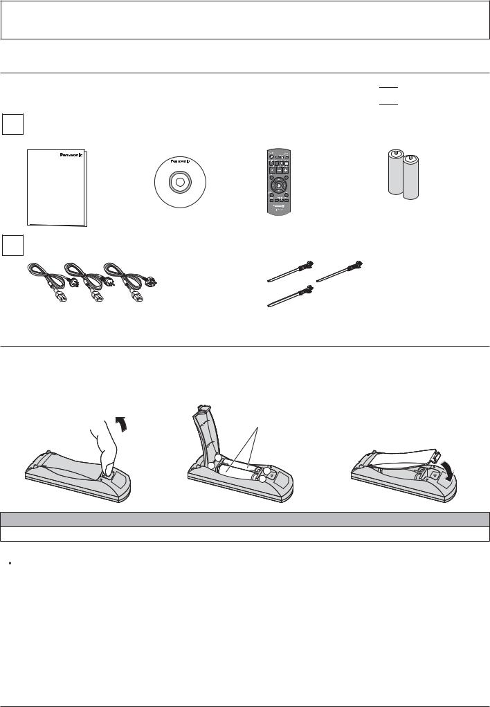
Accessories Supplied
Check that you have the Accessories and items shown 

Operating instruction |
|
CD-ROM |
|
Remote control |
|
Batteries for the remote |
||||||
book |
|
(Operating |
|
transmitter |
|
control transmitter |
||||||
|
|
|
|
|
|
instruction) |
|
N2QAYB000691 |
|
(R6 (UM3) Size × 2) |
||
|
|
|
|
|
|
|
|
|
|
|
|
|
|
|
|
|
|
|
|
|
|
|
|
|
|
|
|
|
|
|
|
|
|
|
|
|
|
|
|
|
|
|
|
|
|
|
|
|
|
|
|
AC cord |
|
Clamper × 3 |
|
|
|
Remote Control Batteries
Requires two R6 batteries.
1.Pull and hold the hook, then open the battery cover.
2. Insert batteries - note correct |
3. Replace the cover. |
polarity (+ and -).
“R6 (UM3)” size
- |
+ |
+ |
|
- |
Helpful Hint:
For frequent remote control users, replace old batteries with Alkaline batteries for longer life.
 Precaution on battery use
Incorrect installation can cause battery leakage and corrosion that will damage the remote control transmitter. Disposal of batteries should be in an environment-friendly manner.
Observe the following precautions:
1.Batteries should always be replaced as a pair. Always use new batteries when replacing the old set.
2.Do not combine a used battery with a new one.
3.Z Z % • €• ‚ & € ' ‚*K
4.Do not attempt to charge, short-circuit, disassemble, heat or burn used batteries.
5.Battery replacement is necessary when the remote control acts sporadically or stops operating the Display.
6.Do not burn or breakup batteries.
| @ : ' K
7

Ceiling Suspension
You can install the Display by attaching commercially available eyebolts (M10) to it and suspending it from the ceiling, etc. (TH-55LF6W, TH-55LF60W)
Eyebolt mounting positions (for horizontal installation)
Note:
+ Suspension and installation should be performed by an installation professional.
+ Do not install it using only one eyebolt.
+ When the Display is installed horizontally or vertically, make sure to place the power Indicator side down.
+ Install the wire along the vertical side when suspending the Display.
Eyebolt mounting positions (for vertical installation)
8
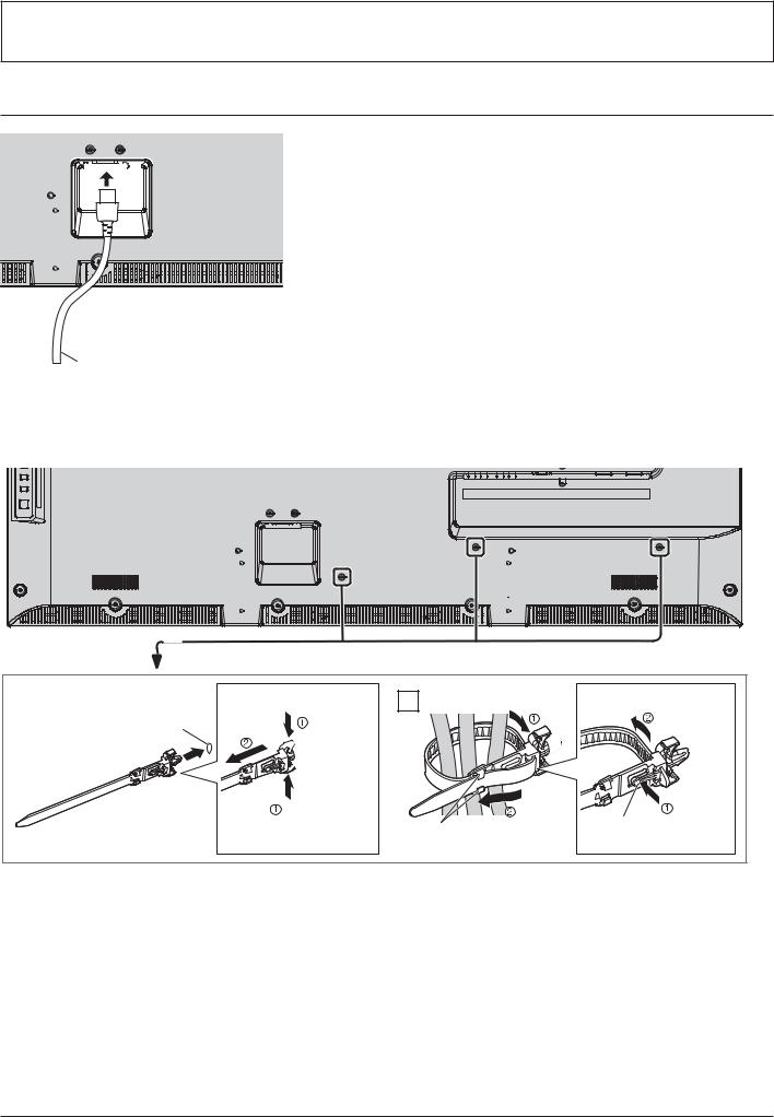
Connections
:Q # X
AC cord (accessory)
Using the clamper
$ Z & Q K
1 |
Attach the clamper |
To remove from the unit: |
hole
 snaps
snaps
Insert the clamper |
|
|
pushing both |
||
in a hole. |
||
side snaps |
||
|
2 Bundle the cables |
To loosen: |
|
Set the |
|
|
|
|
knob |
pushing |
||
hooks |
tip in the |
|||
the knob |
||||
|
||||
|
hooks |
|
|
9

Connections
Video equipment connection
@* @$@* ',
To control multiple display with one
remote control, connects other display


 from this IN/OUT port.
> @ >
unit will send to the second unit. (see page 17)
;*@:= @$;*@:= ',
SERIAL Input/Output Terminal
Control the Display by connecting to PC. (see page 16)
=:$@J@ := =@$‚
terminal network to control the Display.
Alternatively, connect to a device that
sends video and audio signals via the
K (see page 18, 54, 55)
AUDIO IN (VIDEO)
Connect the audio output of a device connected to VIDEO IN.
(see page 13)
AUDIO IN (COMPONENT / RGB)
Connect the audio output of a device connected to COMPONENT/RGB IN. (see page 13)
AUDIO IN (DVI-D / PC)
Connect the audio output of a device connected to DVI-D IN, PC IN.
(see page 14, 15)
AUDIO OUT
Connect to sound equipment (see page 11)
|
|
|
|
|
|
|
|
|
|
|
|
|
|
|
|
|
|
|
|
|
|
|
|
|
|
|
|
|
|
|
|
|
|
|
|
|
|
|
|
|
|
|
|
|
|
|
|
|
|
|
|
|
|
|
|
|
|
|
|
|
|
|
|
|
|
|
|
|
|
|
|
|
|
|
|
|
|
|
|
|
|
|
|
|
|
|
|
|
|
|
|
|
|
|
|
|
|
|
|
|
|
|
|
|
|
|
|
|
|
|
|
|
|
|
|
|
|
|
|
|
|
|
|
|
|
|
|
|
|
|
|
|
|
|
|
|
|
|
|
|
|
|
|
|
|
|
|
|
|
|
|
|
|
|
|
|
|
|
|
|
|
|
|
|
|
|
|
|
|
|
|
|
|
|
|
|
|
|
|
|
|
|
|
|
|
|
|
|
|
|
|
|
|
|
|
|
|
|
|
|
|
|
|
|
|
|
|
|
|
|
|
|
|
|
|
|
|
|
|
|
|
|
|
|
|
|
|
|
|
|
|
|
|
|
|
|
|
|
|
|
|
|
|
|
|
|
|
|
|
|
|
|
|
|
|
|
|
|
|
|
|
|
|
|
|
|
|
|
|
|
|
|
|
|
|
|
|
|
|
|
|
|
|
|
|
|
|
|
|
|
|
|
|
|
|
|
|
|
|
|
|
|
|
|
|
|
|
|
|
|
|
|
|
|
|
|
|
|
|
COMPONENT/RGB IN |
|
VIDEO IN (VIDEO) |
|
PC IN |
|
|
AV IN |
|
\@x @$\@x ', |
||||||||||||||||||
|
|
R |
|
B |
|
Composite Video |
|
PC Input |
|
|
>€@ ^ >€@ q |
|
DVI-D Input/Output |
|||||||||||||||
|
(P |
%* < %• +%J" |
|
Input Terminal |
|
Terminal |
|
|
|
Terminal |
||||||||||||||||||
|
Component/RGB Video Input |
|
|
|
|
HDMI Input Terminal |
|
|||||||||||||||||||||
|
Terminal (see page 13) |
|
(see page 13) |
|
(see page 15) |
|
|
(see page 12) |
|
(see page 14) |
||||||||||||||||||
|
|
|
|
|
|
|
|
|
|
|
|
|
|
|
|
|
|
|
|
|
|
|
|
|
|
|
|
|
10
Connections
AUDIO OUT connection
Note:
+ [ " "[ @ > Q K + Additional equipment and cables shown are not supplied with this set.
Stereophonic sound code
audio equipment
Stereo mini plug (M3)
line-in
11
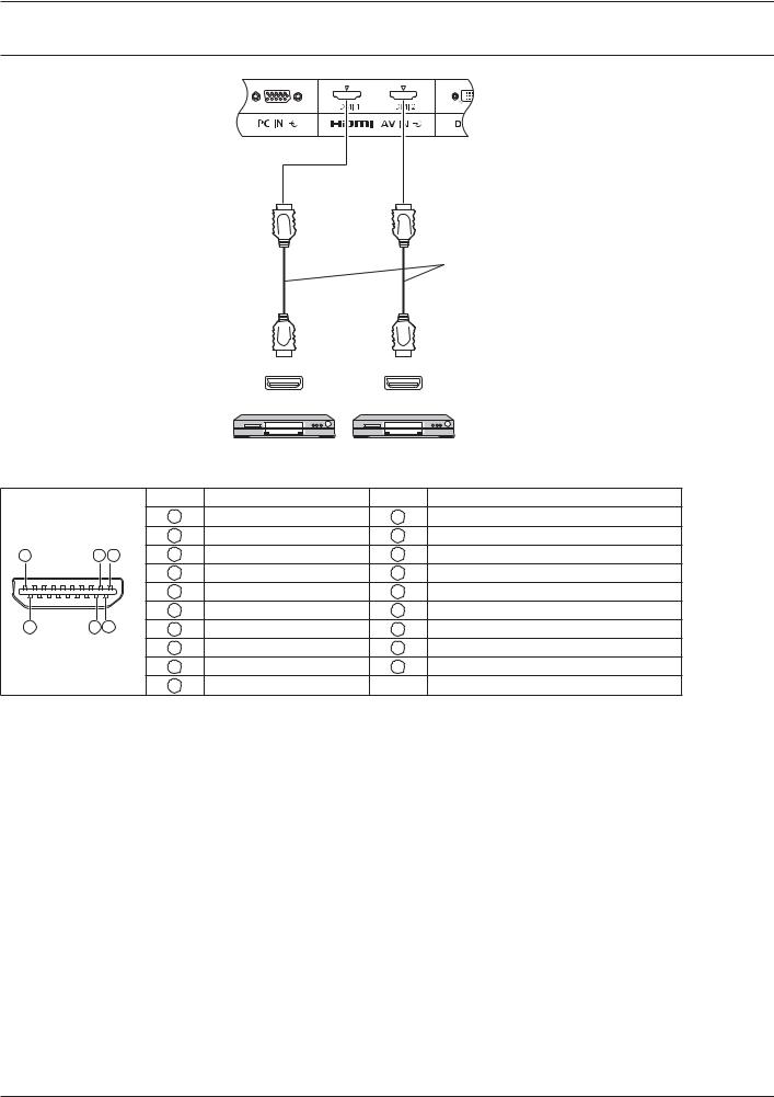
Connections
HDMI connection
HDMI cable
HDMI |
HDMI |
AV OUT |
AV OUT |
DVD player DVD player
[Pin assignments and signal names]
|
|
|
Pin No. |
Signal Name |
Pin No. |
Signal Name |
|
|
|
1 |
T.M.D.S. Data2 + |
11 |
T.M.D.S. Clock Shield |
|
|
|
2 |
T.M.D.S. Data2 Shield |
12 |
T.M.D.S. Clock – |
19 |
3 |
1 |
3 |
T.M.D.S. Data2 – |
13 |
CEC |
|
|
|
4 |
T.M.D.S. Data1 + |
14 |
Reserved (N.C. on device) |
|
|
|
5 |
T.M.D.S. Data1 Shield |
15 |
SCL |
|
4 |
2 |
6 |
T.M.D.S. Data1 – |
16 |
SDA |
18 |
7 |
T.M.D.S. Data0 + |
17 |
DDC/CEC Ground |
||
|
|
|
8 |
T.M.D.S. Data0 Shield |
18 |
+5 V DC |
|
|
|
9 |
T.M.D.S. Data0 – |
19 |
Hot Plug Detect |
|
|
|
10 |
T.M.D.S. Clock + |
|
|
Note: |
|
|
|
|
|
|
+ Additional equipment and HDMI cable shown are not supplied with this set.
12

Connections
\@ ;' Q'€<'$;$*J• @$
Note:
+ Additional equipment, cables and adapter plugs shown are not supplied with this set.
DVD Player |
VCR |
|
VIDEO OUT |
AUDIO OUT |
|
|
L |
R |
RCA-BNC
Adapter plug
RCA-BNC |
Adapter plug |
Y PB PR OUT |
L |
R |
RGB OUT |
AUDIO OUT |
|
Computer |
RGB Camcorder |
DVD Player |
Notes:
+ Change the “Component/RGB-in select” setting in the “Setup” menu to “Component” (when Component signal connection) or “RGB” (when RGB signal connection). (see page 42)
+ Accepts only RGB signals from COMPONENT/RGB IN terminal with “Sync on G”.
13

Connections
\@x @$\@x ',
PC with DVI-D video out
Shared with PC IN. 
DVI-video cable (Within 5 m)
Stereo mini plug (M3)
Daisy chain connection
When using the multi display, multiple LCD Displays can be daisy chained.
First LCD Display |
Second LCD Display |
PC with DVI-D video out
|
|
Third and |
|
* |
* |
subsequent |
|
LCD displays |
|||
* DVI-video cable |
|
Notes:
+ Up to 10 displays can be connected with a daisy chain, but the number of the connected displays may be limited by a cable, signal or equipment to use.
+ HDCP signals can be processed, with up to 8 displays connected via a daisy chain connection.
DVI-D Input Connector Pin Layouts: |
Pin No. |
Signal Name |
Pin No. |
Signal Name |
|
1 |
T.M.D.S. Data2 – |
13 |
— |
|
2 |
T.M.D.S. Data2 + |
14 |
+5 V DC |
|
3 |
T.M.D.S. Data2 Shield |
15 |
Ground |
|
4 |
— |
16 |
Hot Plug Detect |
|
5 |
— |
17 |
T.M.D.S. Data0 – |
Connection port view |
6 |
DDC Clock |
18 |
T.M.D.S. Data0 + |
|
7 |
DDC Data |
19 |
T.M.D.S. Data0 Shield |
|
8 |
— |
20 |
— |
|
9 |
T.M.D.S. Data1 – |
21 |
— |
|
10 |
T.M.D.S. Data1 + |
22 |
T.M.D.S. Clock Shield |
|
11 |
T.M.D.S. Data1 Shield |
23 |
T.M.D.S. Clock + |
|
12 |
— |
24 |
T.M.D.S. Clock – |
Note: |
|
|
|
|
+ Additional equipment and cables shown are not supplied with this set.
14
Connections
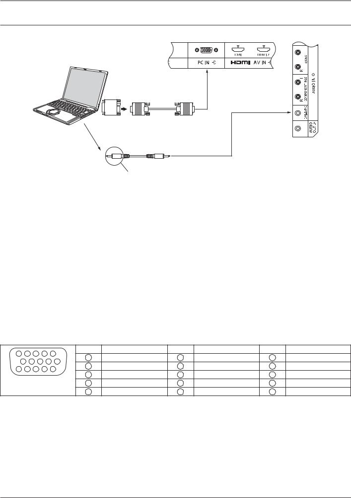
PC Input Terminals connection
(Female)
COMPUTER
Conversion adapter |
|
(if necessary) |
(Male) |
|
RGB |
|
Shared with DVI-D IN. |
|
Mini D-sub 15p |
Audio
Stereo mini plug (M3)
Connect a cable which matches
the audio output terminal on the computer.
Notes:
+ Computer signals which can be input are those with a horizontal scanning frequency of 30 to 110 kHz and vertical> Q Z > †‡ \?] ;^K %; & @ : & Z Z > \:?]] lines.)
+ Z > \:††] ˆ \:]‡] & €†•‰‚: \:Š?] ˆ \:]‡] & €\‹•Š‚K > Z : Z& & > ZK
+ The PC input terminals are DDC2B-compatible. If the computer being connected is not DDC2B-compatible, you will need to make setting changes to the computer at the time of connection.
+ Some PC models cannot be connected to the set.
+ There is no need to use an adapter for computers with DOS/V compatible Mini D-sub 15P terminal.
+ |
& |
> ZK |
+ Additional equipment and cables shown are not supplied with this set. |
||
+ |
^ |
@ > Q > { & @ & |
|
frequency range. |
|
Signal Names for Mini D-sub 15P Connector
5 |
|
4 |
3 |
2 |
1 |
Pin No. Signal Name |
Pin No. Signal Name |
Pin No. Signal Name |
||||
|
1 |
R |
6 |
GND (Ground) |
11 |
NC (not connected) |
||||||
10 |
9 |
8 |
7 |
6 |
||||||||
2 |
G |
7 |
GND (Ground) |
12 |
SDA |
|||||||
15 |
14 |
13 |
12 |
11 |
||||||||
3 |
B |
8 |
GND (Ground) |
13 |
HD/SYNC |
|||||||
Pin Layout for PC Input |
||||||||||||
4 |
NC (not connected) |
9 |
+5 V DC |
14 |
VD |
|||||||
|
|
Terminal |
|
5 |
GND (Ground) |
10 |
GND (Ground) |
15 |
SCL |
|||
15
Connections
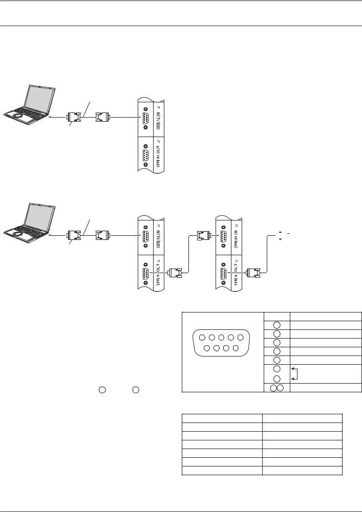
SERIAL Terminals connection
The SERIAL terminal is used when the Display is controlled by a computer.
Note:
+ To use serial control for this unit, make sure to set the “Control I/F Select” in the “Network Setup” menu to “RS-232C (Serial)”. (see page 47)
COMPUTER
(Male)
RS-232C Straight cable
(Female)
D-sub 9p
In addition, a particular LCD Display can be controlled with a PC while several LCD Displays are daisy chained.
COMPUTER
First LCD Display |
Second LCD Display |
(Male) |
(Male) |
RS-232C Straight cable
(Female) |
(Female) |
(Female) |

 Third LCD Display
(Male)
D-sub 9p
(Female) |
|
|
|
(Female) |
|
|
||
Notes: |
Signal names for SERIAL IN terminal: |
|
||||||
+ Use the RS-232C straight cable to connect the |
|
|
|
|
|
Pin No. Signal Name |
|
|
computer to the Display. |
|
|
|
|
|
2 |
RXD |
|
+ & > ZK |
1 |
2 |
3 |
4 |
5 |
3 |
TXD |
|
+ Additional equipment and cables shown are not |
6 |
|
7 |
8 |
9 |
4 |
DTR |
|
|
5 |
GND |
|
|||||
supplied with this set. |
|
|
||||||
|
|
|
|
|
|
|||
+ When using daisy chain, set “Serial Daisy Chain” in the |
Pin layout for SERIAL |
6 |
DSR |
|
||||
7 |
|
|
||||||
Options menu. (see page 51) |
|
Terminal |
(Shorted in this set) |
|||||
|
8 |
|||||||
+ For daisy chain connection, use a straight cable |
|
|
|
|
|
|
|
|
|
|
|
|
|
1 9 |
NC |
|
|
connected to pins numbered 2 through 8 . |
|
|
|
|
K |
|||
The SERIAL terminal conforms to the RS-232C interface |
> |
|||||||
|
|
|
|
|
|
|
|
|
: Z Z |
Communication parameters: |
|
|
|||||
computer which is connected to this terminal. |
Signal level |
|
|
RS-232C compliant |
|
|||
The computer will require software which allows the |
Synchronization method |
Asynchronous |
|
|||||
@ > & |
Baud rate |
|
|
|
9600 bps |
|
||
the conditions given below. Use a computer application |
Parity |
|
|
|
|
None |
|
|
such as programming language software. Refer to the |
Character length |
|
8 bits |
|
|
|||
documentation for the computer application for details. |
|
|
|
|||||
Stop bit |
|
|
|
|
1 bit |
|
|
|
|
|
|
|
|
|
|
||
|
Flow control |
|
|
- |
|
|
||
16
Connections
Basic format for control data
The transmission of control data from the computer starts with a STX signal, followed by the command, the parameters, and lastly an ETX signal in that order. If there are no parameters, then the parameter signal does not need to be sent.
STX 
 C1 C2 C3
 :
: 
 P1 P2 P3 P4 P5
 ETX
ETX
|
|
|
|
Colon |
|
Parameter(s) |
|
End |
|
|
|
|
|
|
|||
Start |
|
3-character |
(1 - 5 bytes) |
|
(03h) |
|||
|
||||||||
(02h) |
|
command (3 bytes) |
|
|
|
|||
Notes:
+ If multiple commands are transmitted, be sure to wait > > >> K
+ If an incorrect command is sent by mistake, this unit will send an “ER401” command back to the computer.
+ Consult an Authorized Service Center for detail instructions on command usage.
+ With the power off, this display responds to PON command only.
Command
Command |
Parameter |
Control details |
PON |
None |
Power ON |
POF |
None |
Power OFF |
AVL |
*** |
Volume 000 - 100 |
AMT |
0 |
Audio MUTE OFF |
|
1 |
Audio MUTE ON |
IMS |
None |
Input select (toggle) |
|
AV1 |
VIDEO IN input (VIDEO) |
|
AV2 |
COMPONENT/RGB IN input |
|
|
(Component) |
|
HM1 |
HDMI1 input (HDMI1) |
|
HM2 |
HDMI2 input (HDMI2) |
|
DV1 |
DVI-D IN input (DVI) |
|
PC1 |
PC IN input (PC) |
|
DL1 |
|
DAM |
None |
Screen mode select (toggle) |
|
•""< |
• \ |
|
FULL |
16:9 |
|
NORM |
4:3 |
|
•"<? |
• ? |
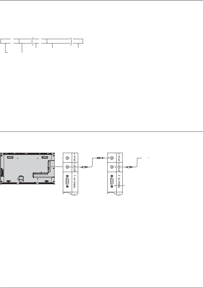
IR IN / IR OUT Terminals connection
Use a 3.5 mm stereo mini plug to connect from the REMOTE OUT of the First LCD Display to the REMOTE IN of the Second LCD Display. The IR signal from the First LCD Display will be sent to the Second LCD Display.
First LCD Display |
Second LCD Display |
* |
At this time, IR of the Second LCD Display will not work.
It is possible to daisy-chained by repeating the above connection.

 Third LCD Display
* |
* Stereo mini plug (M3)
17
Connections
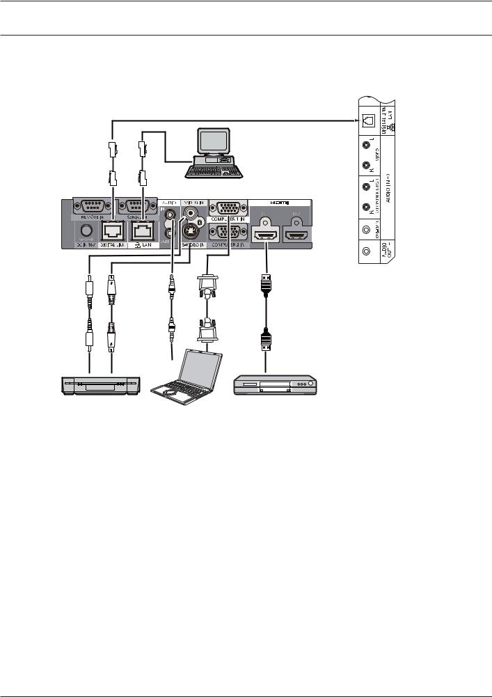
; @J@ := =@$‚
& { > | % =Υ|\]]* &@ : Z @ terminal.
Display Connection Terminals
Control
Computer
When a Panasonic ET-YFB100 is used
Video Cassette Recorder |
DVD Player |
Computer
Notes:
+ ! & : >€& '$‚ K % 47-49)
+ • :€ & & cable transmitter”. (see page 55)
18
Power On / Off
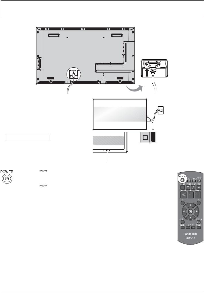
Connecting the AC cord plug to the Display.
Connecting the plug to the Wall Outlet. Notes:
+ When disconnecting the AC cord, be absolutely sure to disconnect the AC cord plug at the socketK
+ Press the Power switch on the Display to turn the set on: Power-On
Power Indicator: Green

 Power switch
 Power Indicator
Remote Control Sensor
1.Press the  button on the remote control to turn the Display off.
Power Indicator: Red (standby)
2.Press the  button on the remote control to turn the Display on.
Power Indicator: Green
3.Turn the power to the Display off by pressing the 
 switch on the unit, when the Display is on or in standby mode.
Note:
+ During operation of the power management function, the power indicator turns orange in the power off state.
19
Power On / Off
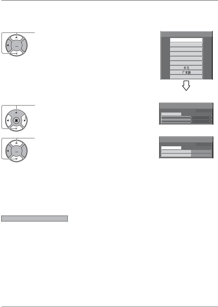
?
• & & Z & > K
Select the items with the remote control. Unit buttons are invalid.
OSD Language
1. Select the language.

 2. Set.
 OSD Language
English (UK)
Deutsch
Français
Italiano
Español
ENGLISH (US)
‘“””•–—
PRESENT TIME Setup
1. Select “DAY” or “PRESENT TIME”.
 2. Setup “DAY” or “PRESENT TIME”.
 PRESENT TIME Setup
PRESENT TIME MON 99 : 99
Set
DAY |
MON |
|
|
PRESENT TIME |
99 : 99 |
1. Select “Set”.

 2. Set.
PRESENT TIME Setup |
|
PRESENT TIME |
MON 99 : 99 |
Set |
TUE |
DAY |
|
PRESENT TIME |
10 : 00 |
Notes:
+ " : & ˜ Z & & K
+ After the setting, the items can be changed in the following menus. OSD Language (see page 39)
PRESENT TIME Setup (see page 32)
Power ON warning message
The following message may be displayed when turning the unit power ON:
No activity power off Precautions
’No activity power off’ is enabled.
If “No activity power off” in Setup menu is set to “Enable”, a warning message is displayed every time the power is turned ON. (see page 36)
This message display can be set with the following menu: |
Options menu |
|
Power On Message (see page 52) |
20
Selecting the input signal
 Press to select the input signal to be played back from the equipment which has been connected to the Display.
Input signals will change as follows:

 HDMI1
HDMI1 HDMI2
HDMI2  VIDEO
VIDEO  Component*
 PC
PC  DVI
DVI  DIGITAL LINK
HDMI1, HDMI2: HDMI1 or HDMI2 input terminal in AV IN (HDMI).
VIDEO: Video input terminal in VIDEO IN.
Component*: Component or RGB input terminal in COMPONENT/RGB IN.
PC: PC input terminal in PC IN.
DVI: DVI input terminal in DVI-D IN.
@J@ := =@$‚• K
*“Component” may be displayed as “RGB” depending on the setting of “Component / RGB-in select”. (see page 42)
Notes:
+ Selecting is also possible by pressing the INPUT button on the unit.
+ Select to match the signals from the source connected to the component/RGB input terminals. (see page 42)
21
 Loading...