


 Loading...
Operating Instructions
Digital High Definition
Plasma Television
Manual de instrucciones Televisor digital con pantalla de plasma de alta definición
Model No. TH-42PX500U
Número de modelo TH-50PX500U
R
For assistance, please call : 1-888-VIEW-PTV (843-9788)
or visit us at www.panasonic.com/contactinfo |
(U.S.A.) |
For assistance, please call : 787-750-4300 |
|
or visit us at www.panasonic.com |
(Puerto Rico) |
For assistance, please call : 1-800-561-5505 |
|
or visit us at www.panasonic.ca |
(Canada) |
Para solicitar ayuda, llame al: 1-888-VIEW-PTV (843-9788)
o visítenos en www.panasonic.com/contactinfo |
(EE.UU.) |
Para solicitar ayuda, llame al: 787-750-4300 |
|
o visítenos en www.panasonic.com |
(Puerto Rico) |
Before connecting, operating or adjusting this product, please read these instructions completely. Please keep this manual for future reference.
Antes de conectar, utilizar o ajustar este producto, lea completamente este manual de instrucciones; y guárdelo para consultarlo en el futuro en caso de ser necesario.
English |
|
Español |
TQB2AA0540 |

CAUTION
RISK OF ELECTRIC SHOCK
DO NOT OPEN
WARNING: To reduce the risk of electric shock, do not remove cover or back. No user-serviceable parts inside. Refer servicing to qualified service personnel.
The lightning flash with arrow-head within a triangle is intended to tell the user that parts inside the product are a risk of electric shock to persons.
The exclamation point within a triangle is intended to tell the user that important operating and servicing instructions are in the papers with the appliance.
WARNING : To reduce the risk of fire or electric shock, do not expose this apparatus to rain or moisture. Do not place liquid containers (flower vase, cups, cosmetics, etc.) above the set (including on shelves above, etc.).
WARNING : 1)To prevent electric shock, do not remove cover. No user serviceable parts inside. Refer servicing to qualified service personnel.
2)Do not remove the grounding pin on the power plug. This apparatus is equipped with a three pin grounding-type power plug. This plug will only fit a grounding-type power outlet. This is a safety feature. If you are unable to insert the plug into the outlet, contact an electrician.
Do not defeat the purpose of the grounding plug.
Note : Do not allow a still picture to be displayed for an extended period, as this can cause a permanent afterimage to remain on the Plasma Television.
Examples of still pictures include logos, video games, computer images, teletext and images displayed in 4:3 mode.
|
|
|
|
|
|
|
|
|
|
|
|
R |
Manufactured under license from Dolby Laboratories. |
|
|
|
|
|
|
|
|
|
|
|
|
|
|
|
|
|
|
|
|
|
|
|
|
|
|
|
“Dolby” and the double-D symbols are trademarks of Dolby Laboratories. |
|
|
|
|
|
|
|
|
|
|
|
|
|
|
|
|
|
|
|
|
|
|
|
|
|
|
|
|
|
|
|
|
|
|
|
|
|
|
|
|
|
|
|
|
|
|
|
|
|
|
|
|
|
|
|
|
|
|
|
|
|
|
|
|
|
|
|
|
|
HDMI, the HDMI logo and High-Definition Multimedia Interface are trademarks or registered trademarks |
|
|
|
|
|
|
|
|
|
|
|
|
|
of HDMI Licensing LLC. |
|
|
|
|
|
|
|
|
|
|
|
|
|
|
License description: To view the license information for software used in this product, press the Menu button and select [Set up]  [About]
  [License]. (See page 34)
This product incorporates copyright protection technology that is protected by U.S. patents and other intellectual property rights. Use of this copyright protection technology must be authorized by Macrovision Corporation, and is intended for home and other limited viewing uses only unless otherwise authorized by Macrovision. Reverse engineering or disassembly is prohibited.
U.S. Patents Nos. 4,631,603; 4,577,216; 4,819,098; 4,907,093; 6,381,747; and 6,516,132.
SD Logo is a trademark.
Manufactured under license from BBE Sound, Inc.
Licensed by BBE Sound, Inc. under USP5510752 and 5736897.
BBE and BBE symbol are registered trademarks of BBE Sound, Inc.
CableCARDTM is a trademark of Cable Television Laboratories, Inc.
In the United States, TV GUIDE and other related marks are registered marks of Gemstar-TV Guide International, Inc. and/or one of its affiliates. In Canada, TV GUIDE is a registered mark of Transcontinental Inc., and is used under licence by Gemstar-TV Guide International, Inc.
The TV Guide On ScreenTM system is manufactured under license from Gemstar-TV Guide International, Inc. and/or one of its affiliates.
The TV Guide On ScreenTM system is protected by one or more of the following issued United States patents 6,498,895, 6,418,556, 6,331,877; 6,239,794; 6,154,203; 5,940,073; 4,908,713; 4,751,578; 4,706,121.
2

Important Safety Instructions
1)Read these instructions.
2)Keep these instructions.
3)Heed all warnings.
4)Follow all instructions.
5)Do not use this apparatus near water.
6)Clean only with dry cloth.
7)Do not block any ventilation openings. Install in accordance with the manufacturer’s instructions.
8)Do not install near any heat sources such as radiators, heat registers, stoves, or other apparatus (including amplifiers) that produce heat.
9)Do not defeat the safety purpose of the polarized or grounding-type plug. A polarized plug has two blades with one wider than the other. A grounding type plug has two blades and a third grounding prong. The wide blade or the third prong are provided for your safety. If the provided plug does not fit into your outlet, consult an electrician for replacement of the obsolete outlet.
10)Protect the power cord from being walked on or pinched particularly at plugs, convenience receptacles, and the point where they exit from the apparatus.
11)Only use attachments / accessories specified by the manufacturer.
12)Use only with the cart, stand, tripod, bracket, or table specified by the
manufacturer, or sold with the apparatus. When a cart is used, use caution when moving the cart / apparatus combination to avoid injury from tip-over.
13)Unplug this apparatus during lightning storms or when unused for long periods of time.
14)Refer all servicing to qualified service personnel. Servicing is required when the apparatus has been damaged in any way, such as power-supply cord or plug is damaged, liquid has been spilled or objects have fallen into the apparatus, the apparatus has been exposed to rain or moisture, does not operate normally, or has been dropped.
15)To prevent electric shock, ensure the grounding pin on the AC cord power plug is securely connected.
FCC STATEMENT
FCC STATEMENT
This equipment has been tested and found to comply with the limits for a Class B digital device, pursuant to Part 15 of the FCC Rules. These limits are designed to provide reasonable protection against harmful interference in a residential installation. This equipment generates, uses and can radiate radio frequency energy and, if not installed and used in accordance with the instructions, may cause harmful interference to radio communications. However, there is no guarantee that interference will not occur in a particular installation. If this equipment does cause harmful interference to radio or television reception, which can be determined by turning the equipment off and on, the user is encouraged to try to correct the interference by one or more of the following measures:
•Reorient or relocate the receiving antenna.
•Increase the separation between the equipment and receiver.
•Connect the equipment into an outlet on a circuit different from that to which the receiver is connected.
•Consult the dealer or an experienced radio/TV technician for help.
This device complies with Part 15 of the FCC Rules. Operation is subject to the following two conditions: (1) This device may not cause harmful interference, and (2) this device must accept any interference received, including interference that may cause undesired operation.
FCC CAUTION:
To assure continued compliance and possible undesirable interference, the provided ferrite cores must be used when connecting this plasma television to video equipment; and maintain at least 40 cm spacing to other peripheral devices. Refer to instructions on pages 6, 12, 14.
Any changes or modifications to this TV not expressly approved by Panasonic Corporation of North America could result harmful interference and would void the user’s authority to operate this device.
FCC Declaration of Conformity
Model No. |
TH-42PX500U, TH-50PX500U |
|
Responsible Party: Panasonic Corporation of North America |
||
|
One Panasonic Way, Secaucus, NJ 07094 |
|
Contact Source: |
Panasonic Consumer Electronics Company |
|
|
1-888-VIEW-PTV (843-9788) |
|
email: |
consumerproducts@panasonic.com |
|
CANADIAN NOTICE:
For Models TH-42PX500U, TH-50PX500U
This Class B digital apparatus complies with Canadian ICES-003.
3

Dear Panasonic Customer
Welcome to the Panasonic family of customers. We hope that you will have many years of enjoyment from your new Plasma TV.
To obtain maximum benefit from your set, please read these Instructions before making any adjustments, and retain them for future reference.
Retain your purchase receipt also, and record the model number and serial number of your set in the space provided on the back cover of these instructions.
Visit our Panasonic Web Site: www.panasonic.com
For assistance, please call : 1-888-VIEW-PTV (843-9788)
or visit us at www.panasonic.com/contactinfo (U.S.A.)
For assistance, please call : 787-750-4300
or visit us at www.panasonic.com (Puerto Rico)
For assistance, please call : 1-800-561-5505
or visit us at www.panasonic.ca (Canada)
Table of Contents
Important Safety Instructions .................................. |
3 |
FCC STATEMENT ...................................................... |
3 |
Safety Precautions .................................................... |
5 |
Cleaning and maintenance....................................... |
6 |
Accessories ............................................................... |
6 |
Installation ................................................................. |
7 |
Receiver Location .................................................. |
7 |
Optional External Equipment ................................. |
7 |
Remote Control Battery Installation ....................... |
7 |
Cable binding instructions ....................................... |
8 |
Connection ................................................................ |
9 |
Antenna Connection .............................................. |
9 |
CableCARDTM Connection ..................................... |
9 |
IR Blaster Connection .......................................... |
10 |
Amplifier Connection (TO AUDIO AMP) ............... |
11 |
Program Out Connection (PROG OUT) ............... |
11 |
Digital TV - Set-Top Box (DTV-STB) or |
|
DVD Connection .................................................. |
12 |
Video Input Connection ........................................ |
12 |
Connecting to the front AV terminals .................... |
12 |
HDMI Connection ................................................. |
13 |
PC Input Terminals Connection............................ |
14 |
Power ON / OFF ....................................................... |
15 |
The Main Unit ....................................................... |
15 |
Location of Controls ............................................... |
16 |
First time setup ....................................................... |
18 |
Watching TV programs ........................................... |
21 |
On-Screen Menu Displays for Navigation............. |
22 |
Menu Navigation ..................................................... |
24 |
Picture .................................................................. |
24 |
Audio .................................................................... |
27 |
Timer .................................................................... |
28 |
Set up ................................................................... |
29 |
Lock ..................................................................... |
35 |
Photo Viewer ........................................................... |
39 |
TV Guide .................................................................. |
43 |
Screen Components ............................................ |
43 |
MAIN SERVICES ................................................. |
44 |
INITIAL GUIDE SETUP for TV Guide ...................... |
49 |
Aspect Controls ...................................................... |
51 |
Split - Screen ........................................................... |
52 |
Operating peripheral equipment............................ |
53 |
Programming the remote control code ................. |
53 |
Infrared Code Index ............................................. |
54 |
Mode Operational Key Chart ............................... |
56 |
VIDEO/COMPONENT/HDMI input signals ............. |
57 |
Specifications .......................................................... |
57 |
Troubleshooting Chart............................................ |
58 |
LIMITED WARRANTY (for U.S.A.) ........................... |
60 |
CUSTOMER SERVICES DIRECTORY (for U.S.A.) .. |
62 |
LIMITED WARRANTY (for Canada) ......................... |
63 |
4

Safety Precautions
 WARNING
SMALL PARTS CAN PRESENT CHOKING HAZARD IF ACCIDENTALLY SWALLOWED.
KEEP SMALL PARTS AWAY FROM YOUNG CHILDREN. DISCARD UNNEEDED SMALL PARTS AND OTHER OBJECTS, INCLUDING PACKAGING MATERIALS AND PLASTIC BAGS/ SHEETS TO PREVENT THEM FROM BEING PLAYED WITH BY YOUNG CHILDREN, CREATING THE POTENTIAL RISK OF SUFFOCATION.
Set up
Do not place the Plasma TV on sloped or unstable surfaces.
• The Plasma TV may fall off or tip over.
Do not place any objects on top of the Plasma TV.
•If water spills onto the Plasma TV or foreign objects get inside it, a short-circuit may occur which could result in fire or electric shock. If any foreign objects get inside the Plasma
TV, please consult an Authorized Service Center.
Do not cover the ventilation holes.
• Doing so may cause the Plasma TV to overheat, which can cause fire or damage to the Plasma TV.
If using the pedestal, leave a space of 3 15/16” (10 cm) or more at the top, left and right, 2 3/8” (6 cm) or more at the bottom, and 2 3/4” (7 cm) or more at the rear. If using some other setting-up method, leave a space of 3 15/16” (10 cm) or more at the top, bottom, left and right, and 3/4” (1.9 cm) or more at the rear.
Avoid installing this product near electronic equipment that is readily affected by electromagnetic waves.
•It may cause interference in image, sound, etc. In particular, keep video equipment away from this product.
AC Power Supply Cord
The Plasma TV is designed to operate on 120 V AC, 50/60 Hz. Securely insert the power cord plug as far as it will go.
•If the plug is not fully inserted, heat may be generated which could cause fire. If the plug is damaged or the wall socket plate is loose, they should not be used.
Do not handle the power cord plug with wet hands.
• Doing so may cause electric shocks.
Do not do anything that might damage the power cable. When disconnecting the power cable, hold the plug, not the cable.
•Do not make any modifications to, place heavy objects on, place near hot objects, heat, bend, twist or forcefully pull the power cable. Doing so may cause damage to the power cable
which can cause fire or electric shock. If damage to the cable is suspected, have it repaired at an Authorized Service Center.
If the Plasma TV will not be used for a long period of time, unplug the power cord from the wall outlet.
If problems occur during use
If a problem occurs (such as no picture or no sound), or if smoke or an abnormal odor is detected from the Plasma TV, unplug the power cord immediately.
•Continued use of the TV under these conditions might cause fire or permanent damage to the unit. Have the TV evaluated at an Authorized Service Center. Servicing of the TV by any unauthorized personnel is strongly discouraged due to its high voltage dangerous nature.
If water or foreign objects get inside the Plasma TV, if the Plasma TV is dropped, or if the cabinet becomes damaged, disconnect the power cord plug immediately.
•A short may occur, which could cause fire. Contact an Authorized Service Center for any repairs that need to be made.
 CAUTION
This Plasma TV is for use only with the following optional accessories. Use with any other type of optional accessories may cause instability which could result in the possibility of injury.
(All of the following accessories are manufactured by Matsushita Electric Industrial Co., Ltd.)
•Pedestal (included) TY-ST42PX500 (TH-42PX500U) TY-ST50PX500 (TH-50PX500U)
•Wall-hanging bracket (Vertical) TY-WK42PV3U
•Wall-hanging bracket (Angled) TY-WK42PR2U
•Floor stand
TY-S42PX500W (TH-42PX500U) TY-S50PX500W (TH-50PX500U)
Always be sure to ask a qualified technician to carry out set-up.
When using the Plasma TV
Do not bring your hands, face or objects close to the ventilation holes of the Plasma TV.
•Top of the Plasma TV is usually very hot due to the high temperature of exhaust air being released through the ventilation holes. Burns or personal injuries can happen if any body parts are brought too close. Placing any object near the top of the
TV could also result in heat damage to the object as well as to the TV if its ventilation holes are blocked.
Be sure to disconnect all cables before moving the Plasma TV.
• Moving the TV with its cables attached might damage the cables which, in turn, can cause fire or electric shock.
Disconnect the power plug from the wall outlet as a safety precaution before carrying out any cleaning.
• Electric shocks can result if this is not done.
Clean the power cable regularly to prevent it from becoming dusty.
•Built-up dust on the power cord plug can increase humidity which might damage the insulation and cause fire. Unplug the cord from the wall outlet and clean it with a dry cloth.
This Plasma TV radiates infrared rays; therefore, it may affect other infrared communication equipment.
Install your infrared sensor in a place away from direct or reflected light from your Plasma TV.
Note:
Do not allow a still picture to be displayed for an extended period, as this can cause a permanent after-image to remain on the Plasma TV.
Examples of still pictures include logos, video games, computer images, teletext and images displayed in 4:3 mode.
5
Cleaning and maintenance
The front of the display panel has been specially treated. Wipe the panel surface gently using only a cleaning cloth or a soft, lint-free cloth.
•If the surface is particularly dirty, soak a soft, lint-free cloth in a weak detergent solution and then wring the cloth to remove excess liquid. Use this cloth to wipe the surface of the display panel, then wipe it evenly with a dry cloth, of the same type, until the surface is dry.
•Do not scratch or hit the surface of the panel with fingernails or other hard objects. Furthermore, avoid contact with volatile substances such as insect sprays, solvents and thinner; otherwise, the quality of the surface may be adversely affected.
If the cabinet becomes dirty, wipe it with a soft, dry cloth.
•If the cabinet is particularly dirty, soak the cloth in a weak detergent solution and then wring the cloth dry. Use this cloth to wipe the cabinet, and then wipe it dry with a dry cloth.
•Do not allow any detergent to come into direct contact with the surface of the Plasma TV.
If water droplets get inside the unit, operating problems may result.
•Avoid contact with volatile substances such as insect sprays, solvents and thinner; otherwise, the quality of the cabinet surface may be adversely affected or the coating may peel off. Furthermore, do not leave it for long periods in contact with articles made from rubber or PVC.
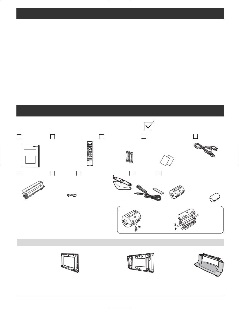
Accessories
Check that you have the Accessories and items shown
Operating |
Remote control |
|
Batteries for the |
Product Registration |
AC cord |
Instruction |
EUR7627Z50 or |
|
remote control |
Card (for U.S.A.) |
|
|
EUR7627Z80 |
|
(AA Battery × 2) |
Customer Care Plan |
|
|
- |
+ |
|
Card (for U.S.A.) |
|
|
1 |
2 |
3 |
|
|
|
4 |
5 |
6 |
|
|
|
7 |
8 |
9 |
|
|
|
|
0 |
|
|
|
Cable clamper |
F-Type |
Pedestal |
IR Blaster |
× 2 |
antenna |
TY-ST42PX500 |
( × 1) |
|
adapter |
(TH-42PX500U) |
TNQX016 |
|
(for 5C-2V) |
TY-ST50PX500 |
|
|
( × 1) |
(TH-50PX500U) |
|
Ferrite core Large size × 1 ZCAT3035-1330
Small size Gray color × 1
ZCAT2235-1030 White color × 4 RFC-8 
Attaching the ferrite core |
1 |
|
2 |
|
Be sure to choose the appropriate size of ferrite core |
Pull back the |
|||
|
|
|||
(large or small) and the correct setting of the cable |
|
tabs (in two |
Put the cable |
|
(winding), as indicated by each connection diagram on |
|
places) to |
||
the following pages (12, 14). |
|
open. |
and close. |
Optional Accessories
•Wall-hanging bracket (vertical) TY-WK42PV3U
•Wall-hanging bracket (Angled) TY-WK42PR2U
•Floor stand TY-S42PX500W (TH-42PX500U) TY-S50PX500W (TH-50PX500U)
6

Installation
Receiver Location
This unit is intended to be used with the stand or bracket. Consult your dealer for available options. Position for comfortable viewing. Avoid placing where sunlight or other bright light (including reflections) will fall on the screen. Use of some types of fluorescent lighting can reduce remote control transmitter range.
Adequate ventilation is essential to prevent internal component failure. Keep away from areas of excessive heat or moisture.
Optional External Equipment
The Video/Audio connection between components can be made with shielded video and audio cables. For best performance, video cables should utilize 75 ohm coaxial shielded wire. Cables are available from your dealer or electronic supply store.
Before you purchase any cables, be sure you know what type of output and input connectors your various components require. Also determine the length of cable you will need.
Remote Control Battery Installation
1. Open the cover. |
2. Install the batteries and replace the cover. |
|
Note the correct polarity (+ and -). |
|
Two AA size |
Helpful Hints:
For frequent remote control users, replace old batteries with alkaline batteries for longer life.
Helpful Hints:
Whenever you remove the batteries, you may need to reset the remote control infrared codes. We recommend that you record the code on page 54, prior to setting up the remote control.
 Precaution on battery use
Incorrect installation can cause battery leakage and corrosion that will damage the remote control transmitter.
Observe the following precautions:
1.Batteries should always be replaced as a pair. Always use new batteries when replacing the old set.
2.Do not combine a used battery with a new one.
3.Do not mix battery types (example: “Zinc Carbon” with “Alkaline”).
4.Do not attempt to charge, short-circuit, disassemble, heat or burn used batteries.
5.Battery replacement is necessary when remote control acts sporadically or stops operating the TV set.
7

Cable binding instructions
Cable cover |
AC cord |
Removal |
|
|
|
1 |
Push down hooks and pull the |
Clamper |
|
|
cover slightly towards yourself to |
|
|
|
Open |
Close |
|
|
disengage the claws (at 2 points). |
||
2 |
Slowly pull out in the upward |
|
Clamp |
|
direction. |
|
How to fix: |
|
Fitting |
|
Fix by pushing in |
|
|
|
|
|
|
|
until a clicking |
|
|
|
sound is heard. |
|
|
|
How to release: |
1 |
Insert the claws (at 2 points) at the |
|
Pull down while |
|
drawing the knob. |
||
|
bottom end. |
|
|
2 |
Push until it clicks. |
|
|
Note: To avoid interference appearing on the screen, do not bundle the RF cable and mains lead together.
Cable binding condition
Attach the bands.
Insert the spigot on the two bands into the pedestal.
Fastening band
 Band
Band
Fastening
To tighten. 
Loosening
Pull off.
Connect cables.
Example of “connection cable routing”
AC cord 
Clamp
Binding strap
Band
Keep the knob pressed.
8

Connection
Note:
Cables and connectors are not supplied with this set.
Antenna Connection |
|
|
|
|
The RF input mode must be set to Antenna |
|
|
|
|
(see pages 19, 30). |
|
Home antenna |
|
|
|
|
|
||
Back of the TV |
|
VHF |
UHF |
|
|
Antenna |
|
|
Incoming |
ANTENNA |
Terminal |
|
or |
|
C a b l e I n |
|
|
|
Cable signal |
|
|
|
|
|
|
F-Type Antenna |
|
Mixer |
|
|
|
|
|
|
|
Connector |
|
|
|
75 Ohm Coaxial Cable (5C-2V or higher specification)
CableCARDTM Connection
CableCARDTM allows you to tune digital and high definition cable channels through the cable antenna. Consult your cable company on the availability of CableCARDTM.
Procedure
1.Connect the cable antenna to ANT connector.
2.Turn the TV on (see page 15).
3.Set the input mode to TV (see page 16).
4.Insert the CableCARDTM (with upper side facing you) into CableCARDTM slot on the back of the TV. Follow the messages displayed on the screen.
Back of the TV
G- |
AUDIOGITAL |
|
|
LINK |
I |
|
OUT |
|
Upper side of the card
MODULE POD

C |
|
a b |
|
le |
|
|
C A |
|
R |
INSERTTHISEND |
|
D
TM
AN |
TENNAbl |
||
C a |
|||
e |
In |
||
|
|||
|
|
||
Notes:
•If you experience keyboard or remote control function hang-up when using CableCARDTM , unplug the TV and plug it back on and try the controls again. If this condition persists, please call Panasonic Customer Call Center for further instructions.
•Do not insert a PCMCIA card into CableCARDTM slot.
9
Connection
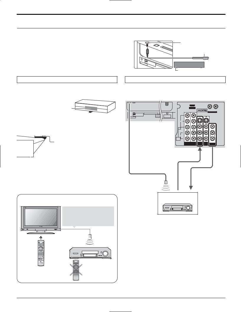
IR Blaster Connection
With the IR Blaster connection setting timer recording can be done easily by using the TV GUIDE function in this set.
Connect the IR Blaster if you wish to send remote control signals from the plasma TV to control the recording of a connected video recorder.
Position the IR Blaster remote control emitter facing the signal sensor of the video recorder and you will be able to easily record programs from digital broadcasts using a video recorder connected to the plasma TV.
G- |
AUDIOGITAL |
|
|
LINK |
I |
|
OUT |
|
G-LINK jack
IR Blaster (Supplied)
 Infrared emitter
Video recorder (VCR)
Setting the IR Blaster
Place the IR Blaster in front of the signal sensor of the video recorder. (VCR)
Read the video recorder o p e r a t i n g i n s t r u c t i o n s regarding positioning of the signal sensor.
If necessary, use the double sided adhesive tape (included) to secure the IR Blaster to a flat surface.
|
|
|
|
|
|
|
e.g. Television stand surface |
|
|
|
|
|
|
||
|
|
|
|
|
|
|
|
|
|
|
|
|
|
|
If you peel off the adhesive tape, the |
|
|
|
|
|
|
|
|
|
|
|
|
|
|
||
|
|
|
|
|
|
|
surface may become damaged. |
|
|
|
|
|
|
|
Once you have confirmed the video |
|
|
|
|
|
|
|
recorder is operating correctly, |
|
|
|
|
|
|
|
|
|
|
|
|
|
|
||
|
|
|
|
|
|
|
secure it by attaching the adhesive |
Video recorder |
|
||||||
|
tape. |
||||||
|
|
|
|
|
|
|
|
Introduction to recording scheduling using the IR
Blaster
You may do recording scheduling from the TV Guide of this
TV after installing the IR Blaster. (See page 43)
The TV acts as a proxy for some remote control operations of the VCR.
Converts scheduling data displayed on the TV to a remote control signal and sends it
TV
|
|
R |
|
|
ECAL |
|
- |
+ |
1 |
2 |
3 |
4 |
5 |
6 |
7 |
8 |
9 |
|
0 |
|
Setting the recording time, channel and recording mode, etc.
VCR
No need to set recording time or channel on the video recorder
Settings other than basic ones (such as recording time and channel) must be set on the VCR.
INPUT / OUTPUT Connection
Connection for recording to a VCR by using TV GUIDE
G-LINK |
Back of the TV |
|||
|
|
|
AV IN |
R L |
|
|
|
|
|
|
|
|
Y |
AUDIO IN |
D I G I TA L |
|
|
Y |
|
|
|
|
|
|
AUDIO OUT |
ANTENNA |
|
|
|
G - L I N K |
C a b l e I n |
|
PB |
PB |
|
|
|
||
|
VIDEO |
|
|
S VIDEO |
|
|
|
|
|
|
|
|
PR |
PR |
|
|
|
|
VIDEO |
|
PC |
|
|
|
|
|
L |
|
|
|
AUDIO |
|
|
|
|
AUDIO |
R |
|
|
|
IN |
|
|
|
|
|
|
|
|
|
|
1 |
2 |
TO AUDIO AMP |
|
|
COMPONENT VIDEO INPUT 1 INPUT 2 PROGOUT |
||
|
|
|
INPUT |
|
To INPUT 1
IR Blaster
from PROG.OUT
VCR
Notes:
•The input signals connected to INPUT 1 cannot be output from PROG. OUT terminals. (both Video and audio) However, output can be obtained from optical Digital Audio terminals.
(Input signals other than from INPUT 1 can be output from PROG. OUT.)
•When you make schedule recording using TV Guide with IR blaster, you have to select in your VCR Line-1 (L-1) and set your VCR in OFF condition.
(Refer to the Operating Instruction manual of VCR)
10
Connection
Amplifier Connection (TO AUDIO AMP)
For a full Home Theater sound experience, an external Dolby Digital decoder and a multichannel amplifier must be connected to the DIGITAL AUDIO OUT terminal on the TV.
Dolby Digital 5.1 channel surround sound delivers digital-quality sound. Dolby Digital provides five discrete fullbandwidth channels for front left, front right, center, surround left and surround right, plus a LFE (Low Frequency Effect) subwoofer channel.
OPTICAL IN |
Optical digital audio cable |
Amplifier |
or
AUDIO INPUT
L
D I G I T A L
A U D I O O U T
|
|
|
|
|
|
|
|
|
|
|
|
|
|
|
|
|
|
|
|
|
|
|
|
|
|
|
|
|
|
|
|
|
|
|
|
|
|
|
|
|
|
|
|
|
|
|
|
|
|
|
|
|
|
|
|
|
|
|
|
|
|
D I G I TA L |
|
|
C a b l e C A R D T M |
|
|
|
|||
|
AUDIO OUT |
|
|
|
|
ANTENNA |
|
||||
G - L I N K |
|
|
|
|
|
C a b l e I n |
|
||||
L
R |
R |
|
Audio cable |
OUTPUT
Procedure
AUDIO OUT
1.Select Speakers “Off” in Audio menu (see page 27).
2.Adjust the amplifier volume to the desired level.
Notes:
G- |
AUDIOIGITAL |
|
|
LINK |
OUT |
|
|
|
 Back of the TV
|
|
AV IN |
R |
L |
|
|
|
||
|
|
|
AUDIO IN |
|
|
|
Y |
Y |
|
|
|
PB |
PB |
|
VIDEO |
|
|
S VIDEO |
|
|
|
|
|
|
|
|
PR |
PR |
|
|
|
|
|
VIDEO |
PC |
|
|
|
|
|
|
|
L |
|
|
L |
|
|
|
AUDIO |
|
|
|
|
AUDIO |
R |
|
|
|
IN |
|
|
|
|
|
|
R |
|
|
|
|
|
|
|
|
1 |
2 |
TO AUDIO AMP |
|
|
COMPONENT VIDEO INPUT 1 INPUT 2 PROGOUT |
|||
|
|
INPUT |
|
|
•Depending on your DVD player and DVD-Audio software the copyright protection function may operate and disable optical output.
•External speakers cannot be connected directly to OUTPUT terminals.
•When ATSC channel is selected, the output from the DIGITAL AUDIO OUT jack will be Dolby Digital. When NTSC channel is selected, the output will be PCM.
Program Out Connection (PROG OUT)
See optional equipment manual for further instructions for recording and monitoring.
|
|
Back of the TV |
|||
|
|
|
|
AV IN |
R L |
VCR |
VIDEO |
|
|
|
|
|
|
Y |
Y |
||
|
|
|
|
|
AUDIO IN |
DVD recorder |
INPUT |
|
|
|
|
|
|
|
PB |
PB |
|
|
|
|
|
||
|
|
VIDEO |
|
|
S VIDEO |
|
L |
|
|
|
|
|
|
|
PR |
PR |
|
|
AUDIO |
|
|
||
|
|
|
|
VIDEO |
|
|
INPUT |
PC |
|
|
L |
|
R |
|
|
|
|
|
|
|
|
|
|
|
AV cable |
OUTPUT AUDIO |
L |
|
|
|
|
|
|
||
|
|
AUDIO |
|
|
|
|
|
IN |
R |
|
|
|
|
|
|
R |
|
|
|
|
|
|
|
|
|
|
1 |
2 |
TO AUDIO AMP |
|
|
|
COMPONENT VIDEO INPUT 1 INPUT 2 PROGOUT |
||
|
|
|
|
INPUT |
|
Notes:
•The input signals connected to INPUT1 cannot be output from PROG. OUT terminals. (both picture and audio) However, output can be obtained from optical Digital Audio terminals.
(Input signals other than from INPUT1 can be output from PROG. OUT.)
•Connect the output of the Video recorder to INPUT1, when recording by using TV GUIDE.
•When a device (STB, DVD, etc.) is connected to the HDMI or COMPONENT terminals (see pages 12, 13), only audio signals will be output. No video signals will be output.
•When a schedule recording is activated on the TV Guide, the show will be recorded on a connected VCR. Please note that the screen will automatically be switched to the channel of the recorded show.
•When receiving digital channel signals, all digital formats are down-converted to composite NTSC video to be output through Program Out terminals.
•Some programs contain a Macrovision signal to prevent VCR recording.
11

Connection
Digital TV - Set-Top Box (DTV-STB) or DVD Connection
This TV is capable of displaying 1080i, 720p, 480p and 480i DTV signals when connected to a DTV Tuner Set-Top Box (STB). This TV also utilizes a progressive scan doubler, which de-interlaces the NTSC signal and progressively scans the image.
•To view DTV programs, connect the STB to the component video input terminals (Y, PB, PR) of the TV. Component color inputs provide luminance and separate color signal.
•Set the output of the STB to either 1080i, 720p, 480p or 480i.
•A DTV signal must be available in your area.
• Use a Panasonic DTV-STB (Digital TV-Set-Top Box) or DVD Player. |
Back of the TV |
|
COMPONENT |
|
VIDEO OUT |
Set Top Box |
Y |
|
|
|
PB |
DVD player |
PR |
|
|
|
AUDIO OUTPUT |
|
L |
|
R |
Note: |
|
Component Video cable
Audio cable
Y
PB
VIDEO
PR
L
AUDIO
R
|
|
AV IN |
R |
L |
|
|
|
||
|
|
|
AUDIO IN |
|
|
|
Y |
Y |
|
|
|
PB |
PB |
|
VIDEO |
|
|
S VIDEO |
|
|
|
|
|
|
|
|
PR |
PR |
|
|
|
|
|
VIDEO |
PC |
|
|
|
|
|
|
|
L |
|
|
L |
|
|
|
AUDIO |
|
|
|
|
AUDIO |
R |
|
|
|
IN |
|
|
|
|
|
|
R |
|
|
|
|
|
|
|
|
1 |
2 |
TO AUDIO AMP |
|
|
COMPONENT VIDEO INPUT 1 INPUT 2 PROGOUT |
|||
|
|
INPUT |
|
|
COMPONENT VIDEO
INPUT 1/2
All signals will be re-formatted for viewing on your plasma display.
Video Input Connection
VCR |
|
|
CAMCORDER |
S-VIDEO |
|
|
OUT |
|
|
VIDEO |
|
|
OUT |
|
VIDEO GAME |
L |
|
CONSOLE |
||
AUDIO |
||
|
||
|
OUT |
|
|
R |
S-Video cable
Video cable
Audio cable
Back of the TV
|
|
AV IN |
R |
L |
|
|
|
||
|
|
|
AUDIO IN |
|
|
|
Y |
Y |
|
|
|
PB |
PB |
|
VIDEO |
|
|
S VIDEO |
|
|
|
|
|
|
|
|
PR |
PR |
|
|
|
|
|
VIDEO |
PC |
|
|
|
|
|
|
|
L |
|
|
L |
|
|
|
AUDIO |
|
|
|
|
AUDIO |
R |
|
|
|
IN |
|
|
|
|
|
|
R |
|
|
|
|
|
|
|
|
1 |
2 |
TO AUDIO AMP |
|
|
COMPONENT VIDEO INPUT 1 INPUT 2 PROGOUT |
|||
|
|
INPUT |
|
|
INPUT 1 / 2
Note:
The S Video input will override the composite video signal when S Video cable is connected. Connect either S Video cable or Video cable.
Connecting to the front AV terminals
Push to open the front panel and connect equipment to front Audio/Video input terminals.
Ferrite core (Large size) (supplied)
A second VCR, video disc player, video game equipment and DSS equipment can also be connected to the video input terminals. See the optional equipment manual for details.
Note:
The S-VIDEO connection provides higher quality picture. It overrides other VIDEO connections. Use INPUT 3, AUDIO L and R with S-VIDEO connection.
Ferrite core (Small size white color) (supplied)
Audio cable |
CAMCORDER |
Video cable
S-Video cable
12

Connection
HDMI Connection
HDMI 1 (High Definition Multi media Interface) is the first all digital consumer electronics A/V interface that supports uncompressed standard. The HDMI terminal supports both video and audio information.
To the HDMI 1 input terminal, you can connect an EIA/CEA-861/861B 2 compliant consumer electronic device, such as a Set-Top Box or DVD player with HDMI or DVI output terminal.
Input a High-bandwidth Digital Content Protection (HDCP) high-definition picture source to this HDMI terminal, so you can display high-definition pictures on this TV in digital form.
HDMI cable |
HDMI cable |
|

 Audio cable
|
|
AV IN |
|
|
|
|
|
R |
L |
|
|
|
AUDIO IN |
|
|
|
Y |
Y |
|
|
|
PB |
PB |
|
VIDEO |
|
|
S VIDEO |
|
|
|
|
|
|
|
|
PR |
PR |
|
|
|
|
|
VIDEO |
PC |
|
|
|
|
|
|
|
L |
|
|
L |
|
|
|
AUDIO |
|
|
|
|
AUDIO |
R |
|
|
|
IN |
|
|
|
|
|
|
R |
|
|
|
|
|
|
|
|
1 |
2 |
TO AUDIO AMP |
|
|
COMPONENT VIDEO INPUT 1 INPUT 2 PROGOUT |
|||
|
|
INPUT |
|
|
•If connecting with an HDMI cable, it is not necessary to connect an audio cable.
•If connecting to equipment
that has only a DVI output t e r m i n a l , H D M I - D V I conversion cable and an audio cable are necessary. 3
•Select the audio setting in HDMI In (see page 27).
R L HDMI
AUDIO |
OUT |
OUT |
|
HDMI signal out
Set Top Box |
DVD player |

 Compatible VIDEO Signal
1080i
720p
480p
480i
No. of dots (H × V) |
Vertical scanning frequency (Hz) |
1,920 × 1,080i |
59.94/60 |
1280 × 720p |
59.94/60 |
720 × 480p, 640 × 480p |
59.94/60, 59.94/60 |
720(1,440) × 480i |
59.94/60 |
|
|
Notes:
•This input terminal is not intended for use with computers.
•All signals will be re-formatted for viewing on your plasma display.

 Compatible sampling frequency of AUDIO signal through HDMI (L.PCM) : 48 kHz / 44.1 kHz / 32 kHz Notes:
•This HDMI connector is Type A.
•If you connect equipment without a digital output terminal, connect to the COMPONENT VIDEO, S VIDEO or VIDEO input terminal on the TV so you can enjoy an analog signal.
•If you cannot display the picture because your Digital Set-Top Box does not have a DIGITAL OUT terminal Output setting, use the component Video Input (or the S Video Input or Video Input). In this case the picture will be displayed as an analog signal.
1.HDMI, the HDMI logo and High-Definition Multimedia Interface are trademarks or registered trademarks of HDMI Licensing LLC.
2.EIA/CEA-861/861B profiles compliance covers profiles for transmission of uncompressed digital video including high bandwidth digital content protection.
3.HDMI-DVI conversion cable (TY-SCH03DH): available from Panasonic Website. Consult your consumer electronics dealer for availability details.
13
Connection
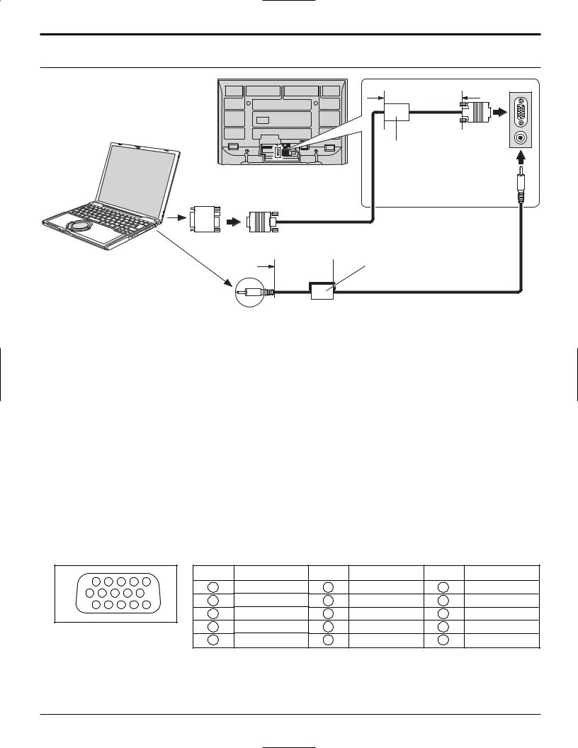
PC Input Terminals Connection
|
Less than |
|
10cm (4”) |
COMPUTER |
D-sub 15p |
|
|
|
Ferrite core |
|
(Small size gray color) |
Conversion adapter (if necessary) |
Stereo plug |
RGB
PC cable
Less than
10cm (4”)  Ferrite core
(Small size white color)
Audio
Connect a cable which matches the audio output terminal on the computer.
Notes:
(1)Computer signals which can be input are those with a horizontal scanning frequency of 15 to 110 kHz and vertical scanning frequency of 48 to 120 Hz. (However, the image will not be displayed properly if the signals exceed 1,200 lines.)
(2)The maximum resolution:
Model |
|
Aspect |
|
4:3 |
|
16:9 |
|
|
|
||
TH-42PX500U |
768 × 768 |
|
1,024 × 768 |
TH-50PX500U |
1,024 × 768 |
|
1,366 × 768 |
If the display resolution exceeds these maximums, it may not be possible to show fine detail with sufficient clarity.
(3)Some PC models cannot be connected to the set.
(4)There is no need to use an adapter for computers with IBM PC/AT compatible D-sub 15P terminal.
(5)The computer shown in the illustration is for example purposes only.
(6)Additional equipment and cables shown are not supplied with this set.
Signal Names for D-sub 15P Connector |
|
|
|
|
|
|||||||
11 |
12 |
13 |
|
14 |
15 |
Pin No. |
Signal Name |
Pin No. |
Signal Name |
Pin No. |
Signal Name |
|
|
1 |
R |
6 |
GND (Ground) |
11 |
NC (not connected) |
||||||
6 |
7 |
8 |
9 |
10 |
||||||||
2 |
G |
7 |
GND (Ground) |
12 |
NC |
|||||||
1 |
2 |
3 |
|
4 |
5 |
|||||||
|
3 |
B |
8 |
GND (Ground) |
13 |
HD/SYNC |
||||||
|
|
|
|
|
|
|||||||
Pin Layout for PC Input |
4 |
NC (not connected) |
9 |
NC (not connected) |
14 |
VD |
||||||
5 |
GND (Ground) |
10 |
GND (Ground) |
15 |
NC |
|||||||
Terminal |
|
|
|
|
|
|||||||
14

Power ON / OFF
POWER button |
|
Press to turn the |
|
TV’s main power |
|
on/off. |
|
|
Remote control |
|
sensor |
POWER |
Within about 23 |
|
feet (7 meters) in |
|
front of the TV set. |
Power indicator |
C.A.T.S. |
Power on : Red |
Plasma C.A.T.S. (Contrast |
Power off : No Light |
Automatic Tracking System). |
|
See page 24. |
POWER
SAP
LIGHT
TV VCR DVD
DTV RCVR DBS/CBL AUX
TV/VIDEO |
SLEEP |
EXIT |
1 Connect the AC cord plug to the Plasma TV.
•Fix the power cord plug securely with the clamper (see page 8).
2 Connect the plug to the wall outlet.
3 Press POWER button on front of this unit. First time setup is displayed on screen.
First time setup
Language
Clock
Auto program
(Refer to page 18-20 for operation)
4 |
POWER |
Press to turn the TV on or off. |
Notes:
•The TV will still consume some power as long as the power cord is inserted into the wall outlet.
•The First time setup screen is displayed only the first time you turn the power on after purchase.
If you wish to change the settings of these items later, select them via the Setup menu.
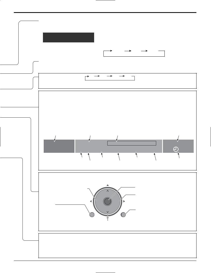
The Main Unit
Open the front cover
Raise the lower part of the door labeled “PULL”.
Video Input 3 connector
PC CARD slot
Change the TV Channel.
(Move cursor to up or down during menu mode.) Adjust the volume level.
(Move cursor to right or left during menu mode.)
Change the input mode.
Choose menu and submenu entry.
Display the Main menu.
Display the TV GUIDE.
15

Location of Controls
POWER
Turn the TV ON or OFF.
Mode Selection buttons (see page 53-55)
TV |
: TV |
|
RCVR |
|
: Receiver/Amplifier |
|
|
|
|
|
|
|
|
|
|
|
|
VCR : VCR |
|
DBS/CBL : Digital Broadcast System/Cable TV |
|
|
|
|
|
|
|
|
|
|
|
||||
DVD : DVD |
|
AUX |
|
: Aux |
|
|
|
|
|
|
|
|
|
|
|
||
DTV : Digital TV |
|
|
|
POWER |
|
|
|
|
|
|
|
|
|||||
|
|
|
|
|
|
|
|
|
|
|
|
|
|
|
|||
|
|
|
|
|
|
|
|
|
|
|
|
|
|
|
|
|
SAP |
TV/VIDEO |
|
|
|
|
|
|
|
|
|
|
|
|
|
|
LIGHT |
||
Change the input mode. |
|
|
|
|
|
|
|
|
|
|
|
|
|||||
|
|
TV |
VCR |
DVD |
|
||||||||||||
• Press to display the Input selection menu. |
|
||||||||||||||||
|
|
|
|
|
|
|
|
|
|
|
|||||||
Input select |
|
• Press corresponding number key on the remote |
DTV |
RCVR |
DBS/CBL |
AUX |
|||||||||||
[1] TV |
|
|
|||||||||||||||
|
|
control to select the input of your choice. |
TV/VIDEO |
|
|
|
|
SLEEP |
EXIT |
||||||||
[2] Component 1 |
|
|
|
|
|||||||||||||
Note: |
|
|
|
|
|
|
|
|
|
|
|
|
|
||||
[3] Component 2 |
|
|
|
|
|
|
|
|
|
|
|
|
|
||||
Video input can also be selected by pressing TV/VIDEO , |
|
|
|
|
|
|
|
|
|
|
|
||||||
[4] HDMI |
|
|
|
|
|
|
|
CT FA |
|
|
|
||||||
|
|
|
|
|
|
|
|
|
|
|
|
|
|
|
|
||
|
|
|
|
|
|
|
|
|
|
|
|
E |
VO |
R |
|
|
|
|
|
|
|
|
|
|
|
|
|
|
P |
|
|
|
|
||
[5] Video 1 |
|
then the CH |
buttons, then pressing “OK” key. |
|
|
|
S |
|
|
|
I |
|
|||||
|
|
|
|
A |
|
|
|
|
|
TE |
R |
||||||
[6] Video 2 |
|
|
|
|
|
|
T |
|
|
|
|
|
|
|
|||
|
|
|
|
|
|
|
|
|
|
|
|
|
|
|
|
A |
|
[7] Video 3 |
|
|
|
|
|
U |
|
|
|
|
|
|
|
|
C |
||
|
|
|
|
M |
|
|
|
|
CH |
|
|
|
L |
||||
|
|
|
|
|
|
|
|
|
|
|
|
|
|
|
|
|
L |
[8] PC |
|
|
|
|
|
|
|
|
|
|
|
|
|
|
|
|
|
|
|
|
|
|
|
|
|
|
-VOL OK VOL+ |
||||||||
SD |
|
|
|
|
|
|
MENU |
|
|
|
CH |
|
|
|
RETURN |
||
Access SD Memory Card. (see page 39). |
|
|
|
|
|
|
|
|
|
|
|
||||||
|
|
|
|
|
|
|
TVGUIDE |
|
INFO |
|
|
PAGE |
|||||
TVGUIDE |
INFO |
|
PAGE |
|
|
|
|
|
|
|
|
|
|
|
|
|
|
|
|
|
|
|
|
|
|
1 |
|
|
|
2 |
|
|
|
3 |
|
|
|
|
|
|
Page scroll on TV Guide |
|
4 |
|
|
|
5 |
|
|
|
6 |
||
|
|
|
|
|
Press to display a help screen on TV Guide |
|
|
|
|
|
|
|
|||||
|
|
|
|
|
|
|
|
|
|
|
|
|
|
|
|
||
|
|
|
|
|
Press to enter the TV Guide |
|
7 |
|
|
|
8 |
|
|
|
9 |
||
|
|
|
|
|
(see page 43) |
R-TUNE |
|
|
|
0 |
|
|
|
PROG |
|||
|
|
|
|
|
|
|
|
|
|
|
|
|
|
|
|
|
|
R-TUNE |
|
|
|
|
|
|
REW |
|
|
|
PLAY |
|
|
FF |
|||
Switch to previously viewed channel and input modes. |
|
|
|
|
|
||||||||||||
|
|
|
|
|
|
|
|
|
|
|
|||||||
|
|
|
|
|
|
|
PAUSE |
|
|
|
STOP |
|
|
REC |
|||
REW |
|
PLAY |
FF |
|
|
|
|
|
|
|
|
|
|
|
|
|
|
|
|
|
|
|
|
|
TV/VCR |
|
SPLIT |
SWAP |
OPEN/CLOSE |
||||||
PAUSE |
|
STOP |
REC |
|
|
|
DVD/VCR CH |
|
|||||||||
|
Operation of other Device |
|
|
|
|
|
|
|
|
|
|
|
|||||
|
|
|
|
|
|
|
|
|
|
|
|
|
|
|
|
||
|
|
|
|
|
(see page 56) |
|
|
|
|
|
|
|
|
|
|
|
|
|
|
SPLIT |
SWAP |
|
|
|
|
|
|
|
|
|
|
|
|
|
|
TV/VCR |
|
DVD/VCR CH |
OPEN/CLOSE |
|
|
|
|
|
|
|
|
|
|
|
|
|
|
|
|
|
|
|
SWAP |
|
|
|
|
|
|
|
|
|
|
|
|
|
|
|
|
|
Swap pictures in SPLIT operation |
|
|
|
|
|
|
TV |
|
|
|
||
|
|
|
|
|
(see page 52). |
|
|
|
|
|
|
|
|
|
|||
|
|
|
|
|
|
|
|
|
|
|
|
|
|
|
|
||
|
|
|
|
|
SPLIT |
|
|
|
|
|
|
|
|
|
|
|
|
|
|
|
|
|
Split Screen (see page 52) |
|
|
|
|
|
|
|
|
|
|
|
|
16
Location of Controls
SAP
•Digital channel
Select the audio track (if available).
Audio Track 1 of 1
(English)
• Analog channel |
Stereo |
SAP |
Mono |
|
Cycle through different audio modes. |
||||
|
|
|
LIGHT
Illuminate the remote control buttons. The selected button blinks when lit.
SLEEP timer (minutes) |
0 |
30 |
60 |
90 |
EXIT menus Normal viewing, from each menu.
MUTE
Mute the sound. Press again to cancel mute.
ASPECT
Change the screen aspect (see page 51).
RECALL
Display or remove the channel banner.
Channel, Program |
|
and Station identifier |
Program end time |
|
FAVORITE
Channel numbers registered in Favorite are displayed on the favorite tune screen. Select the desired broadcast station with the cursor, or using number keys.
Program title |
Clock |
15-2 |
- 10:30 |
|
Andrew’s cooking show |
10:00 am |
||||
ABC - HD |
CC |
SAP |
TV-G |
|
1080I |
Standard |
4 : 3 |
30 |
Closed Caption |
Rating |
|
Picture mode setting |
Time remaining |
||||
|
|
SAP indication |
|
Signal resolution |
Aspect |
|||
|
|
|
in Sleep Timer |
|||||
|
|
|
|
|
|
|
|
|
 CH: Change to the next channel up.
 : Move cursor upward during menu mode.
- VOL : Reduces volume.  - : Move cursor to the left CH
during menu mode.
MENU |
-VOL |
OK |
VOL+ |
|
|
|
|
Display Main Menu |
MENU |
CH |
RETURN |
Choose menu and submenu entry.
VOL +: Increase volume.
+: Move cursor to the right during menu mode.
RETURN
Press to return to previous Menu.
 CH: Change to the next channel down.
 : Move cursor downward during menu mode.
Direct program number selection buttons
PROG -: When tuning digital channel, press the button to enter the minor number in a compound channel number.
•To enter the channel number
e.g. CH 15-1: [1]  [5]
[5] [-]
[-] [1]
[1]  [OK]
[OK]
17

First time setup
For your convenience, First time setup menu will be displayed on screen when the set is turned on for the first time. If needed, follow the menus and procedures displayed on-screen for setting up the features.
You can also adjust the settings in Setup menu (see pages 29-31).
|
|
|
|
|
|
|
|
|
|
|
|
|
Language |
|
||
POWER |
|
|
|
|
|
|
|
|
|
|
|
|
||||
|
|
|
|
|
|
|
|
|
|
|
|
SAP |
Allows you to select the language used for On |
|||
|
|
|
|
|
|
|
|
|
|
|
|
|
Screen Displays. |
|
||
|
|
|
|
|
|
|
|
|
|
|
|
LIGHT |
|
|
Press to select “Language”. |
|
TV |
VCR |
DVD |
|
|
|
|||||||||||
DTV |
RCVR |
DBS/CBL |
AUX |
CH |
|
Press to display “Language” |
||||||||||
-VOL OK |
VOL+ |
|||||||||||||||
TV/VIDEO |
|
|
|
|
SLEEP |
EXIT |
screen. |
|||||||||
|
|
|
|
|
|
|||||||||||
|
|
|
|
|
|
|
|
|
|
|
|
|
CH |
|
|
|
|
|
|
|
|
|
|
CT |
FA |
|
|
|
|
|
|
|
|
|
|
|
|
|
|
E |
VO |
RI |
|
|
|
|
|
|||
|
|
|
|
|
P |
|
|
|
|
|
|
|
|
|||
|
|
|
|
S |
|
|
|
|
T |
|
|
|
|
|||
|
|
|
|
A |
|
|
|
|
|
|
E |
R |
|
|
|
|
|
|
|
E |
|
|
|
|
|
|
|
|
|
|
|
||
|
|
|
|
|
|
|
|
|
|
|
C |
|
|
|
||
|
U |
T |
|
|
|
|
|
|
|
|
|
E |
|
|
|
|
M |
|
|
|
|
|
|
|
|
|
A |
CH |
|
|
|||
|
|
|
|
|
CH |
|
|
|
|
L |
|
Press to select “English”, |
||||
|
|
|
|
|
|
|
|
|
|
L |
|
|
||||
|
|
|
|
|
|
|
|
|
|
|
|
|
|
|
||
|
|
|
|
|
|
|
|
|
|
|
|
|
-VOL OK |
VOL+ |
“Español” or “Français”. |
|
|
|
|
-VOL OK |
|
VOL+ |
|
|
|||||||||
|
|
|
|
CH |
|
|
||||||||||
|
|
|
|
|
|
|
|
|
|
|
|
|
|
|
||
MENU |
|
|
|
CH |
|
|
|
|
RETURN |
|
|
|
||||
|
|
|
|
|
|
|
|
|
|
|
|
|
|
|
Press to move the cursor to . |
|
CH
 Press to go to previous screen.
-VOL OK VOL+
CH
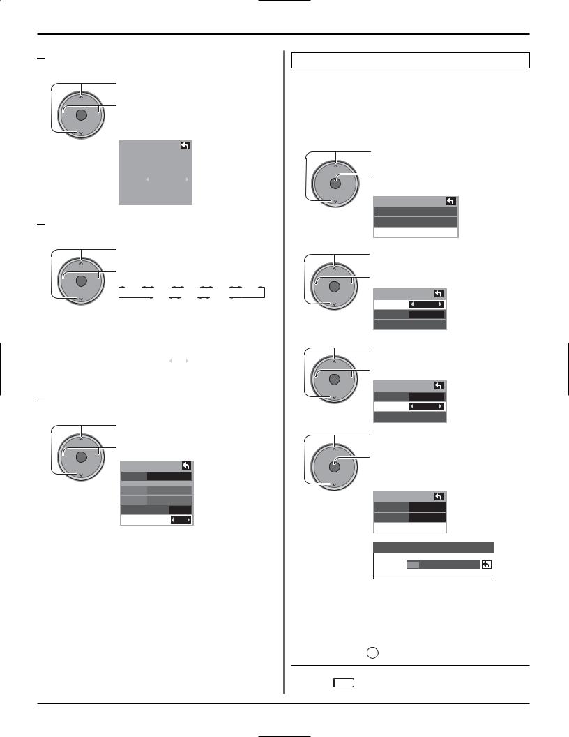
Clock
Press to select “Clock”.
CH
Press to display the clock adjust screen.
-VOL OK VOL+
First Time Setup
Language
Clock
Auto program
Language
Language English
Language
Language English
First Time Setup
Language
Clock
Auto program
CH

 Mode
Mode
CH
-VOL OK VOL+
CH
Press to select “Mode”.
Press to select “Manual” or “Auto”. Manual : Registers the time set by user.
Auto : Updates the clock time by extracting time information from the digital broadcast.

 Date
Date
Valid when Mode is set to manual.
Press to select “Date”.
|
CH |
Press and release immediately to change the day; press |
|
|
|
-VOL |
OK VOL+ |
and hold to change the month. |
|
||
|
CH |
|
Clock
|
Mode |
|
Manual |
|
||
|
|
|
|
|||
|
Date |
4 / 1 / 2005 |
|
|||
|
|
|
|
|||
|
Time |
|
9 : 43 AM |
|
||
|
|
|
|
|||
|
Time zone |
|
EST |
|
||
|
|
|
|
|
||
|
DST |
|
|
Off |
|
|
|
|
|
|
|
|
|
|
Clock |
|
|
|
|
|
|
|
|
|
|
|
|
|
Mode |
|
Manual |
|
||
|
|
|
|
|||
|
Date |
4 / 1 / 2005 |
|
|||
|
|
|
|
|
|
|
|
Time |
|
9 : 43 AM |
|
||
|
Time zone |
|
EST |
|
||
|
DST |
|
|
Off |
|
|
18
First time setup

 Time
Time
Valid when Mode is set to manual.
CH
-VOL OK VOL+
CH
Press to select “Time”.
Press to adjust “Time”.
If the button is held, the speed of change increases.
Clock
Mode |
|
Manual |
|
|
|
||
Date |
4 / 1 / 2005 |
||
|
|
|
|
Time |
|
9 : 43 AM |
|
|
|
|
|
Time zone |
|
EST |
|
|
|
|
|
DST |
|
|
Off |

 Time zone
Valid when Mode is set to “Auto”.
Press to select “Time zone”.
CH
Press to select your zone.
-VOL OK |
VOL+ |
|
|
|
|
|
AST |
EST |
CST |
MST |
PST |
CH |
|
NST |
HST |
AKST |
|
|
|
|
Clock |
|
|
|
|
|
|
|
|
|
Mode |
|
Auto |
||
|
|
|||
Date |
4 / 1 / 2005 |
|||
Time |
|
9 : 43 AM |
||
Time zone |
|
EST |
||
|
|
|
|
|
DST |
|
|
Off |
|

 Daylight saving
Valid when Mode is set to “Auto”.
Press to select “DST” (Daylight saving).
CH
Press to select “On” or “Off”.
-VOL OK VOL+
Clock
CH |
|
|
Mode |
|
Auto |
Date |
4 / 1 / 2005 |
|
Time |
|
9 : 43 AM |
Time zone |
EST |
|
DST |
|
Off |
Auto program
Auto program is not available while the CableCARDTM is inserted.
You can scan All (Analog and Digital) channels. If needed, follow the menus and procedures displayed on-screen for setting up the features.
You can also adjust the settings in Setup menu.
1 |
Press to select “Auto program”. |
|
|
|
CH |
-VOL OK VOL+
CH
2
CH
Press to display “Auto program” adjust screen.
First time setup
Language
Clock
Auto program
Press to select “ANT In”.
Press to select “Cable” or “Antenna”.
-VOL OK VOL+
CH
3
CH
-VOL OK VOL+
CH
4
CH
-VOL OK VOL+
CH
Auto program
ANT In |
Cable |
Mode All
Start scan
Press to select “Mode”.
Press to select “All” or “Analog ”.
Auto program
ANT In |
Cable |
Mode |
All |
Start scan |
|
Press to select “Start scan”.
Press to start.
Channels available for reception will be set automatically.
Auto program
ANT In |
Cable |
Mode |
All |
Start scan |
|
Now scanning analog channel ...
Progress
•After Auto program is complete, the unit will return to Manual Program mode.
To make available a channel that has been located by auto scan, in the Manual program mode, move the cursor to “Apply” and pressOK key.
Press EXIT : To exit the menu screen
19

First time setup
INITIAL GUIDE SETUP for TV Guide
The TV Guide Welcome Screen is displayed at first time setup. Follow the guidance shown on the screen.

 Reminder Screen
If you previously skipped TV Guide setup, you see the
Reminder Screen when you power On your TV.
CH
-VOL OK VOL+
Move the highlighting to select an option.
Press OK to choose the option.
CH
• Set up TV Guide On Screen now |
: TV Guide setup begins. Follow the instructions on the screen to perform setup. |
|
|
|
(See page 49, INITIAL GUIDE SETUP for TV Guide) |
• |
Remind me to set it up later |
: The system returns to the normal TV screen. |
• |
Don’t remind me again |
: The system returns to the normal TV screen. The Reminder Screen will no longer |
|
|
be displayed when power is turned On. |
Note:
If you decide not to setup the TV Guide now, this reminder screen will appear each time you power On the TV (except if you selected “Don’t remind me again”).

 Welcome Screen
The Welcome Screen is displayed at first time setup.
CH
-VOL OK VOL+
CH
Press OK to begin TV Guide setup. Follow the instructions on the screen to perform setup.
(See pages 49-51)
20
Watching TV programs
POWER
SAP
LIGHT
TV VCR DVD
DTV RCVR DBS/CBL AUX
TV/VIDEO  SLEEP EXIT
|
|
ECT |
FAV |
O |
RIT |
|
P |
|
|||
S |
|
|
|
||
A |
|
|
|
|
E |
|
|
|
E |
|
R |
|
|
|
|
C |
|
|
U |
T |
|
|
E |
M |
|
CH |
A |
||
|
|
L |
|||
|
|
|
|
|
L |
|
|
|
|
-VOL OK VOL+ |
|
MENU |
CH |
RETURN |
|||
1
2
3
TV |
Press to operate the TV set with the remote control. |
POWER |
SETUP SCHEDULE LISTINGS SEARCH SETUP |
|
Press to turn the TV on. |
|
TV Guide is displayed. |
|
Please refer to page 43 for the TV Guide |
|
description and operating instruction. |
EXIT |
Press to exit from the TV Guide on screen display. |
|
TVGUIDE INFO |
PAGE |
4
CH
-VOL OK VOL+
CH
Press channel up/down buttons to tune to the desired channel.
•You can also use the direct program number selection buttons and PROG–button (see page 17).
Select the desired volume level.
NOTE: The factory default setting is to display the TV Guide channel list whenever the TV is initially powered On.
To disable this default mode and view a TV channel on every power on, perform the following operations.
1 Press ‘TV Guide’ remote button & select “SETUP” in the Service Bar of the TV Guide.
LISTINGS |
SEARCH |
SETUP |
SCHEDULE |
LISTINGS |
2
CH
-VOL OK VOL+
CH
3
CH
-VOL OK VOL+
CH
4
CH
-VOL OK VOL+
CH
5
CH
-VOL OK VOL+
Press to select “Change default options”.
Press to display “Change default options”.
Press to select “General defaults”.
Press to display “General defaults” in Panel Menu.
Press to select “auto guide”.
Press to select “off”.
Press to select “done”.
Press to store the “setup”.
TV Guide channel listing will no longer appear.
LISTINGS |
SEARCH |
SETUP |
SCHEDULE |
LISTINGS |
LISTINGS |
SEARCH |
SETUP |
SCHEDULE |
LISTINGS |
CH
21
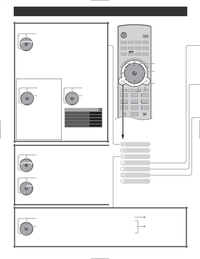
On-Screen Menu Displays for Navigation
Picture adjust (See page 24)
Press to select picture menu.
CH
 Press to select or
-VOL OK VOL+
adjust picture CH items.
|
Picture 1/2 |
|
|
|
|
Normal |
No |
|
|
|
Pic. mode |
Standard |
|
|
|
Picture |
+30 |
|
|
|
Brightness |
0 |
|
|
|
Color |
0 |
|
|
|
Tint |
0 |
|
|
|
Sharpness |
+10 |
|
|
|
|
|
|
|
|
|
|
|
|
|
Picture 2/2 |
|
|
|
|
Color Temp |
Cool |
|
|
|
Color Mng. |
Off |
|
|
|
C.A.T.S. |
Off |
|
|
|
Zoom Adjust |
|
|
|
|
PC Adjust |
|
|
|
|
Other Adjust |
|
|
|
|
|
|
|
|
During “RGB / PC” input signal.
Press to select “PC Adjust”.
CH |
Press to display |
||||
-VOL OK VOL+ |
|||||
PC Adjust |
|||||
|
|||||
CH |
menu. |
||||
|
|||||
|
|
|
|
|
|
PC Adjust 1/2 |
|
|
|
|
|
Normal |
|
No |
|
||
Sync |
|
On G |
|
||
Dot Clock |
|
0 |
|
||
H-Position |
|
0 |
|
||
V-Position |
|
0 |
|
||
|
|
|
|
|
|
PC Adjust 2/2 |
|
|
|
|
|
Clock Phase |
|
0 |
|
||
Input Resolution |
|
VGA |
|
||
|
|
|
|
|
|
Press to select “Other Adjust”.
CH |
Press to display |
|
-VOL OK VOL+ |
||
Other Adjust |
||
|
||
CH |
menu. |
|
|
||
Other Adjust |
|
|
Video NR |
Off |
|
3D Y/C Filter |
Off |
|
Color Matrix |
SD |
|
MPEG NR |
Off |
|
Black level |
Dark |
POWER
|
|
|
SAP |
|
|
|
|
|
LIGHT |
|
|
TV |
VCR |
DVD |
|
|
|
DTV |
RCVR |
DBS/CBL |
AUX |
|
|
TV/VIDEO |
|
SLEEP |
EXIT |
|
|
|
T |
|
|
|
|
|
|
|
|
Press to select. |
|
-VOL OK |
VOL+ |
Press to enter each |
|||
adjust screen. |
|||||
|
|
|
|
||
MENU |
CH |
|
RETURN |
|
|
|
|
|
|
Press to return to |
|
TVGUIDE |
INFO |
PAGE |
previous menu. |
||
1 |
2 |
|
3 |
|
|
4 |
5 |
|
6 |
|
|
7 |
8 |
|
9 |
|
|
R-TUNE |
0 |
|
PROG |
|
|
|
|
|
|
||
MENU
 Press
Press  button to display main menu.
Audio adjust (See page 27) Press to select Audio menu.
CH
 Press to adjust
-VOL OK VOL+
Audio items.
CH
Press to select “Other Adjust”.
CH
 Press to display
-VOL OK VOL+
Other Adjust
CH
menu.
|
|
|
|
|
|
|
Picture |
|
||
|
|
|
|
|
|
|
|
|||
|
|
|
|
|
|
|
Audio |
|
|
|
|
|
|
|
|
|
|
|
|
|
|
|
|
|
|
|
|
|
|
|
|
|
Audio |
|
|
|
|
|
|
Timer |
|
||
Normal |
Set |
|
|
|
|
|
|
|
|
|
Bass |
+ 7 |
|
|
|
|
Lock |
|
|||
Treble |
+ 7 |
|
|
|
|
|
|
|
|
|
Balance |
0 |
|
|
|
|
Memory card |
|
|||
Other Adjust |
|
|
|
|
|
|
|
|
|
|
|
|
|
|
|
|
|
TV Guide |
|
||
Other Adjust |
|
|
|
|
|
|
|
|
|
|
AI Sound |
On |
|
|
|
|
Setup |
|
|
||
BBE VIVA 3D |
On |
|
|
|
|
|
|
|
|
|
BBE |
On |
|
|
|
|
|
|
|
|
|
Surround |
Off |
|
|
|
|
|
|
|
|
|
Speakers |
On |
|
|
|
|
|
|
|
|
|
HDMI In |
Auto |
|
|
|
|
|
|
|
|
|
Audio Leveler |
0 |
|
|
|
|
|
|
|
|
|
|
|
|
|
|
|
|
|
|
|
|
Timer adjust (See page 28)
Press to select either “Sleep” or “Timer 1” - “Timer 5”.
CH
Press to display desired Timer Adjust menu.
-VOL OK VOL+
CH
Timer |
|
|
|
Sleep |
|
|
Sleep |
|
Sleep |
60 |
|
||
Timer 1 |
|
|
|
|
||
|
|
|
|
|||
Timer 2 |
|
|
|
|
||
Timer 3 |
|
Timer 1 |
|
|
||
Timer 4 |
|
CH |
310 - 1 |
|||
Timer 5 |
|
Day |
EVR FRI |
|||
|
|
|
|
On time |
10:00 AM |
|
|
|
|
||||
|
|
|
|
Off time |
11:00 AM |
|
|
|
|
|
Set |
On |
|
|
|
|
|
|
|
|
22

On-Screen Menu Displays for Navigation
1 |
2 |
3 |
Lock settings |
4 |
5 |
6 |
(See page 35) |
7 |
8 |
9 |
|
|
0 |
|
|
|
|
|
Press to select. |
|
CH |
|
Press to go to each |
|
-VOL OK |
VOL+ |
|
|
setting screen. |
||
|
|
|
CH
Enter a 4-digit password.
Create password. |
Enter password. |
- - - - |
- - - - |
Channel lock
Channel lock |
|
|
|
Program lock |
|
|
|
CH 1 |
|
3 - 0 |
|
|
MPAA |
|
|
CH 2 |
|
|
|
|
U.S.TV |
|
|
CH 3 |
|
|
|
|
C.E.L.R. |
|
|
CH 4 |
|
|
|
|
C.F.L.R. |
|
|
CH 5 |
|
|
|
|
Monitor out |
On |
|
CH 6 |
|
|
|
|
|
|
|
CH 7 |
|
|
|
|
|
|
|
|
|
|
|
|
|
|
|
Lock
Mode Off
Channel
Program
Change password
Change password
Enter new password.
- - - -
Enter new password, again.
- - - -
Photo Viewer for Memory CARD (See page 39) |
JPEG thumbnail |
|
|
|
||||
|
|
Press to select “SD card” |
|
Info |
|
|
|
|
|
|
|
|
Total 8 |
|
|
|
|
|
|
or “PC card”. |
|
No. |
102-0006 |
102-0001 |
102-0002 |
102-0003 |
|
|
SD card |
|
|
|
|||
|
|
Pixel |
2048x1536 |
|
|
|
||
|
|
|
|
Date |
01/01/2000 |
|
|
|
CH |
|
Press to enter |
PC card |
|
|
|
|
|
-VOL OK |
VOL+ |
|
|
102-0004 |
102-0005 |
102-0006 |
||
the Photo Viewer. |
|
Select OK |
|
|
|
|||
|
|
|
Select |
|
|
|
|
|
CH |
|
|
|
MENU |
RETURN |
102-0007 |
102-0008 |
|
TV Guide
(See page 43)
SETUP |
SCHEDULE |
LISTINGS |
SEARCH |
SETUP |
CH
-VOL OK VOL+
CH
Press to move the highlighting.
Press to choose the option and continue to the next mode.
Setup (See page 29)
Setup |
|
Setup |
CH |
CH scan |
|
Other adjust |
|
Fav. |
|
||
Language |
|
About |
-VOL OK VOL+ |
|
Reset |
|
|
Clock |
|
CH |
|
|
|
|
|
Program channel |
|
|
|
Input labels |
|
|
RETURN |
CC |
|
|
|
Language |
|
Language |
|
|
|
|
|
|
Program |
|
(See page 18) |
|
Language |
|
English |
|
|
channel |
|||
|
|
|
|
|
|
|
|
|
|
(See page 30) |
|
|
|
|
|
|
|
|
|
|
|
Clock adjust |
|
|
|
|
|
|
|
|
|
CC |
|
Clock |
|
|
|
|
|
||||
(See pages 18, 19) |
|
Mode |
|
Manual |
|
|
|
(Closed Caption) |
||
|
|
Date |
|
4 / 1 / 2005 |
|
|
|
(See page 32) |
||
|
|
Time |
9 : 43 AM |
|
|
|
|
|||
|
|
Time zone |
|
EST |
|
|
|
|
||
|
|
DST |
|
Off |
|
|
|
|
||
Input Labels |
|
|
|
|
Other Adjust |
|||||
|
Input labels |
|
|
|||||||
(See page 32) |
|
|
|
|
|
|
|
|
|
(Setup) |
|
Comp. 1 |
|
|
|
|
|
||||
|
|
|
|
|
|
|
|
|||
|
Comp. 2 |
|
|
(See page 34) |
|
|
|
|
|
|
HDMI |
|
|
|
|
|
|
|
|
|
|
|
|
|
|
Video 1 |
|
|
About |
|
|
|
|
|
|
Video 2 |
|
|
(See page 34) |
|
|
|
|
|
|
Video 3 |
|
|
|
|
|
|
|
|
|
|
|
|
|
|
Input labels |
|
|
|
|
PC |
|
|
|
|
|
|
|
|
Press to select .
Press to go to each adjust screen.
Press to return to |
Auto program (See page 30) |
|||||
Auto program |
|
|
||||
previous screen. |
ANT In |
Cable |
|
|
||
|
|
Mode |
All |
|
|
|
|
|
Start scan |
|
|
|
|
Program channel |
Manual program (See page 30) |
|||||
Auto |
|
|||||
Manual |
|
|
|
Edit |
Apply |
|
Signal meter |
CH |
Caption |
Favorite |
Add |
||
|
|
1 |
- - - |
- - - |
No |
|
CC |
|
2 |
|
2 |
Yes |
|
Mode |
Off |
3 |
- - - |
- - - |
No |
|
Analog |
CC1 |
4 |
- - - |
- - - |
No |
|
Digital |
Primary |
5 |
- - - |
- - - |
No |
|
Digital setting |
6 |
- - - |
- - - |
No |
||
|
|
|
|
|||
|
|
7 |
- - - |
- - - |
No |
|
CC reset |
|
8 |
- - - |
- - - |
No |
|
|
|
|||||
Other Adjust |
9 |
- - - |
- - - |
No |
||
10 |
- - - |
- - - |
No |
|||
|
|
|||||
|
Auto Power On |
Off |
|
|
|
|
|
|
|
|
|
|
|
|
|
|
|
Signal meter (See page 31) |
|||||||||||||
|
|
|
|
|
|||||||||||
|
Side Bar |
Off |
|||||||||||||
|
|
|
|
||||||||||||
|
|
|
|
|
|
|
|
|
|
|
|
|
|
||
|
|
|
|
|
Signal meter |
|
|
|
|
|
|
|
|||
|
About |
|
|
|
CH |
|
2 - 1 |
|
|
|
|
|
|
||
|
Version |
|
|
|
|
|
|
|
|
|
|
|
|
|
|
|
|
|
Signal strength |
|
|
|
|
|
|||||||
|
License |
|
|
|
|
|
|
|
|||||||
|
|
|
|
|
|
|
|
|
|
|
|
|
|
||
|
CableCARD |
|
|
Current |
85 % |
|
|
|
|
|
|||||
|
|
|
|
|
Peak level |
85 % |
|
|
|
|
|
||||
|
|
|
|
|
|
|
|
|
|
|
|
|
|
|
|
23
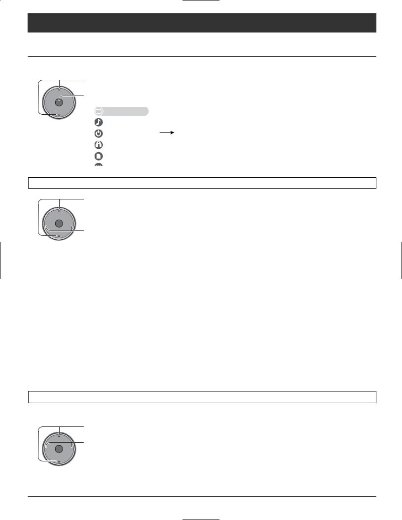
Menu Navigation
Picture
Press the MENU button to display the Main menu.
Press to select “Picture”.
CH
Press to enter sub-menu.
-VOL OK VOL+
CH
Picture |
|
Picture 1/2 |
|
|
|
Picture 2/2 |
|
|
|
|
|
|
|
|
|
|
|
|
|
Normal |
No |
|
Color Temp |
Cool |
||
Audio |
|
Pic. mode |
Standard |
|
Color Mng. |
Off |
||
Timer |
|
Picture |
+30 |
|
C.A.T.S. |
Off |
||
|
Brightness |
0 |
|
Zoom Adjust |
|
|
||
|
|
|
|
|
||||
Lock |
|
Color |
0 |
|
PC Adjust |
|
|
|
Memory card |
|
Tint |
0 |
|
Other Adjust |
|
|
|
|
Sharpness |
+10 |
|
|
|
|
||
|
|
|
|
|
|
|||
|
|
|
|
|
|
|
|
|
Normal / Picture / Brightness / Color / Tint / Sharpness / Color Temp / Color Mng. / C.A.T.S
CH
-VOL OK VOL+
CH
Press to select the sub-menu.
Press to adjust the sub-menu.
Picture 1/2 |
|
|
|
Picture 2/2 |
|
|
|
|
|
|
|
|
|
Normal |
No |
|
Color Temp |
Cool |
||
|
|
|
|
|
|
|
Pic. mode |
Standard |
|
Color Mng. |
Off |
||
Picture |
|
|
|
C.A.T.S |
|
|
+30 |
|
Off |
||||
|
|
|
|
|
|
|
Brightness |
0 |
|
Zoom Adjust |
|
|
|
|
|
|
|
|
|
|
Color |
0 |
|
PC Adjust |
|
|
|
|
|
|
|
|
|
|
Tint |
0 |
|
Other Adjust |
|
|
|
|
|
|
|
|
|
|
Sharpness |
+10 |
|
|
|
|
|
|
|
|
|
|
|
|
Item |
Explanations |
||
Normal |
Resets all picture adjustments to factory default settings. |
||
Picture |
Adjusts white areas of picture. |
|
|
Brightness |
Adjusts dark areas of picture. |
|
|
Color |
Adjusts desired color intensity. |
|
|
Tint |
Adjusts natural fresh tones. |
|
|
Sharpness |
Adjusts clarity of outline detail. |
|
|
Color Temp |
To increase or decrease Warm (red) and Cool (blue) colors to suit personal preferences. |
|
|
(Temperature) |
|||
Color Mng. |
Color Mng. On enhances green and blue color reproduction, especially outdoor scenes. |
||
(Color Management) |
|
|
|
C.A.T.S. |
Plasma C.A.T.S. (Contrast Automatic Tracking System) automatically senses the ambient light conditions |
||
and adjusts the brightness and gradation accordingly, to optimize contrast. |
|||
|
|||
|
|
|
|
Pic. mode
Choose the pre-set picture mode that best suits the program you are viewing. This feature also affects Color Temp setting.
Press to select “Pic. mode”.
CH
-VOL OK VOL+
CH
Press to select the picture mode.
• |
Vivid (default) : Provides enhanced picture contrast and sharpness for viewing in a well-lit room. |
|
• Standard |
: Recommended for normal viewing conditions with subdued room lighting. |
|
• |
Cinema |
: For watching movies in a darkened room. It provides a soft, film-like picture. |
Note: Each mode has its own picture settings (Picture, Brightness, Color, Tint and Sharpness).
24

Menu Navigation
Zoom Adjust
Adjust the Zoom position.
It works when Aspect mode is Zoom.
Press to select Zoom Adjust
menu.
CH
Press to display the Zoom Adjust
-VOL OK |
VOL+ |
screen. |
|
|
|
CH |
|
|
Picture 1/2 |
|
|
|
Picture 2/2 |
|
|
Normal |
No |
|
Color Temp |
Cool |
||
Pic. mode |
Standard |
|
Color Mng. |
Off |
||
Picture |
+30 |
|
C.A.T.S |
Off |
||
|
|
|
|
Zoom Adjust |
|
|
Brightness |
0 |
|
|
|||
Color |
0 |
|
PC Adjust |
|
|
|
Tint |
0 |
|
Other Adjust |
|
|
|
Sharpness |
+10 |
|
|
|
|
|
|
|
|
|
|
|
|
|
|
Press to adjust V-Position. |
|
|
CH |
Press to adjust Size. |
|
|
|
||
-VOL |
OK VOL+ |
• V-Position : Adjust the vertical |
|
|
|
||
|
CH |
|
position. |
|
|
• Size |
: Adjust the vertical |
|
|
|
size. |
Note:
To return to the default setting, press the “OK” button.
V-Position Adjust the vertical position.
|
CH |
|
-VOL OK VOL+ |
|
CH |
Size |
Adjust the vertical size. |
|
CH |
|
-VOL OK VOL+ |
|
CH |
Other Adjust
CH
-VOL OK VOL+
CH
CH
-VOL OK VOL+
CH
Press to select “Other Adjust”.
Press to display other Adjust menu.
Press to select the sub-menu.
Press to select or adjust the submenu.
Picture 1/2 |
|
|
|
Picture 2/2 |
|
|
|
|
|
|
Color Temp |
Cool |
|
Normal |
No |
|||||
Pic. mode |
Standard |
|
Color Mng. |
Off |
||
Picture |
+30 |
|
C.A.T.S |
Off |
||
Brightness |
0 |
|
Zoom Adjust |
|
|
|
Color |
0 |
|
PC Adjust |
|
|
|
Tint |
0 |
|
Other Adjust |
|
|
|
Sharpness |
+10 |
|
|
|
|
|
|
|
|
|
|||
|
|
|
|
|
|
|
|
|
|
|
|
|
|
|
|
|
|
Other Adjust |
|
|
|
|
|
|
|
|
|
|
|
|
|
Video NR |
Off |
|
|
|
|
|
|
|
|
|
|
|
|
3D Y/C Filter |
Off |
|
|
|
|
|
|
|
|
|
|
|
|
Color Matrix |
SD |
|
|
|
|
|
|
|
|
|
|
|
|
MPEG NR |
Off |
|
|
|
|
|
|
|
|
|
|
|
|
Black level |
Dark |
|
|
|
|
|
|
|
|
Item
Video NR
3D Y/C Filter
Color Matrix
MPEG NR
Black level
Explanations
Reduces noise, commonly called snow. Leave off when receiving a strong signal.
Minimizes noise and cross-color in the picture.
Select SD or HD.
•SD : When the input signal is a normal TV system (NTSC).
•HD : When the input signal is a High-Definition system (ATSC).
Displays 480p input signals in natural color from digital equipment adapters connected to COMPONENT VIDEO INPUT (Y, PB, PR) terminals.
Select HD or SD to adjust color parameters automatically for HD (high definition) or SD (standard definition).
Note:
This feature is available only with 480p signal and not available with regular TV (NTSC) program.
Digital noise unique to DVD, STB, etc. will be reduced.
Select Dark or Light.
Valid only for external input signals.
25
Loading...