


Panasonic TH-55LF60U, TH-55LF6U, TH-47LF6U, TH-47LF60U, TH-42LF6U User Manual
...Operating Instructions
FULL HD LCD Display
Model No.
TH-42LF6U TH-42LF60U TH-47LF6U TH-47LF60U TH-55LF6U TH-55LF60U
|
Before connecting, operating or adjusting this product, |
|
|
|
|
|
|
|
|
English |
|
|
|
|
|
please read these instructions completely. |
|
|
|
|
Please keep this manual for future reference. |
|
|
|
CAUTION
RISK OF ELECTRIC SHOCK
DO NOT OPEN
WARNING: To reduce the risk of electric shock, do not remove cover or back.
totell the user that parts inside the product are a risk of electric shock to persons.
triangleis intended to tell the user that important operating and servicing instructions are in the
WARNING : moisture.
! " # ! # "
WARNING $%" & # ' ( )
*" )
( ( ture.
+( # Do not defeat the purpose of the grounding plug.
2

Important Safety Instructions
%" '
*" Keep these instructions.
-" /
0" 1
2"
3" 4
5" # + ( 6
7" ! "
8" ( ( ( 9 #9 # # ( ( +( (( #
%;" < ( #(
%%" = > # (
%*" ? # # # (@ > # A (
%-" ? ( (
%0" ' ( ) E ) # ) # #A (# #
%2" 94
3

Dear Panasonic Customer
Welcome to the Panasonic family of customers. We hope that you will have many years of enjoyment from your new LCD Display.
! !
Visit our Panasonic Web Site http://panasonic.net
Table of Contents
Important Safety Instructions................................... |
3 |
FCC STATEMENT....................................................... |
5 |
Safety Precautions .................................................... |
6 |
Maintenance............................................................... |
7 |
Accessories ............................................................... |
8 |
9 E ............................................. |
8 |
' 4 I ....................................... |
8 |
Ceiling Suspension ................................................... |
9 |
Connections............................................................. |
10 |
94 # .................... |
10 |
Video equipment connection ................................. |
11 |
9? += =? ....................................... |
12 |
HDMI connection.................................................. |
13 |
T+ W= 4=X<=&W& 'YI +& ... |
14 |
T+ +& T+ =? ........................ |
15 |
PC Input Terminals connection............................. |
16 |
EW'+9^ .............................. |
17 |
+' +& > +' =? ................... |
18 |
W +Y+ 9^ ^+&` |
|
Terminal................................................................ |
19 |
Power ON / OFF ....................................................... |
20 |
Selecting the input signal....................................... |
22 |
Basic Controls ......................................................... |
23 |
ASPECT Controls .................................................... |
25 |
Digital Zoom............................................................. |
26 |
On-Screen Menu Displays ...................................... |
27 |
Adjusting POS. /SIZE .............................................. |
28 |
PICTURE Adjustments ............................................ |
30 |
9 T9&4W EW +&YE....................................... |
31 |
SOUND Adjustment................................................. |
32 |
PRESENT TIME SETUP / SET UP TIMER............... |
33 |
<'WEW& +XW EW ?<...................................... |
33 |
EW ?< +XW' .................................................... |
34 |
SCREENSAVER (For preventing image |
|
retention).................................................................. |
35 |
E ( E4'WW&E9TW' ........................... |
36 |
WOBBLING............................................................... |
36 |
NO ACTIVITY POWER OFF ..................................... |
37 |
ECO MODE SETTINGS............................................ |
38 |
Customizing the Input labels.................................. |
39 |
Selecting the On-Screen Menu Language............. |
40 |
Customizing the On-Screen Menu Display ........... |
40 |
SET UP for MULTI DISPLAY.................................... |
41 |
/ X?^ + +E<^9w............................. |
41 |
+ ' 4 1 ................................. |
42 |
SET UP for Input Signals ........................................ |
43 |
4=X<=&W& > 'YI +& EW^W4 ........................ |
43 |
w?T > 'YI +& EW^W4 ........................................ |
43 |
E+Y&9^ ...................................................... |
44 |
- w>4 1+^ W'..................................................... |
44 |
4=^=' EwE WX................................................. |
45 |
3:2 PULLDOWN ................................................... |
45 |
{Y9 X= W .......................................................... |
45 |
&=+EW 'W ?4 +=&............................................ |
46 |
Ew&4 ................................................................... |
46 |
/ X+ '9&YW ...................................................... |
46 |
Input signal display............................................... |
47 |
Network Setup ......................................................... |
48 |
Options Adjustments .............................................. |
51 |
+ E ......................................................... |
53 |
'E *-*4>^9& + ( ........................ |
54 |
Using Network Function ......................................... |
55 |
& 4 ............................................. |
55 |
+Y+ 9^ ^+&` 4 ! |
|
# " .............................. |
56 |
Command Control ................................................ |
57 |
PJLink™ Protocol................................................. |
57 |
Using Web Browser Control................................... |
58 |
I ( ? @ # I 4 ..................... |
58 |
9 ( @ # I ................................... |
58 |
4 !I9E+4 4=& '=^>=< +=& |
|
4=& '=^ E " .............................................. |
59 |
&W @='` EW +&Y !& E E " ... |
60 |
< E !< E E " ....... |
60 |
Crestron Connected™ page................................. |
61 |
Troubleshooting ...................................................... |
63 |
Applicable input signals ......................................... |
65 |
Shipping condition.................................................. |
67 |
......................................... |
68 |
4

FCC STATEMENT
) # ( ( 4 I < %2 ( 144 ' # ( ( residential installation. This equipment generates, uses and can radiate radio frequency energy and, if not installed( ( /( +( ) (( # # ) ((( # ( ($
} |
' |
} |
+ # ) |
} |
4 ) (( ( |
} |
Consult the dealer or an experienced technician for help. |
< %2 ( 144 ' = #A ( $!%"( ( !*" ( interference that may cause undesired operation.
FCC CAUTION:
To assure continued compliance, follow the attached installation instructions and use only shielded interface ! " ! approved by Panasonic Corp. of North America could void the user’s authority to operate this device.
FCC Declaration of Conformity
X & / 0*^13? / 05^13? / 22^13? / 0*^13;? / 05^13;? / 22^13;?
' # < $ < 4 ( & 9 ' ( < & & • ;5%;*
4 E$ < E 4 4 ( & 9 % 7;; 85-0-8;
CANADIAN NOTICE:
4 I 4 +4WE ;;-
NOTE:
Image retention may occur. If you display a still picture for an extended period, the image might remain on the / (
Trademark Credits
} TY9 ( + I X 4
} Microsoft®@®@ T ®, and Internet Explorer® are the registered trademarks or trademarks of X ( 4 ? E >
} X X X =E =E { E ( ( 9 + ? E other countries.
} ETY9 {Y9 E{Y9 ?{Y9 ( T W E 9
} / X+ / X+ ^ / X + ( ( / X+ ^ ^^4 ? E
} ' T 4 ' T 1 'T ( 4 W + Crestron Connected is the trademark of Crestron Electronics, Inc.
W ( # ( # ( respected.
5

Safety Precautions
 CAUTION
This LCD Display is for use only with the following optional accessories. Use with any other type of optional accessories may cause instability which could result in the possibility of injury.
!9 ( ( ( # < 4 "
} Pedestal ............................................................. |
w E 0*<2; !( 0* 05 " |
|
w E 27<*; !( 22 " |
9 # )
E ( ` (#A # > ( # # ( ((
When using the LCD Display
Do not bring your hands, face or objects close to the ventilation holes of the Display.
} ( ( #
I A ( # # < #A( #A ( #
Be sure to disconnect all cables before moving the Display.
} X # #
Disconnect the power plug from the wall outlet as a safety precaution before carrying out any cleaning.
} Electric shocks can result if this is not done.
Clean the power cable regularly to prevent it from becoming dusty.
} I ? (
Note:
} Image retention may occur. If you display a still picture for an extended period, the image might remain on the / (
6

Safety Precautions
WARNING
Setup
Do not place the Display on sloped or unstable surfaces, and ensure that the Display does not hang over the edge of the base.
} The Display may fall off or tip over.
Do not place any objects on top of the Display.
} +( ( #A+( ( #A9 E 4
Do not cover the ventilation holes.
}
Transport only in upright position!
} ( internal circuitry.
$%
Leave a space of 3 15/16” (10 cm) or more at the top, left and right, and 1 31/32” (5 cm) or more at the rear, and also keep the space between the bottom of the ! &
Cautions for Wall Installation
} @ # ( # professional. Installing the Display incorrectly may lead to an accident that results in death or serious A ?
} @ ## (
Caution for Ceiling Suspension
} 4 # ( # installation professional. Installing the Display incorrectly may lead to an accident that results in death or serious injury.
An apparatus with CLASS I construction shall be connected to a mains socket outlet with a protective earthing connection.
Do not install the product to a place where the "
} If the screen is exposed to direct sunlight, the liquid crystal panel may have adverse effect.
AC Power Supply Cord
The Display is designed to operate on 110 - 127 V AC, 50/60 Hz.
Ensure that the mains plug is easily accessible. Do not use any power supply cord other than that provided with this unit.
}
Securely insert the power cord plug as far as it will go.
} +( ( # +( #
Do not handle the power cord plug with wet hands.
} Doing so may cause electric shocks.
Do not do anything that might damage the power cable. When disconnecting the power cable, hold the plug, not the cable.
} #A#A # ( ( ##+( #9 E 4
If the Display will not be used for a long period of time, unplug the power cord from the wall outlet.
If problems occur during use
If a problem occurs (such as no picture or no sound), or if smoke or an abnormal odor is detected from the Display, unplug the power cord immediately.
} Continuous use of the Display under these conditions / 9 E 4 E # personnel are strongly discouraged due to its high voltage dangerous nature.
If water or foreign objects get inside the Display, if the Display is dropped, or if the cabinet becomes damaged, disconnect the power cord plug immediately.
} 9 4 9 E 4 ( #
Maintenance
The front of the Display panel has been specially treated. Wipe the panel surface gently using only a cleaning cloth or a soft, lint-free cloth.
} +( ( ( ( ## %;; ( the surface is dry.
} ( ( #A ( # 1 #) ( ( # ((
If the cabinet becomes dirty, wipe it with a soft, dry cloth.
} +( # ( #? #
} ( ( +(#
} 9 # ) ( # ( # (( (( 1 (( ## <T4
Usage of a chemical cloth
} Do not use a chemical cloth for the panel surface.
} 1 ( ( #
7
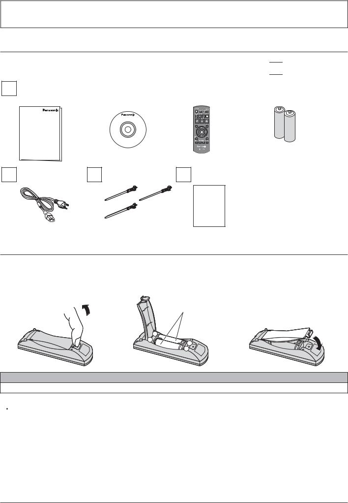
Accessories
Accessories Supplied
Check that you have the Accessories and items shown 

Operating instruction |
|
4 '=X |
|
' |
|
Batteries for the remote |
||||||
# |
|
|
|
!= " |
|
transmitter |
|
control transmitter |
||||
|
|
|
|
|
|
|
|
|
|
&*•9wI;;;38% |
|
!99 E ‚ *" |
|
|
|
|
|
|
|
|
|
|
|
|
|
|
|
|
|
|
|
|
|
|
|
|
|
|
|
|
|
|
|
|
|
|
|
|
|
|
|
|
|
|
|
|
|
|
|
|
|
|
|
|
94 |
4 ‚- |
Warranty card |
|
!1 X " |
|||
|
|
||
|
|
Warranty |
Remote Control Batteries
Requires two AA batteries.
1.Pull and hold the hook, then open #
2. + # |
3. ' |
!ƒ"
„99…
- |
+ |
+ |
|
- |
Helpful Hint:
1 ( ) # 9 # ( (
 Precaution on battery use
+ # ( # # (
Observe the following precautions:
1.I # 9 #
2.# #
3.# !$„ˆ 4 # … „9 …"
4.# # #
5.I
6.# # #
I #
8
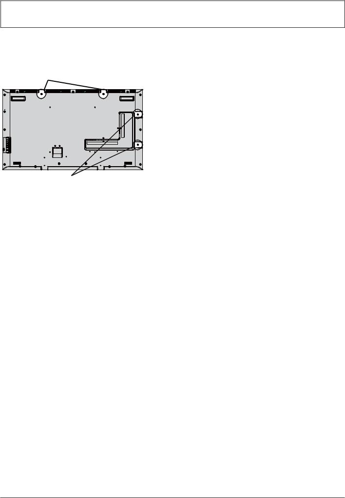
Ceiling Suspension
w # # # !X%;" (! / 22^13? / 22^13;?"
W # |
Note: |
|
!( " |
} |
E # ( # |
|
|
installation professional. |
|
} |
# |
|
} |
@ |
|
|
+ |
|
} |
+ |
|
|
Display. |
W # !( "
9
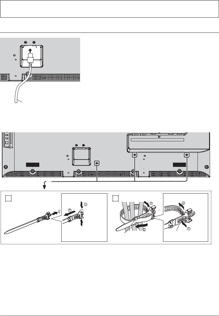
Connections
' "
AC cord (accessory)
Using the clamper
E # )
1 Attach the clamper
hole 
Insert the clamper in a hole.
To remove from the unit:
 snaps
snaps
 Keep # side snaps
2 Bundle the cables |
To loosen: |
|
E |
|
Keep |
|
|
# |
pushing |
||
hooks |
tip in the |
|||
# |
||||
|
||||
|
hooks |
|
|
10
Connections
Video equipment connection
|
|
|
IR IN, IR OUT |
|
|
|
|
|
|
|
|
|
remote control, connects other display |
|
|
|
|
from this IN/OUT port. |
|
|
|
|
( ( |
|
|
|
|
|
|
|
|
|
! %7" |
|
|
|
|
SERIAL IN, SERIAL OUT |
|
|
|
|
EW'+9^ + >= |
|
|
|
|
4 # <4 |
|
|
|
|
! %5" |
|
|
|
|
LAN, DIGITAL LINK |
|
|
|
|
4 +Y+ 9^ ^+&` |
|
|
|
|
|
|
|
|
|
9 |
|
|
|
|
sends video and audio signals via the |
|
|
|
|
+Y+ 9^ ^+&` |
|
|
|
|
! %8 22 23" |
|
|
|
|
AUDIO IN (VIDEO) |
|
|
|
|
Connect the audio output of a device |
|
|
|
|
connected to VIDEO IN. |
|
|
|
|
! %0" |
|
|
|
|
AUDIO IN (COMPONENT / RGB) |
|
|
|
|
Connect the audio output of a device |
|
|
|
|
4=X<=&W& >'YI +& |
|
|
|
|
! %0" |
|
|
|
|
AUDIO IN (DVI-D / PC) |
|
|
|
|
Connect the audio output of a device |
|
|
|
|
T+ +& <4 +& |
|
|
|
|
! %2 %3" |
|
|
|
|
AUDIO OUT |
|
|
|
|
Connect to sound equipment |
|
|
|
|
! %*" |
|
COMPONENT/RGB IN |
VIDEO IN (VIDEO) |
PC IN |
AV IN |
DVI-D IN, DVI-D OUT |
(PR/R, PB/B, Y/G) |
Composite Video |
PC Input |
HDMI 1, HDMI 2 |
T+ + >= |
4 >'YI T + |
Input Terminal |
Terminal |
HDMI Input Terminal |
Terminal |
! %0" |
! %0" |
! %3" |
! %-" |
! %2" |
|
|
|
|
11 |
Connections
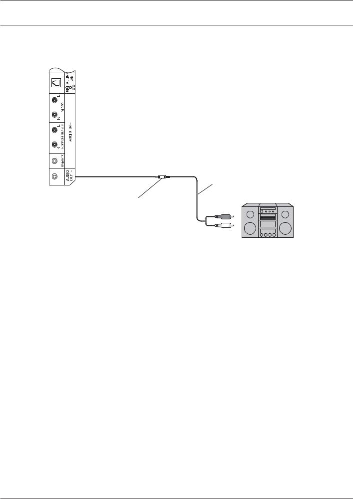
AUDIO OUT connection
Note:
} 9? += =? ( )
} 9 ) #
Stereophonic sound code
audio equipment
Stereo mini plug (M3)
line-in
12
Connections
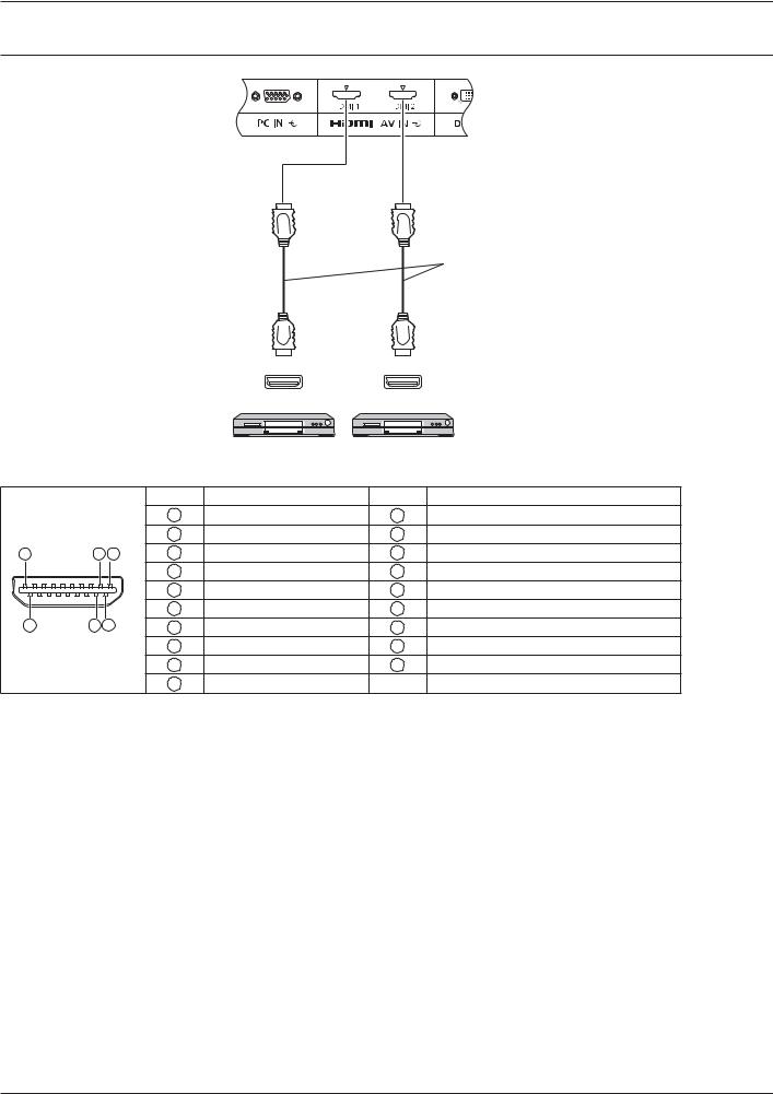
HDMI connection
HDMI cable
HDMI |
HDMI |
AV OUT |
AV OUT |
DVD player DVD player
[Pin assignments and signal names]
|
|
|
|
Pin No. |
E & |
Pin No. |
E & |
|
|
|
|
1 |
X E *ƒ |
11 |
X E 4 E |
|
|
|
|
2 |
X E * E |
12 |
X E 4 • |
|
19 |
3 |
1 |
3 |
X E * • |
13 |
CEC |
|
|
|
|
4 |
X E %ƒ |
14 |
' !& 4 " |
|
|
|
|
5 |
X E % E |
15 |
E4^ |
|
|
4 |
2 |
6 |
X E % • |
16 |
E 9 |
|
18 |
7 |
X E ;ƒ |
17 |
4>4W4 Y |
||
|
|
|
|
8 |
X E ; E |
18 |
ƒ2 T 4 |
|
|
|
|
9 |
X E ; • |
19 |
Hot Plug Detect |
|
|
|
|
10 |
X E 4ƒ |
|
|
Note: |
|
|
|
|
|
|
|
} |
9 ) / X+ # |
||||||
13
Connections
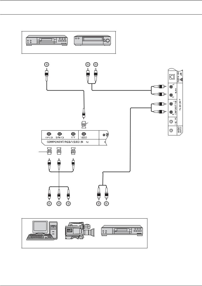
VIDEO, COMPONENT and RGB IN connection
Note: |
|
|
|
} |
9 ) # |
||
|
DVD Player |
VCR |
|
|
VIDEO OUT |
AUDIO OUT |
|
|
|
L |
R |
|
|
|
RCA-BNC |
|
|
|
Adapter plug |
RCA-BNC |
Adapter plug |
Y PB PR OUT |
L |
R |
RGB OUT |
AUDIO OUT |
|
Computer |
RGB Camcorder |
DVD Player |
Notes:
} 4 „4=X<=&W& >'YI +& EW^W4 … „EW ?<… „4=X<=&W& … ! 4=X<=&W&" „'YI… ! 'YI " ! 0-"
} 9 'YI ( 4=X<=&W& >'YI +& „Ew&4 =& Y…
14

Connections
DVI-D IN, DVI-D OUT connection
PC with DVI-D video out
Shared with PC IN. 
DVI-video cable (Within 5 m)
Stereo mini plug (M3)
Daisy chain connection
@ ^4 #
First LCD Display |
Second LCD Display |
PC with DVI-D video out
|
|
Third and |
|
* |
* |
subsequent |
|
LCD displays |
|||
* DVI-video cable |
|
Notes: |
|
|
|
|
|
} |
? %; # # # ( # # |
||||
|
# ) |
|
|
|
|
} |
/ 4< # 7 |
||||
|
DVI-D Input Connector Pin Layouts: |
Pin No. E & |
Pin No. E & |
||
|
|
1 |
X E * • |
13 |
— |
|
|
2 |
X E *ƒ |
14 |
ƒ2 T 4 |
|
|
3 |
X E * E |
15 |
Y |
|
|
4 |
— |
16 |
Hot Plug Detect |
|
|
5 |
— |
17 |
X E ; • |
|
4 |
6 |
DDC Clock |
18 |
X E ;ƒ |
|
|
7 |
DDC Data |
19 |
X E ; E |
|
|
8 |
— |
20 |
— |
|
|
9 |
X E % • |
21 |
— |
|
|
10 |
X E %ƒ |
22 |
X E 4 E |
|
|
11 |
X E % E |
23 |
X E 4ƒ |
|
|
12 |
— |
24 |
X E 4 • |
Note: |
|
|
|
|
|
} |
9 ) # |
|
|
||
|
|
|
|
|
15 |
Connections
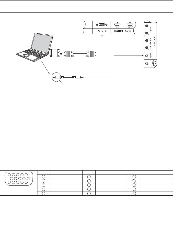
PC Input Terminals connection |
||
|
|
(Female) |
|
COMPUTER |
|
|
Conversion adapter |
|
|
(if necessary) |
(Male) |
|
|
RGB |
|
|
Shared with DVI-D IN. |
|
|
Mini D-sub 15p |
|
Audio |
|
|
|
Stereo mini plug (M3) |
|
Connect a cable which matches |
|
|
the audio output terminal on the computer. |
|
Notes: |
|
|
} |
4 # ( ) (-; %%; / |
|
|
( ) ( 07 %*; / !/ # ( % *;; |
|
|
" |
|
} |
The display resolution is a maximum of 1,440 ‚ %,080 „0$-… % 8*; ‚ % ;7; |
|
|
„1?^^… +( # |
|
|
# ( |
|
} |
<4 4*I # +( # 4*I # |
|
|
need to make setting changes to the computer at the time of connection. |
|
} E <4 #
} ( =E>T # X # %2<
} (
} 9 ) #
} ( ) ( <4 # # frequency range.
Signal Names for Mini D-sub 15P Connector
5 |
|
4 |
3 |
2 |
1 |
Pin No. E & |
Pin No. E & |
Pin No. E & |
||||
|
1 |
' |
6 |
Y& !Y " |
11 |
&4 ! " |
||||||
10 |
9 |
8 |
7 |
6 |
||||||||
2 |
Y |
7 |
Y& !Y " |
12 |
E 9 |
|||||||
15 |
14 |
13 |
12 |
11 |
||||||||
3 |
B |
8 |
Y& !Y " |
13 |
/ >Ew&4 |
|||||||
Pin Layout for PC Input |
||||||||||||
4 |
&4 ! " |
9 |
ƒ2 T 4 |
14 |
VD |
|||||||
|
|
Terminal |
|
5 |
Y& !Y " |
10 |
Y& !Y " |
15 |
E4^ |
|||
16
Connections
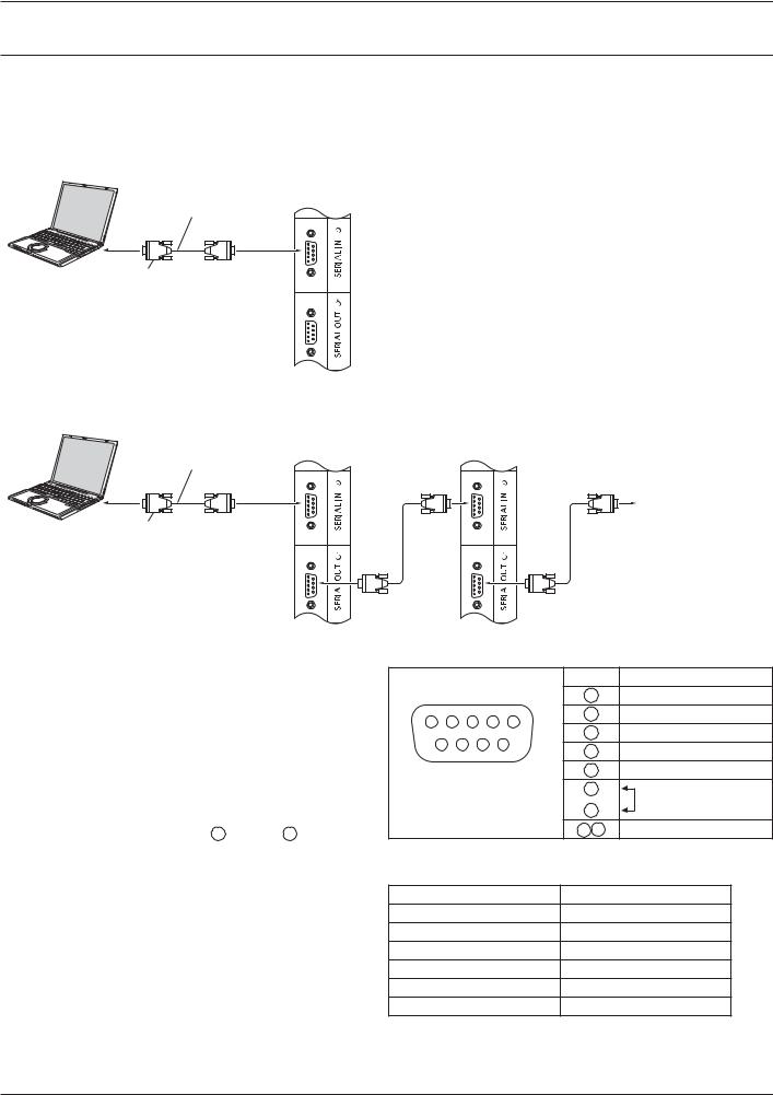
SERIAL Terminals connection
EW'+9^ # |
||
Note: |
|
|
} ( „4=& '=^ +& W'194W… „&W @='` EW ?<… |
||
„'E *-*4 !E "… ! 07" |
|
|
COMPUTER |
|
|
RS-232C Straight cable |
(Male) |
|
|
|
|
(Female) |
|
|
D-sub 9p |
|
|
+ ^4 # <4 ^4 |
||
COMPUTER |
First LCD Display |
Second LCD Display |
|
||
RS-232C Straight cable |
(Male) |
(Male) |
|
|
|
(Female) |
(Female) |
(Female) |
|
|
Third LCD Display |
D-sub 9p |
|
(Male) |
|
|
|
|
(Female) |
(Female) |
Notes: |
Signal names for SERIAL IN terminal: |
|||||||
} |
? 'E *-*4 # |
|
|
|
|
|
Pin No. E & |
|
|
computer to the Display. |
|
|
|
|
|
2 |
'{ |
} |
( |
1 |
2 |
3 |
4 |
5 |
3 |
TXD |
} |
9 ) # |
|
6 |
7 |
8 |
9 |
4 |
' |
|
5 |
Y& |
||||||
|
|
|
||||||
|
|
|
|
|
|
|||
} |
@ „E 4 … |
< ( EW'+9^ |
6 |
E' |
||||
7 |
|
|||||||
|
= ! 2*" |
|
Terminal |
!E " |
||||
|
|
8 |
||||||
} |
1 # |
|
|
|
|
|
|
|
|
|
|
|
|
1 9 |
NC |
||
|
# 2 through 8 . |
|
|
|
|
|
||
EW'+9^ ( 'E *-*4 ( |
( |
|||||||
|
|
|
|
|
|
|
||
# # |
Communication parameters: |
|
||||||
|
E |
|
|
'E *-*4 |
||||
) ( |
E |
9 |
||||||
( |
Baud rate |
|
|
|
83;; # |
|||
# ? |
Parity |
|
|
|
|
None |
|
|
( ' ( |
Character length |
|
7 # |
|
||||
documentation for the computer application for details. |
|
|
||||||
E # |
|
|
|
|
% # |
|
||
|
|
|
|
|
|
|
||
|
|
1 |
|
|
|
|
||
17

Connections
Basic format for control data
The transmission of control data from the computer
E { ( # parameters, and lastly an ETX signal in that order. If there are no parameters, then the parameter signal does not#
E { 
 C1 C2 C3
 :
: 
 P1 P2 P3 P4 P5
 ETX
ETX
|
|
|
|
Colon |
|
< ! " |
|
End |
|
|
|
|
|
|
|||
E |
|
- |
|
!% 2 # " |
!;- " |
|||
|
||||||||
!;* " |
!- # " |
|
|
|
||||
Notes:
} +( # ( ( (# (
} +( # „W'0;%… #
} 4 9 E 4 ( instructions on command usage.
} @ (( <=& command only.
Command
Command |
Parameter |
Control details |
PON |
None |
< =& |
POF |
None |
< =11 |
9T^ |
*** |
T ;;; %;; |
9X |
0 |
9 X? W =11 |
|
1 |
9 X? W =& |
+XE |
None |
+ ! " |
|
9T% |
T+ W= +& !T+ W=" |
|
9T* |
4=X<=&W& >'YI +& |
|
|
!4 " |
|
HM1 |
/ X+% !/ X+%" |
|
HM2 |
/ X+* !/ X+*" |
|
DV1 |
T+ +& ! T+" |
|
PC1 |
<4 +& !<4" |
|
DL1 |
+Y+ 9^ ^+&` |
9X |
None |
E ! " |
|
ˆ==X |
ˆ==X% |
|
FULL |
FULL |
|
&='X |
4:3 |
|
ˆ=X* |
ˆ==X* |
IR IN / IR OUT Terminals connection
?-2 ( 'WX= W =? ( 1 ^4 'WX= W +& ( E ^4 +' ( 1 ^4 # E ^4
First LCD Display |
Second LCD Display |
* |
9 +' ( E ^4
+ # # #

 Third LCD Display
* |
* Stereo mini plug (M3)
18
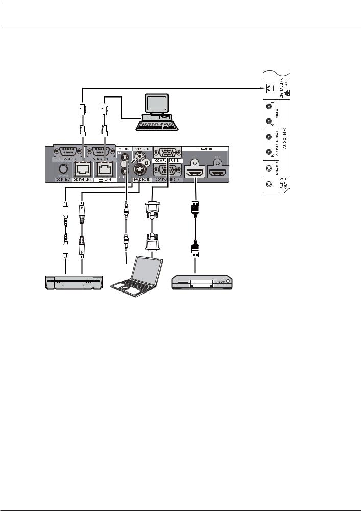
Connections
*" +;<; = =; >
9 # < + ( I !W w1I%;;" ## +Y+ 9^ ^+&` terminal.
Display Connection Terminals
Control
Computer
When a Panasonic ET-YFB100 is used
Video Cassette Recorder |
DVD Player |
Computer
Notes:
} @ +Y+ 9^ ^+&` # ( „& E … ! 07 2;"
} 1 +Y+ 9^ ^+&` „ # … ! 23"
19
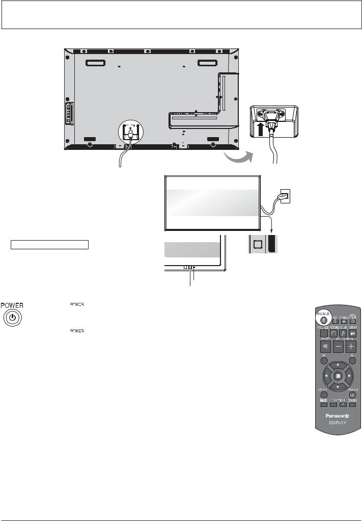
Power ON / OFF
Connecting the AC cord plug to the Display.
Connecting the plug to the Wall Outlet. Notes:
} @ 94 # #94
} < <$< =
Power Indicator: Green

 Power switch
 Power Indicator
Remote Control Sensor
1.Press the  # ((
# ((
Power Indicator: Red (standby)
2.Press the  #
#
Power Indicator: Green
3.(( # 
 #
#
Note:
} ( (((
20
Power ON / OFF
?
1 # ( E ? #
OSD LANGUAGE |
|
|
1. |
E |
OSD LANGUAGE |
|
|
English (UK) |
2. |
E |
Deutsch |
|
|
Français |
|
|
Italiano |
|
|
Español |
|
|
ENGLISH (US) |
|
|
˜™šš›œ• |
PRESENT TIME SETUP
1. E „ 9w… „<'WEW& +XW =1 9w…
 2. E „ 9w… „<'WEW& +XW =1 9w…
 PRESENT TIME SETUP
PRESENT TIME OF DAY |
MON 99 : 99 |
|
|
|
|
SET |
|
|
|
|
|
DAY |
MON |
|
|
|
|
PRESENT TIME OF DAY |
99 : 99 |
|
1. E „EW …

 2. E
2. E
PRESENT TIME SETUP |
|
PRESENT TIME OF DAY |
MON 99 : 99 |
SET |
TUE |
DAY |
|
PRESENT TIME OF DAY |
10 : 00 |
Notes:
} |
= 6 # |
} |
9( # ( |
|
=E ^9&Y?9YW ! 0;" |
|
<'WEW& +XW EW ?< !--" |
Power ON warning message
( # =&$
No activity power off Precautions
6&= 94 +T+ w <=@W' =116 +E W&9I^W
+( „&= 94 +T+ w <=@W' =11… EW ?< „W&9I^W…=& !-5"
# ($ |
= |
|
< = X ! 2-" |
21
 Loading...