


10th Generation Full High Definition Plasma Display TV
This Seminar covers the Full High Definition Models TH-42/50/58PZ700U and TH-50/58PZ750U
Panasonic Services Company
National Training

Prepared by
Cesar Perdomo
Panasonic Service and Technology Company
National Training
Copyright © 2007 by Panasonic Services Company
All rights reserved. Unauthorized copying and distribution is a violation of law.
! Warning
This service information is designed for experienced repair technicians only and is not designed for use by the general public. It does not contain warnings or cautions to advise non-technical individuals of potential dangers in attempting to service a product. Products powered by electricity should be serviced or repaired only by experienced professional technicians. Any attempt to service or repair the product or products dealt with in this service information by anyone else could result in serious injury or death.
Table of Contents
Subject |
Page # Subject |
Page # |
Features |
7 |
|
Power On (Multi-Circuit) |
52 |
|
Models Comparison |
8 Power On (Actual Commands Path) |
54 |
|||
High Resolution (FULL-HD Panel) |
9 |
|
Power On (Vsus-Circuit) |
56 |
|
Difference between the PZ700U & PZ750U |
10 |
|
Method to Drive Only the Panel Drive Circuit |
58 |
|
TH-50/58PZ700U Board Layout & |
13 |
|
Circuit Operation When D3 Is Disconnected |
60 |
|
Description |
|
|
|
|
|
TH-42PZ700U Board Layout |
14 |
|
D3 Location |
62 |
|
TH-50/58PZ750U Board Layout |
15 |
|
SOS Detect Circuit (D Board) |
|
65 |
Boards Name |
17 |
|
P15V Distribution |
69 |
|
TH-58PZ750U Board Layout (Pictorial) |
18 |
|
P5V Distribution |
71 |
|
Power Supply (Standby) |
21 |
|
Vda Voltage Distribution |
73 |
|
Standby (TH-58PZ750U) |
24 |
|
Drive Reset (TH-50/58PZ750U/700U) |
|
75 |
Standby (Main CPU STB5V Supply) |
27 |
|
How To Bypass Drive Reset |
77 |
|
Standby (STB5V Actual Path) |
29 |
|
D9300 (D300) Location(TH-58PZ700U) |
|
79 |
TV_SUB_ON (F_STB_ON) |
31 |
|
Scan/Sustain SOS Detect Circuits |
|
81 |
Standby (TV_SUB_ON (F_STB_ON |
33 |
|
DG Board SOS Detect Circuit |
|
83 |
Distribution) |
|
|
|
|
|
TH-50PZ700U SUB Voltages Circuit (H |
35 |
|
F+15V, DTV9V, SUB5V SOS Detect Circuit |
85 |
|
Board) |
|
|
(10 Blinks) |
|
|
TH-58PZ750U SUB Voltages Circuit (H |
37 |
|
Fan SOS Detect (11 Blinks) |
87 |
|
Board |
|
|
|
|
|
Sub Voltages Distribution Block Diagram |
39 |
|
Sound SOS Detect (12 Blinks) |
89 |
|
Actual Sub Voltages Distribution (TH- |
41 |
|
Video Process (TH-50/58PZ750U) |
93 |
|
58PZ750U) |
|
|
|
|
|
Power On |
43 |
|
Video Process (TH-50/58PZ700U) |
|
96 |
Power On Operation |
44 |
|
Video Process Block Diagram |
|
99 |
Power On Block Diagram |
48 |
|
Signal Process Circuit |
101 |
|
Power On (Commands Path) |
50 |
|
Video Process |
103 |
|
3
Table of Contents (Continued)
Subject |
Page # |
Adjustments |
105 |
Self-Check |
107 |
Self-Check Menu |
108 |
How To Reset |
109 |
Check Point |
110 |
Service-Man Mode |
111 |
Service-Man Mode (Menu) |
112 |
Internal Test Patterns |
113 |
Driver Set-UP Adjustment |
114 |
Initialization Pulse Adjustment |
115 |
4

Topics
Features
Model Differences
Boards Description
Power Supply/System Control
SOS Detect Circuit
Signal Process
Adjustments
Serviceman Mode
5

6

Features
V-real Technology for Ultimate High Picture Quality
• 1080p HD Plasma Panel (1920 x 1080 pixels)
• 1080p Digital Processing Chip-Set
• 1080p Digital Re-mastering Processor |
|
AVCHD/MPEG2 |
|
PC |
|
HDMI |
|
EZ |
|
BBE |
|
/HD-JPEG |
|
|
|
|
|||||
• 4,096 Equivalent Steps of Gradation |
|
Viewer |
|
Input |
|
Input x3 |
|
Sync |
|
VIVA |
• Max. 5,000 : 1 Contrast
• Digital Optimizer
• Cinema Mode (PZ750 models only)
• Advanced 3D Color Management
• Motion Pattern Noise Reduction
• Sub-Pixel Controller
Other Features For Comfortable TVs Life
•EZ Sync
•SDHC Card Networkability (AVCHD/MPEG2/HD-JPEG) (PZ750 models only)
•High Quality Elegant Design
•Advanced Smart Sound Speaker System
•BBE VIVA
7
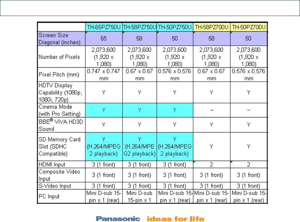
Models Comparison
8
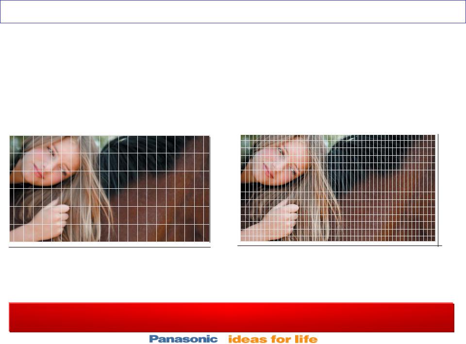
High Resolution (FULL-HD Panel)
The Full-HD plasma panel boasts a total of about 2,070,000 pixels (1920 x 1080).
It renders true-to-life HD images with about twice the resolution of a standard HD panel.
HD PDP |
|
Full-HD PDP |
|
(approx. 1,050,000 pixels) |
|
(approx. 2,070,000 pixels) |
|
|
● |
|
● |
|
|
|
|
768  1080
1080
|
● |
|
●● |
● |
● |
● |
|
1366 |
|
|
1920 |
(Image resolution about twice as high) *When compared to the 50PX600
About Twice the Resolution of a Standard HD PDP!PDP!
9
Difference between the PZ700U & PZ750U.
Only the PZ750U series has:
1.Extra HDMI input (Front) (GH Board)
2.Capability of video Playback (Mpeg2/H.264 on SDHC card ) (JG Board)
3.Pro-Setting & Studio Reference Modes
Movie images are some of the most difficult for TV displays to reproduce.
By working closely with movie studios for many years and applying research by the Panasonic Hollywood Lab, Studio Reference Mode on Panasonic plasma TVs enables the replication of colors that was originally intended by the director, exactly the way they are seen on reference monitors in professional film editing rooms.
Pro-Setting Mode offers the precise, highly detailed adjustment of Image quality to suit personal preferences. Just the touch of a button on the remote executes setting adjustments such as tint, brightness, contour emphasis, gamma compensation and black expansion, which would otherwise require the use of special equipment to accomplish.
The PZ750 models have better skin tones/rendering
10
Board Layout
Board Layout
11

12
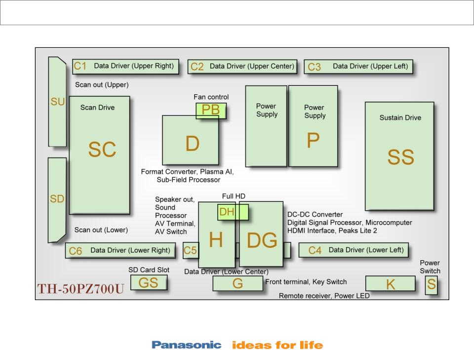
TH-50/58PZ700U Boards Layout & Description
13
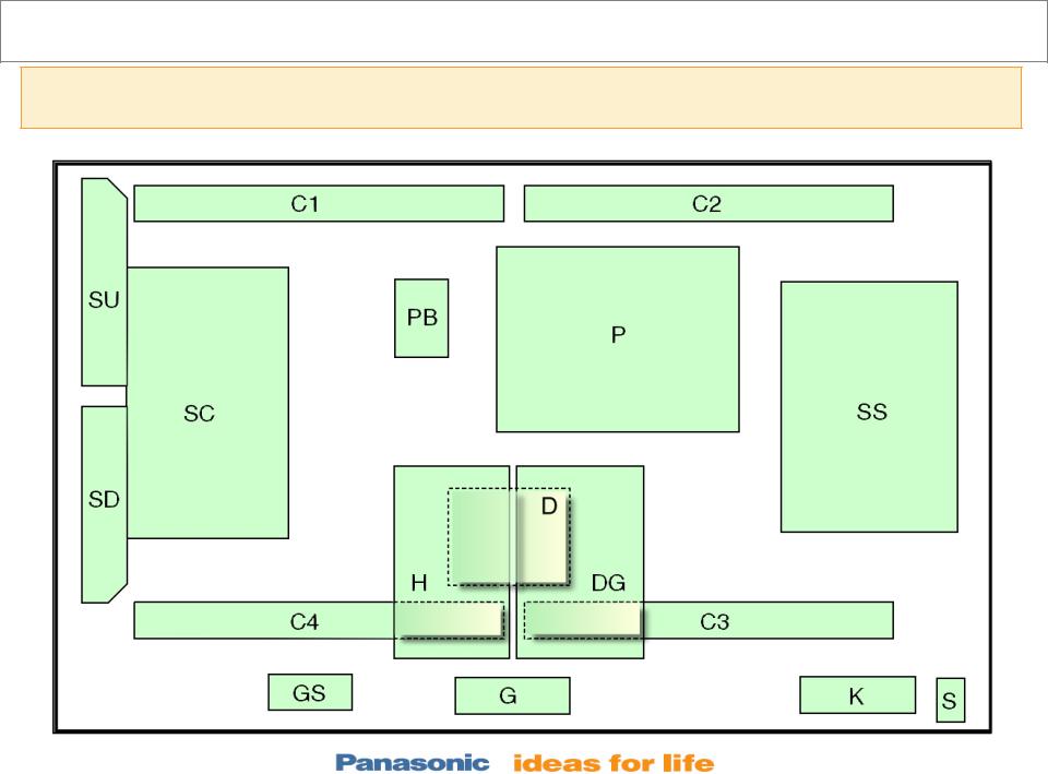
TH-42PZ700U Boards Layout
This is the only model of the PZ700 series that does not have the DH board. The “Full HD” Circuit (DH Board) found on the TH-58/50PZ700U models, is built-into the “DG” Board
14
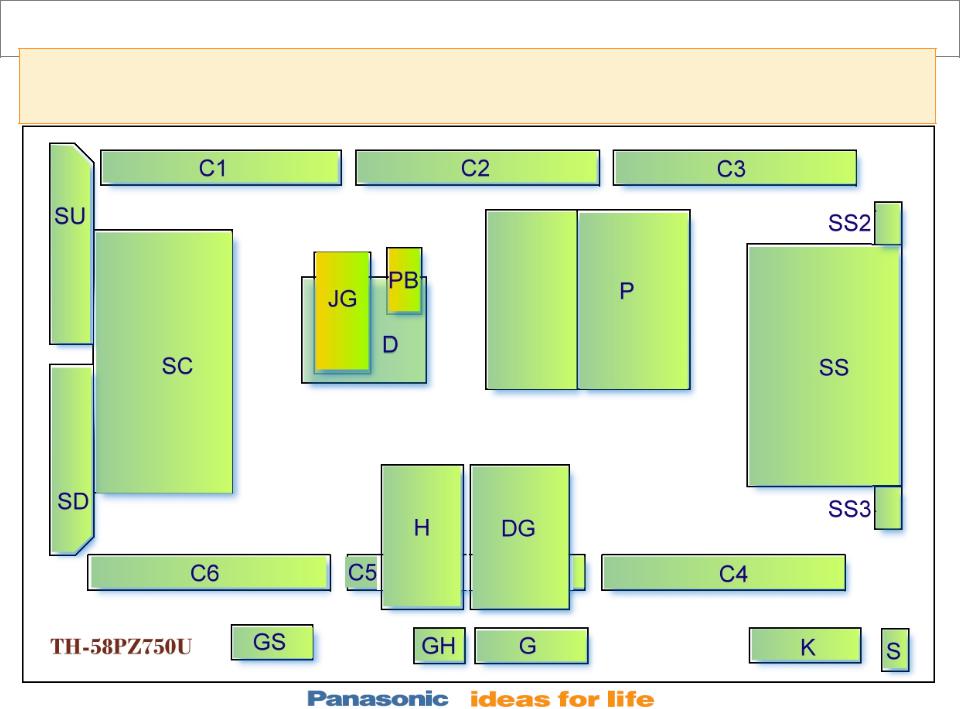
TH-50/58PZ750U Boards Layout
The PZ750 models do not have the DH board. The “Full HD” Circuit (DH Board) found on the TH-58/50PZ700U models, is built-into the “DG” Board
15

•The PZ750 models have a board that processes the video data from the SD card, H.264 Decoder board (JG).
•This board is only used on the PZ750 series.
16
Boards Name
Board Name |
Function |
Board Name |
|
Function |
|
|
|
||||
P |
Power Supply |
D |
Format Converter, Plasma AI, Sub-Field |
|
|
Processor |
|
||||
|
|
|
|
||
PB |
Fan control |
C1 |
|
Data Driver (Upper Right) |
|
H |
Speaker out, Sound Processor AV Terminal, |
C2 |
|
Data Driver (Upper Center) |
|
|
AV Switch |
|
|
|
|
|
C3 |
Data Driver (Upper Left) |
|
||
|
|
|
|||
DG |
DC-DC Converter Digital Signal Processor, |
C4 |
Data Driver (Lower Left) |
|
|
|
Microcomputer HDMI Interface, Peaks Lite 2, |
|
|
|
|
|
C5 |
|
Data Driver (Lower Center) |
|
|
|
Full HD |
|
|
||
|
C6 |
|
Data Driver (Lower Right) |
|
|
|
|
|
|
||
JG |
H264 Decoder (SD Card Video) (PZ750 Only) |
SC |
Scan Drive |
|
|
G |
Front terminal, AV3, Key Switch |
SU |
Scan out (Upper) |
|
|
K |
Remote receiver, Power LED |
SD |
|
Scan out (Lower) |
|
S |
Power Switch |
SS |
|
Sustain Drive |
|
GS |
SD Card Slot |
SS2 |
Sustain Connector (Upper) |
|
|
GH |
HDMI3 in (PZ750 Only) |
SS3 |
Sustain Connector (Lower) |
|
|
DH |
Full HD (TH-50/58PZ700U Only) |
|
|
|
|
17

TH-58PZ750 Boards (Pictorial)
18
Power Supply
Power Supply
19

20
Power Supply
Power Supply
(STAND-BY)
The Power Supply circuit board used on the TH50PZ/PE700U/750U and TH58PZ/PE700U/750U models is divided into 2 different sections: Multi and Vsus
1.The Multi section generates all the Standby voltages plus the F_STB_15V, P15V, P5V, and Vda.
2.The Vsus section generates the Sustain voltage
21

Power Supply (Standby)
22

•When the TV is connected to the AC line, the power supply outputs 5V.
•The 5V is applied to the D board and the DG board. The 5V on the D board in the Panel Drive Section is not used at this time.
•When the DG board receives the 5V from the Power supply, it outputs the “F_STB_ON” command for 30 seconds.
•“F_STB_ON” command is applied to the power supply board to generate the “F_STB15V”, which is applied to the H board.
•The H board has a DC-DC converter circuit that generates the 9V and 5V used by the H, DG, JG, PB, K, and GH.
23
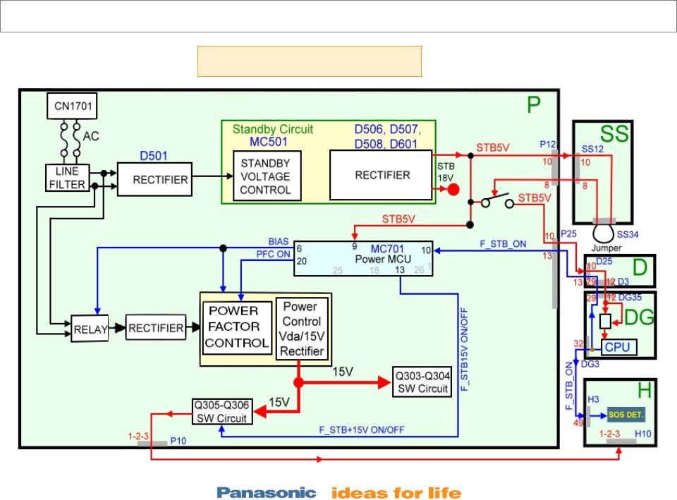
Standby (TH-58PZ750U)
Multi-Section
24

•When AC is applied to the TV, the Standby circuit on the multi-section board outputs 5Vdc.
•The STB5V is applied to the Power MCU (MC701) and a switching transistor of the power supply circuit.
•The STB5V is also provided to the SS board. A jumper at connector SS34 of the SS board routes the 5V back into the power supply board to turn on the switching transistor. When this transistor is on, the STB5V is output to the D and DG boards.
•On the D board, the STB5V is applied to a 3.3V regulator (IC9011). During standby operation, this regulator is kept off to disable the panel drive circuits. The STB5V is also applied to a 3.3V regulator (IC5604) on the DG board to provide the supply voltage (STB3.3V) to the Main CPU (IC1100). The STB3.3V is also applied to the Remote Control receiver and the power LED on the K board. Furthermore, the STB3.3V is provided to the SD card slot (Not shown in the diagram).
25

•When the Main CPU IC1100 receives the 3.3V, it outputs the “TV_SUB_ON/TUNER_SUB_ON” command to the Power MCU (MC701) located on the Power Supply board. Subsequently, the power MCU outputs the following commands:
1.“BIAS ON” to activate the AC relays
2.The “PFC ON” to start the Power Factor Control operation and create the DC voltage needed by the Power Control circuit
3.“F_STB_ON/OFF_” to command the turn-on of the DC-DC converter (Q305-Q306) and output the “F+15V”
The “F+15V” is applied to the 5V/9V regulator, IC3500, on the H board. The output voltages of IC3500 are used on the H and many other circuit boards. To avoid catastrophic failures, they are monitored by an SOS Detect circuit for over-voltage and over-current conditions. The SOS Detect circuit is controlled by the “TUNER_SUB_ON” command from the Main CPU (IC1100) on the DG board.
26
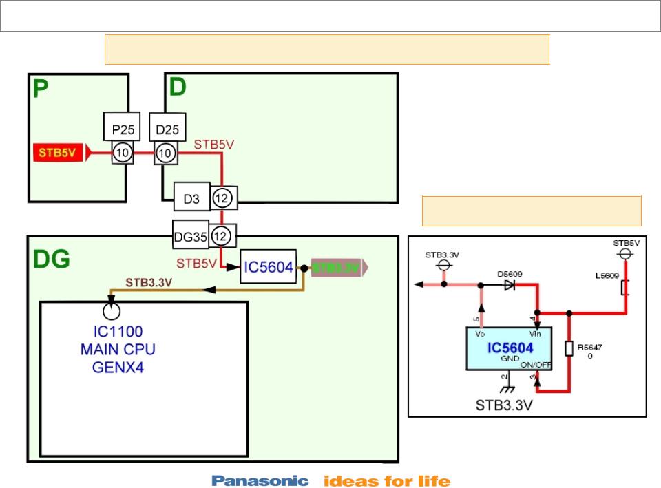
Standby (Main CPU VCC Supply)
STB3.3V provided to the “DG” board during standby
IC5604 (STB3.3V Reg.)
27

•The STB5V is connected to the D and DG boards. During standby, this voltage is not used by the D board. On the A board, the STB5V is applied to the 3.3V regulator (IC5604) to generate the “STB3.3V”, which powers the “MAIN MICON Genx4” (IC1100). The “STB3.3V” is also connected to the K board to power the remote control receiver and the power LED (Not shown here).
28
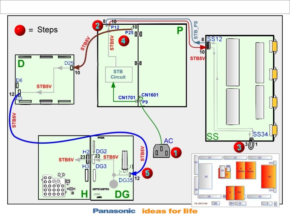
Standby (STB5V Actual Path )
29

•This is the layout of the actual location of the boards and the connectors involved in the development of the STB5V.
•The steps 1~5 indicate the sequence of events that takes place after the TV is plugged-in.
30
 Loading...