

Panasonic SC-VK750, SC-VK850, SC-VK950 User Manual
SC-VK950
Operating Instructions
DVD Stereo System
Model No. SC-VK950
SC-VK850
SC-VK750
SC-VK950 is used in the illustrations unless otherwise
indicated.
Before connecting, operating or adjusting this product,
please read these instructions completely.
Please keep this manual for future reference.
Region number
The region number of this player is “2”.
The player plays DVD-Video marked with labels
containing “2” or “ALL”.
Example:
Table of contents
Accessories .........................................................................3
Safety precautions ..............................................................3
Tray/disc handling procedure ............................................4
The remote control .............................................................4
Simple setup
STEP 1 Positioning and connecting the speakers .........5
STEP 2 Connecting a television, the antennas and the
AC power supply cord .........................................8
STEP 3 QUICK SETUP ....................................................10
STEP 4 Setting the time ..................................................10
DEMO function .................................................................10
Disc information ................................................................11
Discs — Basic play ........................................................... 12
Discs — Convenient functions ........................................ 14
Discs — Using navigation menus ...................................15
Discs — Using On-screen menus ...................................18
Discs — Changing the player’s settings ........................21
The radio ............................................................................23
Cassette tapes — Play and Recording ...........................24
Enjoying karaoke ..............................................................26
Sound field and sound quality .........................................28
Convenient functions
The play/record timer/Sleep timer/Auto-off function/
Dimming the display/Muting the volume/Sound range
display ............................................................................30
Using other equipment ..................................................... 31
Glossary .............................................................................32
About DivX VOD content / Language code list .............. 33
Troubleshooting guide ..................................................... 34
Maintenance ......................................................................36
Specifications ....................................................................37
Control Guide
Main unit ...........................................................................39
Remote control .................................................................40
RQTV0148-2G
GSGC
En
H0506VT2076
Dear customer
VK750
VK850
VK950
V
I
D
E
O
O
U
T
S
V
I
D
E
O
O
U
T
C
O
M
P
O
N
E
N
T
V
I
D
E
O
O
U
T
Y
P
R
P
B
L
I
N
E
O
U
T
Thank you for purchasing this product.
ENGLISH
For optimum performance and safety, please read these
instructions carefully.
: indicates features applicable to SC-VK950 only
: SC-VK850 only
: SC-VK750 only
System SC-VK950 SC-VK850 SC-VK750
Main unit SA-VK950 (1 unit) SA-VK850 (1 unit) SA-VK750 (1 unit)
Front speakers SB-VK950 (2 units) SB-VK850 (2 units) SB-VK750 (2 units)
Center speaker SB-PC950 (1 unit) SB-PC850 (1 unit) SB-PC750 (1 unit)
Surround speakers SB-PS950 (2 units) SB-PS850 (2 units) SB-PS750 (2 units)
Subwoofer(s) SB-WVK950 (2 units) SB-WVK850 (1 unit) ----
CAUTION!
•
DO NOT INSTALL OR PLACE THIS UNIT IN A
BOOKCASE, BUILT-IN CABINET OR IN ANOTHER
CONFINED SPACE. ENSURE THE UNIT IS WELL
VENTILATED. TO PREVENT RISK OF ELECTRIC SHOCK
OR FIRE HAZARD DUE TO OVERHEATING, ENSURE
THAT CURTAINS AND ANY OTHER MATERIALS DO NOT
OBSTRUCT THE VENTILATION VENTS.
• DO NOT OBSTRUCT THE UNIT’S VENTILATION
OPENINGS WITH NEWSPAPERS, TABLECLOTHS,
CURTAINS, AND SIMILAR ITEMS.
• DO NOT PLACE SOURCES OF NAKED FLAMES, SUCH
AS LIGHTED CANDLES, ON THE UNIT.
• DISPOSE OF BATTERIES IN AN ENVIRONMENTALLY
FRIENDLY MANNER.
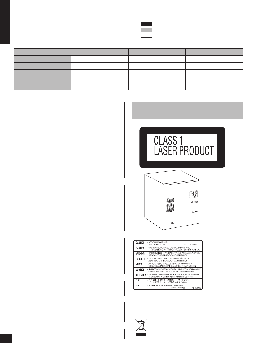
CAUTION!
THIS PRODUCT UTILIZES A LASER.
USE OF CONTROLS OR ADJUSTMENTS OR
PERFORMANCE OF PROCEDURES OTHER THAN
THOSE SPECIFIED HEREIN MAY RESULT IN
HAZARDOUS RADIATION EXPOSURE.
DO NOT OPEN COVERS AND DO NOT REPAIR
YOURSELF. REFER SERVICING TO QUALIFIED
PERSONNEL.
WARNING:
TO REDUCE THE RISK OF FIRE, ELECTRIC SHOCK
OR PRODUCT DAMAGE, DO NOT EXPOSE THIS
APPARATUS TO RAIN, MOISTURE, DRIPPING OR
SPLASHING AND THAT NO OBJECTS FILLED WITH
LIQUIDS, SUCH AS VASES, SHALL BE PLACED ON THE
APPARATUS.
Operations in these instructions are described mainly for
the remote control, but you can do the operations on the
main unit if the controls are the same
(Inside of product)
2
The socket outlet shall be installed near the equipment and
easily accessible or the mains plug or an appliance coupler
shall remain readily operable.
This product may rece ive ra dio interfe rence cause d by
mo bi le tel ephones during u se. If suc h i nterf er ence i s
apparent, please increase separation between the product
and the mobile telephone.
RQTV0148
THI S U N IT IS I N TEND E D FOR U S E IN TR OPI C A L
CLIMATES.
2
- If you see this symbol-
Information on Disposal in other Countries outside the
European Union
This symbol is only valid in the European Union.
If you wish to discard this product, please contact
your local authorities or dealer and ask for the
correct method of disposal.
Fuse cover
Fuse
(5 ampere)
Fuse
(5 ampere)
VK950
VK850
VK750
Accessories
Please check and identify the supplied accessories.
1 Remote control [➡ page 4]
(EUR7662YH0)
(EUR7662YF0)
AC power supply cord [➡ page 8]
For all areas
1 Video cable [➡ page 8]
1 AM loop antenna [➡ page 8]
1 FM indoor antenna [➡ page 8]
2 Batteries [➡ page 4]
The included AC power supply cord is for use with this unit
•
only. Do not use it with other equipment.
Do not use an AC power supply cord from other equipment.
•
For Saudi Arabia and Kuwait
CAUTION:
The AC voltage is different according to the area.
Be sure to set the proper voltage in your area before use.
(For details, please refer to page 9.)
For Saudi Arabia and Kuwait
Note on AC power supply cord
Before use
Remove the connector cover.
How to replace the fuse
The location of the fuse differ according to the type of AC
power supply cord (figure A and B). Confirm the AC power
supply cord fitted and follow the instructions below.
Illustrations may differ from actual AC power supply cord.
For Saudi Arabia and Kuwait
Safety precautions
Placement
Set the unit up on an even surface away from direct sunlight,
high temperature, high humidity, and excessive vibration. These
conditions can damage the cabinet and other components,
thereby shortening the unit’s service life.
Do not place heavy items on the unit.
Voltage
Do not use high voltage power sources. This can overload
the unit and cause a fire.
Do not use a DC power source. Check the source carefully
when setting the unit up on a ship or other place where DC is
used.
AC power supply cord protection
Ensure the AC power cord is connected correctly and not
damaged. Poor connection and lead damage can cause fire or
electric shock. Do not pull, bend, or place heavy items on the
lead.
Grasp the plug firmly when unplugging the lead. Pulling the
AC power cord can cause electric shock.
Do not handle the plug with wet hands. This can cause
electric shock.
Foreign matter
Do not let metal objects fall inside the unit. This can cause
electric shock or malfunction.
Do not let liquids get into the unit. This can cause electric
shock or malfunction. If this occurs, immediately disconnect the
unit from the power supply and contact your dealer.
Do not spray insecticides onto or into the unit. They contain
flammable gases which can ignite if sprayed into the unit.
Service
Do not attempt to repair this unit by yourself. If sound is
interrupted, indicators fail to li ght, smoke appears, or any
other problem that is not covered in these instructions occurs,
disconnect the AC power cord and contact your dealer or an
authorized service center. Electric shock or damage to the unit
can occur if the unit is repaired, disassembled or reconstructed
by unqualified persons.
Extend operating life by disconnecting the unit from the power
source if it is not to be used for a long time.
ENGLISH
Accessories / Safety precautions
1. Open the fuse cover with a screwdriver.
2. Replace the fuse and close or attach the fuse cover.
RQTV0148
3
3
Tray/disc handling procedure
1
SINGLE CHANGE
MULTI CHANGE
OPEN/CLOSE
2
3
4
5
MIC VO
L
MIC 1
MIC
2
OPEN
SUBWOOFER
SOUND EQ
SUPER SOUND EQ
SUPER SURROUND
SURROUND
ENHANCER
PHONES
MUSIC POR
T
OPEN
AC
IN
V
O
L
U
M
E
TAPE DVD/CDTUNERMUSIC PORT
DEMO
RECORDDECK 1/2DISPLAY STOPREW/ /FF
OPEN/CLOSE
1
SINGLE CHANGE
MULTI CHANGE
OPEN/CLOSE
2
3
4
5
MIC VO
L
MIC
1
MIC
2
OPEN
SUBWOOFER
SOUND EQ
SUPER SOUND EQ
SUPER SURROUND
SURROUND
ENHANCER
PHONES
MUSIC POR
T
OPEN
AC
IN
V
O
L
U
M
E
TAPE DVD/CDTUNERMUSIC PORT
DEMO
RECORDDECK 1/2DISPLAY STOPREW/ /FF
Adhere to the following to avoid problems.
ENGLISH
Removing the power plug
Press [^] to turn off the unit and remove the power plug only after all the displays have disappeared.•
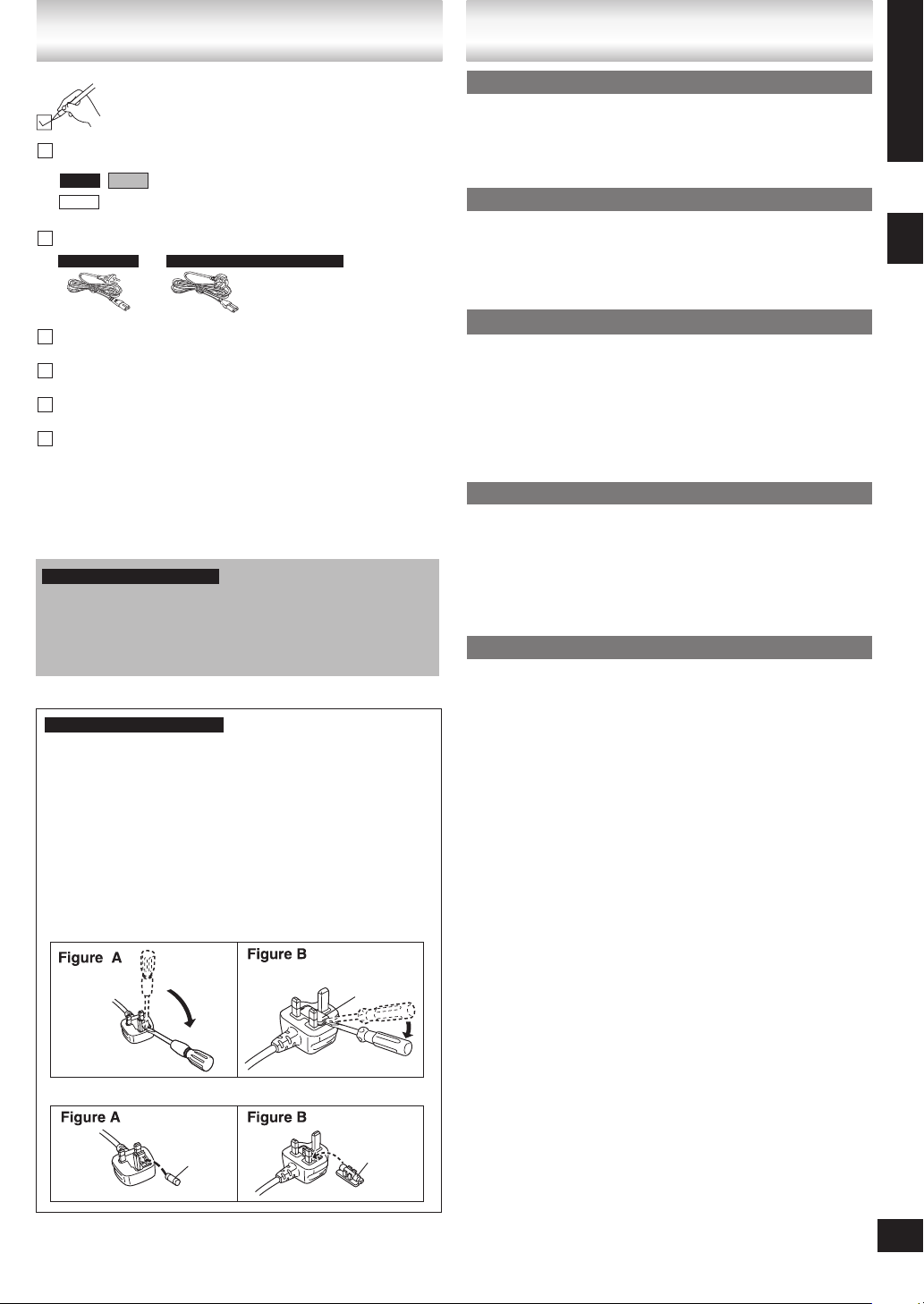
Tray caution
Always press [;, OPEN/CLOSE] to insert or remove a disc.
•
Do not push or pull out the tray by hand as this will cause an
•
accident.
Disc handling precautions
Do not attach labels or stickers to discs (This may cause disc
•
warping, rendering it unusable).
Do not write on the label side with a ball-point pen or other
•
hard writing instrument.
Tray/disc handling procedure / The remote control
Do not use record cleaning sprays, benzine, thinner, static
•
electricity prevention liquids or any other solvent.
Do not use scratch-proof protectors or covers.
•
Do not use the following discs:
•
Discs with exposed adhesive from removed stickers or
–
labels (rented discs, etc).
Discs that are badly warped or cracked.
–
Irregularly shaped discs, such as heart shapes.
–
Inserting a disc
Place the disc label up in the center of the tray.
•
Insert only one disc into each tray.
•
Cleaning discs
DVD-V VCD CD
Wipe with a damp cloth and then wipe dry.
and other recordable formats
DVD-VR
Clean with an optional DVD-RAM/PD disc cleaner (LF-
•
K200DCA1, where available).
Never use cloths or cleaners for CDs, etc.
•
4
RQTV0148
4
The remote control
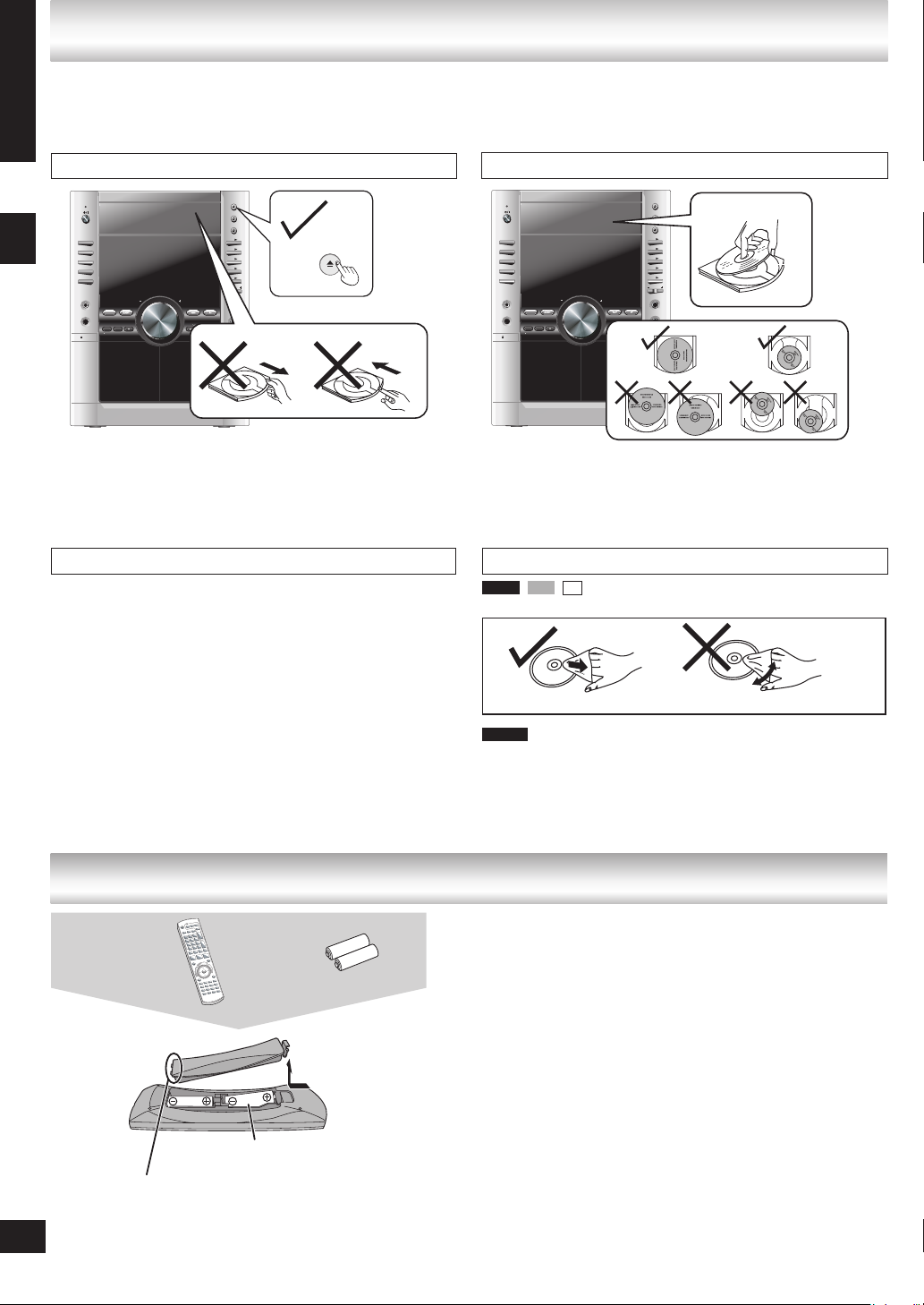
Remote control
Insert this side first
when closing
R6/LR6, AA
Insert so the poles (+ and – )
•
match those in the remote control.
Do not use rechargeable type
•
batteries.
Batteries
Press on the tab to
open
■ Do not:
mix old and new batteries.
•
use different types at the same time.
•
heat or expose to flame.
•
take apart or short circuit.
•
attempt to recharge alkaline or manganese batteries.
•
use batteries if the covering has been peeled off.
•
Mishandling of batteries can cause electrolyte leakage which
can damage items the fluid contacts and may cause a fire.
Remove if the remote control is not going to be used for a long
period of time. Store batteries in a cool, dark place.
■ Use
Aim at the sensor, avoiding obstacles, at a maximum range of
7 m directly in front of the unit.
Simple setup
(S B- PC9 50 /
SB -P C85 0
)
(S B-PS950
/
SB -PS850)
(S B-PS750)
(S B- PC7 50
)
30
o
12 0
o
30
(S B- WVK 95 0)
(S B- WVK 95 0/
SB -W VK8 50 )
(S B-PS950/
SB -PS850
)
(S B-PS750
)
(S B- VK9 50 /
SB -V K85 0
/
SB -V K75 0
)
(S B- VK9 50 /
SB -V K85 0/
SB -V K75 0)
o
VK850
VK950
Cables and equipment are sold separately unless
otherwise indicated.
ENGLISH
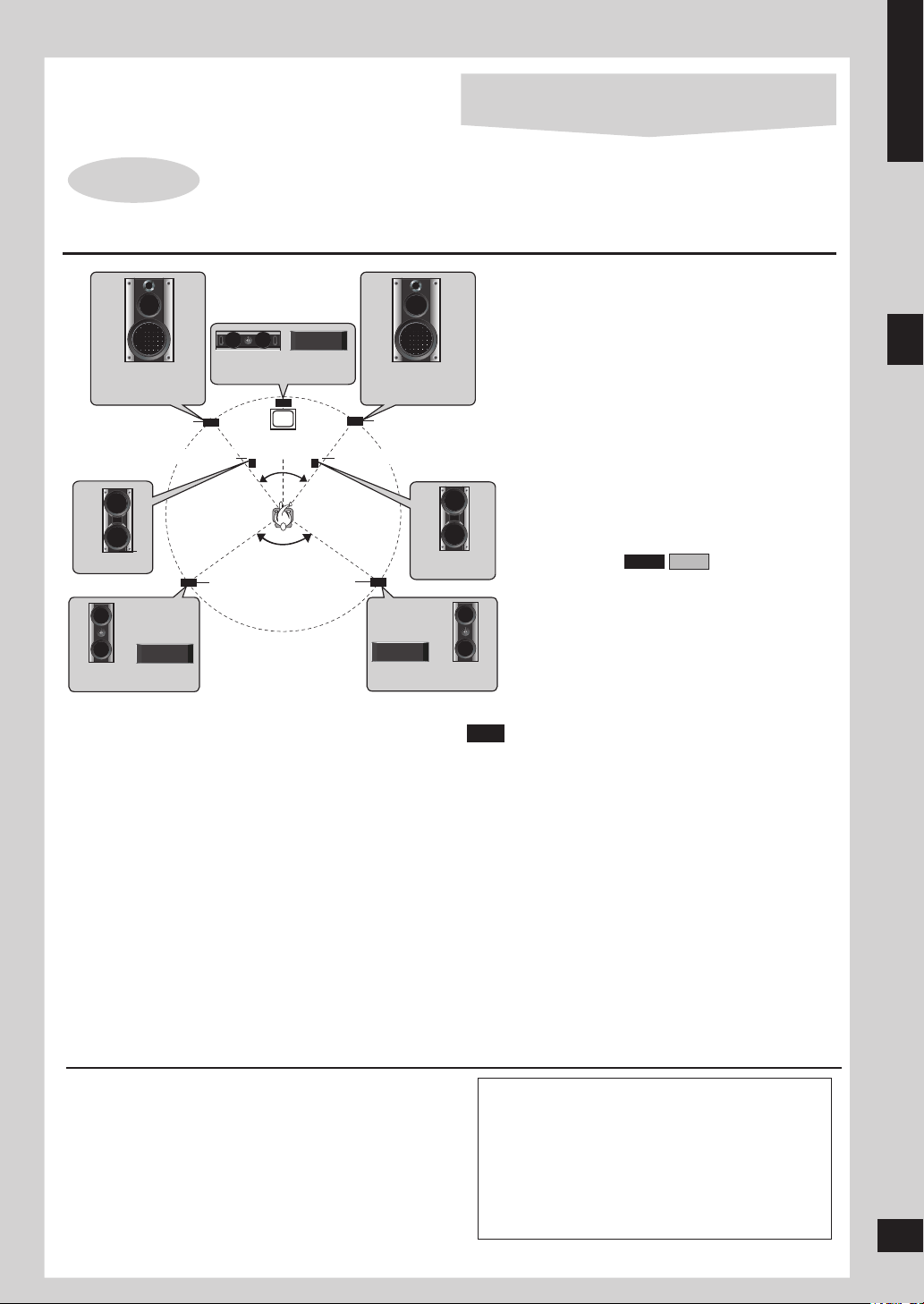
STEP 1
Positioning
Front speaker (left)
Subwoofer (left)
Positioning and connecting the speakers
Place the front, center, and surround speakers
Center speaker
Television
(not included)
Surround
speaker
(left)
Surround
speaker
(right)
Front speaker (right)
Subwoofer (right)
at approximately the same distance from the
seating position.
Front speakers
Speakers are designed identically so that no left
or right channel orientation is necessary.
Center speaker
Do not place the center speaker directly on the
television as vibration may cause it to fall or
disrupt the picture.
Place it on a rack or shelf.
Surround speakers
Place on the side of or slightly behind the seating
area, higher than ear level.
Subwoofer(s)
Place on either side of the television, on the floor
or a sturdy shelf to reduce vibration.
Leave 10 cm at the rear for ventilation.
Simple setup
Positioning for best effect
How you set up your speakers can affect the bass and the
sound field. Note the following points.
Place speakers on flat secure bases.
•
Placing speakers too close to floors, walls, and corners
•
can result in excessive bass. Cover walls and windows
with a thick curtain.
Keep your speakers at least 10 mm away from the
•
system for proper ventilation.
The angles in the diagrams are approximate.
•
Use only the supplied speakers
Using other speakers can damage the unit and sound
•
quality will be negatively affected.
Set the speakers up on an even surface to prevent them
•
from falling. Take proper precautions to prevent the
speakers from falling if you cannot set them up on an
even surface.
If irregular coloring occurs on your television
The supplied speakers are designed to be used close to
a television, but the picture may be affected with some
televisions and setup combinations.
If this occurs, turn the television off for about 30 minutes.
The television’s demagnetizing function should correct the
problem.
If it persists, move the speakers further away from the
television.
Note
You can damage your speakers and shorten their
•
Step 1: Positioning and connecting the speakers
useful life if you play sound at high levels over extended
periods.
Reduce the volume in the following cases to avoid
•
damage.
When playing distorted sound.
–
When the speakers emit strange noises (howling)
–
from a record player, noise from FM broadcasts, or
continuous signals from an oscillator, test disc, or
electronic instrument.
When adjusting the sound quality.
–
When turning the unit on or off.
–
Caution
Use the speakers only with the recommended
•
system. Failure to do so can damage the main
unit and speakers, and can cause fire. Consult
a qualified service person if damage occurs or
if a sudden change in performance is apparent.
Do not attempt to attach these speakers to walls
•
using methods other than those described in
RQTV0148
this manual.
5
5
ENGLISH
L
R
L
R
L
R
L
R
+
-
VIDEO
OU
T
S VIDEO
OU
T
COMPONENT
VIDEO OU
T
Y
P
R
P
B
LINE
OU
T
VIDEO
OUT
S VIDEO
OU
T
COMPONENT
VIDEO OUT
Y
P
R
P
B
R
L
VOLT ADJ
LINE
OU
T
R
L
R
L
R
L
VIDEO
OU
T
S VIDEO
OU
T
FM ANT AM ANT
COMPONENT
VIDEO OU
T
Y
P
R
P
B
L
R
LINE
OU
T
L
R
+
-
SPEAKERS
R
L
VOLT ADJ
R
L
+
-
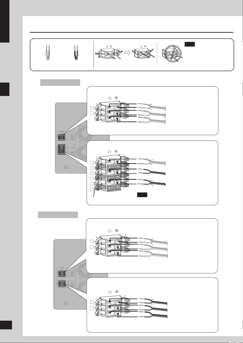
Connecting
Gray (+)
Blue (–)
VK950
Black (–)
Red (+)
Connect so cord colors match the terminal colors.
Connecting center and surround speakers
Note
Never short-circuit positive
•
(+) and negative (–)
speaker wires.
Incorrect connection can
damage the speakers.
Simple setup
Step 1: Positioning and connecting the speakers
VK850
6
6
RQTV0148
Blue
Gray
Blue (–)
Gray (+)
Connecting front speakers and subwoofers
Blue
Gray
Red
Red
Blue (–)
Gray (+)
Black (–)
Red (+)
Note
Black
Connect the right (R) side in the same way.
Connecting center and surround speakers
Blue
Gray
Blue (–)
Gray (+)
Connecting front speakers and subwoofers
Black
Red
Black (–)
Red (+)
Surround speaker (left)
Surround speaker (right)
Center speaker
Front speaker (left)
(High frequency)
Front speaker (left)
(Low frequency)
Subwoofer (left)
Surround speaker (left)
Surround speaker (right)
Center speaker
Front speaker (left)
Front speaker (right)
Subwoofer
VIDEO
OU
T
SVIDEO
OU
T
FMANT AMANT
VOLTAD
J
EX LOOP
COMPONENT
VIDEOOUT
Y
P
R
P
B
75
Ω
L
R
LINE
OU
T
L
R
LINE
OU
T
S.WOOFER
OU
T
R
L
R
L
+
-
+
-
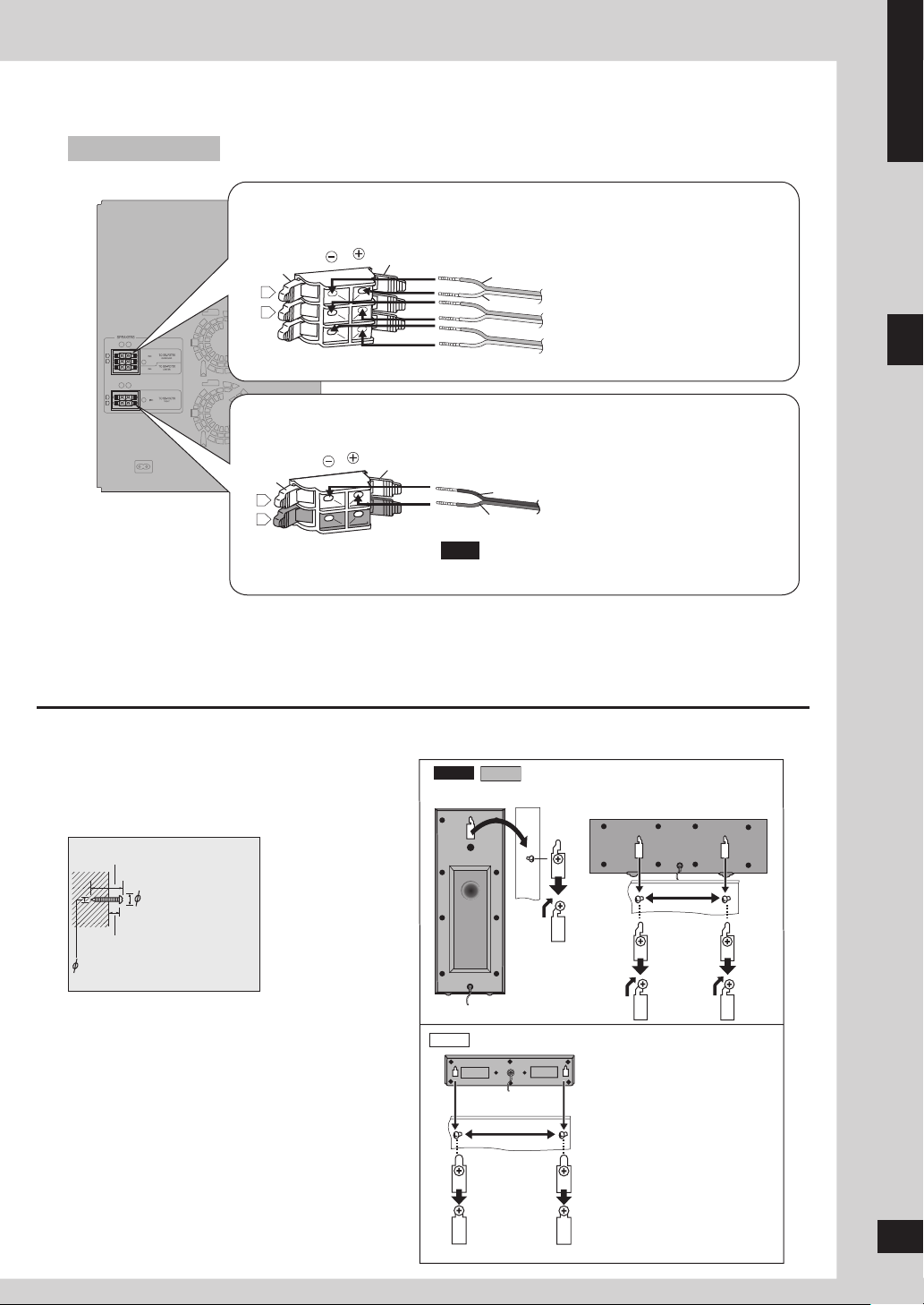
VK750
VK950
VK850
VK750
ENGLISH
Connecting center and surround speakers
Blue
Gray
Blue (–)
Gray (+)
Connecting front speakers
Black
Red
Black (–)
Red (+)
Note
Connect the right (R) side in the same way.
Other speaker setup options – attaching to a wall
You can attach the surround and center speakers to a wall.
Surround speaker (left)
Surround speaker (right)
Center speaker
Simple setup
Front speaker (left)
Step 1: Positioning and connecting the speakers
1 Drive a screw (not included) into the wall.
30 - 35 mm
7.5 - 9.4 mm
7 - 9 mm
3.0 - 4.0 mm
2 Fit the hole securely onto the screw(s).
The wall or pillar on which the speakers are to be
attached should be capable of supporting 10 kg per
screw. Consult a qualified building contractor when
attaching the speakers to a wall. Improper attachment
may result in damage to the wall and speakers.
Surround speaker
Center and Surround speakers
200 mm
Center speaker
190 mm
RQTV0148
7
7
ENGLISH
VIDEO IN
REC
OUT
TO SB-PS950
SURROUND
TO SB-VK950
FRONT
TO SB-WVK950
SUBWOOFER
(4Ω)
(4
Ω)
HIGH
(4
Ω)
(4
Ω)
LO
W
(8
Ω)
TO SB-PS950
CENTER
L
R
R
L
R
L
R
L
R
+ -
L
R
VIDEO
OUT
COMPONENT
VIDEO OU
T
Y
FM ANT
(75
)
VOLT ADJ
110-127V 220-240V
P
R
P
B
COMPONENT
VIDEO IN
S-VIDEO
IN
AM ANT
EXT
LOOP ANT
GROUND
FM ANT
(75
Ω)
LOOP
S VIDEO
OU
T
AC IN
AC IN
3
LOOP ANT
GROUND
2
1
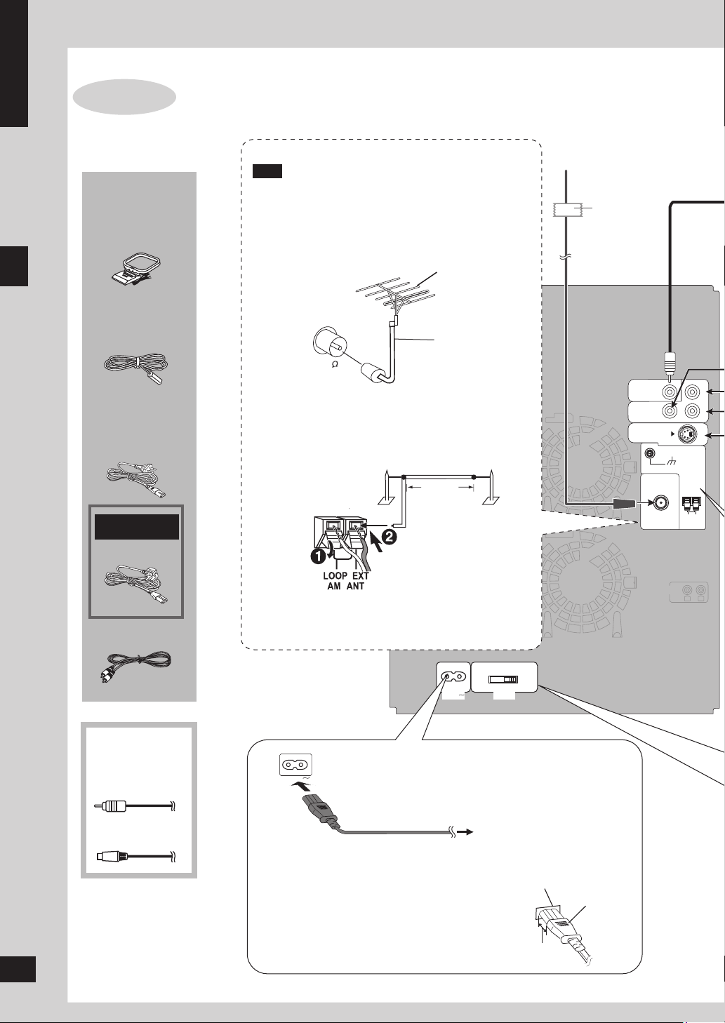
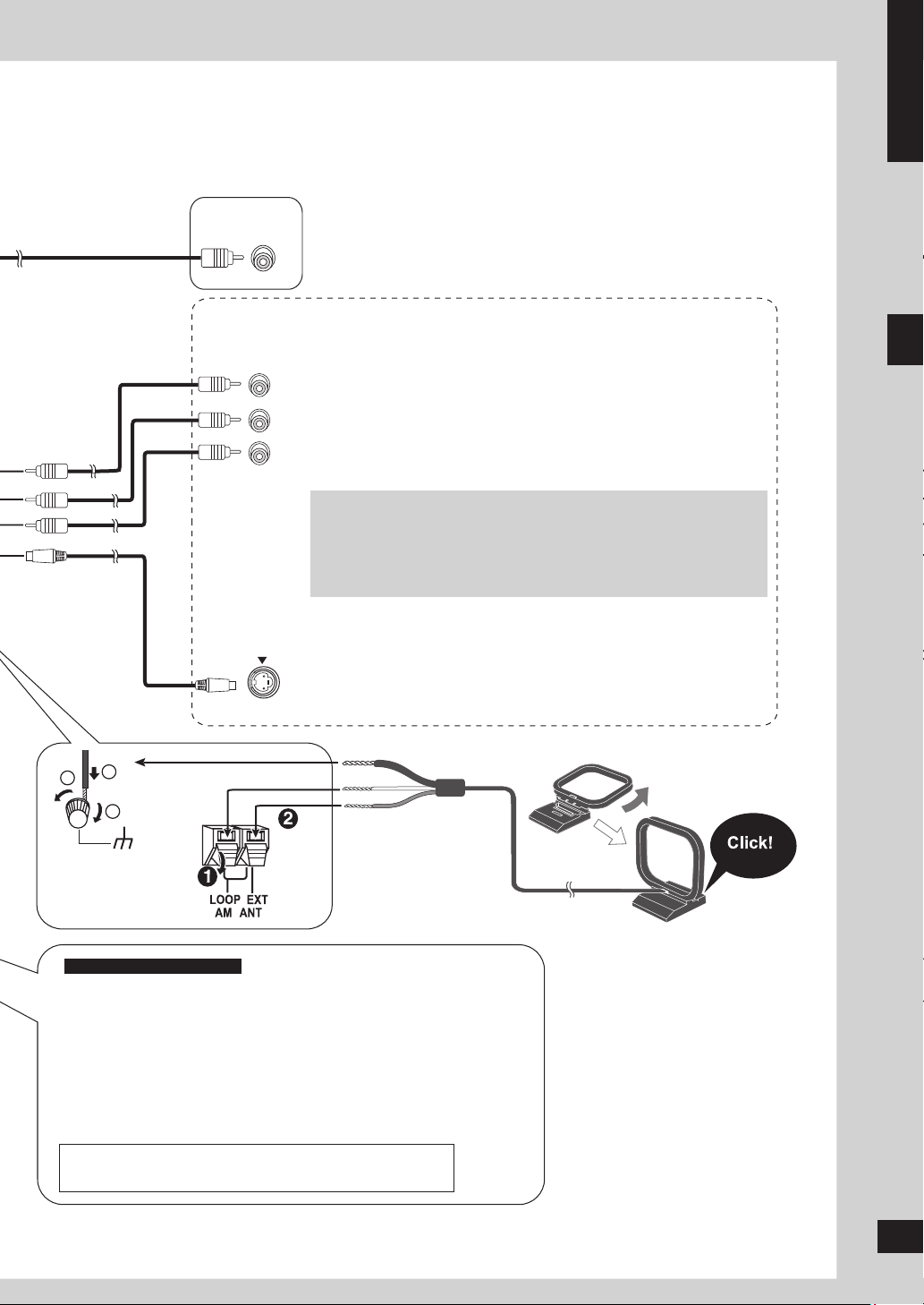
STEP 2
Connecting a television, the antennas and the AC
power supply cord
Simple setup
Supplied
accessories
AM loop
antenna
FM indoor
antenna
AC power
supply cord
For Saudi Arabia
and Kuwait
or
Video cable
Use outdoor antennas if radio reception is poor.
Note
Disconnect the outdoor antenna when the unit is not
in use.
Do not use the outdoor antenna during a lightning
storm.
FM indoor antenna
Fix the other end of the
antenna where reception
is best.
Adhesive
tape
■ FM outdoor antenna (using a television antenna)
FM outdoor antenna
75 Ω coaxial
cable
Disconnect the FM indoor antenna.
•
The antenna should be installed by a competent
•
technician.
■ AM outdoor antenna
Run a piece of vinyl wire horizontally across a
•
AM outdoor antenna
5-12m
Connect the AM
loop antenna
window or other convenient location.
Leave the loop antenna connected.
•
Other accessories
Step 2 : Connecting a television, the antennas and the AC power supply cord
(not included)
Component
video cable
Connect the AC power supply cord after all other
connections are complete.
AC power supply cord
S video cable
Insertion of connector
Even when the connector is perfectly inserted,
depending on the type of inlet used, the front
part of the connector may jut out as shown in the
drawing. However there is no problem using the
RQTV0148
unit.
8
8
To household AC socket
Appliance inlet
Connector
Approx. 3.5 mm
VIDEO IN
Y
P
R
PB
COMPONENT
VIDEO IN
S-VIDEO
IN
3
LOOP ANT
GROUND
2
1
Conserving power
The unit consumes a small amount of power (approx. 0.9 W) even when it is turned off with [^]. To save power
when the unit is not to be used for a long time, unplug it from the household AC socket. You will need to reset
some memory items after plugging in the unit.
ENGLISH
Video cable
Component
video cable
S video cable
Television
Television
Television
■ Connecting a television with a VIDEO IN terminal
VIDEO OUT terminal
Do not connect the unit through a video cassette recorder, because the
picture may not be displayed correctly due to copy guard protection.
■ Connecting a television with COMPONENT VIDEO IN terminals
COMPONENT VIDEO OUT terminals
These terminals can be used for either interlace or progressive
output and provide a purer picture than the S VIDEO OUT terminal.
Connection using these terminals outputs the color difference signals
(PB/PR) and luminance signal (Y) separately in order to achieve high
fidelity in reproducing colors. The description of the component video
input terminals depends on the television or monitor (e.g. Y/PB/PR,Y/BY/R-Y, Y/CB/CR). Connect to terminals of the same color.
To enjoy progressive video
1. Connect to the component video input terminals on a 480p or
576p compatible television. (Video will not be displayed correctly if
connected to an incompatible television.)
2. Select “480p” or “576p” for Video Output Mode (Picture Menu, ➡
page 19).
■ Connecting a television with an S VIDEO IN terminal
S VIDEO OUT terminal
The S VIDEO terminal achieves a more vivid picture than the VIDEO
OUT terminal by separating the chrominance (C) and luminance (Y)
signals. (Actual results depend on the television.)
Simple setup
Black
For Saudi Arabia and Kuwait
White
Red
Before connecting the AC power supply cord, set the
voltage.
Voltage Selector
Use a flat-head screwdriver to set the voltage selector on the rear panel
to the appropriate position for the area in which this system is used.
AC power supply cord
Use 3-pin AC power supply cord for 220 to 240 V.
•
Use 2-pin AC power supply cord for 110 to 127 V.
•
BE SURE TO READ THE NOTE ON AC POWER SUPPLY
CORD ON PAGE 3 BEFORE CONNECTION.
AM loop antenna
Stand the antenna up on its
base.
Keep loose antenna cord
away from other wires and
cords.
Step 2 : Connecting a television, the antennas and the AC power supply cord
RQTV0148
9
9
ENGLISH
1
SINGLE CHANGE
MULTI CHANG
E
OPEN/CLOSE
2
3
4
5
MIC VO
L
MIC
1
MIC
2
OPEN
SUBWOOFER
SOUND EQ
SUPPER SOUND EQ
SUPER SURROUND
SURROUND
ENHANCER
PHONES
MUSIC PORT
OPEN
AC
IN
AUTO REVERSE PLAYBACK /RECORDRECORDAUTO REVERSE PLAYBACK
V
O
L
U
M
E
TAPE DVD/CDTUNERMUSIC PORT
DEMO
RECORDDECK 1/2DISPLAY STOPREW/ /FF
2 3 1
2
3
4 5
6
1
DISPLAY
-DEMO
CLOCK/
TIMER
u, i,
2/REW,
FF/1
Simple setup
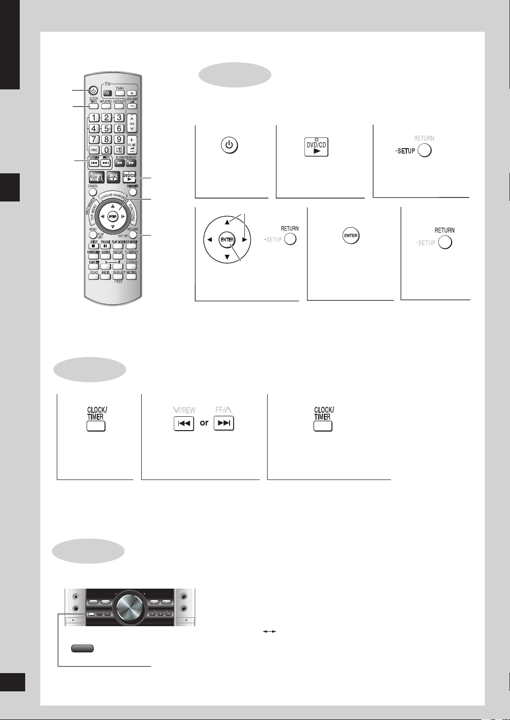
STEP 3
^
Turn on the television and select the appropriate video input on the television
QUICK SETUP
to suit the connection for the unit.
Press and hold to
DVD/CD q
Power ON. Select “DVD/CD”.
show the QUICK
SETUP screen.
e, r, w, q,
ENTER
RETURN,
-SETUP
Select
Confirm
Select the option
from the screen.
Press to finish
QUICK SETUP.
Press to exit.
STEP 4
Press to select
“CLOCK”.
Step 3: QUICK SETUP / Step 4: Setting the time / DEMO function
This is a 24-hour clock.
Press [CLOCK/TIMER] when the unit is on to display the time.
•
Reset the clock regularly to maintain accuracy.
•
RQTV0148
DEMO function
Press and hold.
Setting the time
Set the time
(press within 6 seconds or so).
Press [CLOCK/TIMER] to
finish setting the time.
When the unit is first plugged in, a demonstration of its functions may be
shown on the display.
If the demo setting is off, you can see a demonstration by turning on the
demo.
The display changes each time the button is held down.
DEMO ON DEMO OFF
You can reduce the power consumed in standby mode by turning the
demonstration off.
10
10
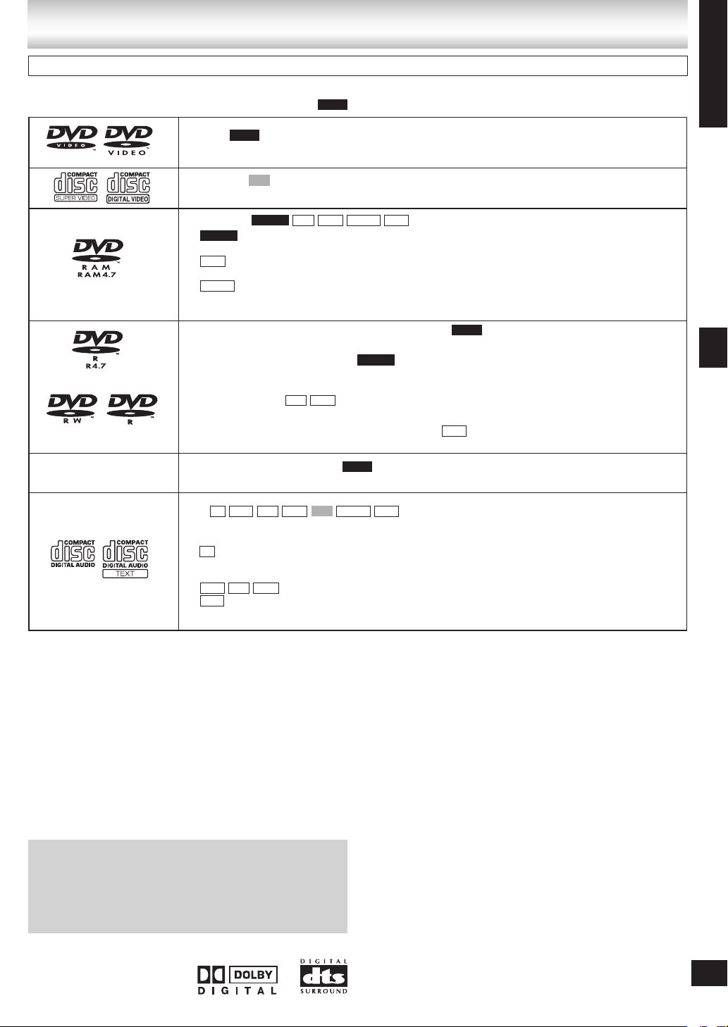
Disc information
Discs that can be played
Operations you can perform depend on the disc format. The following table shows the formats you can use and the
indications used in these operating instructions. (e.g. )
DVD-V
DVD-V
—
Video CD
VCD
Including SVCD (Conforming to IEC62107).•
DVD-RAM
Recorded with devices using Version 1.1 of the Video Recording Format (a unified video
•
DVD-VR
recording standard), such as DVD video recorders, DVD video cameras and personal computers.
Recorded with Panasonic SD multi cameras or DVD video recorders using the DCF
•
JPEG
(Design rule for Camera File system) Standard Version 1.0.
Recorded with the Panasonic SD multi cameras or DVD video recorders (conforming
•
MPEG4
to SD VIDEO specifications (ASF standard)/MPEG (Simple Profile) video system/G.726 audio
system).
DVD-R (DVD-Video)#1 /DVD-RW (DVD-Video)
Discs recorded and finalized#2 on DVD video recorders or DVD video cameras.
•
DVD-R (VR)#1 /DVD-RW (VR)
Discs recorded and finalized#2 on DVD video recorders or DVD video cameras using Version 1.1
•
or 1.2 (DVD-R only) of the Video Recording Format (a unified video recording standard).
DVD-R/DVD-RW
Finalize#2 the disc after recording.
•
R DL
—
DVD-R (DivX Video)/DVD-RW (DivX Video)
Finalize#2 the disc after recording.
•
+R (Video)#1 /+RW (Video)
Discs recorded and finalized#2 on DVD video recorders or DVD video cameras.•
DVD-V
MP3 JPEG
DVD-VR
DVD-V
#3, #4
DivXDVD-VR MP3 JPEG MPEG4
DVD-V
#3, #4
DivX
ENGLISH
Disc information
CD
CD
•
WMA MP3
This unit can play CD-R/RW recorded with the above formats. Close the sessions or finalize#2 the
JPEG VCD MPEG4 DivX
#3, #4
disc after recording.
CD
This unit is compatible with HDCD, but does not support the Peak Extend function (a function
•
which expands the dynamic range of high level signals).
HDCD-encoded CDs are encoded with 20 bits and sound better than CDs encoded with 16 bits.
WMA MP3 JPEG
This unit also plays HighMAT discs.
•
WMA
This unit does not support Multiple Bit Rate (MBR: an encoding process for audio content
•
that produces an audio file encoded at several different bit rates).
#1
Includes single-sided, dual layer discs.
#2
A process that allows play on compatible equipment.
#3
Functions added with DivX Ultra are not supported.
#4
Plays all versions of DivX® video (including DivX®6) with standard playback of DivX® media files. Certified to the DivX Home
Theater Profile. GMC (Global Motion Compensation) is not supported.
It may not be possible to play the above discs in all cases due to the type of disc or condition of the recording.•
g Discs that cannot be played
DVD-RW version 1.0, DVD-Audio, DVD-ROM, CD-ROM, CDV,
CD-G, SACD, Photo CD, DVD-RAM that cannot be removed
from their cartridges, 2.6-GB and 5.2-GB DVD-RAM, and “Chaoji
VCD” available on the market including CVD, DVCD and SVCD
that do not conform to IEC62107.
Playing DVDs and Video CDs
The producer of these discs can control how they are played
so you may not always be able to control play as described in
these operating instructions (for example if the play time is not
displayed or if a Video CD has menus).
Read the disc’s instructions carefully.
■ Note about using a DualDisc
Do not use a DualDisc in this unit as it may not be possible to
•
insert it correctly and it may get scratched or scraped.
The “CD” sides of DualDisc do not meet the CD-DA standard
•
so it may not be possible to play them on this unit.
■ Video systems
This unit can play PAL and NTSC, but your television must
–
match the system used on the disc.
PAL discs cannot be correctly viewed on an NTSC
–
television.
This unit can convert NTSC signals to PAL 60 for viewing on
–
a PAL television (➡ “Video” tab—NTSC Disc Output, page
21).
■ Audio format of DVDs
This unit automatically
•
recognizes and decodes
discs with these symbols.
RQTV0148
11
11
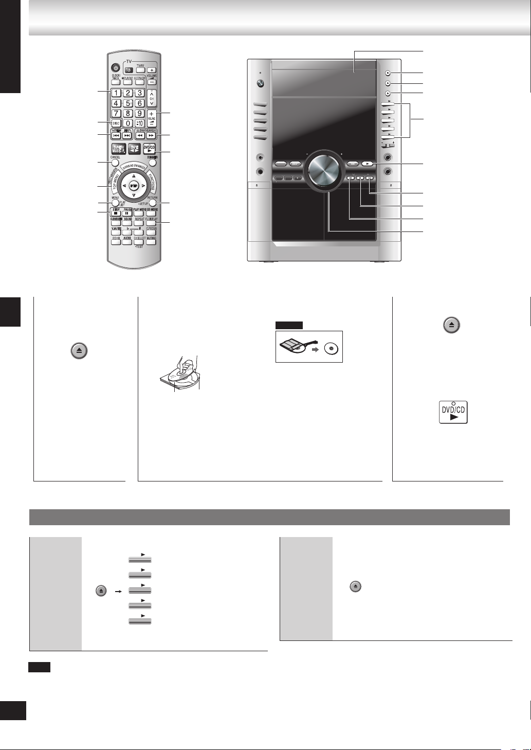
Discs — Basic play
OPEN/CLOSE
1
OPEN/CLOSE
1
SINGLE CHANGE
MULTI CHANGE
OPEN/CLOSE
2
3
4
5
MIC VO
L
MIC
1
MIC
2
OPEN
SUBWOOFER
SOUND EQ
SUPER SOUND EQ
SUPER SURROUND
SURROUND
ENHANCER
PHONES
MUSIC POR
T
OPEN
AC
IN
V
O
L
U
M
E
TAPE DVD/CDTUNERMUSIC PORT
DEMO
RECORDDECK 1/2DISPLAY STOPREW/ /FF
MULTI CHANGE
1
2
3
4
5
SINGLE CHANGE
ENGLISH
2/REW, FF/1
1
Numbered
buttons
DISC
u, i,
CANCEL
TOP MENU
MENU
g, STOP
h, PAUSE
VOLUME, +, –
t, y,
SLOW/SEARCH
DVD/CD q
RETURN,
-SETUP
FL DISPLAY
2
Place disc.
Label must face
upward.
Disc trays
;, OPEN/CLOSE
;, MULTI CHANGE
;, SINGLE CHANGE
1 q to 5 q
q, DVD/CD
i, 1/FF
g, STOP
u, REW/2
– VOLUME +
3
DVD-VR
Close the disc tray.
Open the disc
tray.
Discs — Basic play
The unit turns on
•
automatically and a
tray opens.
Changing a
disc in the
desired tray
12
Note
Discs continue to rotate while menus are displayed. Press [g, STOP] when you finish to
•
preserve the unit’s motor and your television screen.
RQTV0148
The total number of titles may not be displayed properly on +R/+RW.
•
12
Remove TYPE 2 and 4
•
Disc tray
Load double-sided discs
•
Tray number
so the label for the side
you want to play is facing
up. (➡ Tray/disc handling
procedure, page 4)
discs from their cartridges
before use.
Read th e instructions
for the disc carefully.
4
Start play.
It may take some time
•
for play to start but this is
normal.
Using the main unit
Press [;, SINGLE CHANGE]
again to close the tray.
You can also remove
•
a disc while another is
playing.
You cannot remove a disc
•
in CD mode Program or
Random play, or during
recording.
Changing
multiple
discs
Press the button repeatedly to
check and change multiple discs.
The tray with a disc being
•
played will not open.
If the player is stopped, all trays
•
will open.
To close the remaining
•
trays simultaneously, press
[;, OPEN/CLOSE].
 Loading...