


Speaker System
Operating Instructions
SB-TP20 for the United Kingdom.
Actual speakers depend on the system.
EB 
 GN
GN
 GCS
GCS
Dear customer
Thank you for purchasing this product.
For optimum performance and safety, please read these instructions carefully.
For the United Kingdom
Speaker system |
Speaker |
|
|
|
|
|
Front, Surround |
SB-FS702 X 4 |
|
|
|
SB-TP20 |
Center |
SB-PC702 X 1 |
|
|
|
|
Active subwoofer |
SB-WA54 X 1 |
For Australia, New Zealand and others |
|
|
|
|
|
Speaker system |
Speaker |
|
|
|
|
|
Front, Surround |
SB-FS702 X 4 |
|
|
|
SB-TP20 |
Center |
SB-PC702 X 1 |
|
|
|
|
Active subwoofer |
SB-WA55 X 1 |
For the United Kingdom |
|
|
Speaker system |
Speaker |
|
|
|
|
|
Front, Surround |
SB-FS802 X 4 |
|
|
|
SB-TP10 |
Center |
SB-PC802 X 1 |
|
|
|
|
Active subwoofer |
SB-WA54 X 1 |
Supplied accessories
Please check and identify the supplied accessories. For the United Kingdom
Use numbers indicated in parentheses when asking for replacement parts.
SB-WA54 (For the United Kingdom)
SB-WA55 (For Australia, New Zealand and others)
AC mains lead . . . . . . . . . . . . . . . . . |
1 |
For the United Kingdom (RJA0038-1U) |
|
For Australia and New Zealand |
|
For others |
|
Note
The included AC mains lead is for use with this unit only.
Do not use it with other equipment.
SB-FS702 / SB-PC702 / SB-FS802 / SB-PC802
Monaural connection cable . . . . . . . 1
For the United Kingdom (RJL1P015B50)
Speaker cables (long: 10 m) . . . . . . 2
For the United Kingdom (REE1203C)
Model No. SB-TP20
SB-TP10
Note:
“EB” on the packaging indicates the United Kingdom.
Before connecting, operating or adjusting this product, please read these instructions completely.
Please keep this manual for future reference.
CAUTION!
•DO NOT INSTALL OR PLACE THIS UNIT IN A BOOKCASE, BUILT-IN CABINET OR IN ANOTHER CONFINED SPACE. ENSURE THE UNIT IS WELL VENTILATED. TO PREVENT RISK OF ELECTRIC SHOCK OR FIRE HAZARD DUE TO OVERHEATING, ENSURE THAT CURTAINS AND ANY OTHER MATERIALS DO NOT OBSTRUCT THE VENTILATION VENTS.
•DO NOT OBSTRUCT THE UNIT’S VENTILATION OPENINGS WITH NEWSPAPERS, TABLECLOTHS, CURTAINS, AND SIMILAR ITEMS.
•DO NOT PLACE SOURCES OF NAKED FLAMES, SUCH AS LIGHTED CANDLES, ON THE UNIT.
•DISPOSE OF BATTERIES IN AN ENVIRONMENTALLY FRIENDLY MANNER.
WARNING:
TO REDUCE THE RISK OF FIRE, ELECTRIC SHOCK OR PRODUCT DAMAGE, DO NOT EXPOSE THIS APPARATUS TO RAIN, MOISTURE, DRIPPING OR SPLASHING AND THAT NO OBJECTS FILLED WITH LIQUIDS, SUCH AS VASES, SHALL BE PLACED ON THE APPARATUS.
This product may receive radio interference caused by mobile telephones during use. If such interference is apparent, please increase separation between the product and the mobile telephone.
For the United Kingdom, Australia and New Zealand
THIS UNIT IS INTENDED FOR USE IN MODERATE CLIMATES.
For others
THIS UNIT IS INTENDED FOR USE IN TROPICAL CLIMATES.
For United Kingdom and Republic of Ireland
www.panasonic.co.uk (for UK customers only)
•Order accessory and consumable items for your product with ease and confidence by telephoning our Customer Care Centre Mon–Friday 9:00am–5:30pm.(Excluding public holidays.)
•Or go on line through our Internet Accessory ordering application.
•Most major credit and debit cards accepted.
•All enquiries transactions and distribution facilities are provided directly by Panasonic UK Ltd.
•It couldn’t be simpler!
Customer Care Centre
For UK customers: 08705 357357
For Republic of Ireland customers: 01 289 8333
Technical Support
For UK customers: 0870 1 505610
This Technical Support Hot Line number is for Panasonic PC software related products only. For Republic of Ireland, please use the Customer Care Centre number listed above for all enquiries.
For all other product related enquiries, please use the Customer Care Centre numbers listed above.
Speaker cables (short: 4 m) . . . . . . . |
3 |
For the United Kingdom (REE1203A) |
RQT6901-B |
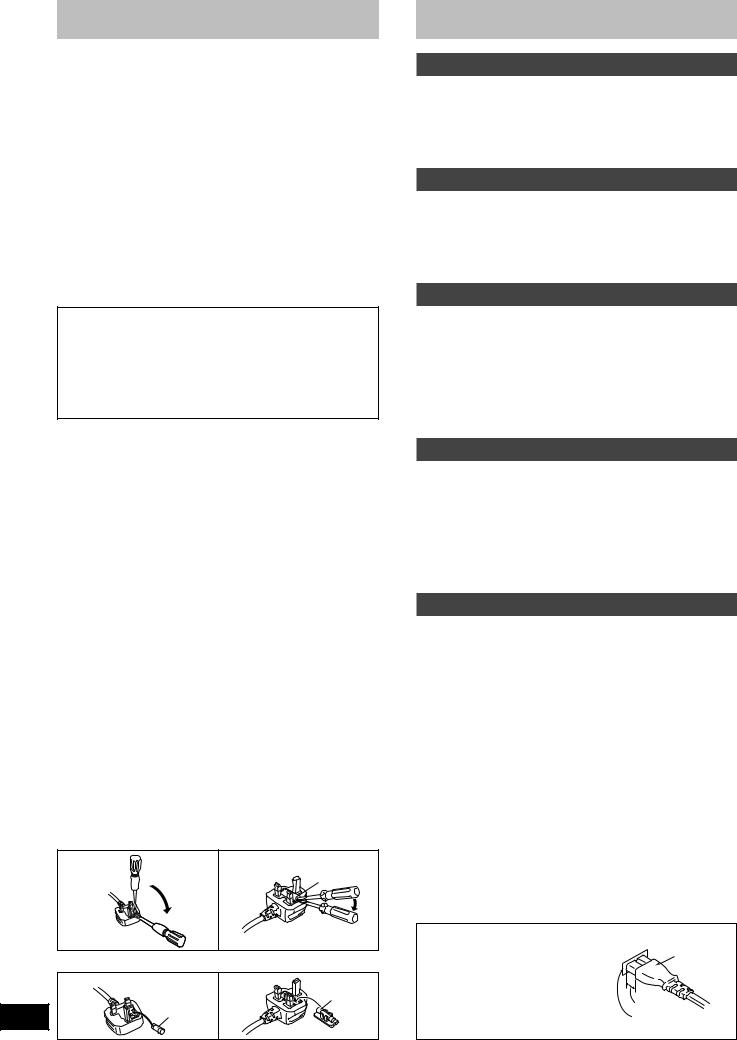
Caution for AC mains lead
(For the United Kingdom)
(“EB” area code model only)
For your safety, please read the following text carefully.
This appliance is supplied with a moulded three pin mains plug for your safety and convenience.
A 5-ampere fuse is fitted in this plug.
Should the fuse need to be replaced please ensure that the replacement fuse has a rating of 5-ampere and that it is approved by
ASTA or BSI to BS1362.
Check for the ASTA mark mor the BSI mark oon the body of the fuse.
If the plug contains a removable fuse cover you must ensure that it is refitted when the fuse is replaced.
If you lose the fuse cover the plug must not be used until a replacement cover is obtained.
A replacement fuse cover can be purchased from your local dealer.
CAUTION!
IF THE FITTED MOULDED PLUG IS UNSUITABLE FOR THE
SOCKET OUTLET IN YOUR HOME THEN THE FUSE SHOULD BE REMOVED AND THE PLUG CUT OFF AND
DISPOSED OF SAFELY.
THERE IS A DANGER OF SEVERE ELECTRICAL SHOCK IF
THE CUT OFF PLUG IS INSERTED INTO ANY 13-AMPERE SOCKET.
If a new plug is to be fitted please observe the wiring code as stated below.
If in any doubt please consult a qualified electrician.
IMPORTANT
The wires in this mains lead are coloured in accordance with the following code:
Blue: Neutral, Brown: Live.
As these colours may not correspond with the coloured markings identifying the terminals in your plug, proceed as follows:
The wire which is coloured Blue must be connected to the terminal which is marked with the letter N or coloured Black or Blue.
The wire which is coloured Brown must be connected to the terminal which is marked with the letter L or coloured Brown or Red.
WARNING: DO NOT CONNECT EITHER WIRE TO THE EARTH TERMINAL WHICH IS MARKED WITH THE LETTER E, BY THE EARTH SYMBOL n OR COLOURED GREEN OR GREEN/YELLOW.
THIS PLUG IS NOT WATERPROOF—KEEP DRY.
Before use
Remove the connector cover.
How to replace the fuse
The location of the fuse differ according to the type of AC mains plug (figures A and B). Confirm the AC mains plug fitted and follow the instructions below.
Illustrations may differ from actual AC mains plug.
1. Open the fuse cover with a screwdriver.
Figure A |
Figure B |
|
Fuse cover |
2. Replace the fuse and close or attach the fuse cover.
Figure A |
Figure B |
|
Fuse |
2 |
(5 ampere) |
Fuse |
|
RQT6901 |
(5 ampere) |
|
Safety precautions
Placement
Set the unit up on an even surface away from direct sunlight, high temperatures, high humidity, and excessive vibration. These conditions can damage the cabinet and other components, thereby shortening the unit’s service life.
Voltage
Do not use high voltage power sources. This can overload the unit and cause a fire.
Do not use a DC power source. Check the source carefully when setting the unit up on a ship or other place where DC is used.
AC mains lead protection
Ensure the AC mains lead is connected correctly and not damaged. Poor connection and lead damage can cause fire or electric shock. Do not pull, bend, or place heavy items on the lead.
Grasp the plug firmly when unplugging the lead. Pulling the AC mains lead can cause electric shock.
Do not handle the plug with wet hands. This can cause electric shock.
Foreign matter
Do not let metal objects fall inside the unit. This can cause electric shock or malfunction.
Do not let liquids get into the unit. This can cause electric shock or malfunction. If this occurs, immediately disconnect the unit from the power supply and contact your dealer.
Do not spray insecticides onto or into the unit. They contain flammable gases which can ignite if sprayed into the unit.
Service
Do not attempt to repair this unit by yourself. If sound is interrupted, indicators fail to light, smoke appears, or any other problem that is not covered in these operating instructions occurs, disconnect the AC mains lead and contact your dealer or an authorized service center.
Electric shock or damage to the unit can occur if the unit is repaired, disassembled or reconstructed by unqualified persons.
Extend operating life by disconnecting the unit from the power source if it is not to be used for a long time.
Insertion of connector |
|
|
Even when the connector is per- |
Connector |
|
fectly inserted, depending on the |
|
|
type of inlet used, the front part of |
|
|
the connector may jut out as shown |
|
|
in the drawing. |
Approx. 6 mm |
|
However there is no problem using |
||
Appliance inlet |
||
the unit. |
|
 Loading...